EP3179050A1 - Steam turbine rotor seal radial key member, related assembly and steam turbine - Google Patents
Steam turbine rotor seal radial key member, related assembly and steam turbine Download PDFInfo
- Publication number
- EP3179050A1 EP3179050A1 EP16201569.7A EP16201569A EP3179050A1 EP 3179050 A1 EP3179050 A1 EP 3179050A1 EP 16201569 A EP16201569 A EP 16201569A EP 3179050 A1 EP3179050 A1 EP 3179050A1
- Authority
- EP
- European Patent Office
- Prior art keywords
- rotor
- key member
- circumferential seal
- steam turbine
- slot
- Prior art date
- Legal status (The legal status is an assumption and is not a legal conclusion. Google has not performed a legal analysis and makes no representation as to the accuracy of the status listed.)
- Granted
Links
- 230000000295 complement effect Effects 0.000 claims abstract description 17
- 239000000463 material Substances 0.000 claims description 11
- 229910000831 Steel Inorganic materials 0.000 claims description 3
- 239000010959 steel Substances 0.000 claims description 3
- 239000012530 fluid Substances 0.000 description 3
- 238000013459 approach Methods 0.000 description 2
- 230000000712 assembly Effects 0.000 description 2
- 238000000429 assembly Methods 0.000 description 2
- NPURPEXKKDAKIH-UHFFFAOYSA-N iodoimino(oxo)methane Chemical compound IN=C=O NPURPEXKKDAKIH-UHFFFAOYSA-N 0.000 description 2
- VYZAMTAEIAYCRO-UHFFFAOYSA-N Chromium Chemical compound [Cr] VYZAMTAEIAYCRO-UHFFFAOYSA-N 0.000 description 1
- 238000010276 construction Methods 0.000 description 1
- 230000008878 coupling Effects 0.000 description 1
- 238000010168 coupling process Methods 0.000 description 1
- 238000005859 coupling reaction Methods 0.000 description 1
- 230000014759 maintenance of location Effects 0.000 description 1
- 238000000034 method Methods 0.000 description 1
- 230000000717 retained effect Effects 0.000 description 1
- 238000007789 sealing Methods 0.000 description 1
- 230000003068 static effect Effects 0.000 description 1
Images





Classifications
-
- F—MECHANICAL ENGINEERING; LIGHTING; HEATING; WEAPONS; BLASTING
- F01—MACHINES OR ENGINES IN GENERAL; ENGINE PLANTS IN GENERAL; STEAM ENGINES
- F01D—NON-POSITIVE DISPLACEMENT MACHINES OR ENGINES, e.g. STEAM TURBINES
- F01D11/00—Preventing or minimising internal leakage of working-fluid, e.g. between stages
- F01D11/005—Sealing means between non relatively rotating elements
-
- F—MECHANICAL ENGINEERING; LIGHTING; HEATING; WEAPONS; BLASTING
- F16—ENGINEERING ELEMENTS AND UNITS; GENERAL MEASURES FOR PRODUCING AND MAINTAINING EFFECTIVE FUNCTIONING OF MACHINES OR INSTALLATIONS; THERMAL INSULATION IN GENERAL
- F16J—PISTONS; CYLINDERS; SEALINGS
- F16J15/00—Sealings
- F16J15/16—Sealings between relatively-moving surfaces
- F16J15/32—Sealings between relatively-moving surfaces with elastic sealings, e.g. O-rings
- F16J15/3268—Mounting of sealing rings
-
- F—MECHANICAL ENGINEERING; LIGHTING; HEATING; WEAPONS; BLASTING
- F01—MACHINES OR ENGINES IN GENERAL; ENGINE PLANTS IN GENERAL; STEAM ENGINES
- F01D—NON-POSITIVE DISPLACEMENT MACHINES OR ENGINES, e.g. STEAM TURBINES
- F01D11/00—Preventing or minimising internal leakage of working-fluid, e.g. between stages
- F01D11/001—Preventing or minimising internal leakage of working-fluid, e.g. between stages for sealing space between stator blade and rotor
-
- F—MECHANICAL ENGINEERING; LIGHTING; HEATING; WEAPONS; BLASTING
- F01—MACHINES OR ENGINES IN GENERAL; ENGINE PLANTS IN GENERAL; STEAM ENGINES
- F01D—NON-POSITIVE DISPLACEMENT MACHINES OR ENGINES, e.g. STEAM TURBINES
- F01D5/00—Blades; Blade-carrying members; Heating, heat-insulating, cooling or antivibration means on the blades or the members
- F01D5/02—Blade-carrying members, e.g. rotors
-
- F—MECHANICAL ENGINEERING; LIGHTING; HEATING; WEAPONS; BLASTING
- F16—ENGINEERING ELEMENTS AND UNITS; GENERAL MEASURES FOR PRODUCING AND MAINTAINING EFFECTIVE FUNCTIONING OF MACHINES OR INSTALLATIONS; THERMAL INSULATION IN GENERAL
- F16J—PISTONS; CYLINDERS; SEALINGS
- F16J15/00—Sealings
- F16J15/44—Free-space packings
- F16J15/447—Labyrinth packings
- F16J15/4472—Labyrinth packings with axial path
-
- F—MECHANICAL ENGINEERING; LIGHTING; HEATING; WEAPONS; BLASTING
- F01—MACHINES OR ENGINES IN GENERAL; ENGINE PLANTS IN GENERAL; STEAM ENGINES
- F01D—NON-POSITIVE DISPLACEMENT MACHINES OR ENGINES, e.g. STEAM TURBINES
- F01D5/00—Blades; Blade-carrying members; Heating, heat-insulating, cooling or antivibration means on the blades or the members
- F01D5/30—Fixing blades to rotors; Blade roots ; Blade spacers
- F01D5/3023—Fixing blades to rotors; Blade roots ; Blade spacers of radial insertion type, e.g. in individual recesses
- F01D5/303—Fixing blades to rotors; Blade roots ; Blade spacers of radial insertion type, e.g. in individual recesses in a circumferential slot
- F01D5/3038—Fixing blades to rotors; Blade roots ; Blade spacers of radial insertion type, e.g. in individual recesses in a circumferential slot the slot having inwardly directed abutment faces on both sides
-
- F—MECHANICAL ENGINEERING; LIGHTING; HEATING; WEAPONS; BLASTING
- F05—INDEXING SCHEMES RELATING TO ENGINES OR PUMPS IN VARIOUS SUBCLASSES OF CLASSES F01-F04
- F05D—INDEXING SCHEME FOR ASPECTS RELATING TO NON-POSITIVE-DISPLACEMENT MACHINES OR ENGINES, GAS-TURBINES OR JET-PROPULSION PLANTS
- F05D2220/00—Application
- F05D2220/30—Application in turbines
- F05D2220/31—Application in turbines in steam turbines
-
- F—MECHANICAL ENGINEERING; LIGHTING; HEATING; WEAPONS; BLASTING
- F05—INDEXING SCHEMES RELATING TO ENGINES OR PUMPS IN VARIOUS SUBCLASSES OF CLASSES F01-F04
- F05D—INDEXING SCHEME FOR ASPECTS RELATING TO NON-POSITIVE-DISPLACEMENT MACHINES OR ENGINES, GAS-TURBINES OR JET-PROPULSION PLANTS
- F05D2260/00—Function
- F05D2260/30—Retaining components in desired mutual position
- F05D2260/36—Retaining components in desired mutual position by a form fit connection, e.g. by interlocking
Definitions
- the subject matter disclosed herein relates to steam turbines. Specifically, the subject matter disclosed herein relates to seal devices in steam turbines.
- Steam turbines include static nozzle assemblies that direct flow of a working fluid into turbine buckets connected to a rotating rotor.
- the nozzle construction (including a plurality of nozzles, or “airfoils") is sometimes referred to as a "diaphragm" or “nozzle assembly stage.”
- Steam turbine diaphragms include two halves, which are assembled around the rotor, creating horizontal joints between these two halves. Each turbine diaphragm stage is vertically supported by support bars, support lugs or support screws on each side of the diaphragm at the respective horizontal joints.
- the horizontal joints of the diaphragm also correspond to horizontal joints of the turbine casing, which surrounds the steam turbine diaphragm.
- Steam turbines utilize seals between rotor components and stator components, typically radially outward of the rotor bucket tip and radially inward of the diaphragm nozzle cover (stator). While some seals are formed as teeth on the rotor and/or stator, other configurations include a circumferential (or, rotating) seal that is located within a circumferential dovetail slot in the rotor. These rotating (circumferential) seals present unique design constraints, including, radial retention, rotation control, circumferential locking, and consistency of sealing across the circumference.
- Various embodiments include a rotor key member, along with a related assembly and steam turbine.
- Particular embodiments include a rotor key member for radially retaining a circumferential seal in a steam turbine rotor body, the rotor key member including: a main body sized to contact an axial face of the circumferential seal; and a hook extending from the main body in a direction axially away from the circumferential seal, the hook sized to substantially complement a corresponding shelf in the steam turbine rotor body to restrict movement of the circumferential seal relative to the steam turbine rotor body.
- a first aspect of the disclosure includes a rotor key member for radially retaining a circumferential seal in a steam turbine rotor body, the rotor key member including: a main body sized to contact an axial face of the circumferential seal; and a hook extending from the main body in a direction axially away from the circumferential seal, the hook sized to substantially complement a corresponding shelf in the steam turbine rotor body to restrict movement of the circumferential seal relative to the steam turbine rotor body.
- a second aspect of the disclosure includes a steam turbine rotor assembly having: a rotor body having a slot extending substantially entirely circumferentially about a primary axis of the rotor body, the slot including: a primary slot extending substantially an entire circumferential distance about the rotor body; and a secondary slot extending axially from the primary slot and spanning only a portion of the circumferential distance about the rotor body; a circumferential seal within the primary slot spanning substantially the entire circumferential distance about the rotor body; a set of seal retaining members within the primary slot contacting an axial face of the circumferential seal; and a first rotor key member having: a main body sized to contact an axial face of the circumferential seal; and a hook extending from the main body in a direction axially away from the circumferential seal, the hook sized to substantially complement a corresponding shelf in the primary slot.
- a third aspect of the disclosure includes a steam turbine having: a casing; and a rotor assembly at least partially contained within the casing, the rotor assembly having: a rotor body having a slot extending substantially entirely circumferentially about a primary axis of the rotor body, the slot including: a primary slot extending substantially an entire circumferential distance about the rotor body; and a secondary slot extending axially from the primary slot and spanning only a portion of the circumferential distance about the rotor body; a circumferential seal within the primary slot spanning substantially the entire circumferential distance about the rotor body; a set of seal retaining members within the primary slot contacting an axial face of the circumferential seal; and a first rotor key member having: a main body sized to contact an axial face of the circumferential seal; and a hook extending from the main body in a direction axially away from the circumferential seal, the hook sized to substantially complement a corresponding shelf in the primary slot.
- the subject matter disclosed herein relates to steam turbines. Specifically, the subject matter disclosed herein relates to rotating seals in steam turbines.
- a device e.g., key member
- a circumferential (rotatable) seal in a steam turbine, both radially retaining the seal as well as preventing rotation.
- Conventional approaches to retain circumferential seals allow for unwanted rotation, and are also susceptible to slipping and creep, which can both diminish the effectiveness of the seal and wear on the seal and adjacent components.
- various embodiments include a radial key member sized to engage a key slot within the rotor body and radially retain an adjacent circumferential seal. In some cases, the radial key member is located between circumferentially disposed seal retaining members.
- a second key member is used to lock the radial key member in place and retain the rotating seal in the circumferential dimension.
- the radial key member can include at least one axially extending hook sized to engage the slot in the rotor body.
- the radial key member has a sufficient axial width to contact both the circumferential seal and the axially facing wall of the key slot in the rotor body.
- the "A" axis represents axial orientation (along the axis of the turbine rotor, sometimes referred to as the turbine centerline, omitted for clarity).
- the terms “axial” and/or “axially” refer to the relative position/direction of objects along axis A, which is substantially parallel with the axis of rotation of the turbomachine (in particular, the rotor section).
- the terms “radial” and/or “radially” refer to the relative position/direction of objects along axis (r), which is substantially perpendicular with axis A and intersects axis A at only one location.
- circumferential and/or circumferentially refer to the relative position/direction of objects along a circumference (c) which surrounds axis A but does not intersect the axis A at any location.
- Identically labeled elements in the Figures depict substantially similar (e.g., identical) components.
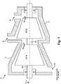
- FIG. 1 a partial cross-sectional schematic view of steam turbine 2 (e.g., a high-pressure / intermediate-pressure steam turbine) is shown.
- Steam turbine 2 may include, for example, a low pressure (LP) section 4 and a high pressure (HP) section 6 (it is understood that either LP section 4 or HP section 6 can include an intermediate pressure (IP) section, as is known in the art).
- the LP section 4 and HP section 6 are at least partially encased in casing 7. Steam may enter the HP section 6 and LP section 4 via one or more inlets 8 in casing 7, and flow axially downstream from the inlet(s) 8.
- HP section 6 and LP section 4 are joined by a common shaft 10, which may contact bearings 12, allowing for rotation of the shaft 10, as working fluid (steam) forces rotation of the blades within each of LP section 4 and HP section 6.
- working fluid e.g., steam
- the center line (CL) 16 of HP section 6 and LP section 4 is shown as a reference point.
- Both LP section 4 and HP section 6 can include diaphragm assemblies, which are contained within segments of casing 7.
- FIG. 2 shows a schematic three-dimensional perspective view of a rotor key member 20 within a steam turbine rotor assembly (or simply, rotor assembly) 22 according to various embodiments.
- FIG. 3 which is referred to simultaneously with FIG. 2 , shows a schematic cut-away view of the rotor assembly 22 according to various embodiments.
- rotor key member 20 is sized (configured) to retain a circumferential seal 24 in a steam turbine (e.g., in a rotor assembly 22 within a steam turbine, such as steam turbine 2).
- Rotor assembly 22 can be a component within an HP, IP and/or LP section of a steam turbine (e.g., HP 6, LP 4, etc. section of steam turbine 2).
- Rotor key member 20 can include: a main body 26 sized to contact an axial face 56 (axially facing surface) of the circumferential seal 24, and a hook 28 extending from main body 26 in a direction axially away from circumferential seal 24.
- Hook 28 is sized to substantially (e.g., completely or nearly completely) complement a corresponding shelf 30 in rotor body 46 to restrict movement of circumferential seal 24 relative to the rotor body 46 (e.g., to restrict axial and/or radial movement of circumferential seal 24).
- Hook 28 in some cases extends (e.g., in some cases, substantially perpendicularly (e.g., perpendicular within an acceptable margin of deviation, such as 1-3% deviation) from main body 26.
- hook 28 has a first surface 32 sized to contact shelf 30 in rotor body 46, where first surface 32 is rounded or otherwise bulbous to match a correspondingly rounded or otherwise bulbous characteristic of shelf 30, and a second surface 34 (distinct from first surface 32) substantially opposing first surface 32 and located axially inward of first surface 32.
- second surface 34 can include a fillet, bevel or chamfer edge 36 extending between main body 26 and hook 28 at second surface 34.
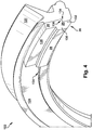
- FIG. 4 shows a three-dimensional perspective view of an alternative embodiment of a portion of a rotor assembly 122, including a rotor key member 120 and a circumferential seal (segment) 124.
- FIG. 5 which is referred to simultaneously with FIG. 4 , shows a schematic cut-away view of the rotor assembly 122 according to various embodiments.
- rotor key member 120 can have several features in common with rotor key member 20, while circumferential seal 124 can have several features in common with circumferential seal 24.
- hook 28 of rotor key member 120 can include a first portion 130 extending from main body 26 in a direction axially away from circumferential seal 124, and a second portion 132 extending radially inward from first portion 130.
- circumferential seal 124 can include a shelf 134, and the main body 26 and second portion 132 of hook 28 can form a ledge 136 sized to complement (e.g., fit flush with, or nearly flush with) shelf 134 in circumferential seal 124.
- shelf 134 in circumferential seal 124 can extend a portion of a circumferential distance about rotor body 46, e.g., a sufficient distance to engage ledge 136.
- rotor key member 120 is sized to slide circumferentially into rotor body 46 and engage shelf 30.
- both main body 26 and hook 28 in rotor key members 20, 120 can be substantially unitary and formed of a common material.
- This material could include a steel, for example, including approximately 2.5 percent to approximately 12 percent chrome (e.g., INCO 615 or INCO 718).
- rotor key members 20, 120 can be made of a single piece of material, e.g., forged, cast, molded or otherwise formed from a common material.
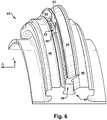
- FIG. 6 shows a schematic three-dimensional perspective view of the rotor assembly 22 of FIG. 3 , excluding rotor key member 20.
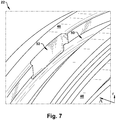
- FIG. 7 shows a three-dimensional perspective view of a portion of rotor assembly 22, excluding circumferential seal 24 and rotor key member 20.
- FIG. 8 shows a three-dimensional perspective view of a portion of rotor assembly 20, including rotor key member 20, as described herein.
- FIG. 9 shows the rotor assembly 22 of FIG. 8 , further including a second rotor key member 220.
- rotor assembly 22 is shown including a rotor body 46 having a slot 48 extending substantially entirely circumferentially about a primary axis (A) of the rotor body 46 (primary axis A corresponding with axis of rotation of steam turbine).
- Slot 48 can include a primary slot 50 extending substantially an entire circumferential distance about rotor body 46, and a secondary slot 52 ( FIGS. 6 , 7 , 8 ) extending axially from primary slot 50 and spanning only a portion of the circumferential distance about rotor body 46. As shown in FIG.
- rotor assembly 22 can further include circumferential seal 24 within primary slot 50, spanning substantially the entire circumferential distance about rotor body 46 (e.g., in sections or as one continuous piece of material).
- FIG. 9 illustrates an additional component in rotor assembly 22, including second rotor key member 220 in secondary slot 52, circumferentially retaining rotor key member 20 (or, rotor key member 120) within primary slot 50. Both second rotor key member 220 and rotor key member 20 (or, rotor key member 120) contact axial face 56 of circumferential seal 24. As shown in FIG. 9 , second rotor key member 220 is located within (and substantially fills) secondary slot 52, and contacts axial face 56 of circumferential seal 24.
- Rotor key member 220 may be sized to slide (radially) into or out of secondary slot 52 to lock rotor key member(s) 20, 120, e.g., using among other things, a hook, a weld, or other coupling mechanism. Rotor key member 220 can be inserted/removed from secondary slot 52 in order to lock/unlock rotor key member(s) 20, 120 (and in turn, circumferential seal 24). As shown in FIG. 6 and FIG. 8 , in some embodiments, circumferential seal 24 can include a recess 43 extending only partially circumferentially, marking a break between adjacent segments of axial face 56.
- this recess 43 can be sized to accommodate second rotor key member 220, and coincide with secondary slot 52.
- second rotor key member 220 is sized (configured) to retain the (first) rotor key member 20 (or rotor key member 120) in primary slot 50, where second rotor key member 220 is sized to substantially fill secondary slot 52 and restrict circumferential movement of the circumferential seal 24.
- rotor key member 20 and/or rotor key member 120, which may be interchanged in various embodiments described herein, can be w sized to pass radially through 52 secondary slot and circumferentially into primary slot 50 to engage shelf 30 in the primary slot 50 and contact the circumferential seal 24.
- rotor assembly 22 can retain circumferential seal 24 by placing axial pressure on axial face 56.
- seal retaining members 54 can place axial pressure on circumferential seal (at axial face 56), while rotor key member 20 locks seal retaining members 54 circumferentially in place (where first arm 28 is retained by secondary slot 52).
- rotor key member 20 engages the axial face of circumferential seal 24 within recess 43, restricting circumferential rotation of circumferential seal 24 relative to rotor body 46.
- hook 34 engages radially inner surface of circumferential seal 24, to restrict axial rotation of that circumferential seal 24 relative to rotor body 46.
- rotor key member 20 (and rotor assembly 22) can be utilized in a plurality of stages within a steam turbine (e.g., steam turbine 2), and can aid in both assembly/disassembly of circumferential seal components, as well as reduce wear and complications from component failure.
- a steam turbine e.g., steam turbine 2
Landscapes
- Engineering & Computer Science (AREA)
- General Engineering & Computer Science (AREA)
- Mechanical Engineering (AREA)
- Turbine Rotor Nozzle Sealing (AREA)
- Sealing Using Fluids, Sealing Without Contact, And Removal Of Oil (AREA)
- Gasket Seals (AREA)
Abstract
Description
- The subject matter disclosed herein relates to steam turbines. Specifically, the subject matter disclosed herein relates to seal devices in steam turbines.
- Steam turbines include static nozzle assemblies that direct flow of a working fluid into turbine buckets connected to a rotating rotor. The nozzle construction (including a plurality of nozzles, or "airfoils") is sometimes referred to as a "diaphragm" or "nozzle assembly stage." Steam turbine diaphragms include two halves, which are assembled around the rotor, creating horizontal joints between these two halves. Each turbine diaphragm stage is vertically supported by support bars, support lugs or support screws on each side of the diaphragm at the respective horizontal joints. The horizontal joints of the diaphragm also correspond to horizontal joints of the turbine casing, which surrounds the steam turbine diaphragm.
- Steam turbines utilize seals between rotor components and stator components, typically radially outward of the rotor bucket tip and radially inward of the diaphragm nozzle cover (stator). While some seals are formed as teeth on the rotor and/or stator, other configurations include a circumferential (or, rotating) seal that is located within a circumferential dovetail slot in the rotor. These rotating (circumferential) seals present unique design constraints, including, radial retention, rotation control, circumferential locking, and consistency of sealing across the circumference.
- Various embodiments include a rotor key member, along with a related assembly and steam turbine. Particular embodiments include a rotor key member for radially retaining a circumferential seal in a steam turbine rotor body, the rotor key member including: a main body sized to contact an axial face of the circumferential seal; and a hook extending from the main body in a direction axially away from the circumferential seal, the hook sized to substantially complement a corresponding shelf in the steam turbine rotor body to restrict movement of the circumferential seal relative to the steam turbine rotor body.
- A first aspect of the disclosure includes a rotor key member for radially retaining a circumferential seal in a steam turbine rotor body, the rotor key member including: a main body sized to contact an axial face of the circumferential seal; and a hook extending from the main body in a direction axially away from the circumferential seal, the hook sized to substantially complement a corresponding shelf in the steam turbine rotor body to restrict movement of the circumferential seal relative to the steam turbine rotor body.
- A second aspect of the disclosure includes a steam turbine rotor assembly having: a rotor body having a slot extending substantially entirely circumferentially about a primary axis of the rotor body, the slot including: a primary slot extending substantially an entire circumferential distance about the rotor body; and a secondary slot extending axially from the primary slot and spanning only a portion of the circumferential distance about the rotor body; a circumferential seal within the primary slot spanning substantially the entire circumferential distance about the rotor body; a set of seal retaining members within the primary slot contacting an axial face of the circumferential seal; and a first rotor key member having: a main body sized to contact an axial face of the circumferential seal; and a hook extending from the main body in a direction axially away from the circumferential seal, the hook sized to substantially complement a corresponding shelf in the primary slot.
- A third aspect of the disclosure includes a steam turbine having: a casing; and a rotor assembly at least partially contained within the casing, the rotor assembly having: a rotor body having a slot extending substantially entirely circumferentially about a primary axis of the rotor body, the slot including: a primary slot extending substantially an entire circumferential distance about the rotor body; and a secondary slot extending axially from the primary slot and spanning only a portion of the circumferential distance about the rotor body; a circumferential seal within the primary slot spanning substantially the entire circumferential distance about the rotor body; a set of seal retaining members within the primary slot contacting an axial face of the circumferential seal; and a first rotor key member having: a main body sized to contact an axial face of the circumferential seal; and a hook extending from the main body in a direction axially away from the circumferential seal, the hook sized to substantially complement a corresponding shelf in the primary slot.
- These and other features of this invention will be more readily understood from the following detailed description of the various aspects of the invention taken in conjunction with the accompanying drawings that depict various embodiments of the disclosure, in which:
-
FIG. 1 shows a partial cross-sectional schematic view of steam turbine according to various embodiments. -
FIG. 2 shows a schematic three-dimensional perspective view of a steam turbine rotor assembly according to various embodiments of the disclosure. -
FIG. 3 shows a schematic cut-away view of a steam turbine rotor assembly according to various embodiments of the disclosure. -
FIG. 4 shows a schematic three-dimensional perspective view of a portion of a steam turbine rotor assembly according to various embodiments of the disclosure. -
FIG. 5 shows a schematic cut-away view of a steam turbine rotor assembly according to various embodiments of the disclosure. -
FIG. 6 shows a schematic three-dimensional perspective view of a portion of a steam turbine rotor assembly according to various embodiments of the disclosure. -
FIG. 7 shows a three-dimensional perspective view of a portion of the rotor assembly ofFIG. 6 , excluding the circumferential seal member, according to various embodiments of the disclosure. -
FIG. 8 shows a three-dimensional perspective view of a portion of a rotor assembly according to various embodiments of the disclosure. -
FIG. 9 shows a three-dimensional perspective view of a rotor assembly according to various embodiments of the disclosure. - It is noted that the drawings of the invention are not necessarily to scale. The drawings are intended to depict only typical aspects of the invention, and therefore should not be considered as limiting the scope of the invention. In the drawings, like numbering represents like elements between the drawings.
- The subject matter disclosed herein relates to steam turbines. Specifically, the subject matter disclosed herein relates to rotating seals in steam turbines.
- According to various embodiments of the disclosure, a device (e.g., key member) is configured to lock/unlock a circumferential (rotatable) seal in a steam turbine, both radially retaining the seal as well as preventing rotation. Conventional approaches to retain circumferential seals allow for unwanted rotation, and are also susceptible to slipping and creep, which can both diminish the effectiveness of the seal and wear on the seal and adjacent components. In contrast to these conventional approaches, various embodiments include a radial key member sized to engage a key slot within the rotor body and radially retain an adjacent circumferential seal. In some cases, the radial key member is located between circumferentially disposed seal retaining members. In additional embodiments, a second key member is used to lock the radial key member in place and retain the rotating seal in the circumferential dimension. The radial key member can include at least one axially extending hook sized to engage the slot in the rotor body. The radial key member has a sufficient axial width to contact both the circumferential seal and the axially facing wall of the key slot in the rotor body.
- As denoted in these Figures, the "A" axis represents axial orientation (along the axis of the turbine rotor, sometimes referred to as the turbine centerline, omitted for clarity). As used herein, the terms "axial" and/or "axially" refer to the relative position/direction of objects along axis A, which is substantially parallel with the axis of rotation of the turbomachine (in particular, the rotor section). As further used herein, the terms "radial" and/or "radially" refer to the relative position/direction of objects along axis (r), which is substantially perpendicular with axis A and intersects axis A at only one location. Additionally, the terms "circumferential" and/or "circumferentially" refer to the relative position/direction of objects along a circumference (c) which surrounds axis A but does not intersect the axis A at any location. Identically labeled elements in the Figures depict substantially similar (e.g., identical) components.
- Turning to
FIG. 1 , a partial cross-sectional schematic view of steam turbine 2 (e.g., a high-pressure / intermediate-pressure steam turbine) is shown.Steam turbine 2 may include, for example, a low pressure (LP)section 4 and a high pressure (HP) section 6 (it is understood that eitherLP section 4 orHP section 6 can include an intermediate pressure (IP) section, as is known in the art). TheLP section 4 and HPsection 6 are at least partially encased incasing 7. Steam may enter the HPsection 6 andLP section 4 via one ormore inlets 8 incasing 7, and flow axially downstream from the inlet(s) 8. In some embodiments, HPsection 6 andLP section 4 are joined by acommon shaft 10, which may contactbearings 12, allowing for rotation of theshaft 10, as working fluid (steam) forces rotation of the blades within each ofLP section 4 andHP section 6. After performing mechanical work on the blades withinLP section 4 andHP section 6, working fluid (e.g., steam) may exit throughoutlet 14 incasing 7. The center line (CL) 16 ofHP section 6 andLP section 4 is shown as a reference point. BothLP section 4 andHP section 6 can include diaphragm assemblies, which are contained within segments ofcasing 7. -
FIG. 2 shows a schematic three-dimensional perspective view of arotor key member 20 within a steam turbine rotor assembly (or simply, rotor assembly) 22 according to various embodiments.FIG. 3 , which is referred to simultaneously withFIG. 2 , shows a schematic cut-away view of therotor assembly 22 according to various embodiments. As shown inFIG. 2 andFIG. 3 ,rotor key member 20 is sized (configured) to retain acircumferential seal 24 in a steam turbine (e.g., in arotor assembly 22 within a steam turbine, such as steam turbine 2). It is understood that the rotor assembly 22 (including circumferential seal 24) can be a component within an HP, IP and/or LP section of a steam turbine (e.g., HP 6,LP 4, etc. section of steam turbine 2).Rotor key member 20 can include: amain body 26 sized to contact an axial face 56 (axially facing surface) of thecircumferential seal 24, and ahook 28 extending frommain body 26 in a direction axially away fromcircumferential seal 24.Hook 28 is sized to substantially (e.g., completely or nearly completely) complement acorresponding shelf 30 inrotor body 46 to restrict movement ofcircumferential seal 24 relative to the rotor body 46 (e.g., to restrict axial and/or radial movement of circumferential seal 24). Hook 28 in some cases extends (e.g., in some cases, substantially perpendicularly (e.g., perpendicular within an acceptable margin of deviation, such as 1-3% deviation) frommain body 26. In various embodiments,hook 28 has afirst surface 32 sized to contactshelf 30 inrotor body 46, wherefirst surface 32 is rounded or otherwise bulbous to match a correspondingly rounded or otherwise bulbous characteristic ofshelf 30, and a second surface 34 (distinct from first surface 32) substantially opposingfirst surface 32 and located axially inward offirst surface 32. In some cases, as shown in the embodiments inFIG. 3 ,second surface 34 can include a fillet, bevel orchamfer edge 36 extending betweenmain body 26 and hook 28 atsecond surface 34. -
FIG. 4 shows a three-dimensional perspective view of an alternative embodiment of a portion of arotor assembly 122, including arotor key member 120 and a circumferential seal (segment) 124.FIG. 5 , which is referred to simultaneously withFIG. 4 , shows a schematic cut-away view of therotor assembly 122 according to various embodiments. As shown inFIG. 4 andFIG. 5 , rotorkey member 120 can have several features in common with rotorkey member 20, whilecircumferential seal 124 can have several features in common withcircumferential seal 24. In some embodiments, hook 28 of rotorkey member 120 can include afirst portion 130 extending frommain body 26 in a direction axially away fromcircumferential seal 124, and asecond portion 132 extending radially inward fromfirst portion 130. In some cases,circumferential seal 124 can include ashelf 134, and themain body 26 andsecond portion 132 ofhook 28 can form aledge 136 sized to complement (e.g., fit flush with, or nearly flush with)shelf 134 incircumferential seal 124. In some cases, as shown inFIG. 4 ,shelf 134 incircumferential seal 124 can extend a portion of a circumferential distance aboutrotor body 46, e.g., a sufficient distance to engageledge 136. In various embodiments, rotorkey member 120 is sized to slide circumferentially intorotor body 46 and engageshelf 30. - In various embodiments, both
main body 26 and hook 28 (in rotorkey members 20, 120) can be substantially unitary and formed of a common material. This material could include a steel, for example, including approximately 2.5 percent to approximately 12 percent chrome (e.g., INCO 615 or INCO 718). In some cases, rotorkey members -
FIG. 6 shows a schematic three-dimensional perspective view of therotor assembly 22 ofFIG. 3 , excluding rotorkey member 20.FIG. 7 shows a three-dimensional perspective view of a portion ofrotor assembly 22, excludingcircumferential seal 24 and rotorkey member 20.FIG. 8 shows a three-dimensional perspective view of a portion ofrotor assembly 20, including rotorkey member 20, as described herein.FIG. 9 shows therotor assembly 22 ofFIG. 8 , further including a second rotorkey member 220. - Returning to
FIG. 3 , but with continuing reference toFIGS. 6-9 ,rotor assembly 22 is shown including arotor body 46 having aslot 48 extending substantially entirely circumferentially about a primary axis (A) of the rotor body 46 (primary axis A corresponding with axis of rotation of steam turbine).Slot 48 can include aprimary slot 50 extending substantially an entire circumferential distance aboutrotor body 46, and a secondary slot 52 (FIGS. 6 ,7 ,8 ) extending axially fromprimary slot 50 and spanning only a portion of the circumferential distance aboutrotor body 46. As shown inFIG. 3 ,rotor assembly 22 can further includecircumferential seal 24 withinprimary slot 50, spanning substantially the entire circumferential distance about rotor body 46 (e.g., in sections or as one continuous piece of material).FIG. 9 illustrates an additional component inrotor assembly 22, including second rotorkey member 220 insecondary slot 52, circumferentially retaining rotor key member 20 (or, rotor key member 120) withinprimary slot 50. Both second rotorkey member 220 and rotor key member 20 (or, rotor key member 120) contactaxial face 56 ofcircumferential seal 24. As shown inFIG. 9 , second rotorkey member 220 is located within (and substantially fills)secondary slot 52, and contactsaxial face 56 ofcircumferential seal 24. Rotorkey member 220 may be sized to slide (radially) into or out ofsecondary slot 52 to lock rotor key member(s) 20, 120, e.g., using among other things, a hook, a weld, or other coupling mechanism. Rotorkey member 220 can be inserted/removed fromsecondary slot 52 in order to lock/unlock rotor key member(s) 20, 120 (and in turn, circumferential seal 24). As shown inFIG. 6 andFIG. 8 , in some embodiments,circumferential seal 24 can include arecess 43 extending only partially circumferentially, marking a break between adjacent segments ofaxial face 56. In some cases, thisrecess 43 can be sized to accommodate second rotorkey member 220, and coincide withsecondary slot 52. As noted herein, second rotorkey member 220 is sized (configured) to retain the (first) rotor key member 20 (or rotor key member 120) inprimary slot 50, where second rotorkey member 220 is sized to substantially fillsecondary slot 52 and restrict circumferential movement of thecircumferential seal 24. In various embodiments, rotor key member 20 (and/or rotorkey member 120, which may be interchanged in various embodiments described herein), can be w sized to pass radially through 52 secondary slot and circumferentially intoprimary slot 50 to engageshelf 30 in theprimary slot 50 and contact thecircumferential seal 24. - During operation of
steam turbine 2,rotor assembly 22 can retaincircumferential seal 24 by placing axial pressure onaxial face 56. In particular, seal retaining members 54 can place axial pressure on circumferential seal (at axial face 56), while rotorkey member 20 locks seal retaining members 54 circumferentially in place (wherefirst arm 28 is retained by secondary slot 52). Additionally, rotorkey member 20 engages the axial face ofcircumferential seal 24 withinrecess 43, restricting circumferential rotation ofcircumferential seal 24 relative torotor body 46. Even further,hook 34 engages radially inner surface ofcircumferential seal 24, to restrict axial rotation of thatcircumferential seal 24 relative torotor body 46. It is understood that according to various embodiments, rotor key member 20 (and rotor assembly 22) can be utilized in a plurality of stages within a steam turbine (e.g., steam turbine 2), and can aid in both assembly/disassembly of circumferential seal components, as well as reduce wear and complications from component failure. - The terminology used herein is for the purpose of describing particular embodiments only and is not intended to be limiting of the disclosure. As used herein, the singular forms "a", "an" and "the" are intended to include the plural forms as well, unless the context clearly indicates otherwise. It will be further understood that the terms "comprises" and/or "comprising," when used in this specification, specify the presence of stated features, integers, steps, operations, elements, and/or components, but do not preclude the presence or addition of one or more other features, integers, steps, operations, elements, components, and/or groups thereof.
- This written description uses examples to disclose the invention, including the best mode, and also to enable any person skilled in the art to practice the invention, including making and using any devices or systems and performing any incorporated methods. The patentable scope of the invention is defined by the claims, and may include other examples that occur to those skilled in the art. Such other examples are intended to be within the scope of the claims if they have structural elements that do not differ from the literal language of the claims, or if they include equivalent structural elements with insubstantial differences from the literal languages of the claims. Various aspects and embodiments of the present invention will now be defined by the following numbered clauses:
- 1. A rotor key member for radially retaining a circumferential seal in a steam turbine rotor body, the rotor key member comprising:
- a main body sized to contact an axial face of the circumferential seal; and
- a hook extending from the main body in a direction axially away from the circumferential seal, the hook sized to substantially complement a corresponding shelf in the steam turbine rotor body to restrict movement of the circumferential seal relative to the steam turbine rotor body.
- 2. The rotor key member of clause 1, wherein the hook includes a first portion extending from the main body in the direction axially away from the circumferential seal, and a second portion extending radially inward from the first portion.
- 3. The rotor key member of
clause 2, wherein the main body and the second portion form a ledge sized to complement a corresponding shelf in the circumferential seal. - 4. The rotor key member of clause 1, wherein the main body and the hook are substantially unitary and formed of a common material.
- 5. The rotor key member of
clause 4, wherein the common material includes steel. - 6. The rotor key member of clause 1, wherein the hook has a first surface sized to contact the shelf in the steam turbine rotor body, the rotor key member further comprising a fillet, bevel or chamfer edge extending between the main body and the hook at a second surface of the hook distinct from the first surface.
- 7. A steam turbine rotor assembly comprising:
- a rotor body having a slot extending substantially entirely circumferentially about a primary axis of the rotor body, the slot including:
- a primary slot extending substantially an entire circumferential distance about the rotor body; and
- a secondary slot extending axially from the primary slot and spanning only a portion of the circumferential distance about the rotor body;
- a circumferential seal within the primary slot spanning substantially the entire circumferential distance about the rotor body;
- a set of seal retaining members within the primary slot contacting an axial face of the circumferential seal; and
- a first rotor key member having:
- a main body sized to contact an axial face of the circumferential seal; and
- a hook extending from the main body in a direction axially away from the circumferential seal, the hook sized to substantially complement a corresponding shelf in the primary slot.
- a rotor body having a slot extending substantially entirely circumferentially about a primary axis of the rotor body, the slot including:
- 8. The steam turbine rotor assembly of
clause 7, wherein the first rotor key member is sized to pass radially through the secondary slot and circumferentially into the primary slot to engage the shelf in the primary slot and contact the circumferential seal. - 9. The steam turbine rotor assembly of
clause 7, further comprising a second rotor key member for retaining the first rotor key member in the primary slot, the second rotor key member sized to substantially fill the secondary slot and restrict circumferential movement of the circumferential seal. - 10. The steam turbine rotor assembly of
clause 7, wherein the hook includes a first portion extending from the main body in the direction axially away from the circumferential seal, and a second portion extending radially inward from the first portion. - 11. The steam turbine rotor assembly of
clause 10, wherein the main body and the second portion form a ledge sized to complement a corresponding shelf in the circumferential seal. - 12. The steam turbine rotor assembly of
clause 7, wherein the main body and the hook are substantially unitary and formed of a common material. - 13. The steam turbine rotor assembly of
clause 7, wherein the hook has a first surface sized to contact the shelf in the rotor body, the rotor key member further comprising a fillet, bevel or chamfer edge extending between the main body and the hook at a second surface of the hook distinct from the first surface. - 14. A steam turbine comprising:
- a casing; and
- a rotor assembly at least partially contained within the casing, the rotor assembly having:
- a rotor body having a slot extending substantially entirely circumferentially about a primary axis of the rotor body, the slot including:
- a primary slot extending substantially an entire circumferential distance about the rotor body; and
- a secondary slot extending axially from the primary slot and spanning only a portion of the circumferential distance about the rotor body;
- a circumferential seal within the primary slot spanning substantially the entire circumferential distance about the rotor body;
- a set of seal retaining members within the primary slot contacting an axial face of the circumferential seal; and
- a first rotor key member having:
- a main body sized to contact an axial face of the circumferential seal; and
- a hook extending from the main body in a direction axially away from the circumferential seal, the hook sized to substantially complement a corresponding shelf in the primary slot.
- a rotor body having a slot extending substantially entirely circumferentially about a primary axis of the rotor body, the slot including:
- 15. The steam turbine of
clause 14, wherein the first rotor key member is sized to pass radially through the secondary slot and circumferentially into the primary slot to engage the shelf in the primary slot and contact the circumferential seal. - 16. The steam turbine of
clause 14, further comprising a second rotor key member for retaining the first rotor key member in the primary slot, the second rotor key member sized to substantially fill the secondary slot and restrict circumferential movement of the circumferential seal. - 17. The steam turbine of
clause 14, wherein the hook includes a first portion extending from the main body in the direction axially away from the circumferential seal, and a second portion extending radially inward from the first portion. - 18. The steam turbine rotor assembly of clause 17, wherein the main body and the second portion form a ledge sized to complement a corresponding shelf in the circumferential seal.
- 19. The steam turbine of
clause 14, wherein the main body and the hook are substantially unitary and formed of a common material. - 20. The steam turbine of
clause 14, wherein the hook has a first surface sized to contact the shelf in the rotor body, the rotor key member further comprising a fillet, bevel or chamfer edge extending between the main body and the hook at a second surface of the hook distinct from the first surface.
Claims (10)
- A rotor key member (20) for radially retaining a circumferential seal (24, 124) in a steam turbine rotor body (46), the rotor key member (20, 120) comprising:a main body (26) sized to contact an axial face (56) of the circumferential seal (24, 124); anda hook (28) extending from the main body (26) in a direction axially away from the circumferential seal (24, 124), the hook (28, 34) sized to substantially complement a corresponding shelf (30) in the steam turbine rotor body (46) to restrict movement of the circumferential seal (24, 124) relative to the steam turbine (2) rotor body (46).
- The rotor key member (20, 120) of claim 1, wherein the hook (28, 34) includes a first portion (130) extending from the main body (26) in the direction axially away from the circumferential seal (24, 124), and a second portion (132) extending radially inward from the first portion (130).
- The rotor key member (20, 120) of claim 1 or claim 2, wherein the main body (26) and the second portion (132) form a ledge (136) sized to complement a corresponding shelf (30, 134) in the circumferential seal (24, 124).
- The rotor key member (20, 120) of any preceding claim, wherein the main body (26) and the hook (28, 34) are substantially unitary and formed of a common material.
- The rotor key member (20, 120) of claim 4, wherein the common material includes steel.
- The rotor key member (20, 120) of any preceding claim, wherein the hook (28) has a first surface (32) sized to contact the shelf (30) in the steam turbine rotor body (46), the rotor key member (20, 120) further comprising a fillet, bevel or chamfer edge (36) extending between the main body (26) and the hook (28) at a second surface (34) of the hook (28) distinct from the first surface (32).
- A steam turbine rotor assembly (22, 122) comprising:a rotor body (46) having a slot (48) extending substantially entirely circumferentially about a primary axis of the rotor body (46), the slot (48) including:a primary slot (50) extending substantially an entire circumferential distance about the rotor body (46); anda secondary slot (52) extending axially from the primary slot (50) and spanning only a portion of the circumferential distance about the rotor body (46);a circumferential seal (24, 124) within the primary slot (50) spanning substantially the entire circumferential distance about the rotor body (46);a set of seal retaining members (54) within the primary slot (50) contacting an axial face (56) of the circumferential seal (24, 124); anda first rotor key member (20, 120) having:a main body (26) sized to contact an axial face (56) of the circumferential seal (24, 124); anda hook (28, 34) extending from the main body (26) in a direction axially away from the circumferential seal (24, 124), the hook (28, 34) sized to substantially complement a corresponding shelf (30, 134) in the primary slot (50).
- A steam turbine (2) comprising:a casing (7); anda rotor assembly (22, 122) at least partially contained within the casing (7), the rotor assembly (22, 122) having:a rotor body (46) having a slot (48) extending substantially entirely circumferentially about a primary axis of the rotor body (46), the slot (48) including:a primary slot (50) extending substantially an entire circumferential distance about the rotor body (46); anda secondary slot (52) extending axially from the primary slot (50) and spanning only a portion of the circumferential distance about the rotor body (46);a circumferential seal (24, 124) within the primary slot (50) spanning substantially the entire circumferential distance about the rotor body (46);a set of seal retaining members (54) within the primary slot (50) contacting an axial face (56) of the circumferential seal (24, 124); anda first rotor key member (20, 120) having:a main body (26) sized to contact an axial face (56) of the circumferential seal (24, 124); anda hook (28, 34) extending from the main body (26) in a direction axially away from the circumferential seal (24, 124), the hook (28, 34) sized to substantially complement a corresponding shelf (30, 134) in the primary slot (50).
- The steam turbine (2) of claim 8, wherein the first rotor key member (20, 120) is sized to pass radially through the secondary slot (52) and circumferentially into the primary slot (50) to engage the shelf (30, 134) in the primary slot (50) and contact the circumferential seal (24, 124).
- The steam turbine (2) of claim 8 or claim 9, further comprising a second rotor key member (20, 120) for retaining the first rotor key member (20, 120) in the primary slot (50), the second rotor key member (20, 120) sized to substantially fill the secondary slot (52) and restrict circumferential movement of the circumferential seal (24, 124).
Priority Applications (1)
| Application Number | Priority Date | Filing Date | Title |
|---|---|---|---|
| PL16201569T PL3179050T3 (en) | 2015-12-07 | 2016-11-30 | Steam turbine rotor assembly comprising a circumferential seal, seal retaining members and a rotor key member |
Applications Claiming Priority (1)
| Application Number | Priority Date | Filing Date | Title |
|---|---|---|---|
| US14/960,961 US10047865B2 (en) | 2015-12-07 | 2015-12-07 | Steam turbine rotor seal radial key member, related assembly and steam turbine |
Publications (2)
| Publication Number | Publication Date |
|---|---|
| EP3179050A1 true EP3179050A1 (en) | 2017-06-14 |
| EP3179050B1 EP3179050B1 (en) | 2020-02-12 |
Family
ID=57442606
Family Applications (1)
| Application Number | Title | Priority Date | Filing Date |
|---|---|---|---|
| EP16201569.7A Active EP3179050B1 (en) | 2015-12-07 | 2016-11-30 | Steam turbine rotor assembly comprising a circumferential seal, seal retaining members and a rotor key member |
Country Status (6)
| Country | Link |
|---|---|
| US (1) | US10047865B2 (en) |
| EP (1) | EP3179050B1 (en) |
| JP (1) | JP6856362B2 (en) |
| CN (1) | CN106917645B (en) |
| PL (1) | PL3179050T3 (en) |
| RU (1) | RU2743065C2 (en) |
Families Citing this family (4)
| Publication number | Priority date | Publication date | Assignee | Title |
|---|---|---|---|---|
| US10036270B2 (en) * | 2015-12-07 | 2018-07-31 | General Electric Company | Steam turbine rotor seal key member, related assembly and steam turbine |
| CN111264404B (en) * | 2020-02-20 | 2021-12-28 | 徐州医科大学 | Integration equipment for detecting multiple behaviors of mouse through multiple channels |
| US12018590B1 (en) | 2023-04-04 | 2024-06-25 | Ge Infrastructure Technology Llc | Method for turbine blade and assembly with dovetail arrangement for enlarged rotor groove |
| US12110809B1 (en) | 2023-04-04 | 2024-10-08 | Ge Infrastructure Technology Llc | Turbine blade and assembly with dovetail arrangement for enlarged rotor groove |
Citations (4)
| Publication number | Priority date | Publication date | Assignee | Title |
|---|---|---|---|---|
| US4846628A (en) * | 1988-12-23 | 1989-07-11 | United Technologies Corporation | Rotor assembly for a turbomachine |
| US5236302A (en) * | 1991-10-30 | 1993-08-17 | General Electric Company | Turbine disk interstage seal system |
| EP1584794A1 (en) * | 2004-04-09 | 2005-10-12 | Snecma | Axial retention device for the blades in a disk of a turbomachine rotor |
| US20110176923A1 (en) * | 2010-01-19 | 2011-07-21 | General Electric Company | Seal plate and bucket retention pin assembly |
Family Cites Families (22)
| Publication number | Priority date | Publication date | Assignee | Title |
|---|---|---|---|---|
| GB928349A (en) | 1960-12-06 | 1963-06-12 | Rolls Royce | Improvements in or relating to bladed rotors of fluid flow machines |
| US4304523A (en) | 1980-06-23 | 1981-12-08 | General Electric Company | Means and method for securing a member to a structure |
| SU1657670A1 (en) * | 1989-03-07 | 1991-06-23 | М.В.Коротов | Attachment unit of turbomachine rotor wheel blade |
| US5318405A (en) * | 1993-03-17 | 1994-06-07 | General Electric Company | Turbine disk interstage seal anti-rotation key through disk dovetail slot |
| US5622475A (en) | 1994-08-30 | 1997-04-22 | General Electric Company | Double rabbet rotor blade retention assembly |
| GB2332024B (en) | 1997-12-03 | 2000-12-13 | Rolls Royce Plc | Rotary assembly |
| US6929453B2 (en) * | 2003-12-11 | 2005-08-16 | Siemens Westinghouse Power Corporation | Locking spacer assembly for slotted turbine component |
| CN101258305B (en) | 2005-09-07 | 2011-06-15 | 西门子公司 | Device for axially securing moving blades in a rotor, seal for such a device and use of such a device |
| JP2007177775A (en) * | 2005-12-28 | 2007-07-12 | Toshiba Corp | Steam turbine rotor structure, steam turbine, and steam turbine blade fixing method |
| US7566201B2 (en) | 2007-01-30 | 2009-07-28 | Siemens Energy, Inc. | Turbine seal plate locking system |
| EP2218873A1 (en) | 2009-02-17 | 2010-08-18 | Siemens Aktiengesellschaft | Rotor section for a rotor of a turbo machine, rotor blade for a turbo machine and blocking element |
| JP2011089438A (en) * | 2009-10-21 | 2011-05-06 | Toshiba Corp | Steam turbine, steam turbine rotor and moving blade for steam turbine |
| FR2955889B1 (en) * | 2010-01-29 | 2012-11-16 | Snecma | MEANS FOR LOCKING A SEALING FLASK ON A TURBINE DISK |
| US9121297B2 (en) | 2011-03-28 | 2015-09-01 | General Electric Company | Rotating brush seal |
| US9255486B2 (en) | 2011-03-28 | 2016-02-09 | General Electric Company | Rotating brush seal |
| US8894372B2 (en) * | 2011-12-21 | 2014-11-25 | General Electric Company | Turbine rotor insert and related method of installation |
| US20130264779A1 (en) * | 2012-04-10 | 2013-10-10 | General Electric Company | Segmented interstage seal system |
| US9328622B2 (en) * | 2012-06-12 | 2016-05-03 | General Electric Company | Blade attachment assembly |
| US9327368B2 (en) | 2012-09-27 | 2016-05-03 | United Technologies Corporation | Full ring inner air-seal with locking nut |
| US9512732B2 (en) * | 2013-10-16 | 2016-12-06 | General Electric Company | Locking spacer assembly inserted between rotor blades |
| CN105275505B (en) * | 2014-06-09 | 2017-06-16 | 斗山重工业株式会社 | Brush seal assembly |
| US9963992B2 (en) | 2015-09-29 | 2018-05-08 | General Electric Company | Centrifugally activatable seal for a rotary machine and method of assembling same |
-
2015
- 2015-12-07 US US14/960,961 patent/US10047865B2/en not_active Expired - Fee Related
-
2016
- 2016-11-29 JP JP2016230732A patent/JP6856362B2/en not_active Expired - Fee Related
- 2016-11-30 PL PL16201569T patent/PL3179050T3/en unknown
- 2016-11-30 EP EP16201569.7A patent/EP3179050B1/en active Active
- 2016-12-06 RU RU2016147659A patent/RU2743065C2/en active
- 2016-12-07 CN CN201611115560.7A patent/CN106917645B/en not_active Expired - Fee Related
Patent Citations (4)
| Publication number | Priority date | Publication date | Assignee | Title |
|---|---|---|---|---|
| US4846628A (en) * | 1988-12-23 | 1989-07-11 | United Technologies Corporation | Rotor assembly for a turbomachine |
| US5236302A (en) * | 1991-10-30 | 1993-08-17 | General Electric Company | Turbine disk interstage seal system |
| EP1584794A1 (en) * | 2004-04-09 | 2005-10-12 | Snecma | Axial retention device for the blades in a disk of a turbomachine rotor |
| US20110176923A1 (en) * | 2010-01-19 | 2011-07-21 | General Electric Company | Seal plate and bucket retention pin assembly |
Also Published As
| Publication number | Publication date |
|---|---|
| US20170159477A1 (en) | 2017-06-08 |
| RU2016147659A (en) | 2018-06-07 |
| RU2743065C2 (en) | 2021-02-15 |
| JP2017106448A (en) | 2017-06-15 |
| US10047865B2 (en) | 2018-08-14 |
| JP6856362B2 (en) | 2021-04-07 |
| CN106917645A (en) | 2017-07-04 |
| RU2016147659A3 (en) | 2020-02-21 |
| EP3179050B1 (en) | 2020-02-12 |
| CN106917645B (en) | 2021-05-18 |
| PL3179050T3 (en) | 2020-07-27 |
Similar Documents
| Publication | Publication Date | Title |
|---|---|---|
| EP3179050A1 (en) | Steam turbine rotor seal radial key member, related assembly and steam turbine | |
| US20170030209A1 (en) | Steam turbine nozzle segment having transitional interface, and nozzle assembly and steam turbine including such nozzle segment | |
| EP2740902A2 (en) | Turbomachine diaphragm ring and turbomachine diaphragm | |
| EP3064709A1 (en) | Turbine bucket platform for influencing hot gas incursion losses | |
| US10087768B2 (en) | Steam turbine rotor seal key member, related assembly and steam turbine | |
| US10036268B2 (en) | Steam turbine rotor seal sliding key member, related assembly and steam turbine | |
| EP3112598A1 (en) | Steam turbine nozzle segment for partial arc application, related assembly and steam turbine | |
| EP3179051B1 (en) | Key member for retention of circumferential seal of a steam turbine rotor | |
| JP7706927B2 (en) | Improved turbomachine rotor assembly | |
| US9650918B2 (en) | Austenitic segment for steam turbine nozzle assembly, and related assembly | |
| US9334746B2 (en) | Turbomachine flow divider and related turbomachine | |
| JP2017106453A5 (en) |
Legal Events
| Date | Code | Title | Description |
|---|---|---|---|
| PUAI | Public reference made under article 153(3) epc to a published international application that has entered the european phase |
Free format text: ORIGINAL CODE: 0009012 |
|
| STAA | Information on the status of an ep patent application or granted ep patent |
Free format text: STATUS: THE APPLICATION HAS BEEN PUBLISHED |
|
| AK | Designated contracting states |
Kind code of ref document: A1 Designated state(s): AL AT BE BG CH CY CZ DE DK EE ES FI FR GB GR HR HU IE IS IT LI LT LU LV MC MK MT NL NO PL PT RO RS SE SI SK SM TR |
|
| AX | Request for extension of the european patent |
Extension state: BA ME |
|
| STAA | Information on the status of an ep patent application or granted ep patent |
Free format text: STATUS: REQUEST FOR EXAMINATION WAS MADE |
|
| 17P | Request for examination filed |
Effective date: 20171214 |
|
| RBV | Designated contracting states (corrected) |
Designated state(s): AL AT BE BG CH CY CZ DE DK EE ES FI FR GB GR HR HU IE IS IT LI LT LU LV MC MK MT NL NO PL PT RO RS SE SI SK SM TR |
|
| STAA | Information on the status of an ep patent application or granted ep patent |
Free format text: STATUS: EXAMINATION IS IN PROGRESS |
|
| 17Q | First examination report despatched |
Effective date: 20180611 |
|
| GRAP | Despatch of communication of intention to grant a patent |
Free format text: ORIGINAL CODE: EPIDOSNIGR1 |
|
| STAA | Information on the status of an ep patent application or granted ep patent |
Free format text: STATUS: GRANT OF PATENT IS INTENDED |
|
| RIC1 | Information provided on ipc code assigned before grant |
Ipc: F16J 15/3268 20160101ALI20190717BHEP Ipc: F01D 5/30 20060101ALN20190717BHEP Ipc: F16J 15/447 20060101ALI20190717BHEP Ipc: F01D 11/02 20060101ALI20190717BHEP Ipc: F01D 11/00 20060101AFI20190717BHEP |
|
| INTG | Intention to grant announced |
Effective date: 20190820 |
|
| GRAS | Grant fee paid |
Free format text: ORIGINAL CODE: EPIDOSNIGR3 |
|
| GRAA | (expected) grant |
Free format text: ORIGINAL CODE: 0009210 |
|
| STAA | Information on the status of an ep patent application or granted ep patent |
Free format text: STATUS: THE PATENT HAS BEEN GRANTED |
|
| AK | Designated contracting states |
Kind code of ref document: B1 Designated state(s): AL AT BE BG CH CY CZ DE DK EE ES FI FR GB GR HR HU IE IS IT LI LT LU LV MC MK MT NL NO PL PT RO RS SE SI SK SM TR |
|
| REG | Reference to a national code |
Ref country code: GB Ref legal event code: FG4D |
|
| REG | Reference to a national code |
Ref country code: CH Ref legal event code: EP |
|
| REG | Reference to a national code |
Ref country code: AT Ref legal event code: REF Ref document number: 1232370 Country of ref document: AT Kind code of ref document: T Effective date: 20200215 |
|
| REG | Reference to a national code |
Ref country code: DE Ref legal event code: R096 Ref document number: 602016029445 Country of ref document: DE |
|
| REG | Reference to a national code |
Ref country code: IE Ref legal event code: FG4D |
|
| PG25 | Lapsed in a contracting state [announced via postgrant information from national office to epo] |
Ref country code: RS Free format text: LAPSE BECAUSE OF FAILURE TO SUBMIT A TRANSLATION OF THE DESCRIPTION OR TO PAY THE FEE WITHIN THE PRESCRIBED TIME-LIMIT Effective date: 20200212 Ref country code: NO Free format text: LAPSE BECAUSE OF FAILURE TO SUBMIT A TRANSLATION OF THE DESCRIPTION OR TO PAY THE FEE WITHIN THE PRESCRIBED TIME-LIMIT Effective date: 20200512 Ref country code: FI Free format text: LAPSE BECAUSE OF FAILURE TO SUBMIT A TRANSLATION OF THE DESCRIPTION OR TO PAY THE FEE WITHIN THE PRESCRIBED TIME-LIMIT Effective date: 20200212 |
|
| REG | Reference to a national code |
Ref country code: LT Ref legal event code: MG4D |
|
| REG | Reference to a national code |
Ref country code: NL Ref legal event code: MP Effective date: 20200212 |
|
| PG25 | Lapsed in a contracting state [announced via postgrant information from national office to epo] |
Ref country code: HR Free format text: LAPSE BECAUSE OF FAILURE TO SUBMIT A TRANSLATION OF THE DESCRIPTION OR TO PAY THE FEE WITHIN THE PRESCRIBED TIME-LIMIT Effective date: 20200212 Ref country code: LV Free format text: LAPSE BECAUSE OF FAILURE TO SUBMIT A TRANSLATION OF THE DESCRIPTION OR TO PAY THE FEE WITHIN THE PRESCRIBED TIME-LIMIT Effective date: 20200212 Ref country code: SE Free format text: LAPSE BECAUSE OF FAILURE TO SUBMIT A TRANSLATION OF THE DESCRIPTION OR TO PAY THE FEE WITHIN THE PRESCRIBED TIME-LIMIT Effective date: 20200212 Ref country code: IS Free format text: LAPSE BECAUSE OF FAILURE TO SUBMIT A TRANSLATION OF THE DESCRIPTION OR TO PAY THE FEE WITHIN THE PRESCRIBED TIME-LIMIT Effective date: 20200612 Ref country code: GR Free format text: LAPSE BECAUSE OF FAILURE TO SUBMIT A TRANSLATION OF THE DESCRIPTION OR TO PAY THE FEE WITHIN THE PRESCRIBED TIME-LIMIT Effective date: 20200513 Ref country code: BG Free format text: LAPSE BECAUSE OF FAILURE TO SUBMIT A TRANSLATION OF THE DESCRIPTION OR TO PAY THE FEE WITHIN THE PRESCRIBED TIME-LIMIT Effective date: 20200512 |
|
| PG25 | Lapsed in a contracting state [announced via postgrant information from national office to epo] |
Ref country code: NL Free format text: LAPSE BECAUSE OF FAILURE TO SUBMIT A TRANSLATION OF THE DESCRIPTION OR TO PAY THE FEE WITHIN THE PRESCRIBED TIME-LIMIT Effective date: 20200212 |
|
| PG25 | Lapsed in a contracting state [announced via postgrant information from national office to epo] |
Ref country code: SM Free format text: LAPSE BECAUSE OF FAILURE TO SUBMIT A TRANSLATION OF THE DESCRIPTION OR TO PAY THE FEE WITHIN THE PRESCRIBED TIME-LIMIT Effective date: 20200212 Ref country code: EE Free format text: LAPSE BECAUSE OF FAILURE TO SUBMIT A TRANSLATION OF THE DESCRIPTION OR TO PAY THE FEE WITHIN THE PRESCRIBED TIME-LIMIT Effective date: 20200212 Ref country code: LT Free format text: LAPSE BECAUSE OF FAILURE TO SUBMIT A TRANSLATION OF THE DESCRIPTION OR TO PAY THE FEE WITHIN THE PRESCRIBED TIME-LIMIT Effective date: 20200212 Ref country code: SK Free format text: LAPSE BECAUSE OF FAILURE TO SUBMIT A TRANSLATION OF THE DESCRIPTION OR TO PAY THE FEE WITHIN THE PRESCRIBED TIME-LIMIT Effective date: 20200212 Ref country code: PT Free format text: LAPSE BECAUSE OF FAILURE TO SUBMIT A TRANSLATION OF THE DESCRIPTION OR TO PAY THE FEE WITHIN THE PRESCRIBED TIME-LIMIT Effective date: 20200705 Ref country code: ES Free format text: LAPSE BECAUSE OF FAILURE TO SUBMIT A TRANSLATION OF THE DESCRIPTION OR TO PAY THE FEE WITHIN THE PRESCRIBED TIME-LIMIT Effective date: 20200212 Ref country code: CZ Free format text: LAPSE BECAUSE OF FAILURE TO SUBMIT A TRANSLATION OF THE DESCRIPTION OR TO PAY THE FEE WITHIN THE PRESCRIBED TIME-LIMIT Effective date: 20200212 Ref country code: RO Free format text: LAPSE BECAUSE OF FAILURE TO SUBMIT A TRANSLATION OF THE DESCRIPTION OR TO PAY THE FEE WITHIN THE PRESCRIBED TIME-LIMIT Effective date: 20200212 Ref country code: DK Free format text: LAPSE BECAUSE OF FAILURE TO SUBMIT A TRANSLATION OF THE DESCRIPTION OR TO PAY THE FEE WITHIN THE PRESCRIBED TIME-LIMIT Effective date: 20200212 |
|
| REG | Reference to a national code |
Ref country code: DE Ref legal event code: R097 Ref document number: 602016029445 Country of ref document: DE |
|
| REG | Reference to a national code |
Ref country code: AT Ref legal event code: MK05 Ref document number: 1232370 Country of ref document: AT Kind code of ref document: T Effective date: 20200212 |
|
| PLBE | No opposition filed within time limit |
Free format text: ORIGINAL CODE: 0009261 |
|
| STAA | Information on the status of an ep patent application or granted ep patent |
Free format text: STATUS: NO OPPOSITION FILED WITHIN TIME LIMIT |
|
| 26N | No opposition filed |
Effective date: 20201113 |
|
| PG25 | Lapsed in a contracting state [announced via postgrant information from national office to epo] |
Ref country code: IT Free format text: LAPSE BECAUSE OF FAILURE TO SUBMIT A TRANSLATION OF THE DESCRIPTION OR TO PAY THE FEE WITHIN THE PRESCRIBED TIME-LIMIT Effective date: 20200212 Ref country code: AT Free format text: LAPSE BECAUSE OF FAILURE TO SUBMIT A TRANSLATION OF THE DESCRIPTION OR TO PAY THE FEE WITHIN THE PRESCRIBED TIME-LIMIT Effective date: 20200212 |
|
| PGFP | Annual fee paid to national office [announced via postgrant information from national office to epo] |
Ref country code: DE Payment date: 20201020 Year of fee payment: 5 Ref country code: GB Payment date: 20201021 Year of fee payment: 5 |
|
| PG25 | Lapsed in a contracting state [announced via postgrant information from national office to epo] |
Ref country code: SI Free format text: LAPSE BECAUSE OF FAILURE TO SUBMIT A TRANSLATION OF THE DESCRIPTION OR TO PAY THE FEE WITHIN THE PRESCRIBED TIME-LIMIT Effective date: 20200212 |
|
| PGFP | Annual fee paid to national office [announced via postgrant information from national office to epo] |
Ref country code: PL Payment date: 20201102 Year of fee payment: 5 |
|
| PG25 | Lapsed in a contracting state [announced via postgrant information from national office to epo] |
Ref country code: MC Free format text: LAPSE BECAUSE OF FAILURE TO SUBMIT A TRANSLATION OF THE DESCRIPTION OR TO PAY THE FEE WITHIN THE PRESCRIBED TIME-LIMIT Effective date: 20200212 |
|
| REG | Reference to a national code |
Ref country code: CH Ref legal event code: PL |
|
| PG25 | Lapsed in a contracting state [announced via postgrant information from national office to epo] |
Ref country code: LU Free format text: LAPSE BECAUSE OF NON-PAYMENT OF DUE FEES Effective date: 20201130 |
|
| REG | Reference to a national code |
Ref country code: BE Ref legal event code: MM Effective date: 20201130 |
|
| PG25 | Lapsed in a contracting state [announced via postgrant information from national office to epo] |
Ref country code: CH Free format text: LAPSE BECAUSE OF NON-PAYMENT OF DUE FEES Effective date: 20201130 Ref country code: LI Free format text: LAPSE BECAUSE OF NON-PAYMENT OF DUE FEES Effective date: 20201130 |
|
| REG | Reference to a national code |
Ref country code: IE Ref legal event code: MM4A |
|
| PG25 | Lapsed in a contracting state [announced via postgrant information from national office to epo] |
Ref country code: IE Free format text: LAPSE BECAUSE OF NON-PAYMENT OF DUE FEES Effective date: 20201130 Ref country code: FR Free format text: LAPSE BECAUSE OF NON-PAYMENT OF DUE FEES Effective date: 20201130 |
|
| PG25 | Lapsed in a contracting state [announced via postgrant information from national office to epo] |
Ref country code: TR Free format text: LAPSE BECAUSE OF FAILURE TO SUBMIT A TRANSLATION OF THE DESCRIPTION OR TO PAY THE FEE WITHIN THE PRESCRIBED TIME-LIMIT Effective date: 20200212 Ref country code: MT Free format text: LAPSE BECAUSE OF FAILURE TO SUBMIT A TRANSLATION OF THE DESCRIPTION OR TO PAY THE FEE WITHIN THE PRESCRIBED TIME-LIMIT Effective date: 20200212 Ref country code: CY Free format text: LAPSE BECAUSE OF FAILURE TO SUBMIT A TRANSLATION OF THE DESCRIPTION OR TO PAY THE FEE WITHIN THE PRESCRIBED TIME-LIMIT Effective date: 20200212 |
|
| REG | Reference to a national code |
Ref country code: DE Ref legal event code: R119 Ref document number: 602016029445 Country of ref document: DE |
|
| PG25 | Lapsed in a contracting state [announced via postgrant information from national office to epo] |
Ref country code: MK Free format text: LAPSE BECAUSE OF FAILURE TO SUBMIT A TRANSLATION OF THE DESCRIPTION OR TO PAY THE FEE WITHIN THE PRESCRIBED TIME-LIMIT Effective date: 20200212 Ref country code: AL Free format text: LAPSE BECAUSE OF FAILURE TO SUBMIT A TRANSLATION OF THE DESCRIPTION OR TO PAY THE FEE WITHIN THE PRESCRIBED TIME-LIMIT Effective date: 20200212 |
|
| GBPC | Gb: european patent ceased through non-payment of renewal fee |
Effective date: 20211130 |
|
| PG25 | Lapsed in a contracting state [announced via postgrant information from national office to epo] |
Ref country code: BE Free format text: LAPSE BECAUSE OF NON-PAYMENT OF DUE FEES Effective date: 20201130 |
|
| PG25 | Lapsed in a contracting state [announced via postgrant information from national office to epo] |
Ref country code: GB Free format text: LAPSE BECAUSE OF NON-PAYMENT OF DUE FEES Effective date: 20211130 Ref country code: DE Free format text: LAPSE BECAUSE OF NON-PAYMENT OF DUE FEES Effective date: 20220601 |
|
| PG25 | Lapsed in a contracting state [announced via postgrant information from national office to epo] |
Ref country code: PL Free format text: LAPSE BECAUSE OF NON-PAYMENT OF DUE FEES Effective date: 20211130 |