EP3179040A1 - Component for a gas turbine engine and corresponding a method of manufacturing a film-cooled article - Google Patents
Component for a gas turbine engine and corresponding a method of manufacturing a film-cooled article Download PDFInfo
- Publication number
- EP3179040A1 EP3179040A1 EP16199208.6A EP16199208A EP3179040A1 EP 3179040 A1 EP3179040 A1 EP 3179040A1 EP 16199208 A EP16199208 A EP 16199208A EP 3179040 A1 EP3179040 A1 EP 3179040A1
- Authority
- EP
- European Patent Office
- Prior art keywords
- section
- diffuser
- metering
- axis
- centerline
- Prior art date
- Legal status (The legal status is an assumption and is not a legal conclusion. Google has not performed a legal analysis and makes no representation as to the accuracy of the status listed.)
- Granted
Links
Images

Classifications
-
- F—MECHANICAL ENGINEERING; LIGHTING; HEATING; WEAPONS; BLASTING
- F01—MACHINES OR ENGINES IN GENERAL; ENGINE PLANTS IN GENERAL; STEAM ENGINES
- F01D—NON-POSITIVE DISPLACEMENT MACHINES OR ENGINES, e.g. STEAM TURBINES
- F01D5/00—Blades; Blade-carrying members; Heating, heat-insulating, cooling or antivibration means on the blades or the members
- F01D5/12—Blades
- F01D5/14—Form or construction
- F01D5/18—Hollow blades, i.e. blades with cooling or heating channels or cavities; Heating, heat-insulating or cooling means on blades
- F01D5/186—Film cooling
-
- F—MECHANICAL ENGINEERING; LIGHTING; HEATING; WEAPONS; BLASTING
- F05—INDEXING SCHEMES RELATING TO ENGINES OR PUMPS IN VARIOUS SUBCLASSES OF CLASSES F01-F04
- F05D—INDEXING SCHEME FOR ASPECTS RELATING TO NON-POSITIVE-DISPLACEMENT MACHINES OR ENGINES, GAS-TURBINES OR JET-PROPULSION PLANTS
- F05D2230/00—Manufacture
- F05D2230/10—Manufacture by removing material
- F05D2230/12—Manufacture by removing material by spark erosion methods
-
- F—MECHANICAL ENGINEERING; LIGHTING; HEATING; WEAPONS; BLASTING
- F05—INDEXING SCHEMES RELATING TO ENGINES OR PUMPS IN VARIOUS SUBCLASSES OF CLASSES F01-F04
- F05D—INDEXING SCHEME FOR ASPECTS RELATING TO NON-POSITIVE-DISPLACEMENT MACHINES OR ENGINES, GAS-TURBINES OR JET-PROPULSION PLANTS
- F05D2250/00—Geometry
- F05D2250/10—Two-dimensional
- F05D2250/19—Two-dimensional machined; miscellaneous
-
- F—MECHANICAL ENGINEERING; LIGHTING; HEATING; WEAPONS; BLASTING
- F05—INDEXING SCHEMES RELATING TO ENGINES OR PUMPS IN VARIOUS SUBCLASSES OF CLASSES F01-F04
- F05D—INDEXING SCHEME FOR ASPECTS RELATING TO NON-POSITIVE-DISPLACEMENT MACHINES OR ENGINES, GAS-TURBINES OR JET-PROPULSION PLANTS
- F05D2250/00—Geometry
- F05D2250/30—Arrangement of components
- F05D2250/31—Arrangement of components according to the direction of their main axis or their axis of rotation
- F05D2250/312—Arrangement of components according to the direction of their main axis or their axis of rotation the axes being parallel to each other
-
- F—MECHANICAL ENGINEERING; LIGHTING; HEATING; WEAPONS; BLASTING
- F05—INDEXING SCHEMES RELATING TO ENGINES OR PUMPS IN VARIOUS SUBCLASSES OF CLASSES F01-F04
- F05D—INDEXING SCHEME FOR ASPECTS RELATING TO NON-POSITIVE-DISPLACEMENT MACHINES OR ENGINES, GAS-TURBINES OR JET-PROPULSION PLANTS
- F05D2250/00—Geometry
- F05D2250/30—Arrangement of components
- F05D2250/31—Arrangement of components according to the direction of their main axis or their axis of rotation
- F05D2250/314—Arrangement of components according to the direction of their main axis or their axis of rotation the axes being inclined in relation to each other
-
- F—MECHANICAL ENGINEERING; LIGHTING; HEATING; WEAPONS; BLASTING
- F05—INDEXING SCHEMES RELATING TO ENGINES OR PUMPS IN VARIOUS SUBCLASSES OF CLASSES F01-F04
- F05D—INDEXING SCHEME FOR ASPECTS RELATING TO NON-POSITIVE-DISPLACEMENT MACHINES OR ENGINES, GAS-TURBINES OR JET-PROPULSION PLANTS
- F05D2260/00—Function
- F05D2260/20—Heat transfer, e.g. cooling
- F05D2260/202—Heat transfer, e.g. cooling by film cooling
-
- Y—GENERAL TAGGING OF NEW TECHNOLOGICAL DEVELOPMENTS; GENERAL TAGGING OF CROSS-SECTIONAL TECHNOLOGIES SPANNING OVER SEVERAL SECTIONS OF THE IPC; TECHNICAL SUBJECTS COVERED BY FORMER USPC CROSS-REFERENCE ART COLLECTIONS [XRACs] AND DIGESTS
- Y02—TECHNOLOGIES OR APPLICATIONS FOR MITIGATION OR ADAPTATION AGAINST CLIMATE CHANGE
- Y02T—CLIMATE CHANGE MITIGATION TECHNOLOGIES RELATED TO TRANSPORTATION
- Y02T50/00—Aeronautics or air transport
- Y02T50/60—Efficient propulsion technologies, e.g. for aircraft
Definitions
- the present disclosure relates generally to film cooling holes, and specifically film cooing holes for gas path components of a gas turbine engine.
- Gas turbine engine include a compressor for compressing air, a combustor for mixing the compressed air with a fuel and igniting the mixture, and a turbine across which the resultant combustion products are expanded.
- temperatures within the turbine engine gas path connecting each of the sections are extremely high. With some components the extreme temperatures require active cooling systems to keep the components exposed to the gaspath (referred to as gaspath components) below a maximum temperature and prevent damage to the component.
- the active cooling takes the form of a film cooling process.
- film cooling a series of holes eject a stream of coolant, such as air, along a surface of the gaspath component being cooled.
- the stream of coolant simultaneously cools the exterior surface and provides a buffer zone prevent at least a portion of the high temperature gasses in the gaspath from contacting the gaspath component.
- Film cooling can be utilized in conjunction with other active cooling systems, or on its own to cool a gaspath component depending on the needs of the gaspath component.
- a component for a gas turbine engine includes a body having at least one internal cooling cavity and a plurality of film cooling holes disposed along a first edge of the body, at least one of the film cooling holes including a metering section defining an axis, and a diffuser section having a centerline, the centerline of the diffuser section being offset from the axis of the metering section.
- the centerline of the diffuser section is offset from the axis of the metering section in an upstream direction.
- the centerline of the diffuser section is offset from the axis of the metering section by at least 12.5% of the diameter of the metering section.
- the centerline of the diffuser section is offset from the axis of the metering section by at least 25% of the diameter of the metering section.
- the centerline of the diffuser section is offset from the axis of the metering section by approximately 25% of the diameter of the metering section.
- each of the film cooling holes has a blowing ratio of approximately 1.0.
- the metering section is cylindrical and has a circular cross section normal to the axis.
- the centerline of the diffuser section and the axis of the metering section are in parallel.
- the at least one film cooling hole is a 7-7-7 film cooling hole.
- the at least one film cooling hole is a 10-10-10 film cooling hole.
- the upstream direction is a forward offset direction, relative to an expected fluid flow across an exterior surface of the body.
- An exemplary method for manufacturing a film cooled article includes offsetting a diffuser of at least one film cooling hole relative to a metering portion of the at least one film cooling hole.
- the metering portion is manufactured in a first manufacturing step, and the diffuser section is manufactured in a second manufacturing step distinct form the first manufacturing step.
- the metering portion and the diffuser portion are simultaneously manufactured.
- any of the above described exemplary methods for manufacturing a film cooled article offsetting the diffuser comprising manufacturing the diffuser such that a centerline of the diffuser is not collinear with an axis defined by the metering portion.
- a further example of any of the above described exemplary methods for manufacturing a film cooled article further includes maintaining the centerline of the diffuser in parallel with the axis defined by the metering portion.
- a further example of any of the above described exemplary methods for manufacturing a film cooled article further includes manufacturing the diffuser such that the centerline of the diffuser is skew relative to the axis defined by the metering portion.
- a further example of any of the above described exemplary methods for manufacturing a film cooled article further includes offsetting the diffuser upstream of the metering portion.
- a further example of any of the above described exemplary methods for manufacturing a film cooled article further includes offsetting the centerline of the diffuser section from the axis of the metering portion by at least 12.5% of the diameter of the metering section.
- a further example of any of the above described exemplary methods for manufacturing a film cooled article further includes offsetting the centerline of the diffuser section from the axis of the metering portion by at least 25% of the diameter of the metering section.
- a further example of any of the above described exemplary methods for manufacturing a film cooled article further includes offsetting the centerline of the diffuser section from the axis of the metering portion by approximately 25% of the diameter of the metering section.
- FIG. 1 schematically illustrates a gas turbine engine 20.
- the gas turbine engine 20 is disclosed herein as a two-spool turbofan that generally incorporates a fan section 22, a compressor section 24, a combustor section 26 and a turbine section 28.
- Alternative engines might include an augmentor section (not shown) among other systems or features.
- the fan section 22 drives air along a bypass flow path B in a bypass duct defined within a nacelle 15, while the compressor section 24 drives air along a core flow path C for compression and communication into the combustor section 26 then expansion through the turbine section 28.
- the exemplary engine 20 generally includes a low speed spool 30 and a high speed spool 32 mounted for rotation about an engine central longitudinal axis A relative to an engine static structure 36 via several bearing systems 38. It should be understood that various bearing systems 38 at various locations may alternatively or additionally be provided, and the location of bearing systems 38 may be varied as appropriate to the application.
- the low speed spool 30 generally includes an inner shaft 40 that interconnects a fan 42, a first (or low) pressure compressor 44 and a first (or low) pressure turbine 46.
- the inner shaft 40 is connected to the fan 42 through a speed change mechanism, which in exemplary gas turbine engine 20 is illustrated as a geared architecture 48 to drive the fan 42 at a lower speed than the low speed spool 30.
- the high speed spool 32 includes an outer shaft 50 that interconnects a second (or high) pressure compressor 52 and a second (or high) pressure turbine 54.
- a combustor 56 is arranged in exemplary gas turbine 20 between the high pressure compressor 52 and the high pressure turbine 54.
- a mid-turbine frame 57 of the engine static structure 36 is arranged generally between the high pressure turbine 54 and the low pressure turbine 46.
- the mid-turbine frame 57 further supports bearing systems 38 in the turbine section 28.
- the inner shaft 40 and the outer shaft 50 are concentric and rotate via bearing systems 38 about the engine central longitudinal axis A which is collinear with their longitudinal axes.
- the core airflow is compressed by the low pressure compressor 44 then the high pressure compressor 52, mixed and burned with fuel in the combustor 56, then expanded over the high pressure turbine 54 and low pressure turbine 46.
- the mid-turbine frame 57 includes airfoils 59 which are in the core airflow path C.
- the turbines 46, 54 rotationally drive the respective low speed spool 30 and high speed spool 32 in response to the expansion.
- gear system 48 may be located aft of combustor section 26 or even aft of turbine section 28, and fan section 22 may be positioned forward or aft of the location of gear system 48.
- the engine 20 in one example is a high-bypass geared aircraft engine.
- the engine 20 bypass ratio is greater than about six, with an example embodiment being greater than about ten
- the geared architecture 48 is an epicyclic gear train, such as a planetary gear system or other gear system, with a gear reduction ratio of greater than about 2.3 and the low pressure turbine 46 has a pressure ratio that is greater than about five.
- the engine 20 bypass ratio is greater than about ten
- the fan diameter is significantly larger than that of the low pressure compressor 44
- the low pressure turbine 46 has a pressure ratio that is greater than about five.
- Low pressure turbine 46 pressure ratio is pressure measured prior to inlet of low pressure turbine 46 as related to the pressure at the outlet of the low pressure turbine 46 prior to an exhaust nozzle.
- the geared architecture 48 may be an epicycle gear train, such as a planetary gear system or other gear system, with a gear reduction ratio of greater than about 2.3:1. It should be understood, however, that the above parameters are only exemplary of one embodiment of a geared architecture engine and that the present invention is applicable to other gas turbine engines including direct drive turbofans.
- the fan section 22 of the engine 20 is designed for a particular flight condition -- typically cruise at about 0.8 Mach and about 35,000 feet (10,668 meters).
- the flight condition of 0.8 Mach and 35,000 ft (10,668 m), with the engine at its best fuel consumption - also known as "bucket cruise Thrust Specific Fuel Consumption ('TSFC')" - is the industry standard parameter of lbm of fuel being burned divided by lbf of thrust the engine produces at that minimum point.
- "Low fan pressure ratio” is the pressure ratio across the fan blade alone, without a Fan Exit Guide Vane (“FEGV”) system.
- the low fan pressure ratio as disclosed herein according to one non-limiting embodiment is less than about 1.45.
- the "Low corrected fan tip speed" as disclosed herein according to one non-limiting embodiment is less than about 1150 ft / second (350.5 m/s).
- gaspath components such as the blades and stators at an inlet of the turbine section 28 include active cooling systems.
- active cooling systems utilize a film cooling technique.
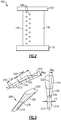
- Figure 2 illustrates an exemplary film cooled gaspath component 100.
- the exemplary film cooled gaspath component 100 is a stator, however one of skill in the art having the benefit of this disclosure will understand that the shaped film cooling holes described herein can be utilized in any type of film cooled component, and are not limited to stators.
- the film cooled component 100 includes a radially inward platform section 110, a radially outward platform section 120, and a vane portion 130 extending between the platforms 110, 120.
- the vane portion 130 includes a leading edge 132 positioned at a fore most edge of the vane portion 130, relative to an expected direction of fluid flow through the engine.
- the vane portion 130 includes a trailing edge 134 positioned at an aft most edge of the vane portion 130, relative to an expected direction of fluid flow through the engine.
- the film cooling holes 136 are connected to an internal plenum that receives a cooling fluid from either the radially outward platform 120 or the radially inward platform 110.
- the cooling fluid is pressurized and is forced out of the film cooling hole along the surface of the vane portion 130.
- the cooling fluid forms a layer of fluid, or a film, that adheres to the vane portion 130 and simultaneous cools the vane portion 130 and provides a buffer against hot gasses within the gaspath contacting the vane portion 130.
- FIG. 3 schematically illustrates a negative space of one exemplary film cooling hole 200.
- the film cooling hole 200 is a shaped film cooling holes.
- Shaped film cooling generally consist of a metering section 210 through the material of the gaspath component and a diffuser 220 to spread coolant over the surface of the gaspath component.
- the diffuser 220 is angled outward from the metering section 210, and expands the coolant.
- the diffuser 220 is angled at 7 degrees in the forward and lateral directions, and is referred to as a 7-7-7 film cooling hole.
- the diffuser 220 is angled at 10 degrees in the forward and lateral directions and is referred to as a 10-10-10 film cooling hole.
- the intentional offset between the diffuser 220 and the metering section 210 is applicable to both 7-7-7 holes and 10-10-10 holes, as well as any number of other film cooling hole styles, as will be understood by one of skill in the art.
- metering section 210 and the diffuser 220 are typically created using distinct machining actions.
- the holes are created using electrical discharge machining, although any alternative machining process can be used to similar effect.
- Conventional film cooling holes are designed such that a centerline 222 of the diffuser section, and an axis 212 of the metering section 210 are collinear.
- the centerline 222 of the diffuser 220 is defined as a line drawn from a midpoint of the opening intersecting with the metering section 210 to a midpoint of the opening in the exterior of the gas path component 100 (see Figure 1 ).
- the metering section 210 is generally cylindrical with a circular cross section parallel to an axis 212 defined by the cylinder.
- the metering section 210 can be formed with alternative cross sectional shapes, such as regular polygons, and function in a similar manner.
- the metering section 210 provides a through hole to the pressurized internal cavity and allows cooling fluid to be passed from the internal cavity to an exterior surface of the gas path component 100.
- the pressurized internal cavity is an impingement cavity
- the diffuser 220 is an angled hole with a wider opening 224 at an outlet end on the surface of the gas path component and a narrower opening 226, approximately the same size as the metering section 210 cross section interior to the gas path component.
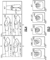
- Figures 4 and 5 schematically illustrate exemplary intentional offsets. Included in the illustration of Figure 5 is a key illustrating the terms "fore”, “aft", and “left” as they are applied to a given film cooling hole 200. Illustration A shows a film cooling hole 200 where the diffuser 220 and the metering section 210 are not offset.
- Illustration B shows a diffuser 220 that is offset left by one quarter of the diameter of the circular cross section of the metering portion 210.
- Illustration C shows a diffuser 220 that is offset forward by one quarter of the diameter of the circular cross section of the metering portion 210.
- Illustration D shows a diffuser 220 that is offset aftward by one quarter of the diameter of the metering portion 210.
- the intentional offset will result in the centerline 222 and the axis 210 being parallel, but not collinear.
- the offset can include a rotation of the diffuser section, and the centerline 222 and the axis 210 can be skew. While referred to herein by their relationship to the diameter of the circular cross section of the film cooling hole, one of skill in the art will understand that in the alternative examples using differently shaped metering sections, the diameter referred to is a hydraulic diameter.
- Figure 5 illustrates view of five different offsets at the surface of the gaspath component, with view 410 corresponding to illustration C of Figure 4 , view 420 corresponding to illustration B of Figure 4 , and 430 corresponding to illustration D of Figure 4 .
- view 415 is a combination of the offsets of views 410 and 420, alternately referred to as a fore-left offset.
- view 425 is a combination of views 420 and 430, alternately referred to as an aft-left offset.
- the diffuser 220 is not aligned with the cross section of the metering section 210. As a result, the flow of coolant through the metering section 210 into the diffuser 220, and thus creating the film on the gaspath component, is restricted to the shaded region 402.
- an offset can be made according to any known increment and achieve a desired purpose, with the magnitude of the offset and the angle of the offset being determined by the specific needs of the given application.
- Offsetting the diffuser 220 from the metering section 21 affects the disbursement of the cooling fluid along the surface of the gas path component including the film cooling hole 200, and has a corresponding effect on the efficacy of the film cooling.
- ideal cooling is achieved by shifting the diffuser 220 upstream relative to an expected fluid flow through the gas path of the turbine engine in which the gas path component is located. Shifting the diffuser 220 upstream increases the cooling capabilities of the film cooling system. In yet further examples, the diffuser 220 is shifted upstream by one quarter (25%) of the diameter of the metering section 210. In other examples, ideal cooling is achieved by shifting the diffuser 220 upstream by one eighth (12.5%) of the diameter of the metering section 210. In other examples, the diffuser 220 is shifted by an amount within the range of one eight to one quarter of the diameter of the metering section 210. In further alternative examples the diffuser 210 can be shifted upstream by any suitable amount, and the shifting is not limited to the range of one eight to one quarter of the diameter of the metering section 210.
- the blowing ratio is a number determined by ⁇ c U c / ⁇ ⁇ U ⁇ , where ⁇ c is the density of the cooling fluid, U c is the velocity of the cooling fluid passing through the coolant hole, ⁇ ⁇ is the density of the fluid in the gaspath, and U ⁇ is the velocity of the fluid in the gaspath.
- the film cooling provided is most effective when the blowing ratio is 1.0, with the cooling effectiveness decreasing the farther the film gest from the originating film cooling hole.
Landscapes
- Engineering & Computer Science (AREA)
- Mechanical Engineering (AREA)
- General Engineering & Computer Science (AREA)
- Turbine Rotor Nozzle Sealing (AREA)
Abstract
Description
- The present disclosure relates generally to film cooling holes, and specifically film cooing holes for gas path components of a gas turbine engine.
- Gas turbine engine include a compressor for compressing air, a combustor for mixing the compressed air with a fuel and igniting the mixture, and a turbine across which the resultant combustion products are expanded. As a result of the combustion, temperatures within the turbine engine gas path connecting each of the sections are extremely high. With some components the extreme temperatures require active cooling systems to keep the components exposed to the gaspath (referred to as gaspath components) below a maximum temperature and prevent damage to the component.
- In some exemplary gaspath components, such as rotors and blades, among others, the active cooling takes the form of a film cooling process. In film cooling, a series of holes eject a stream of coolant, such as air, along a surface of the gaspath component being cooled. The stream of coolant simultaneously cools the exterior surface and provides a buffer zone prevent at least a portion of the high temperature gasses in the gaspath from contacting the gaspath component. Film cooling can be utilized in conjunction with other active cooling systems, or on its own to cool a gaspath component depending on the needs of the gaspath component.
- In one exemplary embodiment a component for a gas turbine engine includes a body having at least one internal cooling cavity and a plurality of film cooling holes disposed along a first edge of the body, at least one of the film cooling holes including a metering section defining an axis, and a diffuser section having a centerline, the centerline of the diffuser section being offset from the axis of the metering section.
- In another exemplary embodiment of the above described component for a gas turbine engine the centerline of the diffuser section is offset from the axis of the metering section in an upstream direction.
- In another exemplary embodiment of any of the above described components for a gas turbine engine the centerline of the diffuser section is offset from the axis of the metering section by at least 12.5% of the diameter of the metering section.
- In another exemplary embodiment of any of the above described components for a gas turbine engine the centerline of the diffuser section is offset from the axis of the metering section by at least 25% of the diameter of the metering section.
- In another exemplary embodiment of any of the above described components for a gas turbine engine the centerline of the diffuser section is offset from the axis of the metering section by approximately 25% of the diameter of the metering section.
- In another exemplary embodiment of any of the above described components for a gas turbine engine wherein each of the film cooling holes has a blowing ratio of approximately 1.0.
- In another exemplary embodiment of any of the above described components for a gas turbine engine the metering section is cylindrical and has a circular cross section normal to the axis.
- In another exemplary embodiment of any of the above described components for a gas turbine engine the centerline of the diffuser section and the axis of the metering section are in parallel.
- In another exemplary embodiment of any of the above described components for a gas turbine engine the at least one film cooling hole is a 7-7-7 film cooling hole.
- In another exemplary embodiment of any of the above described components for a gas turbine engine wherein the at least one film cooling hole is a 10-10-10 film cooling hole.
- In another exemplary embodiment of any of the above described components for a gas turbine engine the upstream direction is a forward offset direction, relative to an expected fluid flow across an exterior surface of the body.
- An exemplary method for manufacturing a film cooled article includes offsetting a diffuser of at least one film cooling hole relative to a metering portion of the at least one film cooling hole.
- In a further example of the above described exemplary method for manufacturing a film cooled article the metering portion is manufactured in a first manufacturing step, and the diffuser section is manufactured in a second manufacturing step distinct form the first manufacturing step.
- In a further example of any of the above described exemplary methods for manufacturing a film cooled article the metering portion and the diffuser portion are simultaneously manufactured.
- In a further example of any of the above described exemplary methods for manufacturing a film cooled article offsetting the diffuser comprising manufacturing the diffuser such that a centerline of the diffuser is not collinear with an axis defined by the metering portion.
- A further example of any of the above described exemplary methods for manufacturing a film cooled article further includes maintaining the centerline of the diffuser in parallel with the axis defined by the metering portion.
- A further example of any of the above described exemplary methods for manufacturing a film cooled article further includes manufacturing the diffuser such that the centerline of the diffuser is skew relative to the axis defined by the metering portion.
- A further example of any of the above described exemplary methods for manufacturing a film cooled article further includes offsetting the diffuser upstream of the metering portion.
- A further example of any of the above described exemplary methods for manufacturing a film cooled article further includes offsetting the centerline of the diffuser section from the axis of the metering portion by at least 12.5% of the diameter of the metering section.
- A further example of any of the above described exemplary methods for manufacturing a film cooled article further includes offsetting the centerline of the diffuser section from the axis of the metering portion by at least 25% of the diameter of the metering section.
- A further example of any of the above described exemplary methods for manufacturing a film cooled article further includes offsetting the centerline of the diffuser section from the axis of the metering portion by approximately 25% of the diameter of the metering section.
- These and other features of the present invention can be best understood from the following specification and drawings, the following of which is a brief description.
-
-
Figure 1 schematically illustrates a gas turbine engine including multiple gaspath components. -
Figure 2 schematically illustrates an exemplary gaspath component including a series of film cooling holes. -
Figure 3 schematically illustrates a negative space of one exemplary film cooling hole. -
Figure 4 schematically illustrates multiple specific arrangements of the negative space illustrated inFigure 3 . -
Figure 5 schematically illustrates a surface view of multiple specific arrangements of a film cooling hole. -
Figure 1 schematically illustrates agas turbine engine 20. Thegas turbine engine 20 is disclosed herein as a two-spool turbofan that generally incorporates afan section 22, acompressor section 24, a combustor section 26 and aturbine section 28. Alternative engines might include an augmentor section (not shown) among other systems or features. Thefan section 22 drives air along a bypass flow path B in a bypass duct defined within anacelle 15, while thecompressor section 24 drives air along a core flow path C for compression and communication into the combustor section 26 then expansion through theturbine section 28. Although depicted as a two-spool turbofan gas turbine engine in the disclosed non-limiting embodiment, it should be understood that the concepts described herein are not limited to use with two-spool turbofans as the teachings may be applied to other types of turbine engines including three-spool architectures. - The
exemplary engine 20 generally includes alow speed spool 30 and ahigh speed spool 32 mounted for rotation about an engine central longitudinal axis A relative to an enginestatic structure 36 viaseveral bearing systems 38. It should be understood thatvarious bearing systems 38 at various locations may alternatively or additionally be provided, and the location ofbearing systems 38 may be varied as appropriate to the application. - The
low speed spool 30 generally includes aninner shaft 40 that interconnects afan 42, a first (or low)pressure compressor 44 and a first (or low)pressure turbine 46. Theinner shaft 40 is connected to thefan 42 through a speed change mechanism, which in exemplarygas turbine engine 20 is illustrated as a gearedarchitecture 48 to drive thefan 42 at a lower speed than thelow speed spool 30. Thehigh speed spool 32 includes anouter shaft 50 that interconnects a second (or high)pressure compressor 52 and a second (or high)pressure turbine 54. Acombustor 56 is arranged inexemplary gas turbine 20 between thehigh pressure compressor 52 and thehigh pressure turbine 54. Amid-turbine frame 57 of the enginestatic structure 36 is arranged generally between thehigh pressure turbine 54 and thelow pressure turbine 46. Themid-turbine frame 57 further supports bearingsystems 38 in theturbine section 28. Theinner shaft 40 and theouter shaft 50 are concentric and rotate viabearing systems 38 about the engine central longitudinal axis A which is collinear with their longitudinal axes. - The core airflow is compressed by the
low pressure compressor 44 then thehigh pressure compressor 52, mixed and burned with fuel in thecombustor 56, then expanded over thehigh pressure turbine 54 andlow pressure turbine 46. Themid-turbine frame 57 includesairfoils 59 which are in the core airflow path C. Theturbines low speed spool 30 andhigh speed spool 32 in response to the expansion. It will be appreciated that each of the positions of thefan section 22,compressor section 24, combustor section 26,turbine section 28, and fandrive gear system 48 may be varied. For example,gear system 48 may be located aft of combustor section 26 or even aft ofturbine section 28, andfan section 22 may be positioned forward or aft of the location ofgear system 48. - The
engine 20 in one example is a high-bypass geared aircraft engine. In a further example, theengine 20 bypass ratio is greater than about six, with an example embodiment being greater than about ten, the gearedarchitecture 48 is an epicyclic gear train, such as a planetary gear system or other gear system, with a gear reduction ratio of greater than about 2.3 and thelow pressure turbine 46 has a pressure ratio that is greater than about five. In one disclosed embodiment, theengine 20 bypass ratio is greater than about ten, the fan diameter is significantly larger than that of thelow pressure compressor 44, and thelow pressure turbine 46 has a pressure ratio that is greater than about five.Low pressure turbine 46 pressure ratio is pressure measured prior to inlet oflow pressure turbine 46 as related to the pressure at the outlet of thelow pressure turbine 46 prior to an exhaust nozzle. The gearedarchitecture 48 may be an epicycle gear train, such as a planetary gear system or other gear system, with a gear reduction ratio of greater than about 2.3:1. It should be understood, however, that the above parameters are only exemplary of one embodiment of a geared architecture engine and that the present invention is applicable to other gas turbine engines including direct drive turbofans. - A significant amount of thrust is provided by the bypass flow B due to the high bypass ratio. The
fan section 22 of theengine 20 is designed for a particular flight condition -- typically cruise at about 0.8 Mach and about 35,000 feet (10,668 meters). The flight condition of 0.8 Mach and 35,000 ft (10,668 m), with the engine at its best fuel consumption - also known as "bucket cruise Thrust Specific Fuel Consumption ('TSFC')" - is the industry standard parameter of lbm of fuel being burned divided by lbf of thrust the engine produces at that minimum point. "Low fan pressure ratio" is the pressure ratio across the fan blade alone, without a Fan Exit Guide Vane ("FEGV") system. The low fan pressure ratio as disclosed herein according to one non-limiting embodiment is less than about 1.45. "Low corrected fan tip speed" is the actual fan tip speed in ft/sec divided by an industry standard temperature correction of [(Tram °R) / (518.7 °R)]0.5 (where °R = K x 9/5). The "Low corrected fan tip speed" as disclosed herein according to one non-limiting embodiment is less than about 1150 ft / second (350.5 m/s). - In order to compensate for the extreme temperatures generated by the combustion, gaspath components, such as the blades and stators at an inlet of the
turbine section 28 include active cooling systems. Among other cooling techniques the active cooling systems utilize a film cooling technique. - With continued reference to
Figure 1 ,Figure 2 illustrates an exemplary film cooledgaspath component 100. The exemplary film cooledgaspath component 100 is a stator, however one of skill in the art having the benefit of this disclosure will understand that the shaped film cooling holes described herein can be utilized in any type of film cooled component, and are not limited to stators. - The film cooled
component 100 includes a radiallyinward platform section 110, a radiallyoutward platform section 120, and avane portion 130 extending between theplatforms vane portion 130 includes aleading edge 132 positioned at a fore most edge of thevane portion 130, relative to an expected direction of fluid flow through the engine. Similarly, thevane portion 130 includes a trailing edge 134 positioned at an aft most edge of thevane portion 130, relative to an expected direction of fluid flow through the engine. - Along the
leading edge 132 are multiple rows of film cooling holes 136. The film cooling holes 136 are connected to an internal plenum that receives a cooling fluid from either the radiallyoutward platform 120 or the radiallyinward platform 110. The cooling fluid is pressurized and is forced out of the film cooling hole along the surface of thevane portion 130. The cooling fluid forms a layer of fluid, or a film, that adheres to thevane portion 130 and simultaneous cools thevane portion 130 and provides a buffer against hot gasses within the gaspath contacting thevane portion 130. - With continued reference to
Figures 1 and2, Figure 3 schematically illustrates a negative space of one exemplaryfilm cooling hole 200. Thefilm cooling hole 200 is a shaped film cooling holes. Shaped film cooling generally consist of ametering section 210 through the material of the gaspath component and adiffuser 220 to spread coolant over the surface of the gaspath component. In order to spread the coolant thediffuser 220 is angled outward from themetering section 210, and expands the coolant. In one example thediffuser 220 is angled at 7 degrees in the forward and lateral directions, and is referred to as a 7-7-7 film cooling hole. In an alternate example, thediffuser 220 is angled at 10 degrees in the forward and lateral directions and is referred to as a 10-10-10 film cooling hole. The intentional offset between thediffuser 220 and themetering section 210 is applicable to both 7-7-7 holes and 10-10-10 holes, as well as any number of other film cooling hole styles, as will be understood by one of skill in the art. - These
metering section 210 and thediffuser 220 are typically created using distinct machining actions. In some examples the holes are created using electrical discharge machining, although any alternative machining process can be used to similar effect. Conventional film cooling holes are designed such that acenterline 222 of the diffuser section, and anaxis 212 of themetering section 210 are collinear. Thecenterline 222 of thediffuser 220 is defined as a line drawn from a midpoint of the opening intersecting with themetering section 210 to a midpoint of the opening in the exterior of the gas path component 100 (seeFigure 1 ). - In the illustrated example, the
metering section 210 is generally cylindrical with a circular cross section parallel to anaxis 212 defined by the cylinder. In alternative examples, themetering section 210 can be formed with alternative cross sectional shapes, such as regular polygons, and function in a similar manner. Themetering section 210 provides a through hole to the pressurized internal cavity and allows cooling fluid to be passed from the internal cavity to an exterior surface of thegas path component 100. In some examples, the pressurized internal cavity is an impingement cavity - The
diffuser 220 is an angled hole with awider opening 224 at an outlet end on the surface of the gas path component and anarrower opening 226, approximately the same size as themetering section 210 cross section interior to the gas path component. By aligning theaxis 212 of themetering section 220 with acenterline 222 of thediffuser 220, thediffuser 220 is able to expand and direct the cooling gas emitted from themetering section 220 and thereby enhance the film cooling layer. - Since the
metering section 210 and thediffuser 220 are machined into the gas path component via separate machining actions, it is possible to include an intentional offset between theaxis 212 of themetering section 210 and thecenterline 222 of thediffuser 220. With continued reference toFigure 3 , and with like numerals indicating like elements,Figures 4 and 5 schematically illustrate exemplary intentional offsets. Included in the illustration ofFigure 5 is a key illustrating the terms "fore", "aft", and "left" as they are applied to a givenfilm cooling hole 200. Illustration A shows afilm cooling hole 200 where thediffuser 220 and themetering section 210 are not offset. Illustration B shows adiffuser 220 that is offset left by one quarter of the diameter of the circular cross section of themetering portion 210. Illustration C shows adiffuser 220 that is offset forward by one quarter of the diameter of the circular cross section of themetering portion 210. Illustration D shows adiffuser 220 that is offset aftward by one quarter of the diameter of themetering portion 210. In some examples, the intentional offset will result in thecenterline 222 and theaxis 210 being parallel, but not collinear. In other examples, the offset can include a rotation of the diffuser section, and thecenterline 222 and theaxis 210 can be skew. While referred to herein by their relationship to the diameter of the circular cross section of the film cooling hole, one of skill in the art will understand that in the alternative examples using differently shaped metering sections, the diameter referred to is a hydraulic diameter. - In a similar vein,
Figure 5 illustrates view of five different offsets at the surface of the gaspath component, withview 410 corresponding to illustration C ofFigure 4 , view 420 corresponding to illustration B ofFigure 4 , and 430 corresponding to illustration D ofFigure 4 . It is also recognized that any of the offsets described above can be combined with another offset. By way of example,view 415 is a combination of the offsets ofviews view 425 is a combination ofviews diffuser 220 is not aligned with the cross section of themetering section 210. As a result, the flow of coolant through themetering section 210 into thediffuser 220, and thus creating the film on the gaspath component, is restricted to the shadedregion 402. - Further, while illustrated in the exemplary embodiments as 90 degree increments for the offsets, one of skill in the art will understand that an offset can be made according to any known increment and achieve a desired purpose, with the magnitude of the offset and the angle of the offset being determined by the specific needs of the given application.
- Offsetting the
diffuser 220 from the metering section 21 affects the disbursement of the cooling fluid along the surface of the gas path component including thefilm cooling hole 200, and has a corresponding effect on the efficacy of the film cooling. - In some examples, such as the illustrated aft shifts of
Figures 4 and 5 , ideal cooling is achieved by shifting thediffuser 220 upstream relative to an expected fluid flow through the gas path of the turbine engine in which the gas path component is located. Shifting thediffuser 220 upstream increases the cooling capabilities of the film cooling system. In yet further examples, thediffuser 220 is shifted upstream by one quarter (25%) of the diameter of themetering section 210. In other examples, ideal cooling is achieved by shifting thediffuser 220 upstream by one eighth (12.5%) of the diameter of themetering section 210. In other examples, thediffuser 220 is shifted by an amount within the range of one eight to one quarter of the diameter of themetering section 210. In further alternative examples thediffuser 210 can be shifted upstream by any suitable amount, and the shifting is not limited to the range of one eight to one quarter of the diameter of themetering section 210. - Another factor that impacts the effectiveness of the cooling provided by any given film cooling hole is the blowing ratio of the cooling hole. The blowing ratio is a number determined by ρcU c/ρ ∞ U ∞, where ρc is the density of the cooling fluid, U c is the velocity of the cooling fluid passing through the coolant hole, ρ ∞ is the density of the fluid in the gaspath, and U ∞ is the velocity of the fluid in the gaspath. In some examples, the film cooling provided is most effective when the blowing ratio is 1.0, with the cooling effectiveness decreasing the farther the film gest from the originating film cooling hole.
- It is further understood that any of the above described concepts can be used alone or in combination with any or all of the other above described concepts. Although an embodiment of this invention has been disclosed, a worker of ordinary skill in this art would recognize that certain modifications would come within the scope of this invention. For that reason, the following claims should be studied to determine the true scope and content of this invention.
Claims (15)
- A component (100) for a gas turbine engine (20) comprising:a body (130) having at least one internal cooling cavity; anda plurality of film cooling holes (136, 200) disposed along a first edge (132) of said body (130), at least one of the film cooling holes (136, 200) including a metering section (210) defining an axis (212), and a diffuser section (220) having a centerline (222), the centerline (22) of the diffuser section (220) being offset from the axis (212) of the metering section (210).
- The component (100) of claim 1, wherein the centerline (222) of the diffuser section (220) is offset from the axis (212) of the metering section (210) in an upstream direction, optionally wherein the centerline (222) of the diffuser section (220) is offset from the axis (212) of the metering section (210) by at least 12.5% of the diameter of the metering section (210), at least 25% of the diameter of the metering section (210), or approximately 25% of the diameter of the metering section (210).
- The component (100) of claim 1 or 2, wherein each of the film cooling holes (136, 200) has a blowing ratio of approximately 1.0.
- The component (100) of claim 1, 2 or 3, wherein the metering section (210) is cylindrical and has a circular cross section normal to the axis (212).
- The component (100) of any preceding claim, wherein the centerline (222) of the diffuser section (220) and the axis (212) of the metering section (210) are in parallel.
- The component (100) of any preceding claim, wherein the at least one film cooling hole (136, 200) is a 7-7-7 film cooling hole.
- The component (100) of any of claims 1 to 5, wherein the at least one film cooling hole (136, 200) is a 10-10-10 film cooling hole (136, 200).
- The component (100) of any preceding claim, wherein the upstream direction is a forward offset direction, relative to an expected fluid flow across an exterior surface of the body (130).
- A method for manufacturing a film cooled article (100) comprising:offsetting a diffuser (220) of at least one film cooling hole (136, 200) relative to a metering portion (210) of the at least one film cooling hole (136, 200).
- The method of claim 9, wherein said metering portion (210) is manufactured in a first manufacturing step, and said diffuser section (220) is manufactured in a second manufacturing step distinct form said first manufacturing step.
- The method of claim 9, wherein said metering portion (210) and said diffuser portion (220) are simultaneously manufactured.
- The method of claim 9, 10 or 11, wherein offsetting the diffuser (220) comprising manufacturing the diffuser (220) such that a centerline (222) of the diffuser (220) is not collinear with an axis (212) defined by the metering portion (210).
- The method of claim 12, further comprising manufacturing the diffuser (220) such that the centerline (222) of the diffuser (220) is skew relative to the axis (212) defined by the metering portion (210).
- The method of claim 12, further comprising maintaining the centerline (222) of the diffuser (220) in parallel with the axis (212) defined by the metering portion (210).
- The method of claim 12 or 13, further comprising offsetting the diffuser (220) upstream of the metering portion (210), optionally further comprising offsetting the centerline (222) of the diffuser section (220) from the axis (212) of the metering portion (210) by at least 12.5% of the diameter of the metering section (210), at least 25% of the diameter of the metering section (210), or approximately 25% of the diameter of the metering section (210).
Applications Claiming Priority (1)
| Application Number | Priority Date | Filing Date | Title |
|---|---|---|---|
| US201562258097P | 2015-11-20 | 2015-11-20 |
Publications (2)
| Publication Number | Publication Date |
|---|---|
| EP3179040A1 true EP3179040A1 (en) | 2017-06-14 |
| EP3179040B1 EP3179040B1 (en) | 2021-07-14 |
Family
ID=57326330
Family Applications (1)
| Application Number | Title | Priority Date | Filing Date |
|---|---|---|---|
| EP16199208.6A Revoked EP3179040B1 (en) | 2015-11-20 | 2016-11-16 | Component for a gas turbine engine and corresponding a method of manufacturing a film-cooled article |
Country Status (2)
| Country | Link |
|---|---|
| US (1) | US10392943B2 (en) |
| EP (1) | EP3179040B1 (en) |
Cited By (2)
| Publication number | Priority date | Publication date | Assignee | Title |
|---|---|---|---|---|
| EP3415257A1 (en) * | 2017-06-16 | 2018-12-19 | United Technologies Corporation | Systems and methods for manufacturing film cooling hole diffuser portion and film cooling hole |
| EP4134516A1 (en) * | 2021-08-13 | 2023-02-15 | Raytheon Technologies Corporation | Apparatuses for a turbine engine |
Families Citing this family (3)
| Publication number | Priority date | Publication date | Assignee | Title |
|---|---|---|---|---|
| US10844729B2 (en) * | 2018-04-05 | 2020-11-24 | Raytheon Technologies Corporation | Turbine vane for gas turbine engine |
| US11965429B1 (en) | 2023-09-22 | 2024-04-23 | Ge Infrastructure Technology Llc | Turbomachine component with film-cooling hole with hood extending from wall outer surface |
| JP2025117176A (en) * | 2024-01-30 | 2025-08-12 | 本田技研工業株式会社 | Wall member and manufacturing method thereof |
Citations (3)
| Publication number | Priority date | Publication date | Assignee | Title |
|---|---|---|---|---|
| EP0227582A2 (en) * | 1985-12-23 | 1987-07-01 | United Technologies Corporation | Improved film cooling passages with step diffuser |
| US8057180B1 (en) * | 2008-11-07 | 2011-11-15 | Florida Turbine Technologies, Inc. | Shaped film cooling hole for turbine airfoil |
| EP2574726A2 (en) * | 2011-09-27 | 2013-04-03 | General Electric Company | Offset counterbore for airfoil cooling hole |
Family Cites Families (27)
| Publication number | Priority date | Publication date | Assignee | Title |
|---|---|---|---|---|
| US4197443A (en) | 1977-09-19 | 1980-04-08 | General Electric Company | Method and apparatus for forming diffused cooling holes in an airfoil |
| US4762464A (en) | 1986-11-13 | 1988-08-09 | Chromalloy Gas Turbine Corporation | Airfoil with diffused cooling holes and method and apparatus for making the same |
| US4819325A (en) | 1987-06-01 | 1989-04-11 | Technical Manufacturing Systems, Inc. | Method of forming electro-discharge machining electrode |
| GB2244673B (en) | 1990-06-05 | 1993-09-01 | Rolls Royce Plc | A perforated sheet and a method of making the same |
| US6092982A (en) | 1996-05-28 | 2000-07-25 | Kabushiki Kaisha Toshiba | Cooling system for a main body used in a gas stream |
| US6368060B1 (en) | 2000-05-23 | 2002-04-09 | General Electric Company | Shaped cooling hole for an airfoil |
| US6984100B2 (en) | 2003-06-30 | 2006-01-10 | General Electric Company | Component and turbine assembly with film cooling |
| US6897401B2 (en) | 2003-07-31 | 2005-05-24 | United Technologies Corporation | Non-separating diffuser for holes produced by a two step process |
| US6969817B2 (en) * | 2003-10-15 | 2005-11-29 | General Electric Company | Apparatus and method for machining in confined spaces |
| US8587798B2 (en) | 2004-07-30 | 2013-11-19 | Hewlett-Packard Development Company, L.P. | Replacement component for a printing device |
| JP4931507B2 (en) | 2005-07-26 | 2012-05-16 | スネクマ | Cooling flow path formed in the wall |
| GB2438861A (en) | 2006-06-07 | 2007-12-12 | Rolls Royce Plc | Film-cooled component, eg gas turbine engine blade or vane |
| US7820267B2 (en) | 2007-08-20 | 2010-10-26 | Honeywell International Inc. | Percussion drilled shaped through hole and method of forming |
| US20090074588A1 (en) | 2007-09-19 | 2009-03-19 | Siemens Power Generation, Inc. | Airfoil with cooling hole having a flared section |
| US8092176B2 (en) | 2008-09-16 | 2012-01-10 | Siemens Energy, Inc. | Turbine airfoil cooling system with curved diffusion film cooling hole |
| DE102009007164A1 (en) | 2009-02-03 | 2010-08-12 | Rolls-Royce Deutschland Ltd & Co Kg | A method of forming a cooling air opening in a wall of a gas turbine combustor and combustor wall made by the method |
| US8925201B2 (en) * | 2009-06-29 | 2015-01-06 | Pratt & Whitney Canada Corp. | Method and apparatus for providing rotor discs |
| EP2292372B1 (en) | 2009-08-17 | 2012-10-03 | Siemens Aktiengesellschaft | Method for making a hole using different laser positions |
| US8905713B2 (en) * | 2010-05-28 | 2014-12-09 | General Electric Company | Articles which include chevron film cooling holes, and related processes |
| US8672613B2 (en) * | 2010-08-31 | 2014-03-18 | General Electric Company | Components with conformal curved film holes and methods of manufacture |
| JP6019578B2 (en) | 2011-12-15 | 2016-11-02 | 株式会社Ihi | Turbine blade |
| US8865095B2 (en) | 2011-12-20 | 2014-10-21 | Solvay Sa | Process for producing sodium bicarbonate |
| US9273560B2 (en) | 2012-02-15 | 2016-03-01 | United Technologies Corporation | Gas turbine engine component with multi-lobed cooling hole |
| US9376920B2 (en) | 2012-09-28 | 2016-06-28 | United Technologies Corporation | Gas turbine engine cooling hole with circular exit geometry |
| US20140161585A1 (en) | 2012-12-10 | 2014-06-12 | General Electric Company | Turbo-machine component and method |
| US11021965B2 (en) * | 2016-05-19 | 2021-06-01 | Honeywell International Inc. | Engine components with cooling holes having tailored metering and diffuser portions |
| US11286787B2 (en) * | 2016-09-15 | 2022-03-29 | Raytheon Technologies Corporation | Gas turbine engine airfoil with showerhead cooling holes near leading edge |
-
2016
- 2016-11-16 EP EP16199208.6A patent/EP3179040B1/en not_active Revoked
- 2016-11-18 US US15/355,173 patent/US10392943B2/en active Active
Patent Citations (3)
| Publication number | Priority date | Publication date | Assignee | Title |
|---|---|---|---|---|
| EP0227582A2 (en) * | 1985-12-23 | 1987-07-01 | United Technologies Corporation | Improved film cooling passages with step diffuser |
| US8057180B1 (en) * | 2008-11-07 | 2011-11-15 | Florida Turbine Technologies, Inc. | Shaped film cooling hole for turbine airfoil |
| EP2574726A2 (en) * | 2011-09-27 | 2013-04-03 | General Electric Company | Offset counterbore for airfoil cooling hole |
Cited By (4)
| Publication number | Priority date | Publication date | Assignee | Title |
|---|---|---|---|---|
| EP3415257A1 (en) * | 2017-06-16 | 2018-12-19 | United Technologies Corporation | Systems and methods for manufacturing film cooling hole diffuser portion and film cooling hole |
| US10773344B2 (en) | 2017-06-16 | 2020-09-15 | Raytheon Technologies Corporation | Systems and methods for manufacturing film cooling hole diffuser portion |
| US11407065B2 (en) | 2017-06-16 | 2022-08-09 | Raytheon Corporation Inc. | Systems and methods for manufacturing film cooling hole diffuser portion |
| EP4134516A1 (en) * | 2021-08-13 | 2023-02-15 | Raytheon Technologies Corporation | Apparatuses for a turbine engine |
Also Published As
| Publication number | Publication date |
|---|---|
| EP3179040B1 (en) | 2021-07-14 |
| US10392943B2 (en) | 2019-08-27 |
| US20180230811A1 (en) | 2018-08-16 |
Similar Documents
| Publication | Publication Date | Title |
|---|---|---|
| US11661853B2 (en) | Airfoil tip pocket with augmentation features | |
| US11407065B2 (en) | Systems and methods for manufacturing film cooling hole diffuser portion | |
| US11143039B2 (en) | Turbine engine component including an axially aligned skin core passage interrupted by a pedestal | |
| US9995147B2 (en) | Blade tip cooling arrangement | |
| US20200200027A1 (en) | Multiple injector holes for gas turbine engine vane | |
| US10830070B2 (en) | Endwall countouring trench | |
| US10982552B2 (en) | Gas turbine engine component with film cooling hole | |
| EP3034793B1 (en) | Gas turbine engine component with increased cooling capacity | |
| EP2956646B1 (en) | Component for a gas turbine engine and corresponding method of forming a cooling hole | |
| EP3179040B1 (en) | Component for a gas turbine engine and corresponding a method of manufacturing a film-cooled article | |
| US20160047251A1 (en) | Cooling hole having unique meter portion | |
| EP3266983B1 (en) | Cooling system for an airfoil of a gas powered turbine | |
| US10968751B2 (en) | Turbine blade cooling hole arrangement | |
| US9957814B2 (en) | Gas turbine engine component with film cooling hole with accumulator | |
| US10280756B2 (en) | Gas turbine engine airfoil | |
| US20160003152A1 (en) | Gas turbine engine multi-vaned stator cooling configuration | |
| US20160186576A1 (en) | Large-footprint turbine cooling hole | |
| US20160208627A1 (en) | Cooling feed orifices | |
| US9988911B2 (en) | Gas turbine engine component paired film cooling holes | |
| US20190040796A1 (en) | Gas turbine engine cooling arrangement | |
| EP3907373B1 (en) | Turbine blade cooling hole combination |
Legal Events
| Date | Code | Title | Description |
|---|---|---|---|
| PUAI | Public reference made under article 153(3) epc to a published international application that has entered the european phase |
Free format text: ORIGINAL CODE: 0009012 |
|
| STAA | Information on the status of an ep patent application or granted ep patent |
Free format text: STATUS: THE APPLICATION HAS BEEN PUBLISHED |
|
| AK | Designated contracting states |
Kind code of ref document: A1 Designated state(s): AL AT BE BG CH CY CZ DE DK EE ES FI FR GB GR HR HU IE IS IT LI LT LU LV MC MK MT NL NO PL PT RO RS SE SI SK SM TR |
|
| AX | Request for extension of the european patent |
Extension state: BA ME |
|
| STAA | Information on the status of an ep patent application or granted ep patent |
Free format text: STATUS: REQUEST FOR EXAMINATION WAS MADE |
|
| RAP1 | Party data changed (applicant data changed or rights of an application transferred) |
Owner name: THE PENN STATE RESEARCH FOUNDATION Owner name: UNITED TECHNOLOGIES CORPORATION |
|
| RIN1 | Information on inventor provided before grant (corrected) |
Inventor name: HAYDT, SHANE Inventor name: LYNCH, STEPHEN Inventor name: LEWIS, SCOTT D. |
|
| 17P | Request for examination filed |
Effective date: 20171214 |
|
| RBV | Designated contracting states (corrected) |
Designated state(s): AL AT BE BG CH CY CZ DE DK EE ES FI FR GB GR HR HU IE IS IT LI LT LU LV MC MK MT NL NO PL PT RO RS SE SI SK SM TR |
|
| RIN1 | Information on inventor provided before grant (corrected) |
Inventor name: LEWIS, SCOTT D. Inventor name: HAYDT, SHANE Inventor name: LYNCH, STEPHEN |
|
| GRAP | Despatch of communication of intention to grant a patent |
Free format text: ORIGINAL CODE: EPIDOSNIGR1 |
|
| STAA | Information on the status of an ep patent application or granted ep patent |
Free format text: STATUS: GRANT OF PATENT IS INTENDED |
|
| INTG | Intention to grant announced |
Effective date: 20210128 |
|
| RAP1 | Party data changed (applicant data changed or rights of an application transferred) |
Owner name: RAYTHEON TECHNOLOGIES CORPORATION Owner name: THE PENN STATE RESEARCH FOUNDATION |
|
| GRAS | Grant fee paid |
Free format text: ORIGINAL CODE: EPIDOSNIGR3 |
|
| GRAA | (expected) grant |
Free format text: ORIGINAL CODE: 0009210 |
|
| STAA | Information on the status of an ep patent application or granted ep patent |
Free format text: STATUS: THE PATENT HAS BEEN GRANTED |
|
| AK | Designated contracting states |
Kind code of ref document: B1 Designated state(s): AL AT BE BG CH CY CZ DE DK EE ES FI FR GB GR HR HU IE IS IT LI LT LU LV MC MK MT NL NO PL PT RO RS SE SI SK SM TR |
|
| REG | Reference to a national code |
Ref country code: GB Ref legal event code: FG4D |
|
| REG | Reference to a national code |
Ref country code: IE Ref legal event code: FG4D |
|
| REG | Reference to a national code |
Ref country code: DE Ref legal event code: R096 Ref document number: 602016060553 Country of ref document: DE |
|
| REG | Reference to a national code |
Ref country code: AT Ref legal event code: REF Ref document number: 1410809 Country of ref document: AT Kind code of ref document: T Effective date: 20210815 |
|
| REG | Reference to a national code |
Ref country code: LT Ref legal event code: MG9D |
|
| REG | Reference to a national code |
Ref country code: NL Ref legal event code: MP Effective date: 20210714 |
|
| REG | Reference to a national code |
Ref country code: AT Ref legal event code: MK05 Ref document number: 1410809 Country of ref document: AT Kind code of ref document: T Effective date: 20210714 |
|
| PG25 | Lapsed in a contracting state [announced via postgrant information from national office to epo] |
Ref country code: SE Free format text: LAPSE BECAUSE OF FAILURE TO SUBMIT A TRANSLATION OF THE DESCRIPTION OR TO PAY THE FEE WITHIN THE PRESCRIBED TIME-LIMIT Effective date: 20210714 Ref country code: RS Free format text: LAPSE BECAUSE OF FAILURE TO SUBMIT A TRANSLATION OF THE DESCRIPTION OR TO PAY THE FEE WITHIN THE PRESCRIBED TIME-LIMIT Effective date: 20210714 Ref country code: HR Free format text: LAPSE BECAUSE OF FAILURE TO SUBMIT A TRANSLATION OF THE DESCRIPTION OR TO PAY THE FEE WITHIN THE PRESCRIBED TIME-LIMIT Effective date: 20210714 Ref country code: LT Free format text: LAPSE BECAUSE OF FAILURE TO SUBMIT A TRANSLATION OF THE DESCRIPTION OR TO PAY THE FEE WITHIN THE PRESCRIBED TIME-LIMIT Effective date: 20210714 Ref country code: AT Free format text: LAPSE BECAUSE OF FAILURE TO SUBMIT A TRANSLATION OF THE DESCRIPTION OR TO PAY THE FEE WITHIN THE PRESCRIBED TIME-LIMIT Effective date: 20210714 Ref country code: BG Free format text: LAPSE BECAUSE OF FAILURE TO SUBMIT A TRANSLATION OF THE DESCRIPTION OR TO PAY THE FEE WITHIN THE PRESCRIBED TIME-LIMIT Effective date: 20211014 Ref country code: NL Free format text: LAPSE BECAUSE OF FAILURE TO SUBMIT A TRANSLATION OF THE DESCRIPTION OR TO PAY THE FEE WITHIN THE PRESCRIBED TIME-LIMIT Effective date: 20210714 Ref country code: PT Free format text: LAPSE BECAUSE OF FAILURE TO SUBMIT A TRANSLATION OF THE DESCRIPTION OR TO PAY THE FEE WITHIN THE PRESCRIBED TIME-LIMIT Effective date: 20211115 Ref country code: NO Free format text: LAPSE BECAUSE OF FAILURE TO SUBMIT A TRANSLATION OF THE DESCRIPTION OR TO PAY THE FEE WITHIN THE PRESCRIBED TIME-LIMIT Effective date: 20211014 Ref country code: FI Free format text: LAPSE BECAUSE OF FAILURE TO SUBMIT A TRANSLATION OF THE DESCRIPTION OR TO PAY THE FEE WITHIN THE PRESCRIBED TIME-LIMIT Effective date: 20210714 Ref country code: ES Free format text: LAPSE BECAUSE OF FAILURE TO SUBMIT A TRANSLATION OF THE DESCRIPTION OR TO PAY THE FEE WITHIN THE PRESCRIBED TIME-LIMIT Effective date: 20210714 |
|
| PG25 | Lapsed in a contracting state [announced via postgrant information from national office to epo] |
Ref country code: PL Free format text: LAPSE BECAUSE OF FAILURE TO SUBMIT A TRANSLATION OF THE DESCRIPTION OR TO PAY THE FEE WITHIN THE PRESCRIBED TIME-LIMIT Effective date: 20210714 Ref country code: LV Free format text: LAPSE BECAUSE OF FAILURE TO SUBMIT A TRANSLATION OF THE DESCRIPTION OR TO PAY THE FEE WITHIN THE PRESCRIBED TIME-LIMIT Effective date: 20210714 Ref country code: GR Free format text: LAPSE BECAUSE OF FAILURE TO SUBMIT A TRANSLATION OF THE DESCRIPTION OR TO PAY THE FEE WITHIN THE PRESCRIBED TIME-LIMIT Effective date: 20211015 |
|
| REG | Reference to a national code |
Ref country code: DE Ref legal event code: R026 Ref document number: 602016060553 Country of ref document: DE |
|
| PLBI | Opposition filed |
Free format text: ORIGINAL CODE: 0009260 |
|
| PG25 | Lapsed in a contracting state [announced via postgrant information from national office to epo] |
Ref country code: DK Free format text: LAPSE BECAUSE OF FAILURE TO SUBMIT A TRANSLATION OF THE DESCRIPTION OR TO PAY THE FEE WITHIN THE PRESCRIBED TIME-LIMIT Effective date: 20210714 |
|
| PLAX | Notice of opposition and request to file observation + time limit sent |
Free format text: ORIGINAL CODE: EPIDOSNOBS2 |
|
| 26 | Opposition filed |
Opponent name: SAFRAN AIRCRAFT ENGINES Effective date: 20220413 |
|
| PG25 | Lapsed in a contracting state [announced via postgrant information from national office to epo] |
Ref country code: SM Free format text: LAPSE BECAUSE OF FAILURE TO SUBMIT A TRANSLATION OF THE DESCRIPTION OR TO PAY THE FEE WITHIN THE PRESCRIBED TIME-LIMIT Effective date: 20210714 Ref country code: SK Free format text: LAPSE BECAUSE OF FAILURE TO SUBMIT A TRANSLATION OF THE DESCRIPTION OR TO PAY THE FEE WITHIN THE PRESCRIBED TIME-LIMIT Effective date: 20210714 Ref country code: RO Free format text: LAPSE BECAUSE OF FAILURE TO SUBMIT A TRANSLATION OF THE DESCRIPTION OR TO PAY THE FEE WITHIN THE PRESCRIBED TIME-LIMIT Effective date: 20210714 Ref country code: EE Free format text: LAPSE BECAUSE OF FAILURE TO SUBMIT A TRANSLATION OF THE DESCRIPTION OR TO PAY THE FEE WITHIN THE PRESCRIBED TIME-LIMIT Effective date: 20210714 Ref country code: CZ Free format text: LAPSE BECAUSE OF FAILURE TO SUBMIT A TRANSLATION OF THE DESCRIPTION OR TO PAY THE FEE WITHIN THE PRESCRIBED TIME-LIMIT Effective date: 20210714 Ref country code: AL Free format text: LAPSE BECAUSE OF FAILURE TO SUBMIT A TRANSLATION OF THE DESCRIPTION OR TO PAY THE FEE WITHIN THE PRESCRIBED TIME-LIMIT Effective date: 20210714 |
|
| PG25 | Lapsed in a contracting state [announced via postgrant information from national office to epo] |
Ref country code: MC Free format text: LAPSE BECAUSE OF FAILURE TO SUBMIT A TRANSLATION OF THE DESCRIPTION OR TO PAY THE FEE WITHIN THE PRESCRIBED TIME-LIMIT Effective date: 20210714 |
|
| REG | Reference to a national code |
Ref country code: CH Ref legal event code: PL |
|
| PG25 | Lapsed in a contracting state [announced via postgrant information from national office to epo] |
Ref country code: LU Free format text: LAPSE BECAUSE OF NON-PAYMENT OF DUE FEES Effective date: 20211116 Ref country code: IT Free format text: LAPSE BECAUSE OF FAILURE TO SUBMIT A TRANSLATION OF THE DESCRIPTION OR TO PAY THE FEE WITHIN THE PRESCRIBED TIME-LIMIT Effective date: 20210714 Ref country code: BE Free format text: LAPSE BECAUSE OF NON-PAYMENT OF DUE FEES Effective date: 20211130 |
|
| REG | Reference to a national code |
Ref country code: BE Ref legal event code: MM Effective date: 20211130 |
|
| PLBB | Reply of patent proprietor to notice(s) of opposition received |
Free format text: ORIGINAL CODE: EPIDOSNOBS3 |
|
| PG25 | Lapsed in a contracting state [announced via postgrant information from national office to epo] |
Ref country code: IE Free format text: LAPSE BECAUSE OF NON-PAYMENT OF DUE FEES Effective date: 20211116 |
|
| PG25 | Lapsed in a contracting state [announced via postgrant information from national office to epo] |
Ref country code: HU Free format text: LAPSE BECAUSE OF FAILURE TO SUBMIT A TRANSLATION OF THE DESCRIPTION OR TO PAY THE FEE WITHIN THE PRESCRIBED TIME-LIMIT; INVALID AB INITIO Effective date: 20161116 |
|
| PG25 | Lapsed in a contracting state [announced via postgrant information from national office to epo] |
Ref country code: CY Free format text: LAPSE BECAUSE OF FAILURE TO SUBMIT A TRANSLATION OF THE DESCRIPTION OR TO PAY THE FEE WITHIN THE PRESCRIBED TIME-LIMIT Effective date: 20210714 |
|
| PG25 | Lapsed in a contracting state [announced via postgrant information from national office to epo] |
Ref country code: LI Free format text: LAPSE BECAUSE OF NON-PAYMENT OF DUE FEES Effective date: 20220630 Ref country code: CH Free format text: LAPSE BECAUSE OF NON-PAYMENT OF DUE FEES Effective date: 20220630 |
|
| RAP4 | Party data changed (patent owner data changed or rights of a patent transferred) |
Owner name: THE PENN STATE RESEARCH FOUNDATION Owner name: RTX CORPORATION |
|
| APBM | Appeal reference recorded |
Free format text: ORIGINAL CODE: EPIDOSNREFNO |
|
| APBP | Date of receipt of notice of appeal recorded |
Free format text: ORIGINAL CODE: EPIDOSNNOA2O |
|
| APAH | Appeal reference modified |
Free format text: ORIGINAL CODE: EPIDOSCREFNO |
|
| APBQ | Date of receipt of statement of grounds of appeal recorded |
Free format text: ORIGINAL CODE: EPIDOSNNOA3O |
|
| PG25 | Lapsed in a contracting state [announced via postgrant information from national office to epo] |
Ref country code: MK Free format text: LAPSE BECAUSE OF FAILURE TO SUBMIT A TRANSLATION OF THE DESCRIPTION OR TO PAY THE FEE WITHIN THE PRESCRIBED TIME-LIMIT Effective date: 20210714 |
|
| PG25 | Lapsed in a contracting state [announced via postgrant information from national office to epo] |
Ref country code: TR Free format text: LAPSE BECAUSE OF FAILURE TO SUBMIT A TRANSLATION OF THE DESCRIPTION OR TO PAY THE FEE WITHIN THE PRESCRIBED TIME-LIMIT Effective date: 20210714 |
|
| PG25 | Lapsed in a contracting state [announced via postgrant information from national office to epo] |
Ref country code: MT Free format text: LAPSE BECAUSE OF FAILURE TO SUBMIT A TRANSLATION OF THE DESCRIPTION OR TO PAY THE FEE WITHIN THE PRESCRIBED TIME-LIMIT Effective date: 20210714 |
|
| PGFP | Annual fee paid to national office [announced via postgrant information from national office to epo] |
Ref country code: DE Payment date: 20241022 Year of fee payment: 9 |
|
| PGFP | Annual fee paid to national office [announced via postgrant information from national office to epo] |
Ref country code: GB Payment date: 20241023 Year of fee payment: 9 |
|
| PGFP | Annual fee paid to national office [announced via postgrant information from national office to epo] |
Ref country code: FR Payment date: 20241022 Year of fee payment: 9 |
|
| APBU | Appeal procedure closed |
Free format text: ORIGINAL CODE: EPIDOSNNOA9O |
|
| REG | Reference to a national code |
Ref country code: DE Ref legal event code: R064 Ref document number: 602016060553 Country of ref document: DE Ref country code: DE Ref legal event code: R103 Ref document number: 602016060553 Country of ref document: DE |
|
| RDAF | Communication despatched that patent is revoked |
Free format text: ORIGINAL CODE: EPIDOSNREV1 |
|
| STAA | Information on the status of an ep patent application or granted ep patent |
Free format text: STATUS: PATENT REVOKED |
|
| RDAG | Patent revoked |
Free format text: ORIGINAL CODE: 0009271 |
|
| REG | Reference to a national code |
Ref country code: CH Ref legal event code: PL |
|
| REG | Reference to a national code |
Ref country code: DE Ref legal event code: R081 Ref document number: 602016060553 Country of ref document: DE Owner name: RTX CORPORATION (N.D.GES.D. STAATES DELAWARE),, US Free format text: FORMER OWNERS: RAYTHEON TECHNOLOGIES CORPORATION, FARMINGTON, CT, US; THE PENN STATE RESEARCH FOUNDATION, UNIVERSITY PARK, PA., US |
|
| 27W | Patent revoked |
Effective date: 20250721 |
|
| GBPR | Gb: patent revoked under art. 102 of the ep convention designating the uk as contracting state |
Effective date: 20250721 |