EP3179006A1 - L-profile shaped element, the use of same and a method for installing same - Google Patents
L-profile shaped element, the use of same and a method for installing same Download PDFInfo
- Publication number
- EP3179006A1 EP3179006A1 EP17152773.2A EP17152773A EP3179006A1 EP 3179006 A1 EP3179006 A1 EP 3179006A1 EP 17152773 A EP17152773 A EP 17152773A EP 3179006 A1 EP3179006 A1 EP 3179006A1
- Authority
- EP
- European Patent Office
- Prior art keywords
- shaped element
- profile shaped
- leg
- edge
- covering
- Prior art date
- Legal status (The legal status is an assumption and is not a legal conclusion. Google has not performed a legal analysis and makes no representation as to the accuracy of the status listed.)
- Granted
Links
Images



Classifications
-
- E—FIXED CONSTRUCTIONS
- E04—BUILDING
- E04C—STRUCTURAL ELEMENTS; BUILDING MATERIALS
- E04C2/00—Building elements of relatively thin form for the construction of parts of buildings, e.g. sheet materials, slabs, or panels
- E04C2/30—Building elements of relatively thin form for the construction of parts of buildings, e.g. sheet materials, slabs, or panels characterised by the shape or structure
-
- E—FIXED CONSTRUCTIONS
- E04—BUILDING
- E04F—FINISHING WORK ON BUILDINGS, e.g. STAIRS, FLOORS
- E04F11/00—Stairways, ramps, or like structures; Balustrades; Handrails
- E04F11/02—Stairways; Layouts thereof
- E04F11/09—Tread-and-riser units
-
- E—FIXED CONSTRUCTIONS
- E04—BUILDING
- E04F—FINISHING WORK ON BUILDINGS, e.g. STAIRS, FLOORS
- E04F11/00—Stairways, ramps, or like structures; Balustrades; Handrails
- E04F11/02—Stairways; Layouts thereof
- E04F11/104—Treads
- E04F11/16—Surfaces thereof; Protecting means for edges or corners thereof
-
- E—FIXED CONSTRUCTIONS
- E04—BUILDING
- E04F—FINISHING WORK ON BUILDINGS, e.g. STAIRS, FLOORS
- E04F11/00—Stairways, ramps, or like structures; Balustrades; Handrails
- E04F11/02—Stairways; Layouts thereof
- E04F11/104—Treads
- E04F11/1043—Treads with an upper layer of organic plastics with or without reinforcements or filling materials
-
- E—FIXED CONSTRUCTIONS
- E04—BUILDING
- E04F—FINISHING WORK ON BUILDINGS, e.g. STAIRS, FLOORS
- E04F11/00—Stairways, ramps, or like structures; Balustrades; Handrails
- E04F11/02—Stairways; Layouts thereof
- E04F11/104—Treads
- E04F11/16—Surfaces thereof; Protecting means for edges or corners thereof
- E04F11/17—Surfaces
-
- E—FIXED CONSTRUCTIONS
- E04—BUILDING
- E04F—FINISHING WORK ON BUILDINGS, e.g. STAIRS, FLOORS
- E04F15/00—Flooring
- E04F15/02—Flooring or floor layers composed of a number of similar elements
- E04F15/10—Flooring or floor layers composed of a number of similar elements of other materials, e.g. fibrous or chipped materials, organic plastics, magnesite tiles, hardboard, or with a top layer of other materials
- E04F15/105—Flooring or floor layers composed of a number of similar elements of other materials, e.g. fibrous or chipped materials, organic plastics, magnesite tiles, hardboard, or with a top layer of other materials of organic plastics with or without reinforcements or filling materials
-
- E—FIXED CONSTRUCTIONS
- E04—BUILDING
- E04F—FINISHING WORK ON BUILDINGS, e.g. STAIRS, FLOORS
- E04F19/00—Other details of constructional parts for finishing work on buildings
- E04F19/02—Borders; Finishing strips, e.g. beadings; Light coves
- E04F19/06—Borders; Finishing strips, e.g. beadings; Light coves specially designed for securing panels or masking the edges of wall- or floor-covering elements
- E04F19/061—Borders; Finishing strips, e.g. beadings; Light coves specially designed for securing panels or masking the edges of wall- or floor-covering elements used to finish off an edge or corner of a wall or floor covering area
-
- E—FIXED CONSTRUCTIONS
- E04—BUILDING
- E04F—FINISHING WORK ON BUILDINGS, e.g. STAIRS, FLOORS
- E04F2203/00—Specially structured or shaped covering, lining or flooring elements not otherwise provided for
- E04F2203/04—Specially structured or shaped covering, lining or flooring elements not otherwise provided for comprising a plurality of internal elongated cavities arranged in substantially parallel rows
-
- Y—GENERAL TAGGING OF NEW TECHNOLOGICAL DEVELOPMENTS; GENERAL TAGGING OF CROSS-SECTIONAL TECHNOLOGIES SPANNING OVER SEVERAL SECTIONS OF THE IPC; TECHNICAL SUBJECTS COVERED BY FORMER USPC CROSS-REFERENCE ART COLLECTIONS [XRACs] AND DIGESTS
- Y10—TECHNICAL SUBJECTS COVERED BY FORMER USPC
- Y10T—TECHNICAL SUBJECTS COVERED BY FORMER US CLASSIFICATION
- Y10T29/00—Metal working
- Y10T29/49—Method of mechanical manufacture
- Y10T29/49826—Assembling or joining
Definitions
- the invention relates to the L-profile shaped element for covering an edge of a terrace structure defined in the preamble of claim 1, to the use of such defined in the preamble of claim 12, and to the method for installing such defined in the preamble of claim 13, and to the terrace structure defined in the preamble of claim 14.
- edge strips in connection with floor or terrace structures formed from a composite material to finish the visual look.
- a problem in the use of the known edge strips is that they are easily loosened and seldom withstand intensive wear and use.
- stair structures Stairs have mainly been built from wood, concrete or metal.
- Known from publication US4951434 is a stair structure formed from plastic or carbon fiber, wherein the structure includes more than one step. The structure is formed by injection molding.
- DE202009013314U1 and US2006242916A1 disclose a corner profile for a terrace structure.
- An objective of the invention is to disclose a new type of an L-profile shaped element suitable for many purposes of use. Furthermore, an objective of the invention is to disclose a new manner of forming stair structures and terrace structures. In addition, an objective of the invention is to disclose a method for installing L-profile shaped elements to each other, e.g. in order to form stair structures.
- the L-profile shaped element, the uses thereof and the installation methods therefor according to the invention are characterized by what is presented in the claims.
- the invention is based on an L-profile shaped element.
- the L-profile shaped element is formed as a monolithic piece, and the L-profile shaped element includes a first and a second leg, wherein the legs are arranged to have substantially the same thicknesses, at least one edge of each leg is provided with joint parts functioning in substantially the same manner, and the element is turnable to a desired position.
- An L-profile shaped element means in this context a profile of any length having an L-shaped cross section.
- the dimensions of the L-profile shaped element, such as the length as well as the width and thickness of the legs, may vary depending on the application.
- the thicknesses of the legs as well as the widths of the inner and outer surfaces are predetermined and depend on the purpose of use of the L-profile shaped elements.
- the L-profile shaped element is preferably used as an angular element in order to form an angular structure.
- the L-profile shaped element preferably includes an interior angle and an exterior angle.
- joint parts functioning in the same manner are to be fitted to the edges of the legs, i.e. to the edges in the thickness direction, of the L-profile shaped element.
- a joint part is to function in the same manner in the interior as well as exterior of the L-profile shaped element, regardless which way around the element has been turned.
- the joint part may be shaped for a joint member, or it may function as one directly.
- the joint parts of the legs must be equally thick or disposed at the same height in the thickness direction of the leg, so that the legs of the elements to be joined are set flush with each other when joined together.
- the joint part may be selected according to the purpose of use. E.g. a groove or tongue structure or other suitable structure may be used as a joint part.
- the thickness of the leg of the L-profile shaped element is between 3 and 100 mm, preferably between 20 and 35 mm and more preferably between 25 and 30 mm.
- the difference in the thickness between the legs is less than 2mm, more preferably less than 1 mm.
- the width of the external dimension of at least one leg of the L-profile shaped element is between 30 and 280 mm, preferably between 40 and 250 mm and more preferably between 50 and 120 mm, and the width of the dimension of the inner sur- face is between 27 and 397 mm, preferably between 28 and 288 mm and in one preferred embodiment between 55 and 125 mm.
- the width of the external dimension of at least one leg of the L-profile shaped element is between 30 and 400 mm, preferably between 40 and 300 mm and more preferably between 80 and 150 mm, and the width of the dimension of the inner surface is between 27 and 397 mm, preferably between 28 and 288 mm and more preferably between 55 and 125 mm.
- the L-profile shaped element includes a first and a second leg, wherein the legs are arranged to have substantially different widths but substantially the same thicknesses.
- the width of the second leg is 1 to 13.3 times, preferably 1.1 to 7.5 times, more preferably 1.2 to 3 times and most preferably 1.5 to 1.7 times the width of the first leg.
- the L-profile shaped element includes a first and a second leg, wherein the legs are arranged to have substantially the same widths and substantially the same thicknesses. In this case the difference in the width of the legs is less than 2 mm, more preferably less than 1 mm.
- the L-profile shaped element is arranged to be joined from the thicknesswise end of at least one leg, which, at the same time, is the lengthwise face of the L-profile shaped element, by a joint part to at least one other element which may be e.g. another L-profile shaped element or an additional element to be connected to an L- profile shaped element, or another element.
- the joint part of the thicknesswise end of the leg is shaped for a joint member in order to facilitate the joining e.g. with another L-profile shaped element or another element.
- a monolithic interior angle is formed without joints between the inner surfaces of the legs.
- a monolithic exterior angle is formed without joints between the outer surfaces of the legs. This way, the surface is continuous for the part of the entire angular structure which is seamless and safe. In this manner a jointless angular element is provided.
- the patterning of the legs of the L-profile shaped element is arranged to be at least partially the same, which facilitates turning of the element.
- the patterning of both sides of the leg is arranged to be at least partially the same. Similar surfaces provide a harmonious look, regardless in which manner and which way around the element is installed.
- at least part of the surface of the leg is modified, e.g. by grooving.
- the top surface of the leg is at least partially smooth.
- the groove patterning or smooth surface provided to the legs is the same, but the area covered by the patterning may vary.
- the thicknesswise end surfaces of the legs need not be similar to the other side surfaces of the legs.
- the same surface patterning is provided on both sides of the exterior angle between the legs. In one embodiment of the invention the same surface patterning is provided on both sides of the interior angle between the legs. In one embodiment of the invention the same surface patterning is provided on both sides of the exterior angle and the interior angle between the legs.
- the surface patterning may vary according to the purpose of use, but preferably all surfaces of all legs have a functionally similar patterning.
- the leg is provided with a groove-ridge patterning.
- the leg is provided with a substantially smooth framing area which may serve as a decorative area or border at the edge of the leg.
- the leg is provided with a groove ridge patterning to provide the desired functionality to the surface of the leg and a substantially smooth border area and/or angular area to provide a decorative appearance to the surface of the leg.
- the surface patterning is provided to the surface of the leg without any such rises or elevations on which one may stumble or which may affect the safety e.g. in stair structures.
- At least one cavity structure is provided within at least one leg.
- the cavity structure may consist of one or several cavities, and the cavity may be a channel, opening or other cavity structure. If desired, the cavities may be filled with a suitable material, such as light, elastic, insulating or otherwise suitable material. In one embodiment the cavity is arranged to be elongated in the lengthwise direction of the leg. The cavities provide for control of the weight of the L-profile shaped element. The number or ratio of the cavities relative to the rest of the structure depends on the starting material used and the strength and/or load-carrying capacity desired for the element.
- a border is provided to at least one lengthwise edge of at least one leg.
- the lengthwise edge may be the lengthwise outer edge of the leg or the lengthwise inner edge of the leg, i.e. the lengthwise edge forming an angle with another leg.
- the up- and/or forward-projecting edge of the rise and the tread of a step to be formed from the elements can be bordered or covered.
- the width of the border may vary according to the purpose of use.
- the border is formed in connection with the manufacture of the L-profile shaped element, e.g. by extrusion or an additional extrusion step or alternatively by modifying or patterning the material of the element in a desired area.
- the border is provided to the L-profile shaped element symmetrically in such a manner that the element looks the same from different sides, when turned to a desired position.
- a border is provided to at least one edge in the width direction of at least one leg.
- a profile of a desired shape is used as the border.
- the border may be formed from the same material or from a different material.
- the border may be an integral part of the element according to the invention, or it may be separate and joined to the element.
- the border may serve as a decorative part.
- the border may be formed in connection with the manufacture of the L-profile shaped element.
- the border can be joined to the L-profile shaped element after the manufacture of the element or in connection with the installation of the element.
- the L-profile shaped element is formed by a forming method based on heat and pressure.
- the element is formed as a monolithic piece by extrusion.
- the L-profile shaped element is formed from a starting material which contains fiber-based and plastic-based components.
- the L-profile shaped element is formed from a composite material which contains fiber-based components and/or plastic-based components and is used as the starting material.
- the composite material is formed from one or several raw stocks or raw stock materials.
- the raw stock or raw stock material may contain any fiber-based, e.g. plant fiber-based, such as wood fiber, straw, reed or flax-based, or other fiber-based components and/or plastic-based components.
- the composite material may be in a shredded, granulate, agglomerate, crushed or equivalent form.
- the composite material is a wood-plastic composite material.
- the wood-plastic composite material is formed from raw stocks which contain mainly fiber-based, e.g. paper-based, material, and plastic-based material, such as thermo- setting or thermoplastic resin.
- a paper-based material means any paper-based material which is preferably mainly formed from plant fibers.
- the paper-based material may be formed from chemical pulp fibers from which lignin has been removed and/or from fibers which contain lignin.
- the paper-based material contains plant fibers in an amount of more than 50 w-% of the material.
- the parts of the fiber-based components may vary between 0 and 80 % and the parts of the plastic-based components may vary between 0 and 100 % in the composite material.
- the composite material contains glue matter preferably originating from the raw stock of the composite material.
- the raw stock or raw stocks contain siliconized material, e.g. siliconized film or paper material.
- the siliconized material may be silicone-based or silicone compound-based material or silicone-containing compound that may be part of an other material or provided to the surface of another material, such as plastic-based and/or fiber-based material.
- the L-profile shaped element is formed at least partially from recycled material. In one embodiment the L-profile shaped element is formed mainly from recycled material.
- the L-profile shaped element is formed at least partially from adhesive laminate waste, in one preferred embodiment mainly, in an amount of more than 50 w-%, from adhesive laminate waste. In one embodiment the L-profile shaped element contains at least one adhesive laminate waste component. In one embodiment the L-profile shaped element contains more than one adhesive laminate waste component.
- the adhesive laminate waste contains adhesive material on which a layer of glue matter has been provided, and fitted on the layer of glue matter as a protective sheet for the layer of glue is release material that can be easily released at the application site of the adhesive item.
- the adhesive material and/or the release material contains a wood fiber -based component and/or plastic- or polymer-based or other organic component. Also, the use of different inorganic materials is possible.
- the adhesive and/or release material is wood fiber-based paper, paperboard or the like.
- the wood fiber-based paper, paperboard or the like contains or is treated with plastic- or polymer-based material.
- the adhesive and/or release material may substantially be formed from plastic- or polymer-based material.
- the release material is mainly formed from plastic-based material, containing e.g. polypropylene, polyethylene, polyethylene terephthalate or their mixtures.
- the release material contains siliconized material, e.g. siliconized film or fiber-based material.
- the release material is coated with silicone-based material or compound.
- finished adhesive laminate products waste material produced by them and/or in their manufacture may be used as adhesive laminate waste in the manufacture of the composite material.
- reject material from production and recycling material from the upgrading step or end use applications of adhesive laminate products may be used.
- the adhesive laminate waste comes from adhesive laminate production which mainly produces production reject waste, edge trimming waste cut off from rolls, and roll ends, from the adhesive laminate printing plant which mainly produces roll ends and adhesive material left over from die-cutting of stickers and labels, and reject waste, and/or from the adhesive laminate end user customer who pastes the printed stickers and labels or the like on products.
- the waste from the end user is mainly release material, roll ends and waste from the finished product.
- the adhesive laminate waste may contain a variable number of different adhesive laminate waste components, such as adhesive material, glue matter and release material.
- the glue matter may preferably be in connection with adhesive material and/or release material.
- the adhesive laminate waste contains 0 to 70 % of adhesive material, 0 to 100 % of release material and 0 to 40 % of glue matter.
- the starting material e.g. the composite material
- the starting material may contain, in addition to plastic-based and/or fiber-based components, different additives and/or additional plastic to improve the mechanical properties, outdoor durability or processability of the product.
- At least one additive is added to the starting material, e.g. the composite material, in connection with the manufacture of the composite material or in connection with the manufacture of the L-profile shaped element.
- a coloring agent, lubricant, fire retardant, adhesion promoter, anti-mildew compound, antioxidant and uv-stabilizer may be used as additives.
- Fibrous materials, organic fillers, inorganic fillers, powdery reinforcements, powdery additives, talc, wood fibers, chemical pulp fibers, paper and their combinations may preferably be added to the composite material as the additive.
- additional plastic is added to the starting material, e.g. the composite material, in connection with the manufacture of the composite material or in connection with the manufacture of the L-profile shaped element.
- Virgin plastic and/or recycling plastic may be used as additional plastic.
- the L-profile shaped element may be manufactured without additional plastic or with additional plastic.
- polyolefin, polypropylene, polyethylene (HDPE, LDPE) or other suitable plastic or a mixture thereof is added to the adhesive laminate waste material as additional plastic to manufacture the wood composite material.
- the L-profile shaped element is formed by extrusion.
- the L-profile shaped element is cooled after compressing to shape in connection with or after the extrusion.
- the extrusion may be performed by any manner and apparatus known per se .
- the L-profile shaped element is used in connection with a stair structure in order to form a step, such that the L-profile shaped element forms the angular part of the step and at least partially the rise part of the step as well as the tread in such a manner that the angular part of the step is always one and the same piece.
- one leg of the L-profile shaped element forms partially or entirely the rise part and the other leg forms the tread.
- the L-profile shaped element is used together with another L-profile shaped element in order to form a step in connection with a stair structure, such that the L-profile shaped elements form together both the rise part of the step as well as the tread.
- the L-profile shaped element forms both the rise part of the step as well as the tread.
- the L-profile shaped element is used in connection with a terrace structure, e.g. as an edge strip or edge step.
- the invention relates to a method for installing the L-profile shaped elements.
- at least two L-profile shaped elements according to any of the descriptions presented above are fitted and joined in a position relative to each other as required by the purpose of use by means of joint parts provided to the edges of the legs, wherein all joint parts function substantially in the same manner.
- the joints between the elements are provided in stair embodiments in the rise or the step part of the stair, not at the corners.
- At least one additional element is fitted and joined between the L-profile shaped elements.
- An additional element in this context means an elongated element, such as a plank-like, board-like or correspondingly shaped element, or a slab-like element or an element having another shape.
- the additional element may be two- or three-dimensional.
- the plank-like element may be formed e.g. as a rectangle, elongated parallelogram, square or the like.
- the additional element may be of any size depending on the purpose of use.
- the dimensions of the additional element are such that it is compatible with the L-profile shaped element according to the invention.
- the thickness of the additional element is substantially the same as the thickness of the legs of the L-profile shaped element.
- the additional element is substantially equally long as the L-profile shaped element.
- the additional element is formed from any of the composite materials presented above.
- the additional element is formed from another material suitable for the purpose of use.
- the L-profile shaped element according to any of the descriptions presented above is fitted and joined from the thicknesswise end of at least one leg to at least one other L-profile shaped element and/or to at least one additional element.
- the L-profile shaped element is fitted as the interior angle of an angular structure in connection with a stair structure.
- the L-profile shaped element is fitted as the exterior angle of an angular structure.
- the invention relates to a method for installing the L-profile shaped element.
- at least one L-profile shaped element according to any of the descriptions presented above is fitted and joined in connection to a terrace structure in a position required by the purpose of use.
- the edge becomes neat, and the L-profile shaped element covers the structures under the terrace elements, such as support structures, rails or equivalent structures.
- the L-profile shaped element is fitted as the interior angle of an angular structure in connection with terrace structures. In one embodiment of the invention the L- profile shaped element is fitted as the exterior angle of an angular structure.
- the L-profile shaped elements can be joined to each other, and the L-profile shaped element and an additional element or other element can be joined together by different joint members, e.g. T-joint members or joint profiles.
- a joint member in this context means a joint and/or mounting member. Any joint member or joint profile known per se and suitable for the purpose can be used as the joint member.
- the joint profile may be e.g. the joint profile disclosed in applications PCT/FI2010/051100 and PCT/FI2010/050703 .
- the L-profile shaped elements, additional elements or other elements to be used are made compatible with the joint members used.
- the end of at least one leg of the L-profile shaped element is so shaped that a concealed fixing is provided by the joint member.
- the L-profile shaped element is mountable, e.g. to a base, by nailing or screwing or in an equivalent manner.
- the L-profile shaped element is provided with a site or location e.g. to facilitate the possible nailing-through or screwing-through.
- the surface of the L-profile shaped element and/or additional element is provided coarse or grooved to provide friction. In one embodiment the surface of the L-profile shaped element and/or additional element is provided substantially smooth.
- the L-profile shaped element or the surface thereof may be shaped so as to also function as a decorative part.
- the L-profile shaped element according to the invention may be used in connection with stair structures or terrace structures in both interior and exterior applications.
- the L-profile shaped element according to the invention can be used in forming e.g. benches, flower boxes or equivalent structures.
- the L-profile shaped element according to the invention can be used in assembled and disassembled structures or in fixed structures.
- a desired type of a stair structure or terrace structure can be formed either by using the L-profile shaped elements alone or together with different additional elements.
- different colors on the additional elements and/or L-profile shaped elements different patterns can be created on the surface.
- an ecological element that withstands intensive wear is provided for different purposes of use.
- An advantage of the L-profile shaped element according to the invention is that it is turnable around freely, and thereby e.g. different rise heights and runs can be provided for stair structures.
- the L-profile shaped element can be manufactured easily and quickly in a single manufacturing step, e.g. extrusion step.
- One and the same extrusion apparatus can be used to manufacture an extensive range of unlike L-profile shaped elements.
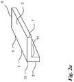
- the L-profile shaped element 1 illustrated in Fig. 1 and 2a was formed from a wood-plastic composite material.
- the wood-plastic composite material was mainly formed from adhesive laminate waste. Polypropylene had been added to the adhesive laminate waste.
- the L-profile shaped element was formed as a monolithic piece by extrusion.
- the L-profile shaped element 1 includes a first 2 and a second 3 leg, wherein the legs are arranged to have different widths 6 but the same thicknesses 7.
- the thickness 7 of the legs 2 and 3 is 28 mm in this embodiment.
- the width of the outer surface b of the leg in the first leg 2 is 68 mm and the width of the inner surface d is 40 mm.
- the width of the outer surface a of the leg in the second leg 3 is 110 mm and the width of the inner surface c is 82 mm.
- the length 5 of the L- profile shaped element 1 may vary depending on the purpose of use of the element.
- An interior angle 14 and an exterior angle 15 are formed between the legs 2 and 3.
- the cavity structure consists of several channel-type cavities 4.
- the cross section of the cavities 4 is otherwise square but at the corners at least partially triangular or trapezoidal. By the cavities, the weight of the L-profile shaped element may be reduced.
- the thickness of the structures between the cavities 4 and of the structures on top of the cavities 4 depends on the purpose of use of the element.
- the thickness of the structures between the cavities 4 and of the structures on top of the cavities 4 is dimensioned in such a way that the structures bear a sufficient load during use of the element and will not sag.
- the thickness of the structures between the cavities 4 and of the structures on top of the cavities 4 is at least 2 mm.
- the diameter of the cavities may be preferably between 3 and 12 mm.
- the thicknesswise ends 7 of the legs 2 and 3, i.e. the lengthwise faces of the L-profile shaped element, are shaped for a joint member.
- a groove-type structure has been provided to the ends 7 as the joint part 13 of the element. This way, the joint member can be easily fitted in connection to the L-profile shaped element, the element can be easily turned around, and the joint member provides a concealed fixing, providing for a finished appearance.
- borders may be provided to the lengthwise 5 edges of the legs of the L-profile shaped element 1, preferably in such a way that in turning the element around it is symmetrical for the part of the borders.
- Any suitable profile may be used as a border.
- the border may be formed by extrusion at the same time in connection with the manufacture of the L-profile shaped element as an integral part of the L-profile shaped element.
- All the top surfaces of the first 2 and the second 3 leg of the L-profile shaped element 1, i.e. the widthwise 6 outer and inner surfaces a, b, c and d, are profiled to be identical by grooving. This provides similar functionality for all surfaces of each leg 2 and 3. This favors the turning around of the element. In particular, a groove-ridge structure 17 improves the frictional properties of the element and thus functions as a frictional area.
- the edges of the element 1 and particularly of the legs 2 and 3 are provided with decorative areas 16a and 16b.
- the outer edges of the legs 2 and 3 on both sides of the legs are provided with smooth, decorative framing areas 16a, all of which are substantially of the same width.
- the interior 14 and exterior 15 angles between the legs are also provided with smooth decorative areas 16b.
- the decorative areas 16a and 16b the element can be better turned around in such a way that the element 1 looks symmetrical on both sides.
- the L-profile shaped element 1 is turnable to the desired position when the element is being used e.g. in a stair structure or in connection with a terrace structure, as seen in Fig. 3 to 6 .
- Fig. 2b illustrates an element equivalent to Fig. 1 and 2a with the exception that the element in Fig. 2b has a first 2 and a second 3 leg, wherein the legs are arranged to have substantially the same widths 6 and the same thicknesses 7.
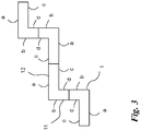
- Fig. 3 illustrates a stair structure formed from the L-profile shaped elements 1 according to Example 1.
- the L-profile shaped elements 1 according to Example 1 are fitted in predetermined positions, in this case alternately both ways around in order to achieve an optimum rise and optimum run for the steps of the stair structure of this embodiment.
- the L-profile shaped element 1 forms together with another L-profile shaped element 1 the rise part 11 of the step and the tread 12.
- Each L-profile shaped element is arranged to be joined from at least one thicknesswise end 7 of the leg to at least one thicknesswise end of the leg of another L-profile shaped element.
- the joints between the elements are provided to the middle of the tread 12 or the rise part 11.
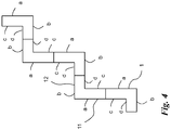
- Fig. 4 illustrates a stair structure formed from the L-profile shaped elements 1 according to Example 1.
- the L-profile shaped elements 1 according to Example 1 are fitted in predetermined positions, in this case alternately both ways around in order to achieve the optimum rise and optimum run for the steps of the stair structure of this embodiment.
- the L-profile shaped element 1 forms together with another L-profile shaped element 1 the rise part 11 of the step and the tread 12.
- Each L-profile shaped element is arranged to be joined from at least one thicknesswise end of the leg to at least one thicknesswise end of the leg of another L-profile shaped element.
- the joints between the elements are provided to the middle of the tread 12 or the rise part 11.
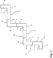
- Fig. 5 illustrates a stair structure formed from the L-profile shaped elements 1 according to Example 1 wherein additional elements 8 have been provided between the L-profile shaped elements 1.
- the additional elements used in this connection are elongated planks 8 formed substantially from the same wood-plastic composite material as the L-profile shaped elements 1.
- the plank 8 is equally thick as the first 2 and the second 3 leg of the L-profile shaped element 1.
- the length of the plank is equal to the length of the L-profile shaped element.
- the width of the plank in this embodiment is 150mm.
- the width of the plank may vary between 50 and 400 mm, more preferably between 100 and 200 mm.
- the thickness of the plank is substantially the same as that of the L-profile shaped element.
- the L-profile shaped elements 1 according to Example 1 are fitted in predetermined positions and joined from at least one thicknesswise end of the leg to at least one thicknesswise end of another element which is either another L-profile shaped element 1 or the additional element 8.
- the L-profile shaped element 1 forms together with another L-profile shaped element 1 the rise part 11 of the step and together with the plank 8 the tread 12.
- the joints between the elements are provided in connection to the tread 12 or the rise part 11, not on the corners.
- Fig. 6 illustrates a terrace structure formed from the L-profile shaped element 1 according to Example 1 and the planks 8 according to Example 4 including the joints between the elements.
- the L-profile shaped element 1 and the planks 8 are joined together by joint members 9. Any suitable joint member may be used as a joint member.
- the joint members according to Fig. 6 have a tongue-type structure matching to the groove-type structures of the L-profile shaped element 1 and the plank 8.
- a base element 10 can be used to support the L-profile shaped element 1 and the entire construction.
- the L-profile shaped element 1 can be secured to the base element 10 by e.g. screws or nails, if desired.
- the L-profile shaped element 1 can be used to cover the edge of a terrace structure formed from planks 8, thus providing to the terrace structure a neat external appearance.
- the L-profile shaped element according to the invention is suitable as different embodiments to be used in the most different applications and structural solutions, preferably in stair structure solutions, alone or together with different additional elements.
Landscapes
- Engineering & Computer Science (AREA)
- Architecture (AREA)
- Civil Engineering (AREA)
- Structural Engineering (AREA)
- Floor Finish (AREA)
- Panels For Use In Building Construction (AREA)
- Extrusion Moulding Of Plastics Or The Like (AREA)
Abstract
Description
- The invention relates to the L-profile shaped element for covering an edge of a terrace structure defined in the preamble of
claim 1, to the use of such defined in the preamble ofclaim 12, and to the method for installing such defined in the preamble of claim 13, and to the terrace structure defined in the preamble ofclaim 14. - Known from the prior art are different floor, ceiling and wall elements formed from a composite material for both interior and exterior use. Composite materials have lately become more general in the manufacture of different surface elements by virtue of their easy maintenance, tailored weather-resistance and new color palette.
- Furthermore, it is known to use different edge strips in connection with floor or terrace structures formed from a composite material to finish the visual look. However, a problem in the use of the known edge strips is that they are easily loosened and seldom withstand intensive wear and use.
- In addition, known from the prior art are different stair structures. Stairs have mainly been built from wood, concrete or metal. Known from publication
US4951434 is a stair structure formed from plastic or carbon fiber, wherein the structure includes more than one step. The structure is formed by injection molding. -
DE202009013314U1 andUS2006242916A1 disclose a corner profile for a terrace structure. - An objective of the invention is to disclose a new type of an L-profile shaped element suitable for many purposes of use. Furthermore, an objective of the invention is to disclose a new manner of forming stair structures and terrace structures. In addition, an objective of the invention is to disclose a method for installing L-profile shaped elements to each other, e.g. in order to form stair structures.
- The L-profile shaped element, the uses thereof and the installation methods therefor according to the invention are characterized by what is presented in the claims.
- The invention is based on an L-profile shaped element. According to the invention the L-profile shaped element is formed as a monolithic piece, and the L-profile shaped element includes a first and a second leg, wherein the legs are arranged to have substantially the same thicknesses, at least one edge of each leg is provided with joint parts functioning in substantially the same manner, and the element is turnable to a desired position.
- An L-profile shaped element means in this context a profile of any length having an L-shaped cross section. The dimensions of the L-profile shaped element, such as the length as well as the width and thickness of the legs, may vary depending on the application. Preferably, the thicknesses of the legs as well as the widths of the inner and outer surfaces are predetermined and depend on the purpose of use of the L-profile shaped elements. In this invention the L-profile shaped element is preferably used as an angular element in order to form an angular structure. The L-profile shaped element preferably includes an interior angle and an exterior angle.
- Preferably, joint parts functioning in the same manner are to be fitted to the edges of the legs, i.e. to the edges in the thickness direction, of the L-profile shaped element. In a preferred embodiment a joint part is to function in the same manner in the interior as well as exterior of the L-profile shaped element, regardless which way around the element has been turned. In this connection the joint part may be shaped for a joint member, or it may function as one directly. Preferably, the joint parts of the legs must be equally thick or disposed at the same height in the thickness direction of the leg, so that the legs of the elements to be joined are set flush with each other when joined together. Preferably, there is less than 2mm, more preferably less than 1 mm, of deviation in the thickness or mounting height of the joint parts. The joint part may be selected according to the purpose of use. E.g. a groove or tongue structure or other suitable structure may be used as a joint part.
- In one embodiment the thickness of the leg of the L-profile shaped element is between 3 and 100 mm, preferably between 20 and 35 mm and more preferably between 25 and 30 mm. Preferably, the difference in the thickness between the legs is less than 2mm, more preferably less than 1 mm.
- In one embodiment the width of the external dimension of at least one leg of the L-profile shaped element is between 30 and 280 mm, preferably between 40 and 250 mm and more preferably between 50 and 120 mm, and the width of the dimension of the inner sur- face is between 27 and 397 mm, preferably between 28 and 288 mm and in one preferred embodiment between 55 and 125 mm. In one embodiment the width of the external dimension of at least one leg of the L-profile shaped element is between 30 and 400 mm, preferably between 40 and 300 mm and more preferably between 80 and 150 mm, and the width of the dimension of the inner surface is between 27 and 397 mm, preferably between 28 and 288 mm and more preferably between 55 and 125 mm.
- In one embodiment of the invention the L-profile shaped element includes a first and a second leg, wherein the legs are arranged to have substantially different widths but substantially the same thicknesses. In one embodiment the width of the second leg is 1 to 13.3 times, preferably 1.1 to 7.5 times, more preferably 1.2 to 3 times and most preferably 1.5 to 1.7 times the width of the first leg.
- In one embodiment the L-profile shaped element includes a first and a second leg, wherein the legs are arranged to have substantially the same widths and substantially the same thicknesses. In this case the difference in the width of the legs is less than 2 mm, more preferably less than 1 mm.
- In one embodiment of the invention the L-profile shaped element is arranged to be joined from the thicknesswise end of at least one leg, which, at the same time, is the lengthwise face of the L-profile shaped element, by a joint part to at least one other element which may be e.g. another L-profile shaped element or an additional element to be connected to an L- profile shaped element, or another element. In one embodiment the joint part of the thicknesswise end of the leg is shaped for a joint member in order to facilitate the joining e.g. with another L-profile shaped element or another element.
- In one embodiment of the invention a monolithic interior angle is formed without joints between the inner surfaces of the legs. In one embodiment a monolithic exterior angle is formed without joints between the outer surfaces of the legs. This way, the surface is continuous for the part of the entire angular structure which is seamless and safe. In this manner a jointless angular element is provided.
- In one embodiment of the invention the patterning of the legs of the L-profile shaped element is arranged to be at least partially the same, which facilitates turning of the element. Preferably, also the patterning of both sides of the leg is arranged to be at least partially the same. Similar surfaces provide a harmonious look, regardless in which manner and which way around the element is installed. In one embodiment at least part of the surface of the leg is modified, e.g. by grooving. In one embodiment the top surface of the leg is at least partially smooth. In one embodiment the groove patterning or smooth surface provided to the legs is the same, but the area covered by the patterning may vary. The thicknesswise end surfaces of the legs need not be similar to the other side surfaces of the legs.
- In one embodiment of the invention the same surface patterning is provided on both sides of the exterior angle between the legs. In one embodiment of the invention the same surface patterning is provided on both sides of the interior angle between the legs. In one embodiment of the invention the same surface patterning is provided on both sides of the exterior angle and the interior angle between the legs. The surface patterning may vary according to the purpose of use, but preferably all surfaces of all legs have a functionally similar patterning. In one embodiment the leg is provided with a groove-ridge patterning. In one embodiment the leg is provided with a substantially smooth framing area which may serve as a decorative area or border at the edge of the leg. In one embodiment the leg is provided with a groove ridge patterning to provide the desired functionality to the surface of the leg and a substantially smooth border area and/or angular area to provide a decorative appearance to the surface of the leg. Preferably, the surface patterning is provided to the surface of the leg without any such rises or elevations on which one may stumble or which may affect the safety e.g. in stair structures.
- In one embodiment of the invention at least one cavity structure is provided within at least one leg. The cavity structure may consist of one or several cavities, and the cavity may be a channel, opening or other cavity structure. If desired, the cavities may be filled with a suitable material, such as light, elastic, insulating or otherwise suitable material. In one embodiment the cavity is arranged to be elongated in the lengthwise direction of the leg. The cavities provide for control of the weight of the L-profile shaped element. The number or ratio of the cavities relative to the rest of the structure depends on the starting material used and the strength and/or load-carrying capacity desired for the element.
- In one embodiment of the invention a border isprovided to at least one lengthwise edge of at least one leg. The lengthwise edge may be the lengthwise outer edge of the leg or the lengthwise inner edge of the leg, i.e. the lengthwise edge forming an angle with another leg. In this case, in one stair embodiment, the up- and/or forward-projecting edge of the rise and the tread of a step to be formed from the elements can be bordered or covered. The width of the border may vary according to the purpose of use. In one preferred embodiment the border is formed in connection with the manufacture of the L-profile shaped element, e.g. by extrusion or an additional extrusion step or alternatively by modifying or patterning the material of the element in a desired area. In one preferred embodiment the border is provided to the L-profile shaped element symmetrically in such a manner that the element looks the same from different sides, when turned to a desired position.
- In one embodiment of the invention a border is provided to at least one edge in the width direction of at least one leg. In one embodiment a profile of a desired shape is used as the border. The border may be formed from the same material or from a different material. The border may be an integral part of the element according to the invention, or it may be separate and joined to the element. The border may serve as a decorative part. In one embodiment the border may be formed in connection with the manufacture of the L-profile shaped element. In one embodiment the border can be joined to the L-profile shaped element after the manufacture of the element or in connection with the installation of the element.
- In one embodiment the L-profile shaped element is formed by a forming method based on heat and pressure.
- In one preferred embodiment the element is formed as a monolithic piece by extrusion.
- In one embodiment the L-profile shaped element is formed from a starting material which contains fiber-based and plastic-based components.
- In one embodiment the L-profile shaped element is formed from a composite material which contains fiber-based components and/or plastic-based components and is used as the starting material. The composite material is formed from one or several raw stocks or raw stock materials. The raw stock or raw stock material may contain any fiber-based, e.g. plant fiber-based, such as wood fiber, straw, reed or flax-based, or other fiber-based components and/or plastic-based components. The composite material may be in a shredded, granulate, agglomerate, crushed or equivalent form.
- In one embodiment the composite material is a wood-plastic composite material. Preferably, the wood-plastic composite material is formed from raw stocks which contain mainly fiber-based, e.g. paper-based, material, and plastic-based material, such as thermo- setting or thermoplastic resin.
- In this context a paper-based material means any paper-based material which is preferably mainly formed from plant fibers. The paper-based material may be formed from chemical pulp fibers from which lignin has been removed and/or from fibers which contain lignin. In a preferred embodiment the paper-based material contains plant fibers in an amount of more than 50 w-% of the material.
- In one embodiment the parts of the fiber-based components may vary between 0 and 80 % and the parts of the plastic-based components may vary between 0 and 100 % in the composite material.
- In one embodiment the composite material contains glue matter preferably originating from the raw stock of the composite material.
- In one embodiment the raw stock or raw stocks contain siliconized material, e.g. siliconized film or paper material. The siliconized material may be silicone-based or silicone compound-based material or silicone-containing compound that may be part of an other material or provided to the surface of another material, such as plastic-based and/or fiber-based material.
- In one embodiment the L-profile shaped element is formed at least partially from recycled material. In one embodiment the L-profile shaped element is formed mainly from recycled material.
- In one embodiment the L-profile shaped element is formed at least partially from adhesive laminate waste, in one preferred embodiment mainly, in an amount of more than 50 w-%, from adhesive laminate waste. In one embodiment the L-profile shaped element contains at least one adhesive laminate waste component. In one embodiment the L-profile shaped element contains more than one adhesive laminate waste component.
- In one embodiment the adhesive laminate waste contains adhesive material on which a layer of glue matter has been provided, and fitted on the layer of glue matter as a protective sheet for the layer of glue is release material that can be easily released at the application site of the adhesive item. In one preferred embodiment the adhesive material and/or the release material contains a wood fiber -based component and/or plastic- or polymer-based or other organic component. Also, the use of different inorganic materials is possible. In one embodiment the adhesive and/or release material is wood fiber-based paper, paperboard or the like. In one embodiment the wood fiber-based paper, paperboard or the like contains or is treated with plastic- or polymer-based material. In one embodiment the adhesive and/or release material may substantially be formed from plastic- or polymer-based material. In one embodiment the release material is mainly formed from plastic-based material, containing e.g. polypropylene, polyethylene, polyethylene terephthalate or their mixtures. In one embodiment the release material contains siliconized material, e.g. siliconized film or fiber-based material. In one embodiment the release material is coated with silicone-based material or compound.
- In one embodiment finished adhesive laminate products, waste material produced by them and/or in their manufacture may be used as adhesive laminate waste in the manufacture of the composite material. In addition, reject material from production and recycling material from the upgrading step or end use applications of adhesive laminate products may be used. In one embodiment the adhesive laminate waste comes from adhesive laminate production which mainly produces production reject waste, edge trimming waste cut off from rolls, and roll ends, from the adhesive laminate printing plant which mainly produces roll ends and adhesive material left over from die-cutting of stickers and labels, and reject waste, and/or from the adhesive laminate end user customer who pastes the printed stickers and labels or the like on products. The waste from the end user is mainly release material, roll ends and waste from the finished product.
- In one embodiment the adhesive laminate waste may contain a variable number of different adhesive laminate waste components, such as adhesive material, glue matter and release material. The glue matter may preferably be in connection with adhesive material and/or release material. In one embodiment the adhesive laminate waste contains 0 to 70 % of adhesive material, 0 to 100 % of release material and 0 to 40 % of glue matter.
- In one embodiment the starting material, e.g. the composite material, may contain, in addition to plastic-based and/or fiber-based components, different additives and/or additional plastic to improve the mechanical properties, outdoor durability or processability of the product.
- In one embodiment at least one additive is added to the starting material, e.g. the composite material, in connection with the manufacture of the composite material or in connection with the manufacture of the L-profile shaped element. E.g. a coloring agent, lubricant, fire retardant, adhesion promoter, anti-mildew compound, antioxidant and uv-stabilizer may be used as additives. Fibrous materials, organic fillers, inorganic fillers, powdery reinforcements, powdery additives, talc, wood fibers, chemical pulp fibers, paper and their combinations may preferably be added to the composite material as the additive.
- In one embodiment additional plastic is added to the starting material, e.g. the composite material, in connection with the manufacture of the composite material or in connection with the manufacture of the L-profile shaped element. Virgin plastic and/or recycling plastic may be used as additional plastic. The L-profile shaped element may be manufactured without additional plastic or with additional plastic. In one embodiment e.g. polyolefin, polypropylene, polyethylene (HDPE, LDPE) or other suitable plastic or a mixture thereof is added to the adhesive laminate waste material as additional plastic to manufacture the wood composite material.
- Preferably, the L-profile shaped element is formed by extrusion. In one embodiment the L-profile shaped element is cooled after compressing to shape in connection with or after the extrusion. The extrusion may be performed by any manner and apparatus known per se.
- In one embodiment of the invention the L-profile shaped element is used in connection with a stair structure in order to form a step, such that the L-profile shaped element forms the angular part of the step and at least partially the rise part of the step as well as the tread in such a manner that the angular part of the step is always one and the same piece. Preferably, one leg of the L-profile shaped element forms partially or entirely the rise part and the other leg forms the tread. In one embodiment the L-profile shaped element is used together with another L-profile shaped element in order to form a step in connection with a stair structure, such that the L-profile shaped elements form together both the rise part of the step as well as the tread. In one embodiment the L-profile shaped element forms both the rise part of the step as well as the tread.
- In one embodiment of the invention the L-profile shaped element is used in connection with a terrace structure, e.g. as an edge strip or edge step.
- In addition, the invention relates to a method for installing the L-profile shaped elements. According to the invention at least two L-profile shaped elements according to any of the descriptions presented above are fitted and joined in a position relative to each other as required by the purpose of use by means of joint parts provided to the edges of the legs, wherein all joint parts function substantially in the same manner. The joints between the elements are provided in stair embodiments in the rise or the step part of the stair, not at the corners.
- In one embodiment of the invention at least one additional element is fitted and joined between the L-profile shaped elements.
- An additional element in this context means an elongated element, such as a plank-like, board-like or correspondingly shaped element, or a slab-like element or an element having another shape. The additional element may be two- or three-dimensional. The plank-like element may be formed e.g. as a rectangle, elongated parallelogram, square or the like. The additional element may be of any size depending on the purpose of use. Preferably, the dimensions of the additional element are such that it is compatible with the L-profile shaped element according to the invention. In one preferred element the thickness of the additional element is substantially the same as the thickness of the legs of the L-profile shaped element. In one embodiment the additional element is substantially equally long as the L-profile shaped element.
- In on embodiment the additional element is formed from any of the composite materials presented above. Alternatively, the additional element is formed from another material suitable for the purpose of use.
- In one embodiment of the invention the L-profile shaped element according to any of the descriptions presented above is fitted and joined from the thicknesswise end of at least one leg to at least one other L-profile shaped element and/or to at least one additional element.
- In one embodiment of the invention the L-profile shaped element is fitted as the interior angle of an angular structure in connection with a stair structure.
- In one embodiment of the invention the L-profile shaped element is fitted as the exterior angle of an angular structure.
- In addition, the invention relates to a method for installing the L-profile shaped element. According to the invention at least one L-profile shaped element according to any of the descriptions presented above is fitted and joined in connection to a terrace structure in a position required by the purpose of use. By joining the L-profile shaped element to the edge of a terrace the edge becomes neat, and the L-profile shaped element covers the structures under the terrace elements, such as support structures, rails or equivalent structures.
- In one embodiment of the invention the L-profile shaped element is fitted as the interior angle of an angular structure in connection with terrace structures. In one embodiment of the invention the L- profile shaped element is fitted as the exterior angle of an angular structure.
- In one embodiment the L-profile shaped elements can be joined to each other, and the L-profile shaped element and an additional element or other element can be joined together by different joint members, e.g. T-joint members or joint profiles. A joint member in this context means a joint and/or mounting member. Any joint member or joint profile known per se and suitable for the purpose can be used as the joint member. The joint profile may be e.g. the joint profile disclosed in applications
PCT/FI2010/051100 PCT/FI2010/050703 - In one embodiment the L-profile shaped element is mountable, e.g. to a base, by nailing or screwing or in an equivalent manner. In one embodiment the L-profile shaped element is provided with a site or location e.g. to facilitate the possible nailing-through or screwing-through.
- In one embodiment the surface of the L-profile shaped element and/or additional element is provided coarse or grooved to provide friction. In one embodiment the surface of the L-profile shaped element and/or additional element is provided substantially smooth. The L-profile shaped element or the surface thereof may be shaped so as to also function as a decorative part.
- The L-profile shaped element according to the invention may be used in connection with stair structures or terrace structures in both interior and exterior applications. In addition, the L-profile shaped element according to the invention can be used in forming e.g. benches, flower boxes or equivalent structures. The L-profile shaped element according to the invention can be used in assembled and disassembled structures or in fixed structures.
- By the L-profile shaped element according to the invention, a desired type of a stair structure or terrace structure can be formed either by using the L-profile shaped elements alone or together with different additional elements. By using different colors on the additional elements and/or L-profile shaped elements, different patterns can be created on the surface.
- By the invention, an ecological element that withstands intensive wear is provided for different purposes of use. An advantage of the L-profile shaped element according to the invention is that it is turnable around freely, and thereby e.g. different rise heights and runs can be provided for stair structures.
- The L-profile shaped element can be manufactured easily and quickly in a single manufacturing step, e.g. extrusion step. One and the same extrusion apparatus can be used to manufacture an extensive range of unlike L-profile shaped elements.
-
- Fig. 1
- illustrates one L-profile shaped element according to the invention as a cross-sectional view,
- Fig. 2a
- illustrates one L-profile shaped element according to the invention,
- Fig. 2b
- illustrates another L-profile shaped element according to the invention,
- Fig. 3
- illustrates one structure according to the invention formed from the L-profile shaped elements as a cross-sectional view,
- Fig. 4
- illustrates a second structure according to the invention formed from the L-profile shaped elements as a cross-sectional view,
- Fig. 5
- illustrates a third structure according to the invention formed from the L-profile shaped elements as a cross-sectional view with additional elements provided between the L-profile shaped elements, and
- Fig. 6
- illustrates one structure according to the invention formed from the L-profile shaped elements including the joints.
- In the following, the invention will be described by detailed examples of its embodiments with reference to the accompanying, illustrative figures wherein the L-profile shaped elements and additional elements are not depicted fully on scale.
- The L-profile shaped
element 1 illustrated inFig. 1 and2a was formed from a wood-plastic composite material. The wood-plastic composite material was mainly formed from adhesive laminate waste. Polypropylene had been added to the adhesive laminate waste. The L-profile shaped element was formed as a monolithic piece by extrusion. - The L-profile shaped
element 1 according toFig. 1 and2a includes a first 2 and a second 3 leg, wherein the legs are arranged to havedifferent widths 6 but thesame thicknesses 7. Thethickness 7 of thelegs first leg 2 is 68 mm and the width of the inner surface d is 40 mm. The width of the outer surface a of the leg in thesecond leg 3 is 110 mm and the width of the inner surface c is 82 mm. The length 5 of the L- profile shapedelement 1 may vary depending on the purpose of use of the element. - An
interior angle 14 and anexterior angle 15 are formed between thelegs - Within the
legs elongated cavity structures 4 fitted in the lengthwise direction 5 of the legs and, at the same time, in the lengthwise direction of the L-profile shaped element. The cavity structure consists of several channel-type cavities 4. The cross section of thecavities 4 is otherwise square but at the corners at least partially triangular or trapezoidal. By the cavities, the weight of the L-profile shaped element may be reduced. The thickness of the structures between thecavities 4 and of the structures on top of thecavities 4 depends on the purpose of use of the element. The thickness of the structures between thecavities 4 and of the structures on top of thecavities 4 is dimensioned in such a way that the structures bear a sufficient load during use of the element and will not sag. In this embodiment the thickness of the structures between thecavities 4 and of the structures on top of thecavities 4 is at least 2 mm. The diameter of the cavities may be preferably between 3 and 12 mm. - The thicknesswise ends 7 of the
legs ends 7 as the joint part 13 of the element. This way, the joint member can be easily fitted in connection to the L-profile shaped element, the element can be easily turned around, and the joint member provides a concealed fixing, providing for a finished appearance. - If desired, borders may be provided to the lengthwise 5 edges of the legs of the L-profile shaped
element 1, preferably in such a way that in turning the element around it is symmetrical for the part of the borders. Any suitable profile may be used as a border. Alternatively, the border may be formed by extrusion at the same time in connection with the manufacture of the L-profile shaped element as an integral part of the L-profile shaped element. - All the top surfaces of the first 2 and the second 3 leg of the L-profile shaped
element 1, i.e. the widthwise 6 outer and inner surfaces a, b, c and d, are profiled to be identical by grooving. This provides similar functionality for all surfaces of eachleg ridge structure 17 improves the frictional properties of the element and thus functions as a frictional area. The edges of theelement 1 and particularly of thelegs decorative areas legs decorative framing areas 16a, all of which are substantially of the same width. The interior 14 andexterior 15 angles between the legs are also provided with smoothdecorative areas 16b. By means of thedecorative areas element 1 looks symmetrical on both sides. The L-profile shapedelement 1 is turnable to the desired position when the element is being used e.g. in a stair structure or in connection with a terrace structure, as seen inFig. 3 to 6 . -
Fig. 2b illustrates an element equivalent toFig. 1 and2a with the exception that the element inFig. 2b has a first 2 and a second 3 leg, wherein the legs are arranged to have substantially thesame widths 6 and thesame thicknesses 7. -
Fig. 3 illustrates a stair structure formed from the L-profile shapedelements 1 according to Example 1. - The L-profile shaped
elements 1 according to Example 1 are fitted in predetermined positions, in this case alternately both ways around in order to achieve an optimum rise and optimum run for the steps of the stair structure of this embodiment. The L-profile shapedelement 1 forms together with another L-profile shapedelement 1 therise part 11 of the step and thetread 12. - Each L-profile shaped element is arranged to be joined from at least one
thicknesswise end 7 of the leg to at least one thicknesswise end of the leg of another L-profile shaped element. - The joints between the elements are provided to the middle of the
tread 12 or therise part 11. -
Fig. 4 illustrates a stair structure formed from the L-profile shapedelements 1 according to Example 1. - The L-profile shaped
elements 1 according to Example 1 are fitted in predetermined positions, in this case alternately both ways around in order to achieve the optimum rise and optimum run for the steps of the stair structure of this embodiment. The L-profile shapedelement 1 forms together with another L-profile shapedelement 1 therise part 11 of the step and thetread 12. - Each L-profile shaped element is arranged to be joined from at least one thicknesswise end of the leg to at least one thicknesswise end of the leg of another L-profile shaped element.
- The joints between the elements are provided to the middle of the
tread 12 or therise part 11. -
Fig. 5 illustrates a stair structure formed from the L-profile shapedelements 1 according to Example 1 whereinadditional elements 8 have been provided between the L-profile shapedelements 1. - The additional elements used in this connection are
elongated planks 8 formed substantially from the same wood-plastic composite material as the L-profile shapedelements 1. - The
plank 8 is equally thick as the first 2 and the second 3 leg of the L-profile shapedelement 1. The length of the plank is equal to the length of the L-profile shaped element. The width of the plank in this embodiment is 150mm. The width of the plank may vary between 50 and 400 mm, more preferably between 100 and 200 mm. Preferably, the thickness of the plank is substantially the same as that of the L-profile shaped element. - The L-profile shaped
elements 1 according to Example 1 are fitted in predetermined positions and joined from at least one thicknesswise end of the leg to at least one thicknesswise end of another element which is either another L-profile shapedelement 1 or theadditional element 8. The L-profile shapedelement 1 forms together with another L-profile shapedelement 1 therise part 11 of the step and together with theplank 8 thetread 12. The joints between the elements are provided in connection to thetread 12 or therise part 11, not on the corners. -
Fig. 6 illustrates a terrace structure formed from the L-profile shapedelement 1 according to Example 1 and theplanks 8 according to Example 4 including the joints between the elements. - The L-profile shaped
element 1 and theplanks 8 are joined together byjoint members 9. Any suitable joint member may be used as a joint member. The joint members according toFig. 6 have a tongue-type structure matching to the groove-type structures of the L-profile shapedelement 1 and theplank 8. In the structure according toFig. 6 abase element 10 can be used to support the L-profile shapedelement 1 and the entire construction. In addition, the L-profile shapedelement 1 can be secured to thebase element 10 by e.g. screws or nails, if desired. - The L-profile shaped
element 1 can be used to cover the edge of a terrace structure formed fromplanks 8, thus providing to the terrace structure a neat external appearance. - The L-profile shaped element according to the invention is suitable as different embodiments to be used in the most different applications and structural solutions, preferably in stair structure solutions, alone or together with different additional elements.
- The invention is not limited merely to the examples referred to above; instead, many variations are possible within the scope of the inventive idea defined by the claims.
Claims (14)
- An L-profile shaped element for covering an edge of a terrace structure wherein- the L-profile shaped element (1) being formed as a monolithic piece,- the L-profile shaped element (1) being formed from a composite material, which contains fiber-based components and/or plastic-based components and which is used as a starting material,- the L-profile shaped element (1) includes a first leg (2) and a second leg (3), wherein dimensions of the L-profile shaped element (1) being length, width and thickness of the first leg (2) and the second leg (3),- the first leg (2) and the second leg (3) being arranged to have substantially the same thicknesses,characterized in that- joint parts (13) are fitted to the edges in the thickness direction of the first leg (2) and of the second leg (3),- the joint parts (13) being to function in the same manner in the interior as well as exterior of the L-profile shaped element, regardless which way around the element has been turned,- the joint parts (13) being selected from a groove or tongue structure,- the L-profile shaped element (1) being arranged to be joined from the thicknesswise end (7) of at least one of the first leg (2) and the second leg (3), which is at the same time the lengthwise face of the L-profile shaped element (1), to at least one plank-like additional element of substantially the same thickness, which is adapted to be connected to said L-profile shaped element by means of the joint parts (13).
- The L-profile shaped element for covering an edge of a terrace structure according to claim 1, characterized in that a monolithic interior angle (14) is formed without joints between the inner surfaces of the first leg (2) and the second leg (3).
- The L-profile shaped element for covering an edge of a terrace structure according to any one of claims 1 to 2, characterized in that a monolithic exterior angle (15) is formed without joints between the outer surfaces of the first leg (2) and the second leg (3).
- The L-profile shaped element for covering an edge of a terrace structure according to any one of claims 1 to 3, characterized in that an identical surface pattern is provided on both sides of the interior angle (14) between the first leg (2) and the second leg (3).
- The L-profile shaped element for covering an edge of a terrace structure according to any one of claims 1 to 4, characterized in that an identical surface pattern is provided on both sides of the exterior angle (15) between the first leg (2) and the second leg (3).
- The L-profile shaped element for covering an edge of a terrace structure according to any one of claims 1 to 5, characterized in that the surfaces of the first leg (2) and of the second leg (3) are provided with a surface patterning (17) to provide functionality.
- The L-profile shaped element for covering an edge of a terrace structure according to any one of claims 1 to 6, characterized in that at least one cavity structure (4) is provided within at least one of the first leg (2) and the second leg (3).
- The L-profile shaped element for covering an edge of a terrace structure according to any one of claims 1 to 7, characterized in that at least one lengthwise edge (5) of at least one of the first leg (2) and the second leg (3) is provided with a border.
- The L-profile shaped element for covering an edge of a terrace structure according to any one of claims 1 to 8, characterized in that the L-profile shaped element (1) is formed as a monolithic piece by extrusion.
- The L-profile shaped element for covering an edge of a terrace structure according to any one of claims 1 to 9, characterized in that the L-profile shaped element (1) is formed from the starting material to which an additive and/or a plastic has been added.
- The L-profile shaped element for covering an edge of a terrace structure according to any one of claims 1 to 10, characterized in that the plank-like additional element comprises a plank-like element, a board-like element, a slab-like element, a form of a rectangle, a form of an elongated parallelogram or a form of a square.
- Use of the L-profile shaped element, according to any of the claims 1-11 for covering an edge of a terrace structure.
- A method for installing the L-profile shaped element for covering an edge of a terrace structure according to any of the claims 1-11, characterized in that the method comprises fitting and joining the L-profile shaped element (1) from the thicknesswise end (7) of at least one of the first and the second leg (2, 3), which is at the same time the lengthwise face of the L-profile shaped element, to at least one plank-like additional element of substantially the same thickness by means of the joint part (13), in connection to a terrace structure.
- A terrace structure comprising an L-profile shaped element for covering an edge of a terrace structure according to any of the claims 1-11.
Applications Claiming Priority (3)
| Application Number | Priority Date | Filing Date | Title |
|---|---|---|---|
| FI20105610A FI125904B (en) | 2010-05-31 | 2010-05-31 | L-profile shaped element, its use and method of mounting it |
| PCT/FI2011/050507 WO2011151520A1 (en) | 2010-05-31 | 2011-05-31 | L-profile shaped element, the use of same and a method for installing same |
| EP11789312.3A EP2585647B1 (en) | 2010-05-31 | 2011-05-31 | Stair structure comprising l-profile shaped elements and method for installing same |
Related Parent Applications (2)
| Application Number | Title | Priority Date | Filing Date |
|---|---|---|---|
| EP11789312.3A Division EP2585647B1 (en) | 2010-05-31 | 2011-05-31 | Stair structure comprising l-profile shaped elements and method for installing same |
| EP11789312.3A Division-Into EP2585647B1 (en) | 2010-05-31 | 2011-05-31 | Stair structure comprising l-profile shaped elements and method for installing same |
Publications (2)
| Publication Number | Publication Date |
|---|---|
| EP3179006A1 true EP3179006A1 (en) | 2017-06-14 |
| EP3179006B1 EP3179006B1 (en) | 2019-04-17 |
Family
ID=42234385
Family Applications (2)
| Application Number | Title | Priority Date | Filing Date |
|---|---|---|---|
| EP17152773.2A Active EP3179006B1 (en) | 2010-05-31 | 2011-05-31 | L-profile shaped element, the use of same and a method for installing same |
| EP11789312.3A Active EP2585647B1 (en) | 2010-05-31 | 2011-05-31 | Stair structure comprising l-profile shaped elements and method for installing same |
Family Applications After (1)
| Application Number | Title | Priority Date | Filing Date |
|---|---|---|---|
| EP11789312.3A Active EP2585647B1 (en) | 2010-05-31 | 2011-05-31 | Stair structure comprising l-profile shaped elements and method for installing same |
Country Status (8)
| Country | Link |
|---|---|
| US (1) | US20130074429A1 (en) |
| EP (2) | EP3179006B1 (en) |
| JP (1) | JP5887342B2 (en) |
| CN (1) | CN203188510U (en) |
| DE (2) | DE212011100104U1 (en) |
| DK (1) | DK2585647T3 (en) |
| FI (1) | FI125904B (en) |
| WO (1) | WO2011151520A1 (en) |
Families Citing this family (5)
| Publication number | Priority date | Publication date | Assignee | Title |
|---|---|---|---|---|
| US8621802B2 (en) * | 2009-06-03 | 2014-01-07 | Alexis Spyrou | Brick bracket for installation of a ledger on the brick facing or veneer of a structure and associated methods for the installation of the brick bracket on the brick facing |
| CN107630532A (en) * | 2017-09-25 | 2018-01-26 | 苏州柯利达装饰股份有限公司 | A kind of edge closing bar at step negative and positive angle |
| US11718998B2 (en) | 2021-08-18 | 2023-08-08 | Miro Industries, Inc. | Stair stringer |
| USD990711S1 (en) | 2021-08-18 | 2023-06-27 | Miro Industries, Inc. | Stair stringer |
| ES1294925Y (en) * | 2022-06-15 | 2023-01-03 | Calvo Antonio Puertas | PREFABRICATED PIECE FOR THE CONSTRUCTION OF STAIRS AND BENCHES |
Citations (7)
| Publication number | Priority date | Publication date | Assignee | Title |
|---|---|---|---|---|
| DE2921457A1 (en) * | 1979-05-26 | 1980-11-27 | Bohn Geb Koehnlein Irmgard | Composite cantilevered staircase metal step sections - are filler profiles arranged across width, with ends welded to corner profiles |
| US4951434A (en) | 1989-03-07 | 1990-08-28 | Schmidt George A | Pre-formed stair construction |
| DE9214772U1 (en) * | 1992-10-30 | 1993-03-25 | Bergmann, Gunther, 5908 Neunkirchen | Staircase renovation element |
| BE1008493A4 (en) * | 1994-06-24 | 1996-05-07 | Vanhee Arnold | Steps |
| US20060242916A1 (en) | 2005-05-02 | 2006-11-02 | Carney Timber Company | Edge boards and related assemblies |
| WO2008046955A1 (en) * | 2006-10-19 | 2008-04-24 | Upm-Kymmene Oyj | Wood composite material and method for making same |
| DE202009013314U1 (en) | 2009-10-06 | 2010-02-11 | Bremer Holzwerke Gmbh | Decking system |
Family Cites Families (16)
| Publication number | Priority date | Publication date | Assignee | Title |
|---|---|---|---|---|
| US1166428A (en) * | 1915-01-12 | 1916-01-04 | George W Brooks | Pressed-steel stair. |
| US2288470A (en) * | 1940-11-15 | 1942-06-30 | O W Jackson & Co Inc | Protective stair edging |
| DE1955443A1 (en) * | 1969-09-29 | 1971-05-06 | Flohr Friedrich Wilhelm Herman | Flohr patent stairs |
| US3978628A (en) * | 1973-02-20 | 1976-09-07 | Jack Turner | Constructional units for stepped structures |
| JPS5768851U (en) * | 1980-10-15 | 1982-04-24 | ||
| JPH01177326U (en) * | 1988-06-03 | 1989-12-19 | ||
| JPH0577403U (en) * | 1992-03-18 | 1993-10-22 | 孝一 端場 | Building blocks |
| US5918962A (en) * | 1993-06-16 | 1999-07-06 | Tivoli Industries, Inc. | Dual step light and aisle indicator apparatus |
| JP2001032482A (en) * | 1999-07-21 | 2001-02-06 | Masao Suzuki | Structure of stairs for building |
| US6554446B1 (en) * | 2000-01-03 | 2003-04-29 | Targetti-Tivoli Inc. | Step illumination apparatus |
| JP3924313B2 (en) * | 2001-12-14 | 2007-06-06 | 株式会社 阪急ファシリティーズ | Stair repair material and stair repair method using the same |
| JP3971209B2 (en) * | 2002-03-07 | 2007-09-05 | 岐阜プラスチック工業株式会社 | Stair structure and stairs comprising the stair structure |
| US6895717B1 (en) * | 2003-06-03 | 2005-05-24 | J.D. Grinstead General Construction Company, Inc. | Component and method for restoring a stairway |
| DE102009010461A1 (en) | 2009-02-13 | 2010-08-19 | Alfred Kärcher Gmbh & Co. Kg | Motor pump unit |
| DE202010018156U1 (en) | 2009-09-14 | 2014-06-02 | Upm-Kymmene Corporation | support profile |
| FI20096413A7 (en) | 2009-12-31 | 2011-07-01 | Upm Kymmene Corp | Connection profile and method for connecting elements |
-
2010
- 2010-05-31 FI FI20105610A patent/FI125904B/en active IP Right Grant
-
2011
- 2011-05-31 CN CN2011900005467U patent/CN203188510U/en not_active Expired - Lifetime
- 2011-05-31 JP JP2013512954A patent/JP5887342B2/en not_active Expired - Fee Related
- 2011-05-31 EP EP17152773.2A patent/EP3179006B1/en active Active
- 2011-05-31 DK DK11789312.3T patent/DK2585647T3/en active
- 2011-05-31 EP EP11789312.3A patent/EP2585647B1/en active Active
- 2011-05-31 US US13/701,351 patent/US20130074429A1/en not_active Abandoned
- 2011-05-31 WO PCT/FI2011/050507 patent/WO2011151520A1/en not_active Ceased
- 2011-05-31 DE DE212011100104U patent/DE212011100104U1/en not_active Expired - Lifetime
- 2011-05-31 DE DE202011110316U patent/DE202011110316U1/en not_active Expired - Lifetime
Patent Citations (7)
| Publication number | Priority date | Publication date | Assignee | Title |
|---|---|---|---|---|
| DE2921457A1 (en) * | 1979-05-26 | 1980-11-27 | Bohn Geb Koehnlein Irmgard | Composite cantilevered staircase metal step sections - are filler profiles arranged across width, with ends welded to corner profiles |
| US4951434A (en) | 1989-03-07 | 1990-08-28 | Schmidt George A | Pre-formed stair construction |
| DE9214772U1 (en) * | 1992-10-30 | 1993-03-25 | Bergmann, Gunther, 5908 Neunkirchen | Staircase renovation element |
| BE1008493A4 (en) * | 1994-06-24 | 1996-05-07 | Vanhee Arnold | Steps |
| US20060242916A1 (en) | 2005-05-02 | 2006-11-02 | Carney Timber Company | Edge boards and related assemblies |
| WO2008046955A1 (en) * | 2006-10-19 | 2008-04-24 | Upm-Kymmene Oyj | Wood composite material and method for making same |
| DE202009013314U1 (en) | 2009-10-06 | 2010-02-11 | Bremer Holzwerke Gmbh | Decking system |
Also Published As
| Publication number | Publication date |
|---|---|
| DE202011110316U1 (en) | 2013-06-11 |
| EP2585647A1 (en) | 2013-05-01 |
| FI20105610A0 (en) | 2010-05-31 |
| EP2585647B1 (en) | 2017-12-20 |
| CN203188510U (en) | 2013-09-11 |
| EP3179006B1 (en) | 2019-04-17 |
| FI20105610L (en) | 2011-12-01 |
| JP2013533932A (en) | 2013-08-29 |
| WO2011151520A1 (en) | 2011-12-08 |
| EP2585647A4 (en) | 2016-12-14 |
| DE212011100104U1 (en) | 2013-03-05 |
| FI125904B (en) | 2016-03-31 |
| JP5887342B2 (en) | 2016-03-16 |
| DK2585647T3 (en) | 2018-03-19 |
| US20130074429A1 (en) | 2013-03-28 |
Similar Documents
| Publication | Publication Date | Title |
|---|---|---|
| US12209417B2 (en) | Mechanical locking system for floor panels | |
| RU2676345C2 (en) | Waterproof composite finish plank (options) | |
| EP3179006B1 (en) | L-profile shaped element, the use of same and a method for installing same | |
| US20110045250A1 (en) | Extrusion process and product | |
| US20180058076A1 (en) | Impervious wall panel | |
| KR102688704B1 (en) | Panels with sealed panel edges and manufacturing methods for manufacturing said panels | |
| US20100101706A1 (en) | Composite bevel siding | |
| US20230366212A1 (en) | Tile with imitation grout line | |
| WO2011080400A2 (en) | Connecting profile and method for connecting elements | |
| US12384088B2 (en) | Construction components and systems fabricated using extruded materials | |
| ITPR20130057A1 (en) | ELEMENT COMPOSITE WITH THREE LAYERS FOR FLOORING | |
| WO2011030005A1 (en) | Supporting profile and method for supporting and connecting a plank element | |
| DE102004062077A1 (en) | Ceiling construction method e.g. for ceiling or wall from panels, involves fastening panels to supporting structure by screwing, nailing, stapling or gluing or are directly glued to base by spot gluing or face gluing |
Legal Events
| Date | Code | Title | Description |
|---|---|---|---|
| PUAI | Public reference made under article 153(3) epc to a published international application that has entered the european phase |
Free format text: ORIGINAL CODE: 0009012 |
|
| STAA | Information on the status of an ep patent application or granted ep patent |
Free format text: STATUS: THE APPLICATION HAS BEEN PUBLISHED |
|
| AC | Divisional application: reference to earlier application |
Ref document number: 2585647 Country of ref document: EP Kind code of ref document: P |
|
| AK | Designated contracting states |
Kind code of ref document: A1 Designated state(s): AL AT BE BG CH CY CZ DE DK EE ES FI FR GB GR HR HU IE IS IT LI LT LU LV MC MK MT NL NO PL PT RO RS SE SI SK SM TR |
|
| STAA | Information on the status of an ep patent application or granted ep patent |
Free format text: STATUS: REQUEST FOR EXAMINATION WAS MADE |
|
| 17P | Request for examination filed |
Effective date: 20170912 |
|
| RBV | Designated contracting states (corrected) |
Designated state(s): AL AT BE BG CH CY CZ DE DK EE ES FI FR GB GR HR HU IE IS IT LI LT LU LV MC MK MT NL NO PL PT RO RS SE SI SK SM TR |
|
| STAA | Information on the status of an ep patent application or granted ep patent |
Free format text: STATUS: EXAMINATION IS IN PROGRESS |
|
| 17Q | First examination report despatched |
Effective date: 20171219 |
|
| GRAP | Despatch of communication of intention to grant a patent |
Free format text: ORIGINAL CODE: EPIDOSNIGR1 |
|
| STAA | Information on the status of an ep patent application or granted ep patent |
Free format text: STATUS: GRANT OF PATENT IS INTENDED |
|
| RIC1 | Information provided on ipc code assigned before grant |
Ipc: E04F 11/09 20060101AFI20181108BHEP Ipc: E04F 11/104 20060101ALN20181108BHEP Ipc: E04F 15/10 20060101ALN20181108BHEP Ipc: E04F 19/06 20060101ALN20181108BHEP Ipc: E04F 11/17 20060101ALN20181108BHEP |
|
| RIC1 | Information provided on ipc code assigned before grant |
Ipc: E04F 11/17 20060101ALN20181109BHEP Ipc: E04F 11/09 20060101AFI20181109BHEP Ipc: E04F 19/06 20060101ALN20181109BHEP Ipc: E04F 11/104 20060101ALN20181109BHEP Ipc: E04F 15/10 20060101ALN20181109BHEP |
|
| INTG | Intention to grant announced |
Effective date: 20181203 |
|
| GRAS | Grant fee paid |
Free format text: ORIGINAL CODE: EPIDOSNIGR3 |
|
| GRAA | (expected) grant |
Free format text: ORIGINAL CODE: 0009210 |
|
| STAA | Information on the status of an ep patent application or granted ep patent |
Free format text: STATUS: THE PATENT HAS BEEN GRANTED |
|
| AC | Divisional application: reference to earlier application |
Ref document number: 2585647 Country of ref document: EP Kind code of ref document: P |
|
| AK | Designated contracting states |
Kind code of ref document: B1 Designated state(s): AL AT BE BG CH CY CZ DE DK EE ES FI FR GB GR HR HU IE IS IT LI LT LU LV MC MK MT NL NO PL PT RO RS SE SI SK SM TR |
|
| REG | Reference to a national code |
Ref country code: GB Ref legal event code: FG4D |
|
| REG | Reference to a national code |
Ref country code: CH Ref legal event code: EP |
|
| REG | Reference to a national code |
Ref country code: DE Ref legal event code: R096 Ref document number: 602011058249 Country of ref document: DE |
|
| REG | Reference to a national code |
Ref country code: AT Ref legal event code: REF Ref document number: 1121711 Country of ref document: AT Kind code of ref document: T Effective date: 20190515 Ref country code: IE Ref legal event code: FG4D |
|
| REG | Reference to a national code |
Ref country code: NL Ref legal event code: MP Effective date: 20190417 |
|
| REG | Reference to a national code |
Ref country code: LT Ref legal event code: MG4D |
|
| PG25 | Lapsed in a contracting state [announced via postgrant information from national office to epo] |
Ref country code: NL Free format text: LAPSE BECAUSE OF FAILURE TO SUBMIT A TRANSLATION OF THE DESCRIPTION OR TO PAY THE FEE WITHIN THE PRESCRIBED TIME-LIMIT Effective date: 20190417 |
|
| PG25 | Lapsed in a contracting state [announced via postgrant information from national office to epo] |
Ref country code: ES Free format text: LAPSE BECAUSE OF FAILURE TO SUBMIT A TRANSLATION OF THE DESCRIPTION OR TO PAY THE FEE WITHIN THE PRESCRIBED TIME-LIMIT Effective date: 20190417 Ref country code: HR Free format text: LAPSE BECAUSE OF FAILURE TO SUBMIT A TRANSLATION OF THE DESCRIPTION OR TO PAY THE FEE WITHIN THE PRESCRIBED TIME-LIMIT Effective date: 20190417 Ref country code: SE Free format text: LAPSE BECAUSE OF FAILURE TO SUBMIT A TRANSLATION OF THE DESCRIPTION OR TO PAY THE FEE WITHIN THE PRESCRIBED TIME-LIMIT Effective date: 20190417 Ref country code: AL Free format text: LAPSE BECAUSE OF FAILURE TO SUBMIT A TRANSLATION OF THE DESCRIPTION OR TO PAY THE FEE WITHIN THE PRESCRIBED TIME-LIMIT Effective date: 20190417 Ref country code: PT Free format text: LAPSE BECAUSE OF FAILURE TO SUBMIT A TRANSLATION OF THE DESCRIPTION OR TO PAY THE FEE WITHIN THE PRESCRIBED TIME-LIMIT Effective date: 20190817 Ref country code: NO Free format text: LAPSE BECAUSE OF FAILURE TO SUBMIT A TRANSLATION OF THE DESCRIPTION OR TO PAY THE FEE WITHIN THE PRESCRIBED TIME-LIMIT Effective date: 20190717 Ref country code: LT Free format text: LAPSE BECAUSE OF FAILURE TO SUBMIT A TRANSLATION OF THE DESCRIPTION OR TO PAY THE FEE WITHIN THE PRESCRIBED TIME-LIMIT Effective date: 20190417 |
|
| PG25 | Lapsed in a contracting state [announced via postgrant information from national office to epo] |
Ref country code: RS Free format text: LAPSE BECAUSE OF FAILURE TO SUBMIT A TRANSLATION OF THE DESCRIPTION OR TO PAY THE FEE WITHIN THE PRESCRIBED TIME-LIMIT Effective date: 20190417 Ref country code: BG Free format text: LAPSE BECAUSE OF FAILURE TO SUBMIT A TRANSLATION OF THE DESCRIPTION OR TO PAY THE FEE WITHIN THE PRESCRIBED TIME-LIMIT Effective date: 20190717 Ref country code: LV Free format text: LAPSE BECAUSE OF FAILURE TO SUBMIT A TRANSLATION OF THE DESCRIPTION OR TO PAY THE FEE WITHIN THE PRESCRIBED TIME-LIMIT Effective date: 20190417 Ref country code: GR Free format text: LAPSE BECAUSE OF FAILURE TO SUBMIT A TRANSLATION OF THE DESCRIPTION OR TO PAY THE FEE WITHIN THE PRESCRIBED TIME-LIMIT Effective date: 20190718 Ref country code: PL Free format text: LAPSE BECAUSE OF FAILURE TO SUBMIT A TRANSLATION OF THE DESCRIPTION OR TO PAY THE FEE WITHIN THE PRESCRIBED TIME-LIMIT Effective date: 20190417 |
|
| REG | Reference to a national code |
Ref country code: AT Ref legal event code: MK05 Ref document number: 1121711 Country of ref document: AT Kind code of ref document: T Effective date: 20190417 |
|
| REG | Reference to a national code |
Ref country code: CH Ref legal event code: PL |
|
| PG25 | Lapsed in a contracting state [announced via postgrant information from national office to epo] |
Ref country code: IS Free format text: LAPSE BECAUSE OF FAILURE TO SUBMIT A TRANSLATION OF THE DESCRIPTION OR TO PAY THE FEE WITHIN THE PRESCRIBED TIME-LIMIT Effective date: 20190817 |
|
| REG | Reference to a national code |
Ref country code: DE Ref legal event code: R097 Ref document number: 602011058249 Country of ref document: DE |
|
| PG25 | Lapsed in a contracting state [announced via postgrant information from national office to epo] |
Ref country code: AT Free format text: LAPSE BECAUSE OF FAILURE TO SUBMIT A TRANSLATION OF THE DESCRIPTION OR TO PAY THE FEE WITHIN THE PRESCRIBED TIME-LIMIT Effective date: 20190417 Ref country code: MC Free format text: LAPSE BECAUSE OF FAILURE TO SUBMIT A TRANSLATION OF THE DESCRIPTION OR TO PAY THE FEE WITHIN THE PRESCRIBED TIME-LIMIT Effective date: 20190417 Ref country code: EE Free format text: LAPSE BECAUSE OF FAILURE TO SUBMIT A TRANSLATION OF THE DESCRIPTION OR TO PAY THE FEE WITHIN THE PRESCRIBED TIME-LIMIT Effective date: 20190417 Ref country code: DK Free format text: LAPSE BECAUSE OF FAILURE TO SUBMIT A TRANSLATION OF THE DESCRIPTION OR TO PAY THE FEE WITHIN THE PRESCRIBED TIME-LIMIT Effective date: 20190417 Ref country code: SK Free format text: LAPSE BECAUSE OF FAILURE TO SUBMIT A TRANSLATION OF THE DESCRIPTION OR TO PAY THE FEE WITHIN THE PRESCRIBED TIME-LIMIT Effective date: 20190417 Ref country code: RO Free format text: LAPSE BECAUSE OF FAILURE TO SUBMIT A TRANSLATION OF THE DESCRIPTION OR TO PAY THE FEE WITHIN THE PRESCRIBED TIME-LIMIT Effective date: 20190417 Ref country code: LI Free format text: LAPSE BECAUSE OF NON-PAYMENT OF DUE FEES Effective date: 20190531 Ref country code: CZ Free format text: LAPSE BECAUSE OF FAILURE TO SUBMIT A TRANSLATION OF THE DESCRIPTION OR TO PAY THE FEE WITHIN THE PRESCRIBED TIME-LIMIT Effective date: 20190417 Ref country code: CH Free format text: LAPSE BECAUSE OF NON-PAYMENT OF DUE FEES Effective date: 20190531 |
|
| REG | Reference to a national code |
Ref country code: BE Ref legal event code: MM Effective date: 20190531 |
|
| PLBE | No opposition filed within time limit |
Free format text: ORIGINAL CODE: 0009261 |
|
| STAA | Information on the status of an ep patent application or granted ep patent |
Free format text: STATUS: NO OPPOSITION FILED WITHIN TIME LIMIT |
|
| PG25 | Lapsed in a contracting state [announced via postgrant information from national office to epo] |
Ref country code: SM Free format text: LAPSE BECAUSE OF FAILURE TO SUBMIT A TRANSLATION OF THE DESCRIPTION OR TO PAY THE FEE WITHIN THE PRESCRIBED TIME-LIMIT Effective date: 20190417 Ref country code: IT Free format text: LAPSE BECAUSE OF FAILURE TO SUBMIT A TRANSLATION OF THE DESCRIPTION OR TO PAY THE FEE WITHIN THE PRESCRIBED TIME-LIMIT Effective date: 20190417 Ref country code: LU Free format text: LAPSE BECAUSE OF NON-PAYMENT OF DUE FEES Effective date: 20190531 |
|
| 26N | No opposition filed |
Effective date: 20200120 |
|
| PG25 | Lapsed in a contracting state [announced via postgrant information from national office to epo] |
Ref country code: TR Free format text: LAPSE BECAUSE OF FAILURE TO SUBMIT A TRANSLATION OF THE DESCRIPTION OR TO PAY THE FEE WITHIN THE PRESCRIBED TIME-LIMIT Effective date: 20190417 |
|
| PG25 | Lapsed in a contracting state [announced via postgrant information from national office to epo] |
Ref country code: IE Free format text: LAPSE BECAUSE OF NON-PAYMENT OF DUE FEES Effective date: 20190531 |
|
| PG25 | Lapsed in a contracting state [announced via postgrant information from national office to epo] |
Ref country code: BE Free format text: LAPSE BECAUSE OF NON-PAYMENT OF DUE FEES Effective date: 20190531 Ref country code: SI Free format text: LAPSE BECAUSE OF FAILURE TO SUBMIT A TRANSLATION OF THE DESCRIPTION OR TO PAY THE FEE WITHIN THE PRESCRIBED TIME-LIMIT Effective date: 20190417 |
|
| PG25 | Lapsed in a contracting state [announced via postgrant information from national office to epo] |
Ref country code: CY Free format text: LAPSE BECAUSE OF FAILURE TO SUBMIT A TRANSLATION OF THE DESCRIPTION OR TO PAY THE FEE WITHIN THE PRESCRIBED TIME-LIMIT Effective date: 20190417 |
|
| PG25 | Lapsed in a contracting state [announced via postgrant information from national office to epo] |
Ref country code: MT Free format text: LAPSE BECAUSE OF FAILURE TO SUBMIT A TRANSLATION OF THE DESCRIPTION OR TO PAY THE FEE WITHIN THE PRESCRIBED TIME-LIMIT Effective date: 20190417 Ref country code: HU Free format text: LAPSE BECAUSE OF FAILURE TO SUBMIT A TRANSLATION OF THE DESCRIPTION OR TO PAY THE FEE WITHIN THE PRESCRIBED TIME-LIMIT; INVALID AB INITIO Effective date: 20110531 |
|
| PG25 | Lapsed in a contracting state [announced via postgrant information from national office to epo] |
Ref country code: MK Free format text: LAPSE BECAUSE OF FAILURE TO SUBMIT A TRANSLATION OF THE DESCRIPTION OR TO PAY THE FEE WITHIN THE PRESCRIBED TIME-LIMIT Effective date: 20190417 |
|
| P01 | Opt-out of the competence of the unified patent court (upc) registered |
Effective date: 20230524 |
|
| PGFP | Annual fee paid to national office [announced via postgrant information from national office to epo] |
Ref country code: FR Payment date: 20230525 Year of fee payment: 13 |
|
| PGFP | Annual fee paid to national office [announced via postgrant information from national office to epo] |
Ref country code: GB Payment date: 20230529 Year of fee payment: 13 |
|
| GBPC | Gb: european patent ceased through non-payment of renewal fee |
Effective date: 20240531 |
|
| PG25 | Lapsed in a contracting state [announced via postgrant information from national office to epo] |
Ref country code: FR Free format text: LAPSE BECAUSE OF NON-PAYMENT OF DUE FEES Effective date: 20240531 |
|
| PG25 | Lapsed in a contracting state [announced via postgrant information from national office to epo] |
Ref country code: GB Free format text: LAPSE BECAUSE OF NON-PAYMENT OF DUE FEES Effective date: 20240531 |
|
| PGFP | Annual fee paid to national office [announced via postgrant information from national office to epo] |
Ref country code: FI Payment date: 20250526 Year of fee payment: 15 |
|
| PGFP | Annual fee paid to national office [announced via postgrant information from national office to epo] |
Ref country code: DE Payment date: 20250529 Year of fee payment: 15 |