EP3178765A1 - Article conveying method and device therefor - Google Patents
Article conveying method and device therefor Download PDFInfo
- Publication number
- EP3178765A1 EP3178765A1 EP15829731.7A EP15829731A EP3178765A1 EP 3178765 A1 EP3178765 A1 EP 3178765A1 EP 15829731 A EP15829731 A EP 15829731A EP 3178765 A1 EP3178765 A1 EP 3178765A1
- Authority
- EP
- European Patent Office
- Prior art keywords
- conveyance
- curvature
- rotation conveyance
- article
- circle
- Prior art date
- Legal status (The legal status is an assumption and is not a legal conclusion. Google has not performed a legal analysis and makes no representation as to the accuracy of the status listed.)
- Withdrawn
Links
Images


Classifications
-
- B—PERFORMING OPERATIONS; TRANSPORTING
- B65—CONVEYING; PACKING; STORING; HANDLING THIN OR FILAMENTARY MATERIAL
- B65G—TRANSPORT OR STORAGE DEVICES, e.g. CONVEYORS FOR LOADING OR TIPPING, SHOP CONVEYOR SYSTEMS OR PNEUMATIC TUBE CONVEYORS
- B65G47/00—Article or material-handling devices associated with conveyors; Methods employing such devices
- B65G47/74—Feeding, transfer, or discharging devices of particular kinds or types
- B65G47/84—Star-shaped wheels or devices having endless travelling belts or chains, the wheels or devices being equipped with article-engaging elements
- B65G47/846—Star-shaped wheels or wheels equipped with article-engaging elements
-
- B—PERFORMING OPERATIONS; TRANSPORTING
- B65—CONVEYING; PACKING; STORING; HANDLING THIN OR FILAMENTARY MATERIAL
- B65G—TRANSPORT OR STORAGE DEVICES, e.g. CONVEYORS FOR LOADING OR TIPPING, SHOP CONVEYOR SYSTEMS OR PNEUMATIC TUBE CONVEYORS
- B65G29/00—Rotary conveyors, e.g. rotating discs, arms, star-wheels or cones
-
- B—PERFORMING OPERATIONS; TRANSPORTING
- B67—OPENING, CLOSING OR CLEANING BOTTLES, JARS OR SIMILAR CONTAINERS; LIQUID HANDLING
- B67B—APPLYING CLOSURE MEMBERS TO BOTTLES JARS, OR SIMILAR CONTAINERS; OPENING CLOSED CONTAINERS
- B67B3/00—Closing bottles, jars or similar containers by applying caps
- B67B3/02—Closing bottles, jars or similar containers by applying caps by applying flanged caps, e.g. crown caps, and securing by deformation of flanges
-
- B—PERFORMING OPERATIONS; TRANSPORTING
- B67—OPENING, CLOSING OR CLEANING BOTTLES, JARS OR SIMILAR CONTAINERS; LIQUID HANDLING
- B67C—CLEANING, FILLING WITH LIQUIDS OR SEMILIQUIDS, OR EMPTYING, OF BOTTLES, JARS, CANS, CASKS, BARRELS, OR SIMILAR CONTAINERS, NOT OTHERWISE PROVIDED FOR; FUNNELS
- B67C3/00—Bottling liquids or semiliquids; Filling jars or cans with liquids or semiliquids using bottling or like apparatus; Filling casks or barrels with liquids or semiliquids
- B67C3/02—Bottling liquids or semiliquids; Filling jars or cans with liquids or semiliquids using bottling or like apparatus
- B67C3/22—Details
- B67C3/24—Devices for supporting or handling bottles
-
- B—PERFORMING OPERATIONS; TRANSPORTING
- B67—OPENING, CLOSING OR CLEANING BOTTLES, JARS OR SIMILAR CONTAINERS; LIQUID HANDLING
- B67C—CLEANING, FILLING WITH LIQUIDS OR SEMILIQUIDS, OR EMPTYING, OF BOTTLES, JARS, CANS, CASKS, BARRELS, OR SIMILAR CONTAINERS, NOT OTHERWISE PROVIDED FOR; FUNNELS
- B67C7/00—Concurrent cleaning, filling, and closing of bottles; Processes or devices for at least two of these operations
- B67C7/0006—Conveying; Synchronising
- B67C7/004—Conveying; Synchronising the containers travelling along a circular path
-
- B—PERFORMING OPERATIONS; TRANSPORTING
- B65—CONVEYING; PACKING; STORING; HANDLING THIN OR FILAMENTARY MATERIAL
- B65G—TRANSPORT OR STORAGE DEVICES, e.g. CONVEYORS FOR LOADING OR TIPPING, SHOP CONVEYOR SYSTEMS OR PNEUMATIC TUBE CONVEYORS
- B65G2201/00—Indexing codes relating to handling devices, e.g. conveyors, characterised by the type of product or load being conveyed or handled
- B65G2201/02—Articles
- B65G2201/0235—Containers
Definitions
- the present invention relates to a method and a device for conveying articles and, in particular, to a method and a device for conveying articles in which the articles are transferred from circular conveyance to circular conveyance between rotation conveyance bodies.
- turrets or rotation conveyance bodies When articles such as cylindrical containers (hereinafter simply called containers or articles) are conveyed between turrets, rotors, star wheels, or the like (hereinafter collectively called turrets or rotation conveyance bodies) having pockets at even intervals at outer peripheral parts thereof, the turrets are generally placed so as to make the pitch circles of the pockets contact each other, and rotate at the same peripheral speeds so as to transfer objects from the turret on an upstream side to the turret on a downstream side.
- a change in acceleration applied to the conveyed containers becomes infinite, causing scratches, dents, or the like in the containers while also causing abrasion in guides or the like.
- This problem has in recent years become particularly pronounced as fillers or seamers using can bodies achieve higher speeds and can members are made thinner.
- a distribution device is available (see Patent Literature 1) in which, in order to perform alternate distribution from one rotor (turret) to two turrets, the device has at first transfer positions provided in every second pocket pressing plates that are forcibly controlled so as to move bottles outward in a radial direction, and in which the conveyance speed of the bottles is suddenly decelerated down to the speed of the other rotor, or as another example, a container feed device is available (see Patent literature 2) in which a filler body and a star wheel for supplying containers to the filler body are placed such that pitch circles thereof are spaced away from each other by a prescribed offset amount, and in which a guide is placed so as to make the conveyance track of the containers from the star wheel to the filler body follow a connection curve formed by a spiral curve having a curvature that continuously varies from a curvature corresponding to that of the pitch circle of the star wheel
- the former device gradually moves the bottles held in the pockets outward in the radial direction using the pressing plates so as to perform the transfer between the turrets, but there is no indication of an idea about a continuous variation in acceleration, and moreover, the device structure is complex because the pocket parts need special pressing plates or attachments. Therefore, it is difficult to apply the device to high-speed manufacturing lines.
- the latter device can prevent a sudden change in acceleration, but here, it is necessary to support the cans with the pockets of the transferring-side turret (the star wheel).
- the present invention has an object of providing a method and a device for conveying articles in which, when articles are transferred and conveyed between turrets, acceleration in transferring and conveying the articles between the turrets varies smoothly and a change in the distance between the axes of the turrets is not required.
- the present invention provides a method for conveying an article in which the article is transferred from circle conveyance to circle conveyance between rotation conveyance bodies, wherein the rotation conveyance bodies are placed so as to have a prescribed gap between pitch circles thereof, and the article is conveyed along a transition curve of which curvature continuously varies from a pitch circle curvature of the rotation conveyance body before the transfer to a pitch circle curvature of the rotation conveyance body after the transfer between both the pitch circles.
- circular pitches between adjacent pockets of the rotation conveyance bodies are preferably different from each other, and a conveyance speed between the rotation conveyance bodies preferably continuously varies from a peripheral speed of the circle conveyance before the transfer to a peripheral speed of the circle conveyance after the transfer.
- a ratio between angular speeds of the rotation conveyance bodies is preferably equal to a ratio between inverse numbers of the number of pockets of the respective rotation conveyance bodies.
- the article is preferably conveyed between the rotation conveyance bodies along a conveyance guide having a guide surface of an offset transition curve obtained by offsetting the transition curve.
- the transition curve preferably employs any of curves c 1 to c 4 calculated by any of following mathematical formulae 1 to 4.
- c 1 s 1 ⁇ ⁇ 0 ⁇ ⁇ s cos ⁇ 2 2 d ⁇ , 1 ⁇ ⁇ 0 ⁇ ⁇ s sin ⁇ 2 2 d ⁇
- s represents a length of a curve
- ⁇ is determined by a length of a transition curve and a pitch circle radius of a rotation conveyance body.
- c 2 s ⁇ 0 s cos ⁇ n + 1 R ⁇ s R n n + 1 d ⁇ , ⁇ 0 s sin ⁇ n + 1 R ⁇ s R n n + 1 d ⁇
- the present invention provides a device for conveying an article in which the article is transferred from circle conveyance to circle conveyance between rotation conveyance bodies, the device including: a transferring-side rotation conveyance body having pockets at even intervals at an outer peripheral part thereof; and a transferred-side rotation conveyance body having pockets at even intervals at an outer peripheral part thereof, wherein the transferring-side rotation conveyance body and the transferred-side rotation conveyance body are placed so as to have a prescribed gap between pitch circles of the circle conveyance thereof, a conveyance guide for conveying the article along a prescribed track between the transferring-side rotation conveyance body and the transferred-side rotation conveyance body is provided, and a guide surface of the conveyance guide has a shape of an offset transition curve obtained by offsetting a transition curve of which curvature continuously varies from a pitch circle curvature of the circle conveyance before the transfer to a pitch circle curvature of the circle conveyance after the transfer.
- the transferring-side rotation conveyance body and the transferred-side rotation conveyance body preferably have a reduced pitch circle radius in one of the rotation conveyance bodies without a change in positions of axes of virtual rotation conveyance bodies that transfer the article with pitch circles thereof contacting each other, a conveyance speed between the rotation conveyance bodies preferably continuously varies from a peripheral speed of the circle conveyance before the transfer to a peripheral speed of the circle conveyance after the transfer, and a ratio between angular speeds of the transferring-side rotation conveyance body and the transferred-side rotation conveyance body is preferably equal to a ratio between inverse numbers of the number of pockets of the respective rotation conveyance bodies.
- transition curve is preferably represented by any of curves c 1 to c 4 calculated by any of the above mathematical formulae 1 to 4.
- the pockets of the rotation conveyance bodies preferably form article guide parts of which arc-shaped opening ends protrude outward from the corresponding pitch circles, and the article guide parts and the pockets are preferably shaped so as to come in contact with the article conveyed at the conveyance speed continuously varying from the peripheral speed of the circle conveyance before the transfer to the conveyance speed of the circle conveyance after the transfer.
- the pitch circles of rotation conveyance bodies do not contact each other, and the article can be transferred to a rotation conveyance body on a downstream side by smoothly varying acceleration applied to the conveyed article such as a container even if the peripheral speeds of the rotation conveyance bodies are different from each other. Therefore, there is less damage to the conveyed article, and the occurrence of dents or scratches in the article can be reduced.
- the conveyance speed between the rotation conveyance bodies continuously varies from the peripheral speed of circle conveyance before the transfer to the peripheral speed of circle conveyance after the transfer. Therefore, the article can be smoothly transferred to a transferring-side rotation conveyance body.
- the article is conveyed between the rotation conveyance bodies along a conveyance guide having the guide surface of an offset transition curve obtained by offsetting a transition curve of which curvature continuously varies. Therefore, the article can be stably conveyed.
- the acceleration applied to the article can be continuously and smoothly varied by using a curve defined by the above mathematical formula as the shape of the surface of the conveyance guide.
- the device for conveying the article of the present invention described in claim 7 it is possible to employ existing devices or facilities without changing the distance between the axes of their rotation conveyance bodies. Therefore, the existing facilities can be easily and inexpensively updated.
- pockets protrude outward from a pitch circle, and the conveyance speed of the article is restricted so as to continuously vary. Therefore, the article can be stably transferred.
- Fig. 1 shows an embodiment in which the present invention is applied to the transfer part between a seaming turret (half-mold turret) 1 and a discharge turret 2 of a can seamer, the seaming turret 1 seaming and sealing can covers after a content is filled in cylindrical can bodies, the discharge turret 2 discharging the can bodies having been subjected to the filling and sealing processes.
- the basic configuration of the can seamer is the same as a conventional one, and the can bodies in which a content such as a beverage is filled by a filler are conveyed by a forward-movement conveyor 10 as shown in Fig. 2 in flowing the can bodies with the can seamer.
- the can bodies are transferred to the seaming turret 1 after can covers 20 are laid over the can bodies by a cover feed turret 11 and seamed while being held in pockets 3 of the seaming turret 1 and conveyed along a circular orbit.
- the can bodies 25 with their can covers seamed are transferred from the seaming turret 1 to the discharge turret 2, moved along a circular orbit while being held in pockets 4 of the discharge turret 2, and transferred to the discharge conveyor 5 to be conveyed to a next process.
- such a can seamer is conventionally configured such that the pitch circles of the seaming turret 1 and the discharge turret 2 contact each other, the peripheral speeds of the seaming turret 1 and the discharge turret 2 are made coincident with each other, and the ratio between the rotation angular speeds of the respective turrets is equal to the ratio between the inverse numbers of the number of the pockets of the respective turrets.
- the present invention is configured such that the pitch-circle peripheral speeds of the respective turrets are made different from each other and v 2 is made smaller than v 1 .
- the seaming turret 1 and the discharge turret 2 are placed to be spaced away from each other so as to have a prescribed gap between the pitch circles of their circle conveyance.
- the conveyed body (can body) is conveyed along a curve whose curvature continuously varies by a conveyance guide to continuously vary (centrifugal) acceleration applied to the conveyed body (can body), and (2) the conveyance speed is continuously decelerated from v 1 to v 2 to continuously vary acceleration (in a conveyance direction).
- the distance between axes O 1 and O 2 of the seaming turret 1 and the discharge turret 2 serving as rotation conveyance bodies is the same as the distance between the axes of the conventional turrets placed with their pitch circles contacting each other.
- the pitch circle of the discharge turret 2 is set to have the radius R 2 smaller than the conventional pitch circle radius R 20 .
- the seaming turret 1 and the discharge turret 2 are configured such that the pitch circle radius of the discharge turret 2 serving as one rotation conveyance body is small and the circular pitches (arc pitches) between the adjacent pockets of the seaming turret 1 and the discharge turret 2 are different from each other without changing the positions of the axes of the seaming turret 1 and the discharge turret 2.
- PC 20 represents the pitch circle of the conventional discharge turret having the pitch circle radius R 20
- PC 2 represents the pitch circle of the discharge turret 2 having the pitch circle radius R 2 of the embodiment.
- a track curve traced by the can body conveyed between the circle-conveyance turrets has a curvature continuously varying from a pitch circle curvature 1/R 1 of circle conveyance before the transfer to a pitch circle curvature 1/R 2 of circle conveyance after the transfer.
- the conveyance speed of the can body 25 conveyed between the circle conveyance and the circle conveyance continuously varies from the peripheral speed v 1 of the circle conveyance before the transfer to the peripheral speed v 2 of the circle conveyance after the transfer.
- an outer guide 6 and an inner guide 7 whose guide surface has the shape of an offset transition curve varying at the same curvature are placed along the transfer part.
- a curve known as a clothoid curve whose curvature changes in proportion to the length of the curve and three types of curves as shown in Patent Literature 3 can be applied.
- the curves described in Patent Literature 3 have been invented and raised by the present inventor as connection curves used to transfer a container from a circular orbit to a linear orbit in a filler, but have been applied to the present invention with attention paid to the fact that the curves are also applicable to a transition curve from a circular orbit to a circular orbit.
- any of the four types of curves c 1 , c 2 , c 3 , and c 4 is employed in the embodiment. All these curves are curves that continuously varying from the curvature 1/R 1 of the turret 1 to the curvature -1/R 2 of the turret 2, the curvature continuously varying from a positive value to a negative value without bending in mid course.
- the curves c 1 , c 2 , c 3 , and c 4 each of which will be described below, show a section in which the curvature of the turret changes from 1/R 1 to zero.
- the transition curve c 1 is calculated by mathematical formula 1.
- c 1 s 1 ⁇ ⁇ 0 ⁇ ⁇ s cos ⁇ 2 2 d ⁇ , 1 ⁇ ⁇ 0 ⁇ ⁇ s sin ⁇ 2 2 d ⁇
- s represents a length of a curve.
- transition curve c2 is calculated by mathematical formula 2.
- c 2 s ⁇ 0 s cos ⁇ n + 1 R ⁇ s R n n + 1 d ⁇ , ⁇ 0 s sin ⁇ n + 1 R ⁇ s R n n + 1 d ⁇
- s represents a length of a curve
- s R represents a length of a transition curve
- R represents a pitch circle radius of a rotation conveyance body
- n represents a parameter showing a degree of change in curvature
- transition curve c3 is represented by mathematical formula 3.
- c 3 t ⁇ ⁇ ⁇ 0 ⁇ t cos ⁇ 2 2 d ⁇ , 1 ⁇ ⁇ 0 ⁇ t sin ⁇ 2 2 d ⁇
- ⁇ represents a parameter showing a degree of change in curvature
- a length s of a curve is calculated by mathematical formula 3-1.
- a curvature ⁇ of a curve is calculated by mathematical formula 3-2.
- ⁇ t 2 2 ⁇ 2 ⁇ t ⁇ 2 + 1 + ⁇ 2 ⁇ 1 cos ⁇ 2 t 2 3 2
- parameters t and ⁇ can be determined based on a length of a transition curve and a pitch circle radius of a rotation conveyance body relative to any value of a parameter ⁇ showing a degree of change in curvature. Accordingly, the transition curve c 3 can be calculated by mathematical formula 3.
- the transition curve c 4 is represented by mathematical formula 4.
- c 4 s ⁇ 0 s cos ⁇ 0 ⁇ 1 R ⁇ sin 2 ⁇ 2 ⁇ s R n d ⁇ d ⁇ , ⁇ 0 s sin ⁇ 0 ⁇ 1 R ⁇ sin 2 ⁇ 2 ⁇ s R n d ⁇ d ⁇
- s represents a length of a curve (parameter)
- s R represents a length of a transition curve
- R represents a pitch circle radius of a rotation conveyance body
- n represents a parameter showing a degree of change in curvature.
- Fig. 3(a) shows a change in curvature relative to a length along a curve when each of the above transition curves c 1 to c 4 is applied to a transition track for the transfer from the circular orbit to the circular orbit between the seaming turret 1 having the pitch circle radius R 1 and the discharge turret 2 having the pitch circle radius R 2
- Fig. 3(b) shows a speed diagram in which the speed at that time continuously varies.
- the outer guide 6 and the inner guide 7, each of which has a guide surface formed by an offset transition curve obtained by offsetting a transition curve to move the axis of the can body from the seaming turret 1 to the discharge turret 2 along any of the above transition tracks according to the size of the article, are placed such that a gap K relative to a diameter D (pocket fitting position) of the can body satisfies K ⁇ D.
- the outer guide 6 and the inner guide 7 are placed along both sides of the transition track in the embodiment, but are not necessarily placed on both sides. It is also possible to place the guide only on one of the sides or place the inner guide only at a half part of the transition track and the outer guide only at another half part of the transition track.
- each of the curves starts with the curvature 1/R 1 of the turret 1 at a position at which the transfer from the turret 1 starts, and coincides with the curvature (-1/R 2 ) of the discharge turret 2 at a position at which the transfer to the discharge turret 2 ends. Between these positions, the curvature continuously varies. As a result, centrifugal acceleration applied to the can body varies continuously and smoothly to lessen an impact. In addition, the peripheral speed v 1 of the seaming turret 1 continuously decelerates to the peripheral speed v 2 of the discharge turret 2 to continuously vary the acceleration in the conveyance direction.
- Fig. 3(a) the vertical axis represents the curvature, and the horizontal axis represents the length of the transition track (curve).
- Fig. 3(b) shows a change in conveyance speed, by which to indicate that the conveyance speed v 1 at the seaming turret 1 decelerates smoothly and continuously to the conveyance speed v 2 at the discharge turret 2 on the transition track to transfer the can body to the discharge turret 2.
- transition curves can also be used between the section in which the curvature starts with the curvature 1/R 1 of the turret 1 and becomes zero and the section in which the curvature starts with zero and coincides with the curvature (-1/R 2 ) of the discharge turret 2.
- the transition curve c 1 whose curvature changes in proportion to the length of the curve may be used in the section in which the curvature starts with the curvature 1/R 1 of the turret 1 and becomes zero
- transition curve c 2 whose curvature changes in a curve relative to the length of the curve may be used in the section in which the curvature starts with zero and coincides with the curvature (-1/R 2 ) of the discharge turret 2.
- arc-shaped opening ends 15 and 16 of the pockets 4 of the discharge turret 2 can be formed to protrude outward from the pitch circle radius R 2 corresponding to an amount at which the pitch circle radius R 2 is smaller than the conventional pitch circle radius R 20 .
- a diagram 17 in Fig. 1(b) shows the track of a container moving away from the pocket 3 of the seaming turret 1, and a tangential direction and a normal line direction with a pitch circle relative to the axis O 1 passing through the center of the pocket 3 are represented as x H and y H , respectively.
- a diagram 18 in Fig. 1(c) shows the track of a container moving into the pocket 4 of the discharge turret 2, a tangential direction and a normal line direction with a pitch circle relative to the axis O 2 passing through the center of the pocket 4 are represented as x D and y D , respectively. Based on these directions, the shapes of the pockets and the arc-shaped opening ends of the respective turrets can be determined.
- the arc-shaped opening ends of the pockets 4 of the discharge turret 2 are formed so as to protrude from the pitch circle radius R 2 in order to more reliably transfer the article, but such configuration is not limiting and the arc-shaped opening ends of the pockets 3 of the seaming turret 1 may protrude outward from the pitch circle radius, or the arc-shaped opening ends of the pockets of both turrets may protrude.
- the present invention makes it possible to continuously and smoothly vary acceleration applied to can bodies in the process of conveying the can bodies from a circular orbit to a circular orbit. As a result, it becomes possible to more stably convey articles such as containers than ever before in high-speed production, whereby the occurrence of problems such as deformation and scratches caused by a contact with conveyance guides or the like can be reduced.
- the present invention is constituted by reducing the pitch circle radius of one of turrets without changing the distance between the axes of the turrets in conventional devices for conveying articles between the turrets, and can be achieved by simply modifying existing devices or facilities.
- the present invention is applied to the part between the seaming turret and the discharge turret of the can seamer.
- the present invention it is also possible to apply the present invention not only to the above embodiment but also to, for example, various facilities such as neckers and trimmers in lines for manufacturing can bodies or the transfer and conveyance of articles between various turrets in lines for manufacturing plastic bottles, paper containers, or the like as the transfer of the articles from a circular orbit to a circular orbit.
- the present invention is high in industrial applicability as a method and a device for conveying articles in which the articles are transferred from a circular orbit to a circular orbit without damaging the conveyed articles.
Landscapes
- Engineering & Computer Science (AREA)
- Mechanical Engineering (AREA)
- Specific Conveyance Elements (AREA)
- Filling Of Jars Or Cans And Processes For Cleaning And Sealing Jars (AREA)
Abstract
Description
- The present invention relates to a method and a device for conveying articles and, in particular, to a method and a device for conveying articles in which the articles are transferred from circular conveyance to circular conveyance between rotation conveyance bodies.
- When articles such as cylindrical containers (hereinafter simply called containers or articles) are conveyed between turrets, rotors, star wheels, or the like (hereinafter collectively called turrets or rotation conveyance bodies) having pockets at even intervals at outer peripheral parts thereof, the turrets are generally placed so as to make the pitch circles of the pockets contact each other, and rotate at the same peripheral speeds so as to transfer objects from the turret on an upstream side to the turret on a downstream side. In this case, a change in acceleration applied to the conveyed containers becomes infinite, causing scratches, dents, or the like in the containers while also causing abrasion in guides or the like. This problem has in recent years become particularly pronounced as fillers or seamers using can bodies achieve higher speeds and can members are made thinner.
- Meanwhile, as a device for transferring and conveying articles between rotation conveyance bodies having pitch circles that do not contact each other, a distribution device is available (see Patent Literature 1) in which, in order to perform alternate distribution from one rotor (turret) to two turrets, the device has at first transfer positions provided in every second pocket pressing plates that are forcibly controlled so as to move bottles outward in a radial direction, and in which the conveyance speed of the bottles is suddenly decelerated down to the speed of the other rotor, or as another example, a container feed device is available (see Patent literature 2) in which a filler body and a star wheel for supplying containers to the filler body are placed such that pitch circles thereof are spaced away from each other by a prescribed offset amount, and in which a guide is placed so as to make the conveyance track of the containers from the star wheel to the filler body follow a connection curve formed by a spiral curve having a curvature that continuously varies from a curvature corresponding to that of the pitch circle of the star wheel to a curvature corresponding to that of the pitch circle of the filler body.
-
- Patent Literature 1: Japanese Examined Patent Publication No.
H05-59008 - Patent Literature 2: Japanese Patent Application Laid-open No.
H9-142649 - Patent Literature 3: Japanese Patent Application Laid-open No.
2001-287794 - Among the above conventional devices for transferring and conveying articles between turrets whose pitch circles are offset from each other, the former device gradually moves the bottles held in the pockets outward in the radial direction using the pressing plates so as to perform the transfer between the turrets, but there is no indication of an idea about a continuous variation in acceleration, and moreover, the device structure is complex because the pocket parts need special pressing plates or attachments. Therefore, it is difficult to apply the device to high-speed manufacturing lines. On the other hand, the latter device can prevent a sudden change in acceleration, but here, it is necessary to support the cans with the pockets of the transferring-side turret (the star wheel). Therefore, structural restriction is placed on the device since the outer diameter of the transferring-side turret needs to be larger than a pitch circle diameter, and the distance between the axes of the turrets needs to be modified since the turrets that are supposed to be placed with pitch circles thereof being in mutual contact is placed away from each other, which causes problems that cannot be solved through mere modification of existing facilities.
- In these circumstances, the present invention has an object of providing a method and a device for conveying articles in which, when articles are transferred and conveyed between turrets, acceleration in transferring and conveying the articles between the turrets varies smoothly and a change in the distance between the axes of the turrets is not required.
- In order to solve the above problems, the present invention provides a method for conveying an article in which the article is transferred from circle conveyance to circle conveyance between rotation conveyance bodies, wherein the rotation conveyance bodies are placed so as to have a prescribed gap between pitch circles thereof, and the article is conveyed along a transition curve of which curvature continuously varies from a pitch circle curvature of the rotation conveyance body before the transfer to a pitch circle curvature of the rotation conveyance body after the transfer between both the pitch circles.
- In addition, circular pitches between adjacent pockets of the rotation conveyance bodies are preferably different from each other, and a conveyance speed between the rotation conveyance bodies preferably continuously varies from a peripheral speed of the circle conveyance before the transfer to a peripheral speed of the circle conveyance after the transfer.
- Moreover, a ratio between angular speeds of the rotation conveyance bodies is preferably equal to a ratio between inverse numbers of the number of pockets of the respective rotation conveyance bodies.
- Further, the article is preferably conveyed between the rotation conveyance bodies along a conveyance guide having a guide surface of an offset transition curve obtained by offsetting the transition curve.
- Furthermore, the transition curve preferably employs any of curves c1 to c4 calculated by any of following
mathematical formulae 1 to 4.


- In order to solve the above problems, the present invention provides a device for conveying an article in which the article is transferred from circle conveyance to circle conveyance between rotation conveyance bodies, the device including: a transferring-side rotation conveyance body having pockets at even intervals at an outer peripheral part thereof; and a transferred-side rotation conveyance body having pockets at even intervals at an outer peripheral part thereof, wherein the transferring-side rotation conveyance body and the transferred-side rotation conveyance body are placed so as to have a prescribed gap between pitch circles of the circle conveyance thereof, a conveyance guide for conveying the article along a prescribed track between the transferring-side rotation conveyance body and the transferred-side rotation conveyance body is provided, and a guide surface of the conveyance guide has a shape of an offset transition curve obtained by offsetting a transition curve of which curvature continuously varies from a pitch circle curvature of the circle conveyance before the transfer to a pitch circle curvature of the circle conveyance after the transfer.
- In addition, the transferring-side rotation conveyance body and the transferred-side rotation conveyance body preferably have a reduced pitch circle radius in one of the rotation conveyance bodies without a change in positions of axes of virtual rotation conveyance bodies that transfer the article with pitch circles thereof contacting each other, a conveyance speed between the rotation conveyance bodies preferably continuously varies from a peripheral speed of the circle conveyance before the transfer to a peripheral speed of the circle conveyance after the transfer, and a ratio between angular speeds of the transferring-side rotation conveyance body and the transferred-side rotation conveyance body is preferably equal to a ratio between inverse numbers of the number of pockets of the respective rotation conveyance bodies.
- Moreover, the transition curve is preferably represented by any of curves c1 to c4 calculated by any of the above
mathematical formulae 1 to 4. - Further, the pockets of the rotation conveyance bodies preferably form article guide parts of which arc-shaped opening ends protrude outward from the corresponding pitch circles, and the article guide parts and the pockets are preferably shaped so as to come in contact with the article conveyed at the conveyance speed continuously varying from the peripheral speed of the circle conveyance before the transfer to the conveyance speed of the circle conveyance after the transfer.
- According to a method and a device for conveying an article of the present invention described in
claims - In addition, according to the method for conveying the article of the present invention described in
claims - Moreover, according to the method for conveying the article of the present invention described in
claim 4, the article is conveyed between the rotation conveyance bodies along a conveyance guide having the guide surface of an offset transition curve obtained by offsetting a transition curve of which curvature continuously varies. Therefore, the article can be stably conveyed. - Further, according to the method and the device for conveying the article of the present invention described in
claims 5 and 8, the acceleration applied to the article can be continuously and smoothly varied by using a curve defined by the above mathematical formula as the shape of the surface of the conveyance guide. - Furthermore, according to the device for conveying the article of the present invention described in
claim 7, it is possible to employ existing devices or facilities without changing the distance between the axes of their rotation conveyance bodies. Therefore, the existing facilities can be easily and inexpensively updated. - Furthermore, according to the device for conveying the article of the present invention described in claim 9, pockets protrude outward from a pitch circle, and the conveyance speed of the article is restricted so as to continuously vary. Therefore, the article can be stably transferred.
-
- [
Fig. 1] Fig. 1 is a schematic diagram showing an embodiment of a method and a device for conveying articles of the present invention. - [
Fig. 2] Fig. 2 a schematic diagram showing the flow of can bodies when the present invention is applied to a can-body seamer. - [
Fig. 3] Fig. 3 is a diagram showing a variation in the curvature of the track curve of the conveyed articles and a variation in conveyance speed in the embodiment of the present invention. Reference Signs List -
- 1
- Seaming turret (Rotation conveyance body)
- 2
- Discharge turret (Rotation conveyance body)
- 3,4
- 5
- Discharge conveyor
- 6
- Outer guide
- 7
- Inner guide
- 10
- Forward-movement conveyor
- 11
- Cover feed turret
- 20
- Cover can
- 25
- Can body
- R1
- Pitch circle radius of seaming turret
- R2
- Pitch circle radius of discharge turret
- R20
- Pitch circle radius of conventional discharge turret
- Hereinafter, based on the drawings, a description will be given in detail of a method and a device for conveying articles in which the articles are transferred and conveyed from circle conveyance to circle conveyance between rotation conveyance bodies according to the present invention.
-
Fig. 1 shows an embodiment in which the present invention is applied to the transfer part between a seaming turret (half-mold turret) 1 and adischarge turret 2 of a can seamer, the seamingturret 1 seaming and sealing can covers after a content is filled in cylindrical can bodies, thedischarge turret 2 discharging the can bodies having been subjected to the filling and sealing processes. The basic configuration of the can seamer is the same as a conventional one, and the can bodies in which a content such as a beverage is filled by a filler are conveyed by a forward-movement conveyor 10 as shown inFig. 2 in flowing the can bodies with the can seamer. Next, the can bodies are transferred to the seamingturret 1 after can covers 20 are laid over the can bodies by acover feed turret 11 and seamed while being held inpockets 3 of the seamingturret 1 and conveyed along a circular orbit. After that, thecan bodies 25 with their can covers seamed are transferred from the seamingturret 1 to thedischarge turret 2, moved along a circular orbit while being held inpockets 4 of thedischarge turret 2, and transferred to thedischarge conveyor 5 to be conveyed to a next process. - In order to allow the cans to be transferred between the seaming
turret 1 and thedischarge turret 2 rotating each other, such a can seamer is conventionally configured such that the pitch circles of the seamingturret 1 and thedischarge turret 2 contact each other, the peripheral speeds of the seamingturret 1 and thedischarge turret 2 are made coincident with each other, and the ratio between the rotation angular speeds of the respective turrets is equal to the ratio between the inverse numbers of the number of the pockets of the respective turrets. - Here, consideration is given to a case in which an article is transferred and conveyed from a turret having a pitch circle radius R1 to a turret having a pitch circle radius R20. When the number of the pockets of the respective turrets is represented as p1 or p2, an angular speed ω2 of a turret on a downstream side is represented as ω2 = (p1/p2) ω1 when the angular speed of a turret on an upstream side is represented as ω1. Accordingly, when the pitch circle radius after the transfer in the related art in which the article is conveyed with the pitch circles of the circle-conveyance turrets contacting each other is represented as R20, the relationship between a conveyance speed v1 of the turret on the upstream side and a conveyance speed v2 of the turret on the downstream side for conveying the article is represented as v1 = v2 = R1·ω1 = R20·ω2.
- In order to solve the above problems in the circle-conveyance transfer between the conventional turrets, the present invention is configured such that the pitch-circle peripheral speeds of the respective turrets are made different from each other and v2 is made smaller than v1.
- That is, since the pitch circle radius after the transfer is set at R2 smaller than R20 by ΔR, v2 becomes smaller than v1, i.e., v2 = R2·ω2 < R20·ω2.
- Further, in order to achieve the above configuration, the seaming
turret 1 and thedischarge turret 2 are placed to be spaced away from each other so as to have a prescribed gap between the pitch circles of their circle conveyance. As described above, between the turrets placed to be spaced away from each other so as to have a prescribed gap between them, (1) the conveyed body (can body) is conveyed along a curve whose curvature continuously varies by a conveyance guide to continuously vary (centrifugal) acceleration applied to the conveyed body (can body), and (2) the conveyance speed is continuously decelerated from v1 to v2 to continuously vary acceleration (in a conveyance direction). - In
Fig. 1 , the distance between axes O1 and O2 of the seamingturret 1 and thedischarge turret 2 serving as rotation conveyance bodies is the same as the distance between the axes of the conventional turrets placed with their pitch circles contacting each other. Further, in the embodiment, the pitch circle of thedischarge turret 2 is set to have the radius R2 smaller than the conventional pitch circle radius R20. That is, as the combination of a virtual seaming turret and a virtual discharge turret that transfer a can body from circle conveyance to circle conveyance with the pitch circles of both rotation conveyance bodies contacting each other, the seamingturret 1 and thedischarge turret 2 are configured such that the pitch circle radius of thedischarge turret 2 serving as one rotation conveyance body is small and the circular pitches (arc pitches) between the adjacent pockets of the seamingturret 1 and thedischarge turret 2 are different from each other without changing the positions of the axes of the seamingturret 1 and thedischarge turret 2. - In
Fig. 1 , PC20 represents the pitch circle of the conventional discharge turret having the pitch circle radius R20, and PC2 represents the pitch circle of thedischarge turret 2 having the pitch circle radius R2 of the embodiment. Further, in the embodiment, a track curve traced by the can body conveyed between the circle-conveyance turrets has a curvature continuously varying from apitch circle curvature 1/R1 of circle conveyance before the transfer to apitch circle curvature 1/R2 of circle conveyance after the transfer. In addition, the conveyance speed of thecan body 25 conveyed between the circle conveyance and the circle conveyance continuously varies from the peripheral speed v1 of the circle conveyance before the transfer to the peripheral speed v2 of the circle conveyance after the transfer. - In order to reliably and continuously vary the curvature of the track curve from the
pitch circle curvature 1/R1 of the circle conveyance before the transfer to thepitch circle curvature 1/R2 of the circle conveyance after the transfer in the transfer section between the turrets, anouter guide 6 and aninner guide 7 whose guide surface has the shape of an offset transition curve varying at the same curvature are placed along the transfer part. - Further, as a transition curve whose curvature continuously varies, a curve known as a clothoid curve whose curvature changes in proportion to the length of the curve and three types of curves as shown in
Patent Literature 3 can be applied. The curves described inPatent Literature 3 have been invented and raised by the present inventor as connection curves used to transfer a container from a circular orbit to a linear orbit in a filler, but have been applied to the present invention with attention paid to the fact that the curves are also applicable to a transition curve from a circular orbit to a circular orbit. - As such a transition curve, any of the four types of curves c1, c2, c3, and c4, each of which is shown in
Fig. 3 and will be described below, is employed in the embodiment. All these curves are curves that continuously varying from thecurvature 1/R1 of theturret 1 to the curvature -1/R2 of theturret 2, the curvature continuously varying from a positive value to a negative value without bending in mid course. However, the curves c1, c2, c3, and c4, each of which will be described below, show a section in which the curvature of the turret changes from 1/R1 to zero. For a section in which the curvature of the turret changes from zero to -1/R2, the curve in which the curvature of the turret changes from 1/R1 to zero can be used by replacing -R2 with R1. Accordingly, R1 and R2 will be simply described as a curvature radius R of the turret. - The transition curve c1 is calculated by
mathematical formula 1.
- Here, s represents a length of a curve. Note that a parameter α is determined by a length sR of a transition curve and a pitch circle radius R of a rotation conveyance body.

- Further, the transition curve c2 is calculated by
mathematical formula 2.
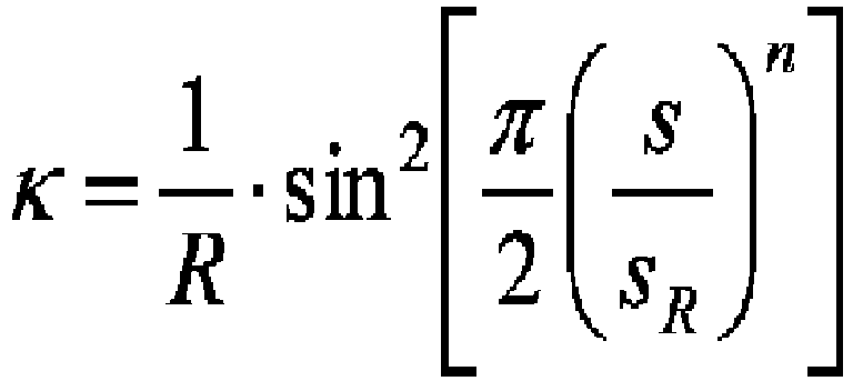
- Here, it is defined that a curvature κ of a transition curve changes by the following function.
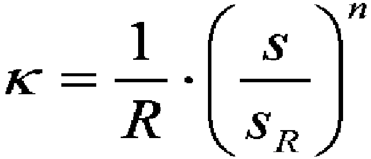
- Here, s represents a length of a curve, sR represents a length of a transition curve, R represents a pitch circle radius of a rotation conveyance body, and n represents a parameter showing a degree of change in curvature.
- The transition curve c3 is represented by
mathematical formula 3.
- Here, β represents a parameter showing a degree of change in curvature, and a length s of a curve is calculated by mathematical formula 3-1.

- Further, a curvature κ of a curve is calculated by mathematical formula 3-2.

- From mathematical formulae 3-1 and 3-2, parameters t and α can be determined based on a length of a transition curve and a pitch circle radius of a rotation conveyance body relative to any value of a parameter β showing a degree of change in curvature. Accordingly, the transition curve c3 can be calculated by
mathematical formula 3. - The transition curve c4 is represented by
mathematical formula 4.
- Here, it is defined that a curvature κ of a transition curve changes by the following function.

- Here, s represents a length of a curve (parameter), sR represents a length of a transition curve, R represents a pitch circle radius of a rotation conveyance body, and n represents a parameter showing a degree of change in curvature.
-
Fig. 3(a) shows a change in curvature relative to a length along a curve when each of the above transition curves c1 to c4 is applied to a transition track for the transfer from the circular orbit to the circular orbit between the seamingturret 1 having the pitch circle radius R1 and thedischarge turret 2 having the pitch circle radius R2, andFig. 3(b) shows a speed diagram in which the speed at that time continuously varies. - In the embodiment, the seaming
turret 1 and thedischarge turret 2 are placed as in the related art such that a distance L between the axes O1 and O2 of the turrets satisfies L = R1 + R20 when the pitch circle radius of the seamingturret 1 is represented as R1 and the pitch circle radius of thedischarge turret 2 is represented as R20. Further, theouter guide 6 and theinner guide 7, each of which has a guide surface formed by an offset transition curve obtained by offsetting a transition curve to move the axis of the can body from the seamingturret 1 to thedischarge turret 2 along any of the above transition tracks according to the size of the article, are placed such that a gap K relative to a diameter D (pocket fitting position) of the can body satisfies K ≥ D. Note that theouter guide 6 and theinner guide 7 are placed along both sides of the transition track in the embodiment, but are not necessarily placed on both sides. It is also possible to place the guide only on one of the sides or place the inner guide only at a half part of the transition track and the outer guide only at another half part of the transition track. - As shown in
Fig. 3 , each of the curves starts with thecurvature 1/R1 of theturret 1 at a position at which the transfer from theturret 1 starts, and coincides with the curvature (-1/R2) of thedischarge turret 2 at a position at which the transfer to thedischarge turret 2 ends. Between these positions, the curvature continuously varies. As a result, centrifugal acceleration applied to the can body varies continuously and smoothly to lessen an impact. In addition, the peripheral speed v1 of the seamingturret 1 continuously decelerates to the peripheral speed v2 of thedischarge turret 2 to continuously vary the acceleration in the conveyance direction. - In
Fig. 3(a) , the vertical axis represents the curvature, and the horizontal axis represents the length of the transition track (curve). In addition,Fig. 3(b) shows a change in conveyance speed, by which to indicate that the conveyance speed v1 at the seamingturret 1 decelerates smoothly and continuously to the conveyance speed v2 at thedischarge turret 2 on the transition track to transfer the can body to thedischarge turret 2. - Note that different transition curves can also be used between the section in which the curvature starts with the
curvature 1/R1 of theturret 1 and becomes zero and the section in which the curvature starts with zero and coincides with the curvature (-1/R2) of thedischarge turret 2. For example, the transition curve c1 whose curvature changes in proportion to the length of the curve may be used in the section in which the curvature starts with thecurvature 1/R1 of theturret 1 and becomes zero, and the transition curve c2 whose curvature changes in a curve relative to the length of the curve may be used in the section in which the curvature starts with zero and coincides with the curvature (-1/R2) of thedischarge turret 2. - As shown in
Fig. 1 , arc-shaped opening ends 15 and 16 of thepockets 4 of thedischarge turret 2 can be formed to protrude outward from the pitch circle radius R2 corresponding to an amount at which the pitch circle radius R2 is smaller than the conventional pitch circle radius R20. - Note that a diagram 17 in
Fig. 1(b) shows the track of a container moving away from thepocket 3 of the seamingturret 1, and a tangential direction and a normal line direction with a pitch circle relative to the axis O1 passing through the center of thepocket 3 are represented as xH and yH, respectively. Similarly, a diagram 18 inFig. 1(c) shows the track of a container moving into thepocket 4 of thedischarge turret 2, a tangential direction and a normal line direction with a pitch circle relative to the axis O2 passing through the center of thepocket 4 are represented as xD and yD, respectively. Based on these directions, the shapes of the pockets and the arc-shaped opening ends of the respective turrets can be determined. - Note that in the embodiment, the arc-shaped opening ends of the
pockets 4 of thedischarge turret 2 are formed so as to protrude from the pitch circle radius R2 in order to more reliably transfer the article, but such configuration is not limiting and the arc-shaped opening ends of thepockets 3 of the seamingturret 1 may protrude outward from the pitch circle radius, or the arc-shaped opening ends of the pockets of both turrets may protrude. - As described above, the present invention makes it possible to continuously and smoothly vary acceleration applied to can bodies in the process of conveying the can bodies from a circular orbit to a circular orbit. As a result, it becomes possible to more stably convey articles such as containers than ever before in high-speed production, whereby the occurrence of problems such as deformation and scratches caused by a contact with conveyance guides or the like can be reduced. In addition, the present invention is constituted by reducing the pitch circle radius of one of turrets without changing the distance between the axes of the turrets in conventional devices for conveying articles between the turrets, and can be achieved by simply modifying existing devices or facilities.
- Note that the present invention is applied to the part between the seaming turret and the discharge turret of the can seamer. However, it is also possible to apply the present invention not only to the above embodiment but also to, for example, various facilities such as neckers and trimmers in lines for manufacturing can bodies or the transfer and conveyance of articles between various turrets in lines for manufacturing plastic bottles, paper containers, or the like as the transfer of the articles from a circular orbit to a circular orbit.
- The present invention is high in industrial applicability as a method and a device for conveying articles in which the articles are transferred from a circular orbit to a circular orbit without damaging the conveyed articles.
Claims (9)
- A method for conveying an article in which the article is transferred from circle conveyance to circle conveyance between rotation conveyance bodies, wherein
the rotation conveyance bodies are placed so as to have a prescribed gap between pitch circles thereof, and
the article is conveyed along a transition curve of which curvature continuously varies from a pitch circle curvature of the rotation conveyance body before the transfer to a pitch circle curvature of the rotation conveyance body after the transfer between both the pitch circles. - The method for conveying the article according to claim 1, wherein
circular pitches between adjacent pockets of the rotation conveyance bodies are different from each other, and
a conveyance speed between the rotation conveyance bodies continuously varies from a peripheral speed of the circle conveyance before the transfer to a peripheral speed of the circle conveyance after the transfer. - The method for conveying the article according to claim 1, wherein
a ratio between angular speeds of the rotation conveyance bodies is equal to inverse numbers of the number of pockets of the respective rotation conveyance bodies. - The method for conveying the article according to claim 1, wherein
the article is conveyed between the rotation conveyance bodies along a conveyance guide having a guide surface of an offset transition curve obtained by offsetting the transition curve. - The method for conveying the article according to any of claims 1 to 4, wherein
the transition curve is represented by any of curves c1 to c4 calculated by any of following mathematical formulae 1 to 4:


- A device for conveying an article in which the article is transferred from circle conveyance to circle conveyance between rotation conveyance bodies, the device comprising:a transferring-side rotation conveyance body having pockets at even intervals at an outer peripheral part thereof; anda transferred-side rotation conveyance body having pockets at even intervals at an outer peripheral part thereof, whereinthe transferring-side rotation conveyance body and the transferred-side rotation conveyance body are placed so as to have a prescribed gap between pitch circles of the circle conveyance thereof,a conveyance guide for conveying the article along a prescribed track between the transferring-side rotation conveyance body and the transferred-side rotation conveyance body is provided, anda guide surface of the conveyance guide has a shape of an offset transition curve obtained by offsetting a transition curve of which curvature continuously varies from a pitch circle curvature of the circle conveyance before the transfer to a pitch circle curvature of the circle conveyance after the transfer.
- The device for conveying the article according to claim 6, wherein
the transferring-side rotation conveyance body and the transferred-side rotation conveyance body have a reduced pitch circle radius in one of the rotation conveyance bodies without a change in positions of axes of virtual rotation conveyance bodies that transfer the article with pitch circles thereof contacting each other,
a conveyance speed between the rotation conveyance bodies continuously varies from a peripheral speed of the circle conveyance before the transfer to a peripheral speed of the circle conveyance after the transfer, and
a ratio between angular speeds of the transferring-side rotation conveyance body and the transferred-side rotation conveyance body is equal to a ratio between inverse numbers of the number of pockets of the respective rotation conveyance bodies. - The device for conveying the article according to claim 6 or 7, wherein
the transition curve is represented by any of curves c1 to c4 calculated by any of following mathematical formulae 1 to 4


- The device for conveying the article according to claim 8, wherein
the pockets of the rotation conveyance bodies form article guide parts of which arc-shaped opening ends protrude outward from the corresponding pitch circles, and
the article guide parts and the pockets are shaped so as to come in contact with the article conveyed at the conveyance speed continuously varying from the peripheral speed of the circle conveyance before the transfer to the conveyance speed of the circle conveyance after the transfer.
Applications Claiming Priority (2)
| Application Number | Priority Date | Filing Date | Title |
|---|---|---|---|
| JP2014163094A JP6424511B2 (en) | 2014-08-08 | 2014-08-08 | Method of conveying articles and apparatus therefor |
| PCT/JP2015/069774 WO2016021364A1 (en) | 2014-08-08 | 2015-07-09 | Article conveying method and device therefor |
Publications (2)
| Publication Number | Publication Date |
|---|---|
| EP3178765A1 true EP3178765A1 (en) | 2017-06-14 |
| EP3178765A4 EP3178765A4 (en) | 2018-03-28 |
Family
ID=55263638
Family Applications (1)
| Application Number | Title | Priority Date | Filing Date |
|---|---|---|---|
| EP15829731.7A Withdrawn EP3178765A4 (en) | 2014-08-08 | 2015-07-09 | Article conveying method and device therefor |
Country Status (5)
| Country | Link |
|---|---|
| US (1) | US9969567B2 (en) |
| EP (1) | EP3178765A4 (en) |
| JP (1) | JP6424511B2 (en) |
| CN (1) | CN106573738B (en) |
| WO (1) | WO2016021364A1 (en) |
Cited By (2)
| Publication number | Priority date | Publication date | Assignee | Title |
|---|---|---|---|---|
| WO2019233723A1 (en) * | 2018-06-06 | 2019-12-12 | Bausch + Ströbel Maschinenfabrik Ilshofen GmbH + Co. KG | Switch device |
| EP3597572B1 (en) * | 2018-07-17 | 2026-01-21 | Krones AG | Method for allocating containers to a machine section and processing machine for containers |
Families Citing this family (5)
| Publication number | Priority date | Publication date | Assignee | Title |
|---|---|---|---|---|
| JP6802659B2 (en) * | 2016-07-29 | 2020-12-16 | 株式会社吉野工業所 | Manufacturing method of liquid storage container |
| DE102017112220A1 (en) | 2017-06-02 | 2018-12-27 | Khs Gmbh | Apparatus and method for transporting containers |
| DE102017129577A1 (en) * | 2017-12-12 | 2019-06-13 | Krones Ag | Apparatus and method for forming plastic preforms to plastic containers with tangential discharge of the plastic containers from the blow molding machine |
| DE102019117377A1 (en) * | 2019-06-27 | 2020-12-31 | Khs Gmbh | Device and method for transporting containers |
| DE102023128894A1 (en) * | 2023-10-20 | 2025-04-24 | Khs Gmbh | Device for guiding containers, transport system and plant |
Family Cites Families (12)
| Publication number | Priority date | Publication date | Assignee | Title |
|---|---|---|---|---|
| JPS5827173B2 (en) * | 1979-06-21 | 1983-06-08 | 株式会社 ロツテ | Quantitative accumulation and delivery device for plate-shaped articles |
| DE3141364C2 (en) | 1981-10-17 | 1984-12-20 | Krones Ag Hermann Kronseder Maschinenfabrik, 8402 Neutraubling | Device for distributing upright vessels |
| KR920011036B1 (en) * | 1988-04-27 | 1992-12-26 | 호까이 세이칸 가부시끼가이샤 | Apparatus for seaming can end |
| CH687248A5 (en) * | 1991-10-30 | 1996-10-31 | Mitsubishi Heavy Ind Ltd | Dosenzufuehreinrichtung for a seaming machine. |
| JPH09142649A (en) * | 1995-11-17 | 1997-06-03 | Toyo Seikan Kaisha Ltd | Container feeder for filler |
| US5772001A (en) * | 1996-04-18 | 1998-06-30 | B & H Manufacturing Company, Inc. | Star wheel system |
| JP3829578B2 (en) * | 2000-04-11 | 2006-10-04 | 東洋製罐株式会社 | Filling equipment |
| DE102011115512A1 (en) * | 2011-10-11 | 2013-04-11 | Khs Gmbh | transfer star |
| JP5630422B2 (en) * | 2011-11-08 | 2014-11-26 | 東洋製罐株式会社 | Container processing equipment |
| CA2878328C (en) * | 2012-07-04 | 2017-07-11 | Daifuku Co., Ltd. | Transport conveyer and transport facility |
| EP2754556A1 (en) * | 2013-01-11 | 2014-07-16 | Crown Packaging Technology Inc | In-feed system and method for supplying can bodies to a decorator |
| JP6716858B2 (en) * | 2015-01-15 | 2020-07-01 | 東洋製罐株式会社 | Filling and winding device and filling and winding method for can body |
-
2014
- 2014-08-08 JP JP2014163094A patent/JP6424511B2/en not_active Expired - Fee Related
-
2015
- 2015-07-09 WO PCT/JP2015/069774 patent/WO2016021364A1/en not_active Ceased
- 2015-07-09 EP EP15829731.7A patent/EP3178765A4/en not_active Withdrawn
- 2015-07-09 CN CN201580039990.2A patent/CN106573738B/en active Active
-
2017
- 2017-02-07 US US15/426,248 patent/US9969567B2/en not_active Expired - Fee Related
Cited By (5)
| Publication number | Priority date | Publication date | Assignee | Title |
|---|---|---|---|---|
| WO2019233723A1 (en) * | 2018-06-06 | 2019-12-12 | Bausch + Ströbel Maschinenfabrik Ilshofen GmbH + Co. KG | Switch device |
| CN111372877A (en) * | 2018-06-06 | 2020-07-03 | 鲍施+施特勒贝尔机械伊尔斯霍芬有限两合公司 | diversion equipment |
| US11292673B2 (en) | 2018-06-06 | 2022-04-05 | Bausch + Ströbel Maschinenfabrik Ilshofen GmbH + Co. KG | Switch device |
| CN111372877B (en) * | 2018-06-06 | 2022-05-17 | 鲍施+施特勒贝尔机械伊尔斯霍芬有限两合公司 | diversion equipment |
| EP3597572B1 (en) * | 2018-07-17 | 2026-01-21 | Krones AG | Method for allocating containers to a machine section and processing machine for containers |
Also Published As
| Publication number | Publication date |
|---|---|
| US20170152114A1 (en) | 2017-06-01 |
| EP3178765A4 (en) | 2018-03-28 |
| JP2016037375A (en) | 2016-03-22 |
| US9969567B2 (en) | 2018-05-15 |
| JP6424511B2 (en) | 2018-11-21 |
| CN106573738B (en) | 2019-07-30 |
| CN106573738A (en) | 2017-04-19 |
| WO2016021364A1 (en) | 2016-02-11 |
Similar Documents
| Publication | Publication Date | Title |
|---|---|---|
| US9969567B2 (en) | Method and device for conveying articles | |
| CN109335538A (en) | Double loop wire halved belt sorter, carbel sorting and its method for sorting | |
| US10987719B2 (en) | Can filling/seaming device and can filling/seaming method | |
| US4567919A (en) | Container filling machine and process | |
| US4531995A (en) | Labeling machine for containers | |
| CN101723293A (en) | Device for transporting containers | |
| US10077179B2 (en) | Rotor of a device for forming and/or filling containers made from preforms | |
| US20170036229A1 (en) | System for spraying the inside of can bodies | |
| JP6707562B2 (en) | Method and apparatus for curling articles | |
| EP0129168B1 (en) | Device for lowering and lifting containers | |
| US20170183163A1 (en) | Belt Conveyor with Wedge Elements for Changing Curvature at Deflection Wheels | |
| US7533511B2 (en) | Beverage bottling plant for filling bottles with a liquid beverage material having a packing machine and a rotation machine for rotating packed boxes | |
| US7165667B2 (en) | Beverage bottling plant for filling beverage bottles or other beverage containers with a liquid beverage filling material and an arrangement for dividing and separating of a stream of beverage bottles or other beverage containers | |
| JP5118925B2 (en) | Device for correcting the direction of deformed containers | |
| CN214828945U (en) | Round bottle separating and conveying mechanism | |
| US20160368638A1 (en) | Transportation system | |
| CN108137246A (en) | Intermediate storage mean and the method for intermediate storage | |
| US5439095A (en) | Apparatus for serially conveying receptacle lids | |
| US11760618B2 (en) | Container-processing device | |
| CN112978656B (en) | Device for introducing or removing containers and container treatment device | |
| AU2020402848B2 (en) | Container rotator apparatus for a container manufacturing line | |
| JP3829578B2 (en) | Filling equipment | |
| US4479343A (en) | Device for feeding-in and moving-on containers to and from a rotary capping unit | |
| CN209112996U (en) | Friction drive device, halved belt sorter and carbel sorting | |
| JP4348513B2 (en) | Method and apparatus for supplying cylindrical body to intermittent rotation turret |
Legal Events
| Date | Code | Title | Description |
|---|---|---|---|
| STAA | Information on the status of an ep patent application or granted ep patent |
Free format text: STATUS: THE INTERNATIONAL PUBLICATION HAS BEEN MADE |
|
| PUAI | Public reference made under article 153(3) epc to a published international application that has entered the european phase |
Free format text: ORIGINAL CODE: 0009012 |
|
| STAA | Information on the status of an ep patent application or granted ep patent |
Free format text: STATUS: REQUEST FOR EXAMINATION WAS MADE |
|
| 17P | Request for examination filed |
Effective date: 20170221 |
|
| AK | Designated contracting states |
Kind code of ref document: A1 Designated state(s): AL AT BE BG CH CY CZ DE DK EE ES FI FR GB GR HR HU IE IS IT LI LT LU LV MC MK MT NL NO PL PT RO RS SE SI SK SM TR |
|
| AX | Request for extension of the european patent |
Extension state: BA ME |
|
| DAV | Request for validation of the european patent (deleted) | ||
| DAX | Request for extension of the european patent (deleted) | ||
| A4 | Supplementary search report drawn up and despatched |
Effective date: 20180227 |
|
| RIC1 | Information provided on ipc code assigned before grant |
Ipc: B67C 3/24 20060101ALI20180221BHEP Ipc: B65G 47/84 20060101AFI20180221BHEP |
|
| STAA | Information on the status of an ep patent application or granted ep patent |
Free format text: STATUS: EXAMINATION IS IN PROGRESS |
|
| 17Q | First examination report despatched |
Effective date: 20200207 |
|
| GRAP | Despatch of communication of intention to grant a patent |
Free format text: ORIGINAL CODE: EPIDOSNIGR1 |
|
| STAA | Information on the status of an ep patent application or granted ep patent |
Free format text: STATUS: GRANT OF PATENT IS INTENDED |
|
| INTG | Intention to grant announced |
Effective date: 20220322 |
|
| STAA | Information on the status of an ep patent application or granted ep patent |
Free format text: STATUS: THE APPLICATION IS DEEMED TO BE WITHDRAWN |
|
| 18D | Application deemed to be withdrawn |
Effective date: 20220802 |