EP3178730A1 - Aerodynamic device for motor-vehicle - Google Patents
Aerodynamic device for motor-vehicle Download PDFInfo
- Publication number
- EP3178730A1 EP3178730A1 EP15198600.7A EP15198600A EP3178730A1 EP 3178730 A1 EP3178730 A1 EP 3178730A1 EP 15198600 A EP15198600 A EP 15198600A EP 3178730 A1 EP3178730 A1 EP 3178730A1
- Authority
- EP
- European Patent Office
- Prior art keywords
- motor
- vehicle
- panel structure
- bag
- upper wall
- Prior art date
- Legal status (The legal status is an assumption and is not a legal conclusion. Google has not performed a legal analysis and makes no representation as to the accuracy of the status listed.)
- Granted
Links
Images



Classifications
-
- B—PERFORMING OPERATIONS; TRANSPORTING
- B62—LAND VEHICLES FOR TRAVELLING OTHERWISE THAN ON RAILS
- B62D—MOTOR VEHICLES; TRAILERS
- B62D35/00—Vehicle bodies characterised by streamlining
- B62D35/005—Front spoilers
-
- B—PERFORMING OPERATIONS; TRANSPORTING
- B62—LAND VEHICLES FOR TRAVELLING OTHERWISE THAN ON RAILS
- B62D—MOTOR VEHICLES; TRAILERS
- B62D37/00—Stabilising vehicle bodies without controlling suspension arrangements
- B62D37/02—Stabilising vehicle bodies without controlling suspension arrangements by aerodynamic means
-
- F—MECHANICAL ENGINEERING; LIGHTING; HEATING; WEAPONS; BLASTING
- F15—FLUID-PRESSURE ACTUATORS; HYDRAULICS OR PNEUMATICS IN GENERAL
- F15D—FLUID DYNAMICS, i.e. METHODS OR MEANS FOR INFLUENCING THE FLOW OF GASES OR LIQUIDS
- F15D1/00—Influencing flow of fluids
- F15D1/10—Influencing flow of fluids around bodies of solid material
- F15D1/12—Influencing flow of fluids around bodies of solid material by influencing the boundary layer
-
- C—CHEMISTRY; METALLURGY
- C02—TREATMENT OF WATER, WASTE WATER, SEWAGE, OR SLUDGE
- C02F—TREATMENT OF WATER, WASTE WATER, SEWAGE, OR SLUDGE
- C02F1/00—Treatment of water, waste water, or sewage
- C02F1/46—Treatment of water, waste water, or sewage by electrochemical methods
- C02F1/461—Treatment of water, waste water, or sewage by electrochemical methods by electrolysis
- C02F1/467—Treatment of water, waste water, or sewage by electrochemical methods by electrolysis by electrochemical disinfection; by electrooxydation or by electroreduction
- C02F1/4672—Treatment of water, waste water, or sewage by electrochemical methods by electrolysis by electrochemical disinfection; by electrooxydation or by electroreduction by electrooxydation
-
- C—CHEMISTRY; METALLURGY
- C02—TREATMENT OF WATER, WASTE WATER, SEWAGE, OR SLUDGE
- C02F—TREATMENT OF WATER, WASTE WATER, SEWAGE, OR SLUDGE
- C02F1/00—Treatment of water, waste water, or sewage
- C02F1/72—Treatment of water, waste water, or sewage by oxidation
- C02F1/78—Treatment of water, waste water, or sewage by oxidation with ozone
-
- C—CHEMISTRY; METALLURGY
- C02—TREATMENT OF WATER, WASTE WATER, SEWAGE, OR SLUDGE
- C02F—TREATMENT OF WATER, WASTE WATER, SEWAGE, OR SLUDGE
- C02F1/00—Treatment of water, waste water, or sewage
- C02F1/46—Treatment of water, waste water, or sewage by electrochemical methods
- C02F1/461—Treatment of water, waste water, or sewage by electrochemical methods by electrolysis
- C02F1/46104—Devices therefor; Their operating or servicing
- C02F1/46109—Electrodes
- C02F2001/46133—Electrodes characterised by the material
- C02F2001/46138—Electrodes comprising a substrate and a coating
- C02F2001/46147—Diamond coating
-
- C—CHEMISTRY; METALLURGY
- C02—TREATMENT OF WATER, WASTE WATER, SEWAGE, OR SLUDGE
- C02F—TREATMENT OF WATER, WASTE WATER, SEWAGE, OR SLUDGE
- C02F2201/00—Apparatus for treatment of water, waste water or sewage
- C02F2201/46—Apparatus for electrochemical processes
- C02F2201/461—Electrolysis apparatus
- C02F2201/46105—Details relating to the electrolytic devices
- C02F2201/46115—Electrolytic cell with membranes or diaphragms
-
- C—CHEMISTRY; METALLURGY
- C02—TREATMENT OF WATER, WASTE WATER, SEWAGE, OR SLUDGE
- C02F—TREATMENT OF WATER, WASTE WATER, SEWAGE, OR SLUDGE
- C02F2201/00—Apparatus for treatment of water, waste water or sewage
- C02F2201/46—Apparatus for electrochemical processes
- C02F2201/461—Electrolysis apparatus
- C02F2201/46105—Details relating to the electrolytic devices
- C02F2201/4612—Controlling or monitoring
- C02F2201/46125—Electrical variables
- C02F2201/4613—Inversing polarity
-
- C—CHEMISTRY; METALLURGY
- C02—TREATMENT OF WATER, WASTE WATER, SEWAGE, OR SLUDGE
- C02F—TREATMENT OF WATER, WASTE WATER, SEWAGE, OR SLUDGE
- C02F2201/00—Apparatus for treatment of water, waste water or sewage
- C02F2201/46—Apparatus for electrochemical processes
- C02F2201/461—Electrolysis apparatus
- C02F2201/46105—Details relating to the electrolytic devices
- C02F2201/4616—Power supply
- C02F2201/4617—DC only
-
- C—CHEMISTRY; METALLURGY
- C02—TREATMENT OF WATER, WASTE WATER, SEWAGE, OR SLUDGE
- C02F—TREATMENT OF WATER, WASTE WATER, SEWAGE, OR SLUDGE
- C02F2209/00—Controlling or monitoring parameters in water treatment
- C02F2209/20—Total organic carbon [TOC]
-
- C—CHEMISTRY; METALLURGY
- C02—TREATMENT OF WATER, WASTE WATER, SEWAGE, OR SLUDGE
- C02F—TREATMENT OF WATER, WASTE WATER, SEWAGE, OR SLUDGE
- C02F2209/00—Controlling or monitoring parameters in water treatment
- C02F2209/22—O2
-
- C—CHEMISTRY; METALLURGY
- C02—TREATMENT OF WATER, WASTE WATER, SEWAGE, OR SLUDGE
- C02F—TREATMENT OF WATER, WASTE WATER, SEWAGE, OR SLUDGE
- C02F2209/00—Controlling or monitoring parameters in water treatment
- C02F2209/23—O3
-
- C—CHEMISTRY; METALLURGY
- C02—TREATMENT OF WATER, WASTE WATER, SEWAGE, OR SLUDGE
- C02F—TREATMENT OF WATER, WASTE WATER, SEWAGE, OR SLUDGE
- C02F2307/00—Location of water treatment or water treatment device
- C02F2307/06—Mounted on or being part of a faucet, shower handle or showerhead
-
- Y—GENERAL TAGGING OF NEW TECHNOLOGICAL DEVELOPMENTS; GENERAL TAGGING OF CROSS-SECTIONAL TECHNOLOGIES SPANNING OVER SEVERAL SECTIONS OF THE IPC; TECHNICAL SUBJECTS COVERED BY FORMER USPC CROSS-REFERENCE ART COLLECTIONS [XRACs] AND DIGESTS
- Y02—TECHNOLOGIES OR APPLICATIONS FOR MITIGATION OR ADAPTATION AGAINST CLIMATE CHANGE
- Y02T—CLIMATE CHANGE MITIGATION TECHNOLOGIES RELATED TO TRANSPORTATION
- Y02T10/00—Road transport of goods or passengers
- Y02T10/80—Technologies aiming to reduce greenhouse gasses emissions common to all road transportation technologies
- Y02T10/82—Elements for improving aerodynamics
Definitions
- the present invention relates to an aerodynamic device for a motor-vehicle, of the type wherein a panel structure is provided under the front part of the motor-vehicle and the panel structure is movable between a raised position and a lowered position.
- An aerodynamic device of this type is known for example from document US 2004/0113457 A1 .
- the panel structure of the device which is movable between a raised position and a lowered position, has the main function of reducing the space between the lower surface of the motor-vehicle and the road when the vehicle has a speed which is higher than a threshold value, in order to achieve a depression aerodynamic effect which presses the vehicle on the road.
- the panel structure can be maintained by spring means in a raised position when the motor-vehicle is moving instead at relatively low speed, in such a way as to enable the overcoming of obstacles present on the road.
- the object of the present invention is to provide an aerodynamic device of the type indicated above which presents a simple constructive solution, which is of low cost and at the same time results to be efficient and reliable during its operation.
- an aerodynamic device for a motor-vehicle of the type indicated in the preamble of claim 1 characterized in that said aerodynamic device further comprises a bag structure arranged inside said cavity for receiving in its interior a portion of said airflow, in such a way that above said predetermined threshold value of the motor-vehicle speed, said bag structure is inflated and pushes said panel structure towards its lowered position.
- the device according to the invention further comprises an intermediate wall placed between said upper wall and said panel structure, having its front edge rigidly fixed to the motor-vehicle bumper, in which said upper wall and said intermediate wall define a duct for directing said airflow inside said bag structure, extending starting from an inlet opening located on the front surface of the motor-vehicle.
- the bag structure has a mouth connected to, and in communication with, a terminal end of said directing duct, in such a way that said duct conveys said airflow inside said bag structure.
- the bag structure comprises a first outer bag element having an upper portion connected to said upper wall of the device and having a lower portion connected to said panel structure and further comprises a second inner bag element, wherein said outer bag element and said inner bag element together define said mouth connected to, and in communication with, a terminal end of said directing duct, in such a way that said duct conveys said airflow inside said bag structure.
- the aerodynamic device according to the present invention results simple, of low cost, efficient and reliable in its operation.
- the aerodynamic device according to the invention also enables the obtaining of the desired aerodynamic effect ensuring at the same time the device integrity in any travel condition.
- the present invention relates to an aerodynamic device for a motor-vehicle.
- number 1 generally designates an aerodynamic device arranged under the body of the motor-vehicle.
- the device 1 comprises a panel structure 2 located under the front part of the motor-vehicle, wherein the panel structure 2 results movable between a raised position (illustrated in figure 5 ) and a lowered position (illustrated in figure 6 ).
- the panel structure 2 is adapted to be moved towards a lowered position when the speed of the motor-vehicle exceeds a predetermined threshold value, due to an airflow which invests the motor-vehicle and it is elastically biassed towards a raised position by one or more spring means.
- the panel structure 2 extends transversally below the body of the motor-vehicle and presents a central portion 21 with opposite sides in which there are two flexible panels 22.
- the central portion 21 is made of a plastic material having characteristics of high stiffness, while the flexible panels 22 connected to the structure of the motor-vehicle are preferably made of a plastic or elastomeric material, so as to follow the upward or downward movement of the central portion 21 of the aerodynamic device 1.
- the panel structure 2 and in particular its central portion 21 is pivotally mounted on the motor-vehicle bumper around a transverse axis I with respect to the longitudinal direction of the motor-vehicle.
- the panel structure 2 is elastically biassed towards a raised position by spring means which in the herein illustrated embodiment are two springs 6 placed at the ends of said central portion 21 of said panel structure 2. Therefore the springs 6 have the function of elastic return of the panel structure 2 towards its raised position and in particular with reference to figures 3 and 4 , each spring 6 is a coil spring wrapped around a pivot pin 7 which is rigidly mounted on the motor-vehicle bumper.
- the coil springs 6 present two opposite ends 61,62 which are respectively constrained to the lower surface of the panel structure 2 in such a way as to make easier the return of the panel structure 2 towards its raised position and towards the motor-vehicle bumper.
- the aerodynamic device 1 further comprises an upper wall 4.
- the upper wall 4 is a fixed wall with respect to the motor-vehicle body and it is placed above the panel structure 2 so as to define a cavity C together the panel structure 2.
- the front part of the upper wall 4 and the front part of the panel structure 2 are vertically spaced from each other, while their rear parts result to be adjacent to each other in such a way that the cavity C formed between the upper wall 4 and the panel structure 2 vertically shrinks in the direction of the rear part of the motor-vehicle.
- the aerodynamic device 1 further comprises a bag structure 5 arranged inside of the cavity C between the panel structure 2 and the upper wall 4.
- the panel structure 2 is adapted to be moved towards a lowered position due to an airflow which invests the motor-vehicle when the motor-vehicle speed exceeds a predetermined threshold value.
- the bag structure 5 is therefore arranged inside of said cavity C in order to receive therewithin a portion of the airflow which invests the motor-vehicle, in such a way that above a predetermined threshold value of the motor-vehicle speed, the bag structure 5 is inflated and pushes the panel structure 2 towards its lowered position.
- the device 1 further comprises an intermediate wall 8 interposed between the upper wall 4 and the panel structure 2.
- the intermediate wall 8 presents its front edge rigidly fixed to the motor-vehicle bumper and defines, with the upper wall 4, a duct 12 adapted to direct the airflow inside the cavity C.
- the duct 12 presents a first end in correspondence of a motor-vehicle front grid 12A provided with horizontal fins (as illustrated in the drawings) or vertical fins.
- the duct 12 presents a terminal end 13 connected to, and in communication with, a mouth 13 of the bag structure 5.
- the duct 12 defined between the upper wall 4 and the intermediate wall 8 conveys the airflow which invests the motor-vehicle during travel inside the bag structure 5 which, as a consequence of the inflation, pushes the panel structure 2 in its lowered position (as illustrated in figure 8 ) overcoming in this way the elastic resistance of the springs 6.
- the bag structure 5 comprises a first outer bag element 51 and a second inner bag element 52.
- the outer element 51 presents an upper portion connected to the upper wall 4 of the device 1 and presents a lower portion connected to the panel structure 2.
- the second inner element 52 which is provided inside of the first outer element 51, defines with the outer element 51 the mouth 13 connected to, and in communication with, the terminal end of the directing duct 12 of the airflow which invests the motor-vehicle.
- the intermediate wall 8 presents a longitudinal extension lower than the longitudinal extension of the upper wall 4 and of the panel structure 2 in such a way as to enable the arrangement of the bag structure 5 with its mouth 13 connected to the terminal end of the duct 12.
- the intermediate wall 8 of the aerodynamic device 1 further presents a plurality of openings A along its longitudinal extension.
- Such openings A are provided for the drainage of any water which eventually can enter inside the duct 12 during the operation of the motor-vehicle. In this way entrance of water inside the bag structure 5 is avoided considering that the entrance of water could affect the proper operation of the device 1.
- figure 7 illustrates the device 1 according to the invention in its raised position. Such condition occurs at low speed of the motor-vehicle in such a way as to enable the overcoming of obstacles present on the road.
- Figure 8 illustrates instead the device 1 according to the invention in its lowered position which occurs as a consequence of the inflation of the bag structure 5 after passing a predetermined threshold value of the motor-vehicle speed.
- a predetermined threshold value of the motor-vehicle speed After passing the predetermined threshold value of the motor-vehicle speed, an airflow enters inside the duct 12 and inside the bag structure 5 having its mouth connected to the terminal end of the duct 12.
- the bag structure 5 is inflated and pushes the panel structure 2 towards its lowered position overcoming the resistance of the spring 6 which tends to return the panel structure 2 towards the top.
- the bag structure 5 starts to deflate and consequently the spring 6 elastically biases the panel structure 2 to its raised position illustrated in figure 7 .
- the aerodynamic device 1 according to the invention has the advantage of improving the aerodynamic performances of the motor-vehicle while being at the same time simple, efficient reliable in its operation and of low cost.
- the aerodynamic device 1 is adapted to be mounted with simple operations also on motor-vehicles in which the aerodynamic device is not originally provided. Furthermore, by means of few modification to the constructive elements of the device 1, the device can be installed on motor-vehicle of different classes.
Landscapes
- Engineering & Computer Science (AREA)
- Mechanical Engineering (AREA)
- Chemical & Material Sciences (AREA)
- Combustion & Propulsion (AREA)
- Transportation (AREA)
- Physics & Mathematics (AREA)
- Fluid Mechanics (AREA)
- General Engineering & Computer Science (AREA)
- Body Structure For Vehicles (AREA)
Abstract
Description
- The present invention relates to an aerodynamic device for a motor-vehicle, of the type wherein a panel structure is provided under the front part of the motor-vehicle and the panel structure is movable between a raised position and a lowered position.
- An aerodynamic device of this type is known for example from document
US 2004/0113457 A1 . The panel structure of the device, which is movable between a raised position and a lowered position, has the main function of reducing the space between the lower surface of the motor-vehicle and the road when the vehicle has a speed which is higher than a threshold value, in order to achieve a depression aerodynamic effect which presses the vehicle on the road. At the same time the panel structure can be maintained by spring means in a raised position when the motor-vehicle is moving instead at relatively low speed, in such a way as to enable the overcoming of obstacles present on the road. - The object of the present invention is to provide an aerodynamic device of the type indicated above which presents a simple constructive solution, which is of low cost and at the same time results to be efficient and reliable during its operation.
- The above mentioned objects are achieved by means of an aerodynamic device for a motor-vehicle of the type indicated in the preamble of
claim 1, characterized in that said aerodynamic device further comprises a bag structure arranged inside said cavity for receiving in its interior a portion of said airflow, in such a way that above said predetermined threshold value of the motor-vehicle speed, said bag structure is inflated and pushes said panel structure towards its lowered position. - In a preferred embodiment the device according to the invention further comprises an intermediate wall placed between said upper wall and said panel structure, having its front edge rigidly fixed to the motor-vehicle bumper, in which said upper wall and said intermediate wall define a duct for directing said airflow inside said bag structure, extending starting from an inlet opening located on the front surface of the motor-vehicle.
- Furthermore, again according to a preferred embodiment, the bag structure has a mouth connected to, and in communication with, a terminal end of said directing duct, in such a way that said duct conveys said airflow inside said bag structure.
- According to a further characteristic, the bag structure comprises a first outer bag element having an upper portion connected to said upper wall of the device and having a lower portion connected to said panel structure and further comprises a second inner bag element, wherein said outer bag element and said inner bag element together define said mouth connected to, and in communication with, a terminal end of said directing duct, in such a way that said duct conveys said airflow inside said bag structure.
- Thanks to the above mentioned characteristics, the aerodynamic device according to the present invention results simple, of low cost, efficient and reliable in its operation. The aerodynamic device according to the invention also enables the obtaining of the desired aerodynamic effect ensuring at the same time the device integrity in any travel condition.
- Further features and advantages of the invention will become apparent from the following description with reference to the annexed figures, given purely by way of non limiting example, in which:
-
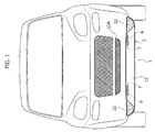
figure 1 is a front view of a motor-vehicle having the aerodynamic device according to the present invention; -
figure 2 is a side-view of the motor-vehicle and of the device illustrated infigure 1 ; -
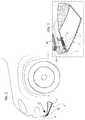
figure 3 is a partial perspective view of the device illustrated infigures 1 and2 ; -
figure 4 is a bottom view of the motor-vehicle and of the device illustrated infigures 1 and2 ; -
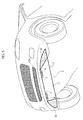
figures 5 and6 are two perspective views from the bottom of the motor-vehicle illustrated infigures 1 ,2 and4 with the device respectively in its raised position and in its lowered position, -
figures 7 and8 are two cross-sectional views of the device illustrated in the previous figures, respectively with the device in its raised position and in its lowered position. - In the following description various specific details are illustrated, aimed to a better understanding of the embodiments. The embodiments can be implemented without one or more of the specific details, or with other methods, components, or materials etc. In other cases, structures, materials or known operations are not shown or described in detail in order to avoid that various aspects of the embodiment may become obscure. The references herein used are only for convenience and therefore do not define the extent of protection or the scope of the embodiments.
- As mentioned above, the present invention relates to an aerodynamic device for a motor-vehicle.
- With reference to
figures 1-8 ,number 1 generally designates an aerodynamic device arranged under the body of the motor-vehicle. Thedevice 1 comprises apanel structure 2 located under the front part of the motor-vehicle, wherein thepanel structure 2 results movable between a raised position (illustrated infigure 5 ) and a lowered position (illustrated infigure 6 ). Than thepanel structure 2 is adapted to be moved towards a lowered position when the speed of the motor-vehicle exceeds a predetermined threshold value, due to an airflow which invests the motor-vehicle and it is elastically biassed towards a raised position by one or more spring means. - As illustrated in
figures 1 and2 thepanel structure 2 extends transversally below the body of the motor-vehicle and presents acentral portion 21 with opposite sides in which there are twoflexible panels 22. Thecentral portion 21 is made of a plastic material having characteristics of high stiffness, while theflexible panels 22 connected to the structure of the motor-vehicle are preferably made of a plastic or elastomeric material, so as to follow the upward or downward movement of thecentral portion 21 of theaerodynamic device 1. - With reference to
figures 1 ,2 and 3 , thepanel structure 2 and in particular itscentral portion 21 is pivotally mounted on the motor-vehicle bumper around a transverse axis I with respect to the longitudinal direction of the motor-vehicle. Thepanel structure 2 is elastically biassed towards a raised position by spring means which in the herein illustrated embodiment are twosprings 6 placed at the ends of saidcentral portion 21 of saidpanel structure 2. Therefore thesprings 6 have the function of elastic return of thepanel structure 2 towards its raised position and in particular with reference tofigures 3 and4 , eachspring 6 is a coil spring wrapped around apivot pin 7 which is rigidly mounted on the motor-vehicle bumper. Thecoil springs 6 present twoopposite ends panel structure 2 in such a way as to make easier the return of thepanel structure 2 towards its raised position and towards the motor-vehicle bumper. - With reference to
figures 7 and8 which show two cross-section views of thedevice 1 respectively in its raised position and in its lowered position, theaerodynamic device 1 further comprises anupper wall 4. Theupper wall 4 is a fixed wall with respect to the motor-vehicle body and it is placed above thepanel structure 2 so as to define a cavity C together thepanel structure 2. Again, with reference tofigures 7 and8 the front part of theupper wall 4 and the front part of thepanel structure 2 are vertically spaced from each other, while their rear parts result to be adjacent to each other in such a way that the cavity C formed between theupper wall 4 and thepanel structure 2 vertically shrinks in the direction of the rear part of the motor-vehicle. - Again with reference to
figures 7 and8 , theaerodynamic device 1 further comprises abag structure 5 arranged inside of the cavity C between thepanel structure 2 and theupper wall 4. - As previously indicated, the
panel structure 2 is adapted to be moved towards a lowered position due to an airflow which invests the motor-vehicle when the motor-vehicle speed exceeds a predetermined threshold value. Thebag structure 5 is therefore arranged inside of said cavity C in order to receive therewithin a portion of the airflow which invests the motor-vehicle, in such a way that above a predetermined threshold value of the motor-vehicle speed, thebag structure 5 is inflated and pushes thepanel structure 2 towards its lowered position. - Again with reference to
figures 7 ,8 , in order to convey the airflow inside thebag structure 5, thedevice 1 further comprises anintermediate wall 8 interposed between theupper wall 4 and thepanel structure 2. Theintermediate wall 8 presents its front edge rigidly fixed to the motor-vehicle bumper and defines, with theupper wall 4, aduct 12 adapted to direct the airflow inside the cavity C. Theduct 12 presents a first end in correspondence of a motor-vehiclefront grid 12A provided with horizontal fins (as illustrated in the drawings) or vertical fins. Theduct 12 presents aterminal end 13 connected to, and in communication with, amouth 13 of thebag structure 5. In this way, theduct 12 defined between theupper wall 4 and theintermediate wall 8 conveys the airflow which invests the motor-vehicle during travel inside thebag structure 5 which, as a consequence of the inflation, pushes thepanel structure 2 in its lowered position (as illustrated infigure 8 ) overcoming in this way the elastic resistance of thesprings 6. - Again with reference to
figures 7 ,8 , thebag structure 5 comprises a firstouter bag element 51 and a secondinner bag element 52. Theouter element 51 presents an upper portion connected to theupper wall 4 of thedevice 1 and presents a lower portion connected to thepanel structure 2. The secondinner element 52, which is provided inside of the firstouter element 51, defines with theouter element 51 themouth 13 connected to, and in communication with, the terminal end of thedirecting duct 12 of the airflow which invests the motor-vehicle. Again with reference tofigures 7 ,8 theintermediate wall 8 presents a longitudinal extension lower than the longitudinal extension of theupper wall 4 and of thepanel structure 2 in such a way as to enable the arrangement of thebag structure 5 with itsmouth 13 connected to the terminal end of theduct 12. Theintermediate wall 8 of theaerodynamic device 1 further presents a plurality of openings A along its longitudinal extension. Such openings A are provided for the drainage of any water which eventually can enter inside theduct 12 during the operation of the motor-vehicle. In this way entrance of water inside thebag structure 5 is avoided considering that the entrance of water could affect the proper operation of thedevice 1. - As previously indicated,
figure 7 illustrates thedevice 1 according to the invention in its raised position. Such condition occurs at low speed of the motor-vehicle in such a way as to enable the overcoming of obstacles present on the road. -
Figure 8 illustrates instead thedevice 1 according to the invention in its lowered position which occurs as a consequence of the inflation of thebag structure 5 after passing a predetermined threshold value of the motor-vehicle speed. After passing the predetermined threshold value of the motor-vehicle speed, an airflow enters inside theduct 12 and inside thebag structure 5 having its mouth connected to the terminal end of theduct 12. As a consequence thebag structure 5 is inflated and pushes thepanel structure 2 towards its lowered position overcoming the resistance of thespring 6 which tends to return thepanel structure 2 towards the top. - When the motor-vehicle speed returns below the predetermined threshold value, the
bag structure 5 starts to deflate and consequently thespring 6 elastically biases thepanel structure 2 to its raised position illustrated infigure 7 . - The
aerodynamic device 1 according to the invention has the advantage of improving the aerodynamic performances of the motor-vehicle while being at the same time simple, efficient reliable in its operation and of low cost. - Furthermore, the
aerodynamic device 1 is adapted to be mounted with simple operations also on motor-vehicles in which the aerodynamic device is not originally provided. Furthermore, by means of few modification to the constructive elements of thedevice 1, the device can be installed on motor-vehicle of different classes. - Naturally, while the principle of the invention remains the same, the details of construction and the embodiments may widely vary with respect to what has been described and shown purely by way of example, without departing from the scope of the invention.
Claims (11)
- Aerodynamic device (1) for a motor-vehicle, comprising:- a panel structure (2) located under the front part of the motor-vehicle and pivotally mounted around an axis (I) transverse with respect to the longitudinal direction of the motor-vehicle, said panel structure (2) being elastically biased towards a raised position and being adapted to be moved towards a lowered position when the motor-vehicle speed exceeds a predetermined threshold value, due to an airflow which invests the motor-vehicle,- an upper wall (4) which is fixed with respect to the motor-vehicle body, and placed above said panel structure (2) so as to define a cavity (C) together with said panel structure (2),
characterized in that said aerodynamic device (1) further comprises a bag structure (5) arranged inside said cavity (C) for receiving in its interior a portion of said airflow which invests the motor-vehicle during travel,
in such a way that above said predetermined threshold value of the motor-vehicle speed, said bag structure (5) is inflated and pushes said panel structure (2) towards its lowered position. - Device according to claim 1, characterized in that the front part of said upper wall (4) and the front part of said panel structure (2) are vertically spaced form each other, while the rear part of said upper wall (4) and the rear part of said panel structure (2) are adjacent to each other, in such a way that said cavity (C) vertically shrinks in the direction of the rear part of the motor-vehicle.
- Device according to claim 1 or 2, characterized in that the front part of said panel structure (2) is pivotally mounted on a motor-vehicle bumper, around a transverse axis (I) with respect to the longitudinal direction of the motor-vehicle, said device comprising at least one spring (6) having the function of elastically biasing said panel structure (2) towards said raised position.
- Device according to claim 3, characterized in that said panel structure (2) is pivotally mounted to the motor-vehicle bumper by means of at least one pivot pin (7), and in that said at least one spring (6) is a coil spring wound around said pivot pin (7) and having opposite ends (61, 62) operatively connected to the panel structure (2) and to the bumper.
- Device according to claim 3, characterized in that said device (1) further comprises an intermediate wall (8) placed between said upper wall (4) and said panel structure (2), said intermediate wall (8) having its front edge rigidly fixed to the motor-vehicle bumper, in which said upper wall (4) and said intermediate wall (8) define a duct (12) for directing said airflow inside said bag structure (5), said duct starting from an inlet opening located on the front surface of the motor-vehicle.
- Device according to claim 5, characterized in that said bag structure (5) has a mouth (13) connected to, and in communication with, a terminal end of said directing duct (12), in such a way that said duct (12) conveys said airflow inside said bag structure (5).
- Device according to claim 6, characterized in that said bag structure (5) comprises a first outer bag element (51) having an upper portion connected to said upper wall (4) of the device (1) and having a lower portion connected to said panel structure (2).
- Device according to claim 7, characterized in that said bag structure (5) further comprises a second inner bag element (52), wherein said outer bag element (51) and said inner bag element (52) together define said mouth (13) connected to, and in communication with, said terminal end of said directing duct (12) of the airflow.
- Device according to claim 5, characterized in that said intermediate wall (8) longitudinally extends inside said cavity (C) and has a longitudinal extension lower than the longitudinal extension of said panel structure (2) and of said upper wall (12).
- Device according to claim 1, characterized in that said panel structure (2) has two opposite sides connected to the motor-vehicle structure, or connected to a front bumper secured to said motor-vehicle structure, by means of two flexible panels (22).
- Device according to claim 5, characterized in that said intermediate wall (8) has at least one opening (A) along its longitudinal extension, arranged for the drainage of any water which may have entered in the directing duct (12), in such a way as to avoid the entrance of water inside said bag structure (5).
Priority Applications (2)
| Application Number | Priority Date | Filing Date | Title |
|---|---|---|---|
| EP15198600.7A EP3178730B1 (en) | 2015-12-09 | 2015-12-09 | Aerodynamic device for motor-vehicle |
| US15/346,795 US10173736B2 (en) | 2015-12-09 | 2016-11-09 | Aerodynamic device for motor-vehicle |
Applications Claiming Priority (1)
| Application Number | Priority Date | Filing Date | Title |
|---|---|---|---|
| EP15198600.7A EP3178730B1 (en) | 2015-12-09 | 2015-12-09 | Aerodynamic device for motor-vehicle |
Publications (2)
| Publication Number | Publication Date |
|---|---|
| EP3178730A1 true EP3178730A1 (en) | 2017-06-14 |
| EP3178730B1 EP3178730B1 (en) | 2019-01-30 |
Family
ID=55023857
Family Applications (1)
| Application Number | Title | Priority Date | Filing Date |
|---|---|---|---|
| EP15198600.7A Active EP3178730B1 (en) | 2015-12-09 | 2015-12-09 | Aerodynamic device for motor-vehicle |
Country Status (2)
| Country | Link |
|---|---|
| US (1) | US10173736B2 (en) |
| EP (1) | EP3178730B1 (en) |
Cited By (1)
| Publication number | Priority date | Publication date | Assignee | Title |
|---|---|---|---|---|
| EP3838724A1 (en) * | 2019-12-19 | 2021-06-23 | RENAULT s.a.s. | Motor vehicle including at least one aerodynamic deflector device |
Families Citing this family (15)
| Publication number | Priority date | Publication date | Assignee | Title |
|---|---|---|---|---|
| EP3178730B1 (en) * | 2015-12-09 | 2019-01-30 | C.R.F. Società Consortile per Azioni | Aerodynamic device for motor-vehicle |
| DE102016010321A1 (en) * | 2016-08-25 | 2018-03-01 | GM Global Technology Operations LLC (n. d. Ges. d. Staates Delaware) | Spoiler arrangement for a motor vehicle |
| FR3059978B1 (en) * | 2016-12-13 | 2019-04-19 | Valeo Systemes Thermiques | AERODYNAMIC DEFLECTOR DEVICE FOR A MOTOR VEHICLE WHEEL |
| EP3578446B1 (en) * | 2017-03-06 | 2022-08-10 | Mazda Motor Corporation | Tire deflector device |
| JP6477762B2 (en) * | 2017-03-28 | 2019-03-06 | マツダ株式会社 | Front body structure of the vehicle |
| US20200198711A1 (en) * | 2018-12-20 | 2020-06-25 | GM Global Technology Operations LLC | Piezoelectric bellow configured to control downforce |
| US11180203B2 (en) * | 2019-11-19 | 2021-11-23 | Ford Global Technologies, Llc | Active fascia splitter and engine shield |
| DE102020105085B4 (en) | 2020-02-27 | 2024-01-25 | Dr. Ing. H.C. F. Porsche Aktiengesellschaft | Adaptive front guidance element for a motor vehicle |
| CN115892257A (en) * | 2021-09-30 | 2023-04-04 | 本田技研工业株式会社 | Underbody structure |
| CN115892258A (en) * | 2021-09-30 | 2023-04-04 | 本田技研工业株式会社 | Underbody structure |
| EP4349696A1 (en) * | 2022-10-04 | 2024-04-10 | Volvo Car Corporation | Mechanical air deflector device for a vehilce |
| US12448060B2 (en) | 2023-03-08 | 2025-10-21 | Honda Motor Co., Ltd. | Pneumatic bladder aerodynamic device |
| US12576926B2 (en) | 2023-03-08 | 2026-03-17 | Honda Motor Co., Ltd. | Pneumatic bladder aerodynamic device |
| US12605988B2 (en) * | 2023-10-25 | 2026-04-21 | Fca Us Llc | Hood closure assist system |
| GB202413817D0 (en) * | 2024-09-19 | 2024-11-06 | Mclaren Automotive Ltd | Passive fluidic switch |
Citations (5)
| Publication number | Priority date | Publication date | Assignee | Title |
|---|---|---|---|---|
| DE3630645A1 (en) * | 1986-09-09 | 1988-03-10 | Daimler Benz Ag | Front panelling for vehicles, in particular private cars |
| US20040113457A1 (en) | 2002-10-02 | 2004-06-17 | Compagnie Plastic Omnium | Vehicle bumper including a spoiler hinged between three positions of stable equilibrium |
| US20080303309A1 (en) * | 2005-04-21 | 2008-12-11 | Roderick Dayton | Vehicle Air Dam System |
| DE102011111456A1 (en) * | 2011-08-30 | 2013-02-28 | Apollo Vredestein B.V. | Air guiding device for a motor vehicle |
| DE102014104156A1 (en) * | 2014-03-26 | 2015-10-01 | Dr. Ing. H.C. F. Porsche Aktiengesellschaft | Air guiding device for a motor vehicle |
Family Cites Families (12)
| Publication number | Priority date | Publication date | Assignee | Title |
|---|---|---|---|---|
| US4441751A (en) * | 1980-11-24 | 1984-04-10 | Wesley William M | Collapsible high speed extension for motor vehicles |
| IT1153678B (en) * | 1982-12-10 | 1987-01-14 | Alfa Romeo Spa | AUTOMATIC POSITIONING SPOILER FOR A VEHICLE |
| DE10160748B8 (en) * | 2001-12-11 | 2005-09-29 | Dr.Ing.H.C. F. Porsche Ag | Motor vehicle with a front part comprising a louver |
| CH703690B1 (en) * | 2004-05-10 | 2012-03-15 | Protoscar Sa | pneumatically inflatable construction element for motor vehicles. |
| NL2000328C2 (en) * | 2006-11-23 | 2008-05-26 | Vredestein Banden B V | Method for mutual bonding of molded parts from vulcanized rubber. |
| US8303025B2 (en) * | 2010-05-27 | 2012-11-06 | Strehl, Llc | Aerodynamic trucking systems |
| DE102011112514A1 (en) * | 2011-09-07 | 2013-03-07 | Apollo Vredestein B.V. | Air guiding device of a motor vehicle |
| DE102012020739B4 (en) * | 2012-10-23 | 2022-03-03 | Apollo Vredestein B.V. | Air guiding device of a motor vehicle |
| NL2009835C2 (en) * | 2012-11-19 | 2014-05-21 | Apollo Vredestein Bv | Method for manufacturing a molded article of a rubber polymer to which another article is detachably connected. |
| NL2012011C2 (en) * | 2013-12-20 | 2015-06-26 | Apollo Vredestein Bv | Vehicle front spoiler. |
| EP3178730B1 (en) * | 2015-12-09 | 2019-01-30 | C.R.F. Società Consortile per Azioni | Aerodynamic device for motor-vehicle |
| JP6394642B2 (en) * | 2016-06-13 | 2018-09-26 | トヨタ自動車株式会社 | Vehicle lower structure |
-
2015
- 2015-12-09 EP EP15198600.7A patent/EP3178730B1/en active Active
-
2016
- 2016-11-09 US US15/346,795 patent/US10173736B2/en active Active
Patent Citations (5)
| Publication number | Priority date | Publication date | Assignee | Title |
|---|---|---|---|---|
| DE3630645A1 (en) * | 1986-09-09 | 1988-03-10 | Daimler Benz Ag | Front panelling for vehicles, in particular private cars |
| US20040113457A1 (en) | 2002-10-02 | 2004-06-17 | Compagnie Plastic Omnium | Vehicle bumper including a spoiler hinged between three positions of stable equilibrium |
| US20080303309A1 (en) * | 2005-04-21 | 2008-12-11 | Roderick Dayton | Vehicle Air Dam System |
| DE102011111456A1 (en) * | 2011-08-30 | 2013-02-28 | Apollo Vredestein B.V. | Air guiding device for a motor vehicle |
| DE102014104156A1 (en) * | 2014-03-26 | 2015-10-01 | Dr. Ing. H.C. F. Porsche Aktiengesellschaft | Air guiding device for a motor vehicle |
Cited By (2)
| Publication number | Priority date | Publication date | Assignee | Title |
|---|---|---|---|---|
| EP3838724A1 (en) * | 2019-12-19 | 2021-06-23 | RENAULT s.a.s. | Motor vehicle including at least one aerodynamic deflector device |
| FR3105161A1 (en) * | 2019-12-19 | 2021-06-25 | Renault S.A.S | Motor vehicle comprising at least one aerodynamic deflector device |
Also Published As
| Publication number | Publication date |
|---|---|
| US20170166267A1 (en) | 2017-06-15 |
| US10173736B2 (en) | 2019-01-08 |
| EP3178730B1 (en) | 2019-01-30 |
Similar Documents
| Publication | Publication Date | Title |
|---|---|---|
| EP3178730B1 (en) | Aerodynamic device for motor-vehicle | |
| KR101483324B1 (en) | Corner energy absorber and bumper system | |
| CN105329327B (en) | Motor vehicles with adjustable threshold bottom girder | |
| KR101546922B1 (en) | Auxiliary material for absorbing shock of headlining of vehicle | |
| US9650077B2 (en) | Car undercover | |
| DE102011009943A1 (en) | Energy absorption system | |
| EP3006249B1 (en) | An under-body aerodynamic device for a motor-vehicle | |
| CN107539370A (en) | Front of the car enhancing structure | |
| US9610911B2 (en) | Front part of a motor vehicle and stiffening thereto | |
| GB2322602A (en) | Bumper assemblies for motor vehicles | |
| CN104071039A (en) | Seat track end cap and advancing stopping seat position sensor | |
| US3741598A (en) | Pneumatic bumper | |
| US20120074187A1 (en) | Deployable roof rack system | |
| US10766545B2 (en) | Aerodynamic deflector device for a motor vehicle wheel | |
| CN104773051A (en) | Open roof construction for a vehicle and wind deflector for use therein | |
| JP6265420B2 (en) | Vehicle bumper | |
| EP2871087A1 (en) | Deflector device for vehicle | |
| CN105438100B (en) | Vehicle front end airbag assembly and system | |
| DE112016001668T5 (en) | Collision detection device for a vehicle | |
| DE102012105662A1 (en) | Collision detection device for car, has chamber body portion whose end portion projects from one end of bumper reinforcement part with respect to vehicle width direction of side of vehicle, and pressure sensor secured to chamber portion | |
| EP2632751A1 (en) | Openable roof for a vehicle | |
| KR102231128B1 (en) | Exterior mirror device for a motor vehicle, and motor vehicle | |
| DE102004024987A1 (en) | Front pedestrian protection structure of motor vehicle has fog light holders extending from shaped sections into spoiler range, and reinforcing supports attached with shape stabilizing holder of vehicle body for deformation of spoiler range | |
| FR2862262B1 (en) | BUMPER REINFORCEMENT TO BE IMPLANTED IN THE FRONT OF A MOTOR VEHICLE. | |
| US12054114B2 (en) | Retractable aerodynamic underbody flap with force absorption by the lower support |
Legal Events
| Date | Code | Title | Description |
|---|---|---|---|
| PUAI | Public reference made under article 153(3) epc to a published international application that has entered the european phase |
Free format text: ORIGINAL CODE: 0009012 |
|
| STAA | Information on the status of an ep patent application or granted ep patent |
Free format text: STATUS: REQUEST FOR EXAMINATION WAS MADE |
|
| 17P | Request for examination filed |
Effective date: 20160822 |
|
| AK | Designated contracting states |
Kind code of ref document: A1 Designated state(s): AL AT BE BG CH CY CZ DE DK EE ES FI FR GB GR HR HU IE IS IT LI LT LU LV MC MK MT NL NO PL PT RO RS SE SI SK SM TR |
|
| AX | Request for extension of the european patent |
Extension state: BA ME |
|
| REG | Reference to a national code |
Ref country code: DE Ref legal event code: R079 Ref document number: 602015023945 Country of ref document: DE Free format text: PREVIOUS MAIN CLASS: B62D0035000000 Ipc: C02F0001467000 |
|
| GRAP | Despatch of communication of intention to grant a patent |
Free format text: ORIGINAL CODE: EPIDOSNIGR1 |
|
| STAA | Information on the status of an ep patent application or granted ep patent |
Free format text: STATUS: GRANT OF PATENT IS INTENDED |
|
| RIC1 | Information provided on ipc code assigned before grant |
Ipc: F15D 1/12 20060101ALI20180830BHEP Ipc: C02F 1/78 20060101ALI20180830BHEP Ipc: C02F 1/467 20060101AFI20180830BHEP Ipc: B62D 35/00 20060101ALI20180830BHEP Ipc: B62D 37/02 20060101ALI20180830BHEP Ipc: C02F 1/461 20060101ALI20180830BHEP |
|
| INTG | Intention to grant announced |
Effective date: 20180925 |
|
| GRAS | Grant fee paid |
Free format text: ORIGINAL CODE: EPIDOSNIGR3 |
|
| GRAA | (expected) grant |
Free format text: ORIGINAL CODE: 0009210 |
|
| STAA | Information on the status of an ep patent application or granted ep patent |
Free format text: STATUS: THE PATENT HAS BEEN GRANTED |
|
| AK | Designated contracting states |
Kind code of ref document: B1 Designated state(s): AL AT BE BG CH CY CZ DE DK EE ES FI FR GB GR HR HU IE IS IT LI LT LU LV MC MK MT NL NO PL PT RO RS SE SI SK SM TR |
|
| REG | Reference to a national code |
Ref country code: GB Ref legal event code: FG4D |
|
| REG | Reference to a national code |
Ref country code: CH Ref legal event code: EP |
|
| REG | Reference to a national code |
Ref country code: AT Ref legal event code: REF Ref document number: 1093106 Country of ref document: AT Kind code of ref document: T Effective date: 20190215 |
|
| REG | Reference to a national code |
Ref country code: IE Ref legal event code: FG4D |
|
| REG | Reference to a national code |
Ref country code: DE Ref legal event code: R096 Ref document number: 602015023945 Country of ref document: DE |
|
| REG | Reference to a national code |
Ref country code: LT Ref legal event code: MG4D |
|
| REG | Reference to a national code |
Ref country code: NL Ref legal event code: MP Effective date: 20190130 |
|
| PG25 | Lapsed in a contracting state [announced via postgrant information from national office to epo] |
Ref country code: FI Free format text: LAPSE BECAUSE OF FAILURE TO SUBMIT A TRANSLATION OF THE DESCRIPTION OR TO PAY THE FEE WITHIN THE PRESCRIBED TIME-LIMIT Effective date: 20190130 Ref country code: SE Free format text: LAPSE BECAUSE OF FAILURE TO SUBMIT A TRANSLATION OF THE DESCRIPTION OR TO PAY THE FEE WITHIN THE PRESCRIBED TIME-LIMIT Effective date: 20190130 Ref country code: NL Free format text: LAPSE BECAUSE OF FAILURE TO SUBMIT A TRANSLATION OF THE DESCRIPTION OR TO PAY THE FEE WITHIN THE PRESCRIBED TIME-LIMIT Effective date: 20190130 Ref country code: PL Free format text: LAPSE BECAUSE OF FAILURE TO SUBMIT A TRANSLATION OF THE DESCRIPTION OR TO PAY THE FEE WITHIN THE PRESCRIBED TIME-LIMIT Effective date: 20190130 Ref country code: ES Free format text: LAPSE BECAUSE OF FAILURE TO SUBMIT A TRANSLATION OF THE DESCRIPTION OR TO PAY THE FEE WITHIN THE PRESCRIBED TIME-LIMIT Effective date: 20190130 Ref country code: LT Free format text: LAPSE BECAUSE OF FAILURE TO SUBMIT A TRANSLATION OF THE DESCRIPTION OR TO PAY THE FEE WITHIN THE PRESCRIBED TIME-LIMIT Effective date: 20190130 Ref country code: PT Free format text: LAPSE BECAUSE OF FAILURE TO SUBMIT A TRANSLATION OF THE DESCRIPTION OR TO PAY THE FEE WITHIN THE PRESCRIBED TIME-LIMIT Effective date: 20190530 Ref country code: NO Free format text: LAPSE BECAUSE OF FAILURE TO SUBMIT A TRANSLATION OF THE DESCRIPTION OR TO PAY THE FEE WITHIN THE PRESCRIBED TIME-LIMIT Effective date: 20190430 |
|
| REG | Reference to a national code |
Ref country code: AT Ref legal event code: MK05 Ref document number: 1093106 Country of ref document: AT Kind code of ref document: T Effective date: 20190130 |
|
| PG25 | Lapsed in a contracting state [announced via postgrant information from national office to epo] |
Ref country code: RS Free format text: LAPSE BECAUSE OF FAILURE TO SUBMIT A TRANSLATION OF THE DESCRIPTION OR TO PAY THE FEE WITHIN THE PRESCRIBED TIME-LIMIT Effective date: 20190130 Ref country code: HR Free format text: LAPSE BECAUSE OF FAILURE TO SUBMIT A TRANSLATION OF THE DESCRIPTION OR TO PAY THE FEE WITHIN THE PRESCRIBED TIME-LIMIT Effective date: 20190130 Ref country code: GR Free format text: LAPSE BECAUSE OF FAILURE TO SUBMIT A TRANSLATION OF THE DESCRIPTION OR TO PAY THE FEE WITHIN THE PRESCRIBED TIME-LIMIT Effective date: 20190501 Ref country code: LV Free format text: LAPSE BECAUSE OF FAILURE TO SUBMIT A TRANSLATION OF THE DESCRIPTION OR TO PAY THE FEE WITHIN THE PRESCRIBED TIME-LIMIT Effective date: 20190130 Ref country code: IS Free format text: LAPSE BECAUSE OF FAILURE TO SUBMIT A TRANSLATION OF THE DESCRIPTION OR TO PAY THE FEE WITHIN THE PRESCRIBED TIME-LIMIT Effective date: 20190530 Ref country code: BG Free format text: LAPSE BECAUSE OF FAILURE TO SUBMIT A TRANSLATION OF THE DESCRIPTION OR TO PAY THE FEE WITHIN THE PRESCRIBED TIME-LIMIT Effective date: 20190430 |
|
| PG25 | Lapsed in a contracting state [announced via postgrant information from national office to epo] |
Ref country code: EE Free format text: LAPSE BECAUSE OF FAILURE TO SUBMIT A TRANSLATION OF THE DESCRIPTION OR TO PAY THE FEE WITHIN THE PRESCRIBED TIME-LIMIT Effective date: 20190130 Ref country code: RO Free format text: LAPSE BECAUSE OF FAILURE TO SUBMIT A TRANSLATION OF THE DESCRIPTION OR TO PAY THE FEE WITHIN THE PRESCRIBED TIME-LIMIT Effective date: 20190130 Ref country code: CZ Free format text: LAPSE BECAUSE OF FAILURE TO SUBMIT A TRANSLATION OF THE DESCRIPTION OR TO PAY THE FEE WITHIN THE PRESCRIBED TIME-LIMIT Effective date: 20190130 Ref country code: AL Free format text: LAPSE BECAUSE OF FAILURE TO SUBMIT A TRANSLATION OF THE DESCRIPTION OR TO PAY THE FEE WITHIN THE PRESCRIBED TIME-LIMIT Effective date: 20190130 Ref country code: SK Free format text: LAPSE BECAUSE OF FAILURE TO SUBMIT A TRANSLATION OF THE DESCRIPTION OR TO PAY THE FEE WITHIN THE PRESCRIBED TIME-LIMIT Effective date: 20190130 Ref country code: DK Free format text: LAPSE BECAUSE OF FAILURE TO SUBMIT A TRANSLATION OF THE DESCRIPTION OR TO PAY THE FEE WITHIN THE PRESCRIBED TIME-LIMIT Effective date: 20190130 |
|
| REG | Reference to a national code |
Ref country code: DE Ref legal event code: R097 Ref document number: 602015023945 Country of ref document: DE |
|
| PG25 | Lapsed in a contracting state [announced via postgrant information from national office to epo] |
Ref country code: SM Free format text: LAPSE BECAUSE OF FAILURE TO SUBMIT A TRANSLATION OF THE DESCRIPTION OR TO PAY THE FEE WITHIN THE PRESCRIBED TIME-LIMIT Effective date: 20190130 |
|
| PLBE | No opposition filed within time limit |
Free format text: ORIGINAL CODE: 0009261 |
|
| STAA | Information on the status of an ep patent application or granted ep patent |
Free format text: STATUS: NO OPPOSITION FILED WITHIN TIME LIMIT |
|
| PG25 | Lapsed in a contracting state [announced via postgrant information from national office to epo] |
Ref country code: AT Free format text: LAPSE BECAUSE OF FAILURE TO SUBMIT A TRANSLATION OF THE DESCRIPTION OR TO PAY THE FEE WITHIN THE PRESCRIBED TIME-LIMIT Effective date: 20190130 |
|
| 26N | No opposition filed |
Effective date: 20191031 |
|
| PG25 | Lapsed in a contracting state [announced via postgrant information from national office to epo] |
Ref country code: SI Free format text: LAPSE BECAUSE OF FAILURE TO SUBMIT A TRANSLATION OF THE DESCRIPTION OR TO PAY THE FEE WITHIN THE PRESCRIBED TIME-LIMIT Effective date: 20190130 |
|
| PG25 | Lapsed in a contracting state [announced via postgrant information from national office to epo] |
Ref country code: TR Free format text: LAPSE BECAUSE OF FAILURE TO SUBMIT A TRANSLATION OF THE DESCRIPTION OR TO PAY THE FEE WITHIN THE PRESCRIBED TIME-LIMIT Effective date: 20190130 |
|
| REG | Reference to a national code |
Ref country code: CH Ref legal event code: PL |
|
| REG | Reference to a national code |
Ref country code: BE Ref legal event code: MM Effective date: 20191231 |
|
| PG25 | Lapsed in a contracting state [announced via postgrant information from national office to epo] |
Ref country code: MC Free format text: LAPSE BECAUSE OF FAILURE TO SUBMIT A TRANSLATION OF THE DESCRIPTION OR TO PAY THE FEE WITHIN THE PRESCRIBED TIME-LIMIT Effective date: 20190130 |
|
| GBPC | Gb: european patent ceased through non-payment of renewal fee |
Effective date: 20191209 |
|
| PG25 | Lapsed in a contracting state [announced via postgrant information from national office to epo] |
Ref country code: LU Free format text: LAPSE BECAUSE OF NON-PAYMENT OF DUE FEES Effective date: 20191209 Ref country code: GB Free format text: LAPSE BECAUSE OF NON-PAYMENT OF DUE FEES Effective date: 20191209 Ref country code: IE Free format text: LAPSE BECAUSE OF NON-PAYMENT OF DUE FEES Effective date: 20191209 |
|
| PG25 | Lapsed in a contracting state [announced via postgrant information from national office to epo] |
Ref country code: BE Free format text: LAPSE BECAUSE OF NON-PAYMENT OF DUE FEES Effective date: 20191231 Ref country code: LI Free format text: LAPSE BECAUSE OF NON-PAYMENT OF DUE FEES Effective date: 20191231 Ref country code: CH Free format text: LAPSE BECAUSE OF NON-PAYMENT OF DUE FEES Effective date: 20191231 |
|
| PG25 | Lapsed in a contracting state [announced via postgrant information from national office to epo] |
Ref country code: CY Free format text: LAPSE BECAUSE OF FAILURE TO SUBMIT A TRANSLATION OF THE DESCRIPTION OR TO PAY THE FEE WITHIN THE PRESCRIBED TIME-LIMIT Effective date: 20190130 |
|
| PG25 | Lapsed in a contracting state [announced via postgrant information from national office to epo] |
Ref country code: MT Free format text: LAPSE BECAUSE OF FAILURE TO SUBMIT A TRANSLATION OF THE DESCRIPTION OR TO PAY THE FEE WITHIN THE PRESCRIBED TIME-LIMIT Effective date: 20190130 Ref country code: HU Free format text: LAPSE BECAUSE OF FAILURE TO SUBMIT A TRANSLATION OF THE DESCRIPTION OR TO PAY THE FEE WITHIN THE PRESCRIBED TIME-LIMIT; INVALID AB INITIO Effective date: 20151209 |
|
| PG25 | Lapsed in a contracting state [announced via postgrant information from national office to epo] |
Ref country code: MK Free format text: LAPSE BECAUSE OF FAILURE TO SUBMIT A TRANSLATION OF THE DESCRIPTION OR TO PAY THE FEE WITHIN THE PRESCRIBED TIME-LIMIT Effective date: 20190130 |
|
| PGFP | Annual fee paid to national office [announced via postgrant information from national office to epo] |
Ref country code: DE Payment date: 20241121 Year of fee payment: 10 |
|
| PGFP | Annual fee paid to national office [announced via postgrant information from national office to epo] |
Ref country code: FR Payment date: 20241121 Year of fee payment: 10 |
|
| PGFP | Annual fee paid to national office [announced via postgrant information from national office to epo] |
Ref country code: IT Payment date: 20241121 Year of fee payment: 10 |