EP3178459A1 - Bed, in particular hospital and/or care bed - Google Patents
Bed, in particular hospital and/or care bed Download PDFInfo
- Publication number
- EP3178459A1 EP3178459A1 EP16200261.2A EP16200261A EP3178459A1 EP 3178459 A1 EP3178459 A1 EP 3178459A1 EP 16200261 A EP16200261 A EP 16200261A EP 3178459 A1 EP3178459 A1 EP 3178459A1
- Authority
- EP
- European Patent Office
- Prior art keywords
- spar
- articulated arms
- use position
- side rail
- bed
- Prior art date
- Legal status (The legal status is an assumption and is not a legal conclusion. Google has not performed a legal analysis and makes no representation as to the accuracy of the status listed.)
- Granted
Links
- 230000000474 nursing effect Effects 0.000 claims abstract description 10
- 230000000903 blocking effect Effects 0.000 claims description 58
- 238000012546 transfer Methods 0.000 claims description 32
- 238000006073 displacement reaction Methods 0.000 claims description 9
- 230000006835 compression Effects 0.000 claims description 5
- 238000007906 compression Methods 0.000 claims description 5
- 238000004146 energy storage Methods 0.000 claims description 4
- 238000010276 construction Methods 0.000 description 11
- 230000008901 benefit Effects 0.000 description 9
- 238000013461 design Methods 0.000 description 6
- 238000000034 method Methods 0.000 description 4
- 230000008569 process Effects 0.000 description 4
- 208000027418 Wounds and injury Diseases 0.000 description 2
- 230000004913 activation Effects 0.000 description 2
- 230000006378 damage Effects 0.000 description 2
- 230000003203 everyday effect Effects 0.000 description 2
- 210000003746 feather Anatomy 0.000 description 2
- 208000014674 injury Diseases 0.000 description 2
- 230000013011 mating Effects 0.000 description 2
- 238000012544 monitoring process Methods 0.000 description 2
- 235000003332 Ilex aquifolium Nutrition 0.000 description 1
- 241000209027 Ilex aquifolium Species 0.000 description 1
- 230000009471 action Effects 0.000 description 1
- 230000015572 biosynthetic process Effects 0.000 description 1
- 230000008878 coupling Effects 0.000 description 1
- 238000010168 coupling process Methods 0.000 description 1
- 238000005859 coupling reaction Methods 0.000 description 1
- 238000001514 detection method Methods 0.000 description 1
- 230000000694 effects Effects 0.000 description 1
- 230000005484 gravity Effects 0.000 description 1
- 230000003993 interaction Effects 0.000 description 1
- 230000001681 protective effect Effects 0.000 description 1
- 230000001953 sensory effect Effects 0.000 description 1
- 230000001360 synchronised effect Effects 0.000 description 1
- 238000013519 translation Methods 0.000 description 1
Images


Classifications
-
- A—HUMAN NECESSITIES
- A61—MEDICAL OR VETERINARY SCIENCE; HYGIENE
- A61G—TRANSPORT, PERSONAL CONVEYANCES, OR ACCOMMODATION SPECIALLY ADAPTED FOR PATIENTS OR DISABLED PERSONS; OPERATING TABLES OR CHAIRS; CHAIRS FOR DENTISTRY; FUNERAL DEVICES
- A61G7/00—Beds specially adapted for nursing; Devices for lifting patients or disabled persons
- A61G7/05—Parts, details or accessories of beds
- A61G7/0507—Side-rails
- A61G7/0508—Side-rails characterised by a particular connection mechanism
- A61G7/0509—Side-rails characterised by a particular connection mechanism sliding or pivoting downwards
-
- A—HUMAN NECESSITIES
- A61—MEDICAL OR VETERINARY SCIENCE; HYGIENE
- A61G—TRANSPORT, PERSONAL CONVEYANCES, OR ACCOMMODATION SPECIALLY ADAPTED FOR PATIENTS OR DISABLED PERSONS; OPERATING TABLES OR CHAIRS; CHAIRS FOR DENTISTRY; FUNERAL DEVICES
- A61G7/00—Beds specially adapted for nursing; Devices for lifting patients or disabled persons
- A61G7/05—Parts, details or accessories of beds
- A61G7/0507—Side-rails
- A61G7/0512—Side-rails characterised by customised length
- A61G7/0513—Side-rails characterised by customised length covering particular sections of the bed, e.g. one or more partial side-rail sections along the bed
Definitions
- the invention relates to a bed, in particular a hospital and / or nursing bed, with a side rail having two height-adjustable longitudinal bars, which are convertible from a use position to a non-use position and vice versa, wherein the lower position in the use position of the two longitudinal bars is telescopic.
- a generic bed has a side rail, preferably two side rails, each longitudinal side of the bed is associated with a side rail.
- the purpose of a side rail is primarily to protect a person lying in bed from accidentally falling out of bed.
- Side rails serve as far as the safety of a person lying in bed.
- side rails in the hospital and / or nursing area are used for hospital and / or nursing beds.
- Side rails can usually be transferred from a use position to a non-use position and vice versa. In the non-use position of the side rail, it is possible to board. The vorerläuterte protective effect results in the use position of the side rail.
- the DE 297 05 820 U1 relates to a side rest for a hospital and / or nursing bed, which is designed to be pivotable.
- the side rest has pivot lever pairs, which are received in non-use position of the side back of a cavity of a side protection of the side back.
- a side rail which has a movable side rail element, which includes at opposite ends in the bed longitudinal direction bearing areas which are mounted relative to holding elements movable.
- the side rail is set up such that in a relative movement of a storage area to the associated holding element, a train in a tension element is effected.
- the US 3,851,345 shows a side rail device which has pivotally formed vertical beams, which can be moved from an upright position in the use position in a non-use position orientation.
- the vertical beams take between them longitudinal beams, which are each designed to be telescopic.
- a bed of the generic type is proposed with the invention, which is characterized in that on the telescoping longitudinal spar nieddon and the other end each have a first and a second articulated arm are each pivotally mounted, wherein the pivot points of the first and second articulated arm to each other are formed spaced apart, wherein the first articulated arms at the other end are each pivotally mounted on the other longitudinal spar and the second articulated arms at the other end are each arranged pivotably on a support beam.
- the side rails according to the invention can be accordion-like pivoted from the use position to the non-use position, so that it occupies a non-use position a very compact size.
- the side rails in non-use position in the vertical direction so little on that even in the case of using comparatively thin bed mattresses, a projecting beyond the bed mattress provided by the bed surface is omitted by the side rails. This is not a hindrance to bed in a not in use position located side rails even with comparatively thin mattresses.
- An advantage of the embodiment of the invention is also that the side rail does not project beyond the lower edge of the frame profile of the bed frame down, which allows the side rails according to the invention in combination with so-called ultra-low beds to use, that is, with beds, the bed frame to rest can be moved down to the ground. With previously known from the prior art side rails this is not possible.
- the side rails according to the invention has a in the use position of the side rail upper rail on the one hand and a lower rail on the other. These two spars are coupled by means of first articulated arms, wherein these first articulated arms are arranged in each case one end side and the other end rotatable on the respective longitudinal spar. In combination with the telescoping of the lower longitudinal beam, this arrangement gives a relative displacement of upper to lower longitudinal spar in the height direction.
- second articulated arms are also provided. These are each one end side as the other end pivotally mounted on the lower longitudinal spar and arranged on a support beam. This causes in combination with the telescoping of the lower longitudinal beam an adjustment of the lower longitudinal spar relative to the spar in the height direction, and thus a displaceability of the upper longitudinal spar relative to the spar in the height direction.
- the lower longitudinal spar of the side rail therefore carries at one end as the other end side pivotally mounted thereon arranged first and second articulated arms.
- first and second articulated arms are arranged at a distance from one another.
- the arranged on the lower longitudinal beam articulated arms therefore do not form a common pivot point.
- This "double pivot" design thus ensures that the communicating sections of the telescoping longitudinal spar are always guided coaxially to each other.
- the spar sections ride into each other when the side rail is moved to its non-use position, whereas they move apart when the side rail is transferred to its position of use.
- the upper position of the two longitudinal members in the position of use provides, according to a further feature of the invention, a volume space open towards the lower longitudinal member.
- this volume space when transferring the side rail from the use position in the non-use position, the first articulated arms and the second, that is, lower longitudinal beam at least partially submerge.
- the upper longitudinal beam which is upper in the vertical direction, is preferably U-shaped in cross-section.
- the carrier beam is formed as a separate component, which provides for the pivotable arrangement of the second articulated arms respective bearing points.
- the design of the support beam as a separate component is particularly for assembly reasons of advantage.
- the side rails can be mounted either on a bed frame of the bed or on a lying surface element received by the bed frame, such as a slatted frame, whereby the arrangement of the side grid on a lying surface element brings with it the advantage that it together with the lying surface element is pivotable.
- the support beam can be formed in a simple manner as a flat material, which has one end side as the other end either bearing pin for the articulated arms or has holes to be inserted into the corresponding hinge pin.
- hinge pins to be used in bores can equally serve for arranging the support beam on the bed frame or on the lying surface element.
- the articulated arms are arranged directly on the bed, that is to say on the bed frame or on the lying surface element.
- the support beam is formed as an integral part of a provided by the bed bed frame or lying surface element.
- the one-sided or the other end of the telescopic longitudinal spar respectively arranged articulated arms are formed positively guided with respect to their relative position to each other.
- This forced operation causes the one-sided or the other end side respectively arranged on the longitudinal beam articulated arms always include the same angle to the longitudinal beam. It is thus advantageously avoided a non-uniform spacing guide.
- inventively provided forced operation are the mutually associated Articulated arms synchronized in their movement, so that they always swing in the actuation case in an identical manner or swing.
- each articulated arm has an interlocking toothing.
- each articulated arm has a tooth contour assigned to the other articulated arm, which tooth contours intermesh in the final mounted state of the side rail, whereby the positive guidance is given.
- the telescoping longitudinal spar has two sections, which are arranged movable relative to each other with the interposition of an energy store.
- an energy storage in particular, a coil spring is used.
- the energy storage acts on the two articulated arms, in such a way that when transferring the side rail from the non-use position into the use position, a moving apart of the sections of the telescoping tube and thus pivoting of the articulated arms supported in the position to be taken for the use of the side rail position becomes.
- the energy store is preferably arranged invisibly within a cavity provided by the telescoping longitudinal spar for a user.
- the preferably designed as a spring energy storage is stretched at a transfer of the side rail from the use position in the non-use position.
- a spring tension is thus under the action of the force acting on the side rails in the transfer case weight force.
- a driver is positioned on the inside of the telescoping longitudinal spar, which entrains and spans the spring serving as a force storage in a transfer of the side rail in the non-use position. If, in the case of transferring the side rail into the use position, the same is raised, the articulated arms pivot in the manner already described.
- the serving as a force storage spring relaxes at the last moment of the pivoting movement, whereby the divergence of the telescopic longitudinal spar and thus the pivoting of the articulated arms is spring-assisted to the final position of use.
- it is so avoided an otherwise necessary two-handed operation.
- first and / or the second articulated arms are force-coupled.
- This can be realized, for example, by a force coupling the individual articulated arms cable.
- this embodiment provides a movement synchronization of the two Gelenkarmpaare, whereby an always parallel alignment of the upper and lower spar is ensured.
- this embodiment is purely optional, since it is not necessary for a proper function of the side rails according to the invention to guide the longitudinal beams parallel.
- a arranged with the one end of the telescopic longitudinal beam articulated arms cooperating, first locking element and arranged with the other end of the telekopierbaren longitudinal spar joint arms cooperating, second locking element are provided, wherein in the use position of the side rail, a rotational movement of the articulated arms means the locking elements is prevented.
- the side rail has two locking elements, namely a first locking element and a second locking element.
- the first locking element acts with a first Gelenkarmcru, ie with the one end of the telescopic longitudinal beam arranged articulated arms and the second locking element with a second Gelenkarmcru, that is the other end of the telescoping longitudinal spar arranged articulated arms together.
- the inventively provided locking elements therefore ensure that prevented in the use position of the side rail a rotational movement of the articulated arms, that is locked.
- This embodiment thus ensures that an unwanted transfer of the side rail from the use position to the non-use position is not possible. Only as a result of a user-side engagement, the locking elements can be converted into their respective non-locking position, which then allows a process of the side rail in the non-use position. As long as the locking elements are in their locked position, a lowering of the side rail, that is, a transfer of the same in the non-use position is suppressed.
- the locking elements In locking position, the locking elements abut against the respective associated articulated arms, so that a necessary for a transfer of the side rail from the use position in the non-use position pivoting movement of the articulated arms can not take place.
- the locking elements lie between the respective associated articulated arms, so that the articulated arms are supported against each other with the interposition of the respectively associated locking element, which blocks the rotational movement of the articulated arms.
- the articulated arms have, according to a further feature of the invention, projections, that is, projections which cooperate with the associated locking elements and abut against these in the blocking position.
- the articulated arms thus provide projections, which in turn cooperate with the associated locking element, the projections locking element side provide contact surfaces which rest in the blocking position of the locking element on the locking element, whereby the rotational movement of the articulated arms is blocked.
- the gelenkarm supraen projections take in the locked position, the associated locking element between them and thus supported against each other with the interposition of the blocking element from.
- a blocking element is displaceably mounted and from a blocking position into a non-locking position can be transferred.
- the blocking element can be moved in translation, which allows to transfer the blocking element from a blocking position to a non-blocking position and vice versa.
- the blocking element to release the associated articulated arms is translationally far enough to move that it is no longer in operative connection with the projections of the associated articulated arms.
- a blocking element is held in the non-use position under a biasing force acting in the displacement direction.
- the biasing force ensures that the blocking element is always driven in the direction of its blocking position, which causes an automatic process of the blocking element in its blocking position.
- the handling safety is increased because it is given by this proviso constructive that the locking elements automatically move into their respective blocking position as soon as the side rails is in its position of use.
- a transfer of the side rail in the non-use position is permitted only after prior manual actuation of the locking elements by the user. Consequently, a user-side active activation, that is to say transfer of the blocking elements into the non-blocking position, must take place so that then a movement of the side grid into the non-use position can take place.
- a compression spring which is why provided according to a further feature of the invention that a locking element is supported with the interposition of a compression spring on the associated articulated arms.
- the compression spring In a transfer of the blocking element in the non-locking position, the compression spring is compressed, that is biased.
- the locking element can dive into the then alstuenden gap space between the extensions of the associated articulated arms, so that it already described manner to a concern of the projections on the associated locking element with the result comes that a rotational movement of the articulated arms is blocked relative to each other.
- the blocking element is coupled to a user-operable handle.
- This handle is used by a user of the bed according to the invention to transfer the associated blocking element from the blocking position to the non-blocking position.
- a blocking element is guided according to a further feature of the invention of a spar side bearing. This ensures that the blocking element is securely held on its translational movement path in the direction of displacement and it can not come in relation to one of the pivotable articulated arms to an unwanted blocking position, for example by tilting. The reliability of the construction according to the invention is thus additionally increased.
- the teieskopierbare longitudinal spar has two relatively movable rail sections formed, wherein the nied skillen articulated arms are arranged on the one spar section and the other end articulating arms on the other spar section and wherein the spar sections provide a volume space, the electromotive Housing drive device, wherein the electromotive drive device cooperates with the two spar sections.
- the one-end articulated arms that is, a first pair of articulated arms on the one spar section and the other end-side articulated arms, that is, a second Gelenkarmcru are arranged on the other spar section.
- the telescopically formed longitudinal spar thus provides two spar sections available which are arranged so that they can move relative to one another, wherein one spar section carries the first pair of articulated arms and the other spar section carries the other joint arm pair.
- the spar sections are preferably designed according to the principle of the tubes communicating with each other and provide a volume space. This provided by the spar sections volume space houses an electric motor drive device. This drive device is used to accomplish a telescoping moving apart or driving into each other of the spar sections of the longitudinal spar without manual intervention manual side.
- the electromotive drive device cooperates with the two spar sections.
- the drive means drives the telescoping longitudinal spar by the two spar sections of the longitudinal beam relative be moved to each other, either in one another or apart translational process.
- the side rail is thereby electromotively spent from its position of use in its non-use position or vice versa.
- a user-side manual movement of the side rail from a use position to a non-use position or vice versa is not required thanks to the design according to the invention.
- a particular advantage of the electric motor drive device is that it can be remote-controlled, in particular radio-controlled. This allows in particular a nursing staff to be able to accomplish an adjustment of the side grille also from a distance, for example from a remote monitoring and / or control room.
- the possibility of remote control but also for a person lying in bed is advantageous because it requires no special effort for the person lying in bed to independently adjust the side rails. This is particularly advantageous if the person lying in bed alone is not able to spend the side rails by means of manual force application from a position of use in a non-use position so as to be able to leave the bed.
- the remotely controllable electric motor drive device provides a remedy to this extent, that the person lying in bed for the purpose of leaving the bed, the side rails can spend at quasi push of a button from a position of use in a non-use position.
- the side rail has corresponding sensors which detect the position of the side rail.
- the sensory detected position of the side rail can be transmitted by radio to a central location, For example, be transmitted to a control device in a control and / or monitoring room, so that in particular the caregiver is always informed about the position in which the side rails is located.
- the nursing staff can therefore be informed immediately when a person lying in bed moves a befindaji in use position side rails in the non-use position.
- the nurse can react and, for example, provide appropriate assistance to the person lying in bed to make it easier for them to get out of bed.
- the electromotive drive device has a threaded rod.
- This threaded rod is spent by means of a motor in twisting motion and cooperates with a mating thread, so that in the interaction of threaded rod and mating thread depending on the direction of rotation of the threaded rod collapsing or disengagement of the spar sections of the telescoping longitudinal spar is effected.
- Such a construction proves to be particularly simple and robust in everyday practical use.
- the drive device is held in the blocking position when it is de-energized. According to this embodiment, it is ensured that, when the drive device is not in operation, an unintentional adjustment of the spar sections relative to one another and thus also an undesired transfer of the side grid from the use position to the non-use position or vice versa is prevented.
- the drive device is energized. As a result, there is an adjusting movement of the spar sections of the telescopic longitudinal spar, which in turn leads to an adjustment of the side rail.
- the drive device is configured, that is to say set without current.
- the drive device acts as a blocking member, that is, it blocks an unwanted, for example, manual adjustment movement of the longitudinal members relative to each other. Consequently, it is not possible to accomplish an adjustment movement of the longitudinal spar and thus an adjustment movement of the side rail when the drive device is switched off. This ensures, in particular for safety reasons, that an uncontrolled collapse of the side rail is not possible. This is also true especially in the event of a power failure, ensure that a side rail located in the position of use does not collapse uncontrollably and moves into the non-use position due to gravity.
- sensors are provided which detect in the position of use of the side rail the space between the upper and lower longitudinal spar on the one hand and lower longitudinal spar and spar on the other hand thereafter, if there is a transfer of the side grid in the non-use position opposing objects and / or body parts are located.
- Such a sensor detection is used advantageously to limit the risk of injury in the case of operation to a minimum, because it is ensured that activation of the drive means for the purpose of transferring the side rail in the non-use position is only allowed if the space provided by the side rails clearances of objects and / or body parts.
- the invention further proposes a side rail with the above-explained side rail features.
- a side rail provides the advantages already vorerläuterten.
- the compactness of advantage as well as the ability to use it in combination with so-called ultra-low beds, as it does not project beyond the lower edge of the bed frame down in its non-use position.
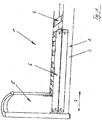
- Fig. 1 can be seen in a purely schematic representation of an example of a bed 1 according to the invention. This has in a conventional manner via a bed frame 2, which has two frames 3 in the illustrated embodiment, which extend between two BettPSuptern 5, of which the better overview because of only one in Fig. 1 is shown.
- the bed frame 2 serves to receive a lying surface element 4, which is a slatted frame in the illustrated embodiment. This in turn serves to receive a mattress or a cushion element not shown in the figures.
- bed 1 has a side rail 6, which extends over at least 50% of the extension of the bed frame 2 in the longitudinal direction 7.
- a side rail 6 is shown.
- each bed longitudinal side is equipped with a corresponding side rails 6.
- the side rail 6 can be transferred from a position of use to a non-use position and vice versa. In the position of use of the side rail 6 it serves as fall protection for a person lying in bed. In the non-use position of the side rail 6 - as in Fig. 1 is shown - is an unhindered entry to bed 1 allowed.
- Fig. 2 can be seen in a side view of the side rails 6 according to the invention in the position of use.
- the side rail 6 has two longitudinal beams arranged one above the other in the height direction 8, specifically via an upper longitudinal spar 9 and a lower longitudinal spar 10.
- the longitudinal bars 9, 10 are movable in the height direction 8, so that the side rails 6 are made the in Fig. 2 shown use position in the in Fig. 1 shown non-use position and vice versa is feasible.
- the lower longitudinal spar 10 is formed telescopic. It has two sections 11 and 12, which can be moved relative to each other according to the principle of corresponding tubes. In the exemplary embodiment shown, the first section 11 receives the second section 12 so as to be longitudinally displaceable.
- the side rail 6 further has two first articulated arms 14 and two second articulated arms 15.
- the pivot points 17 and 18 of the first and second articulated arm are each arranged at a distance from one another.
- the first articulated arms 14 are in turn each other end pivotally mounted on the other, that is arranged on the upper longitudinal spar 9, to form a respective pivot point sixteenth
- the second articulated arms 15 in turn are each pivotally hinged to a support beam 22 at the other end, with the respective formation of a pivot point 19.
- the lower longitudinal spar 10 is equipped in each case with two articulated arms 14 and 15 arranged rotatably thereon, the respective associated pivot points 17 and 18 being arranged at a distance from one another in the vertical direction 8.
- This spaced arrangement of the pivot points 17 and 18 ensures a coaxial guidance of the sections 11 and 12 of the lower longitudinal spar 10 so that it is not in the intended use in a transfer of the side rail 6 from the use position to the non-use position and vice versa to a canting of the two Sections 11 and 12 to each other.
- the articulated arms 14 and 15 carry on its opposite end face of the other articulated arm a tooth contour 27. These tooth contours 27 engage with each other, so that the articulated arms 14 and 15 of Gelenkarmcrus are interlocked. This leads to a positive guidance of the articulated arms 14 and 15 of a Gelenkarmcrus, to the effect that the articulated arms 14 and 15 always rotate at the same angle in a movement of the side rail 6.
- the articulated arms 14 and 15 of a Gelenkarmcrus are so far motion-synchronized.
- the upper longitudinal spar 9 is formed in a U-shaped cross-section, with the open side facing the lower longitudinal spar 10.
- the volume space 20 provided by the upper longitudinal spar 9 serves, in the non-use position of the side rail, to receive the first articulated arms 14 and sections of the lower longitudinal beam 10.
- a support beam 22 shown in the Embodiment is designed as a flat material, as this particular Fig. 3 lets recognize.
- the support beam 22 provides each end bearing 24 available, which serve to form the pivot points 19 of the articulated arrangement of the second articulated arms.
- the front side of the support beam 22 is equipped with an aperture 23 with the interposition of the second articulated arms 15.
- the support beam 22 and the diaphragm 23 form a volume space 25 between them, in the non-use position of the side rail 6, the second articulated arms 15 dip, as well as the lower longitudinal spar 10 at least in sections, as can be seen from the illustration Fig. 6 results.
- Fig. 6 The representation after Fig. 6 can further be found that in the non-use position of the side rail 6, the upper longitudinal spar 9 rests on the support beam 22 and provided by the support beam 22 bearing points 24, and this substantially gap-free, wherein the volume spaces 20 and 25, the articulated arms 14 and 15 and the lower longitudinal beam 10 completely record.
- the articulated arms and the longitudinal beam 10 are accommodated in the manner of a cassette arrangement, which is why the side rails 6 according to the invention can also be referred to as a cassette side grid.
- the telescopically formed longitudinal beam 10 is equipped with a force accumulator in the form of a tension spring 28. This ensures at a transfer of the side rail 6 from the non-use position into the position of use that a moving apart of the sections 11 and 12 of the longitudinal spar 10 is supported.
- a lever 29 formed on the inside of the second section 12 is provided, which cooperates with a driver 30 mounted at the end of the spring 28.
- the spring 28 In non-use position of the side rail 6, the spring 28 is in a stretched state. If the upper side rail 9 is then grasped on the user side and brought upwards in the height direction 8, then the side rail 6 folds out, as a result of which the lower longitudinal rail 10 is telescoped out. Shortly before reaching the position of use of the driver 30 snaps the end of the lever 29 and causes a spring force induced further movement of the second portion 12 relative to the first section 11, resulting in a transfer of the side rail 6 in the use position in which the articulated arms 14 each at the respective Abut stop 26 of the upper spar 9. In this position of the first section 11 and second section 12 locks the spring button trained locking device 13, as is made Fig. 2 is apparent. In this position, a back process of the side rail 6 in the non-use position can not take place without user-side actuation of the latching device 13.
- the latching device 13 If the latching device 13 is now actuated on the user side, then a movement movement of the first section 11 and the second section 12 is possible, that is to say the side rail 6 can be transferred from the use position into the non-use position.
- the spring 28 In this transfer of the side rail 6 in the non-use position, the spring 28 is tensioned, with reaching the spring position, as in Fig. 6 is shown, the lever 29 is disengaged with tensioned spring 28 from the driver 30 and then in the in Fig. 6 shown position is spent.
- a connection profile 33 is used to connect the side rail 6 to a frame 3 of a bed frame 2. This has an inner contour which is formed corresponding to the outer contour of the frame 3.
- the support beam 22 is screwed to this connection profile 33, for which purpose a in Fig. 7 shown bolt 21 is used.
- the connecting profile 33 is applied to the arrangement on the frame 3 with its upper profile section to the frame 3 and then pivoted clockwise until it rests against the entire surface of the frame 3. Then the grub screw 34 is screwed into the provided by the frame 3 channel 35 for fixing the position.
- the connecting profile 33 together with side rails 6 arranged thereon is now permanently and reliably mounted on the frame 3.
- the support beam 22 may be screwed by means of corresponding bolts 21 directly to the frame 3.
- the frame 3 is to be equipped with a corresponding bore through which the pin 21 engages in the final assembled state. Since in the illustrated embodiment, the frame 3 has a curved surface 32 formed, for the purpose of position-safe arrangement of the supporting beam 22 on the frame 3, an adapter element 31 is provided, the frame side has a corresponding to the surface 32 of the frame 3 contour.
- an arrangement of the side rail 6 is not on the frame 3 of the bed frame 2, but on a profile body 36 of the lying surface element 4, that is, for example, a slatted frame.
- a correspondingly formed carrier beam 22 is used, which overlaps the frame 3 on the upper side.
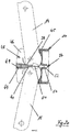
- FIGS. 10 to 21 show a preferred embodiment of the invention, instead of a locking device 13 has locking elements 37 and 38, which locking elements 37 and 38 in the locked position ensure that the side rails 6 is not unintentionally pivoted from its use position to its non-use position.
- each pair of articulated arms a locking elements 37 and 38 is provided, which can be operated on the user side by means of a corresponding handle 43 and from its locked position into the non-locking position.
- the sectional view after FIG. 14 shows the first blocking element 37 and the second blocking element 38, it being apparent from this representation that the first blocking element 37 cooperates with the articulated arms 14 and 15, which are arranged on one end of the telescoping longitudinal spar 10.
- the second locking element 38 interacts with the articulated arms 14 and 15, which are arranged on the other side of the telescoping longitudinal spar 10.
- the articulated arms 14 and 15 each have locking element side via a projection 39 and 40.
- These projections 39 and 40 cooperate in the blocking position with the associated locking element 37 and 38 together, as shown in particular the illustration FIG. 14 lets recognize.
- the respective extensions 39 and 40 abut the respective blocking element 37 and 38, respectively, and are based on this.
- the projections 39 and 40 act as an abutment, so clamp in the blocking position the respective associated locking element 37 and 38 between them, as a result of a rotatability of the articulated arms 14 and 15 is prevented with the result that the side rails 6 not from the example in the Figures 10 and 14 shown use position in the example in FIG. 16 shown non-use position can be transferred.
- the locking elements 37 and 38 are translationally movable in the longitudinal direction 7, which allows the user side, the locking elements 37 and 38 to proceed accordingly.
- the locking element 37 for transfer to the non-locking position with respect to the plane of the drawing FIG. 14 to move to the left and the second blocking element 38 to the right.
- the blocking elements 37 and 38 are coupled to a respective handle 43 which is accessible from the outside on the user side, as can be seen for example from a synopsis of Figures 10 . 14 and 19 results.
- FIG. 16 can in this context, the non-use position of the side rail 6 and thus located in non-locking position locking elements 37 and 38 recognize.
- the blocking element 37 or 38 has - as in particular the illustration after FIG. 20
- This locking body 49 serves the actual VerFblockade the articulated arms 14 and 15 and is in the blocking case in the manner already described at the provided by the articulated arms 14 and 15 extensions 39 and 40 at.
- the locking body 49 and thus also the blocking element 37 is guided by means of a holm thesisen bearing 44, so that the locking element 37 keeps its track in Verfahrfall and not tilted in its relative position relative to the articulated arms 14 and 15.
- the blocking element 37 furthermore has a spring receptacle 50, which receives a spring 52 in the final assembled state, by means of which spring 52 the blocking element 37 is prestressed relative to the articulated arms 14 and 15.
- the spring 52 By means of the spring 52, the blocking element 37 is under a force bias, which causes the locking element 37 is always anxious, according to its blocking position FIG. 20 to proceed.
- the spring retainer 50 and the locking body 49 are coupled to each other via a connecting portion 51 which surrounds the pivot-point-side portions of the articulated arms 14 and 15 in the manner of a frame, as can be seen in particular from the sectional view FIG. 19 results.
- the user side is first by means of the corresponding handle 43, the locking element 37 and the locking element 38 out of engagement with the projections 39 and 40 of the articulated arms 14 and 15 to bring, so that a Twisting movement of the articulated arms 14 and 15 can take place.
- an articulated arm 48 is used, which adjoins the spar body 45 of the longitudinal spar 10, as can be seen in particular from a synopsis of Figures 18 . 20 and 21 results.
- the joint receptacle 48 has two plates 46 and 47 which receive in the final assembled state, the articulated arms 14 and 15 mosverschwenklich between them.
- the joint receptacle 48 further serves the arrangement of the handle 43, which is in operative connection with the associated locking element 37 and 38, as shown in particular the sectional view FIG. 19 lets recognize.
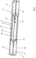
- the telescopic longitudinal spar 10 provides a volume space 56.
- This volume space 56 serves to receive an electromotive drive device 53, which interacts with the two spar sections 11 and 12.
- the electromotive drive device 53 ensures that the spar sections 11 and 12 move in the direction of displacement or longitudinal direction 7 relative to each other, that is diverge when transferred to the use position or moved into each other in a transfer to the non-use position.
- the drive device 53 has a threaded rod 55. This is one end defined by means of a holder 57 relative to the spar section 11, by means of a Vermosschutzes 58, so that a relative movement between the threaded rod 55 on the one hand and spar section 11 on the other hand is not allowed.
- the threaded rod 55 carries a threaded part 60 carried by a holder 59.
- the threaded part 60 is able to rotate about the axis of rotation 61 in the direction of the arrow 62, permitting relative rotatability of the threaded part 60 relative to the spar section 12. A movement of the threaded part 60 in the longitudinal direction 7 relative to the spar portion 12 is not possible due to the inclusion of the threaded portion 60 of the holder 59.
- the drive device 53 further has a motor 54. This is used in the figures not shown drive the threaded portion 60, wherein a drive of the threaded portion 60 in both clockwise and in the opposite direction is possible, as symbolized by the arrow 62.
- the motor 54 is turned on by a user, preferably by means of radio remote control.
- the motor 54 then drives the threaded portion 60, resulting in that the threaded rod 55 in the longitudinal direction 7 moves relative to the threaded portion 60. Since the threaded rod 55 is fixed at one end to the spar section 11, as a result of this traversing movement of the threaded rod 55, a displacement of the spar section 11 relative to the spar section 12 is effected.
- the Hofmabête 11 and 12 proceed depending on the direction of rotation of the threaded portion 60 either towards each other or apart.
- a transfer of the side rail 6 can be achieved in the use position or in the non-use position.
- the telescopically formed longitudinal spar 10 may be equipped with a force accumulator in the form of a tension spring 28, as already with reference to FIG Fig. 6 described.
- a force accumulator in the form of a tension spring 28, as already with reference to FIG Fig. 6 described.
- ⁇ U> REFERENCE LIST ⁇ / u> 1 bed 18 pivot point 2 bed frame 19 pivot point 3 frame 20 volume space 4 Lying surface element 21 bolt 5 headboard 22 spar 6 side rails 23 cover 7 longitudinal direction 24 depository 8th height direction 25 volume space 9 upper longitudinal spar 26 attack 10 lower longitudinal spar 27 tooth contour 11 first section 28 feather 12 second part 29 lever 13 locking device 30 takeaway 14 first articulated arm 31 adapter element 15 second articulated arm 32 surface 16 pivot point 33 connection profile 17 pivot point 34 grub screw 35 channel 56 Volumersraum 36 profile body 57 holder 37 first blocking element 58 twist protection 38 second blocking element 59 holder 39 head Start 60 threaded part 40 head Start 61 axis of rotation 41 displacement direction 62 arrow 42 compression spring 43 handle 44 camp
Abstract
Die Erfindung betrifft ein Bett, insbesondere Kranken- und/oder Pflegebett, mit einem Seitengitter (6), das zwei höhenverstellbare Längsholme (9, 10) aufweist, die aus einer Gebrauchsstellung in eine Nicht-Gebrauchsstellung und umgekehrt überführbar sind, wobei der in Gebrauchsstellung untere der beiden Längsholme (9, 10) teleskopierbar ausgebildet ist, wobei an dem teleskopierbaren Längsholm (10) einendseitig sowie anderendseitig jeweils ein erster und ein zweiter Gelenkarm (14, 15) jeweils verschwenkbar angeordnet sind, wobei die Drehpunkte (17, 18) von erstem und zweitem Gelenkarm (14, 15) jeweils zueinander beabstandet ausgebildet sind, wobei die ersten Gelenkarme (14) anderendseitig jeweils verschwenkbar am anderen Längsholm (9) und die zweiten Gelenkarme (15) anderendseitig jeweils verschwenkbar an einem Tragholm (22) angeordnet sind.

Description
Die Erfindung betrifft ein Bett, insbesondere ein Kranken- und/oder Pflegebett, mit einem Seitengitter, das zwei höhenverstellbare Längsholme aufweist, die aus einer Gebrauchsstellung in eine Nicht-Gebrauchsstellung und umgekehrt überführbar sind, wobei der in Gebrauchsstellung untere der beiden Längsholme teleskopierbar ist.The invention relates to a bed, in particular a hospital and / or nursing bed, with a side rail having two height-adjustable longitudinal bars, which are convertible from a use position to a non-use position and vice versa, wherein the lower position in the use position of the two longitudinal bars is telescopic.
Betten im Allgemeinen sowie Kranken- und/oder Pflegebetten im Speziellen sind aus dem Stand der Technik an sich gut bekannt, weshalb es eines gesonderten druckschriftlichen Nachweises an dieser Steife nicht bedarf. Es sei deshalb nur beispielhaft auf die
Ein gattungsgemäßes Bett verfügt über ein Seitengitter, vorzugsweise zwei Seitengitter, wobei jeder Längsseite des Bettes ein Seitengitter zugeordnet ist. Der Sinn und Zweck eines Seitengitters besteht in erster Linie darin, eine im Bett liegende Person vor einem unbeabsichtigten Herausfallen aus dem Bett zu schützen. Seitengitter dienen insofern der Sicherheit einer im Bett liegenden Person. In der Regel finden Seitengitter im Krankenhaus- und/oder Pflegebereich bei Kranken- und/oder Pflegebetten Verwendung.A generic bed has a side rail, preferably two side rails, each longitudinal side of the bed is associated with a side rail. The purpose of a side rail is primarily to protect a person lying in bed from accidentally falling out of bed. Side rails serve as far as the safety of a person lying in bed. As a rule, side rails in the hospital and / or nursing area are used for hospital and / or nursing beds.
Seitengitter können in aller Regel aus einer Gebrauchsstellung in eine Nicht-Gebrauchsstellung und umgekehrt überführt werden. In der Nicht-Gebrauchsstellung des Seitengitters ist der Betteinstieg ermöglicht. Die vorerläuterte Schutzwirkung ergibt sich in der Gebrauchsstellung des Seitengitters.Side rails can usually be transferred from a use position to a non-use position and vice versa. In the non-use position of the side rail, it is possible to board. The vorerläuterte protective effect results in the use position of the side rail.
Die aus der
Obgleich sich die vorbekannte Konstruktion im alltäglichen Praxiseinsatz bewährt hat, ist sie nicht frei von Nachteilen. So baut die vorbekannte Seitengitterkonstruktion auch in Nicht-Gebrauchsstellung das Seitengitter vergleichsweise hoch auf, was bei der Verwendung von entsprechend dünn ausgebildeten Matratzen einem ungehinderten Einstieg ins Bett entgegenstehen kann. Von Nachteil ist ferner, dass die zur einendseitigen Abstützung der Längsholme vorgesehenen Tragpfosten aufgrund ihrer Teleskopierbarkeit konstruktionsbedingt über die untere Randkante des Zargenprofils des Bettgestells hinaus vorstehen, was die Höhenverfahrbarkeit des Bettgestells nach unten begrenzt.Although the previously known construction has proven itself in everyday practice, is they are not free from disadvantages. Thus, the prior art side rail construction also builds in non-use position, the side rails comparatively high, which may conflict with the use of appropriately thin mattresses an unhindered entry into bed. A further disadvantage is that the one-sided support of the longitudinal beams provided support post project due to their telescoping design beyond the lower edge of the frame profile of the bed frame, which limits the Höhenverfahrbarkeit the bed frame down.
Aus dem Stand der Technik ist gemäß der
Die
Aus der
Die
Ausgehend vom vorbeschriebenen Stand der Technik ist es die Aufgabe der Erfindung, eine neuartige Seitengitterkonstruktion vorzuschlagen, die möglichst platzsparend ausfällt und darüber hinaus das Bettgestell in seiner Möglichkeit nicht beschränkt, in Höhenrichtung nach unten verfahren werden zu können.Starting from the above-described prior art, it is the object of the invention to propose a novel side rail construction that fails as possible to save space and beyond the bed frame is not limited in its ability to be moved in the height direction down.
Zur Lösung dieser Aufgabe wird mit der Erfindung ein Bett der gattungsgemäßen Art vorgeschlagen, das sich dadurch auszeichnet, dass an dem teleskopierbaren Längsholm einendseitig sowie anderendseitig jeweils ein erster und ein zweiter Gelenkarm jeweils verschwenkbar angeordnet sind, wobei die Drehpunkte von erstem und zweitem Gelenkarm jeweils zueinander beabstandet ausgebildet sind, wobei die ersten Gelenkarme anderendseitig jeweils verschwenkbar am anderen Längsholm und die zweiten Gelenkarme anderendseitig jeweils verschwenkbar an einem Tragholm angeordnet sind.To solve this problem, a bed of the generic type is proposed with the invention, which is characterized in that on the telescoping longitudinal spar einendseitig and the other end each have a first and a second articulated arm are each pivotally mounted, wherein the pivot points of the first and second articulated arm to each other are formed spaced apart, wherein the first articulated arms at the other end are each pivotally mounted on the other longitudinal spar and the second articulated arms at the other end are each arranged pivotably on a support beam.
Das erfindungsgemäße Seitengitter kann ziehharmonikagleich aus der Gebrauchsstellung in die Nicht-Gebrauchsstellung verschwenkt werden, so dass es in Nicht-Gebrauchsstellung eine nur denkbar kompakte Baugröße einnimmt. Dabei baut das Seitengitter in Nicht-Gebrauchsstellung in Höhenrichtung so wenig auf, dass selbst im Falle der Verwendung vergleichsweise dünner Bettmatratzen ein Überragen der von der Bettmatratze bereitgestellten Liegefläche durch das Seitengitter unterbleibt. Damit ist auch bei vergleichsweise dünnen Matratzen ein Einstieg ins Bett bei einem sich nicht in Gebrauchsstellung befindlichen Seitengitter nicht behindert.The side rails according to the invention can be accordion-like pivoted from the use position to the non-use position, so that it occupies a non-use position a very compact size. In this case, the side rails in non-use position in the vertical direction so little on that even in the case of using comparatively thin bed mattresses, a projecting beyond the bed mattress provided by the bed surface is omitted by the side rails. This is not a hindrance to bed in a not in use position located side rails even with comparatively thin mattresses.
Von Vorteil der erfindungsgemäßen Ausgestaltung ist zudem, dass das Seitengitter nicht über die untere Randkante des Zargenprofils des Bettgestells nach unten hin vorsteht, was es gestattet, das erfindungsgemäße Seitengitter in Kombination mit sogenannten Ultraniedrigbetten zu verwenden, das heißt mit Betten, deren Bettgestell bis zur Auflage auf dem Untergrund nach unten verfahren werden kann. Mit aus dem Stand der Technik vorbekannten Seitengittern ist dies nicht möglich.An advantage of the embodiment of the invention is also that the side rail does not project beyond the lower edge of the frame profile of the bed frame down, which allows the side rails according to the invention in combination with so-called ultra-low beds to use, that is, with beds, the bed frame to rest can be moved down to the ground. With previously known from the prior art side rails this is not possible.
Das erfindungsgemäße Seitengitter verfügt über einen in Gebrauchsstellung des Seitengitters oberen Holm einerseits sowie einen unteren Holm andererseits. Diese beiden Holme sind mittels erster Gelenkarme gekoppelt, wobei diese ersten Gelenkarme jeweils einendseitig sowie anderendseitig am jeweiligen Längsholm verdrehbar angeordnet sind. In Kombination mit der Teleskopierbarkeit des unteren Längsholms ergibt diese Anordnung eine relative Verschiebbarkeit von oberem zu unterem Längsholm in Höhenrichtung.The side rails according to the invention has a in the use position of the side rail upper rail on the one hand and a lower rail on the other. These two spars are coupled by means of first articulated arms, wherein these first articulated arms are arranged in each case one end side and the other end rotatable on the respective longitudinal spar. In combination with the telescoping of the lower longitudinal beam, this arrangement gives a relative displacement of upper to lower longitudinal spar in the height direction.
Es sind ferner zwei zweite Gelenkarme vorgesehen. Diese sind jeweils einendseitig wie anderendseitig verschwenkbar am unteren Längsholm sowie an einem Tragholm angeordnet. Dies bewirkt in Kombination mit der Teleskopierbarkeit des unteren Längsholms eine Verstellmöglichkeit des unteren Längsholms relativ zum Tragholm in Höhenrichtung, und damit auch eine Verschieblichkeit des oberen Längsholms relativ zum Tragholm in Höhenrichtung.There are also provided two second articulated arms. These are each one end side as the other end pivotally mounted on the lower longitudinal spar and arranged on a support beam. This causes in combination with the telescoping of the lower longitudinal beam an adjustment of the lower longitudinal spar relative to the spar in the height direction, and thus a displaceability of the upper longitudinal spar relative to the spar in the height direction.
Der untere Längsholm des Seitengitters trägt mithin einendseitig wie anderendseitig verschwenkbar daran angeordnet erste und zweite Gelenkarme. Dabei ist erfindungsgemäß vorgesehen, dass die jeweiligen Drehpunkte von erstem und zweitem Gelenkarm beabstandet zueinander angeordnet sind. Die am unteren Längsholm angeordneten Gelenkarme bilden mithin nicht einen gemeinsamen Drehpunkt aus. Diese Ausgestaltung stellt in vorteilhafter Weise sicher, dass es bei einer Verfahrbewegung des oberen und/oder des unteren Längsholms in Höhenrichtung, das heißt bei einer Überführung des Seitengitters aus der Nicht-Gebrauchsstellung in die Gebrauchsstellung und umgekehrt nicht zu einem Verkanten der die Teleskopierbarkeit besorgenden Holmabschnitte kommt. Diese "Doppel-Drehpunkt"-Ausgestaltung stellt also sicher, dass die miteinander kommunizierenden Abschnitte des teleskopierbaren Längsholms stets koaxial zueinander geführt werden. Dabei fahren die Holmabschnitte ineinander, wenn das Seitengitter in seine Nicht-Gebrauchsstellung verbracht wird, wohingegen sie auseinanderfahren, wenn das Seitengitter in seine Gebrauchsstellung überführt wird.The lower longitudinal spar of the side rail therefore carries at one end as the other end side pivotally mounted thereon arranged first and second articulated arms. In this case, it is provided according to the invention that the respective pivot points of the first and second articulated arm are arranged at a distance from one another. The arranged on the lower longitudinal beam articulated arms therefore do not form a common pivot point. This configuration ensures advantageously that it is not at a displacement of the upper and / or the lower longitudinal spar in the height direction, ie at a transfer of the side grid from the non-use position to the use position and vice versa to tilting the telescoping soliciting Holmabschnitte comes. This "double pivot" design thus ensures that the communicating sections of the telescoping longitudinal spar are always guided coaxially to each other. The spar sections ride into each other when the side rail is moved to its non-use position, whereas they move apart when the side rail is transferred to its position of use.
Die vorbeschriebene Konstruktion ermöglicht es im Ergebnis, dass bei einer Überführung des Seitengitters aus der Gebrauchsstellung in die Nicht-Gebrauchsstellung die beiden Längsholme in Höhenrichtung nach unten verfahren, wobei die Gelenkarme aufgrund der Teleskopierbarkeit des unteren Längsholms einschwenken können. Dies erbringt in der Nicht-Gebrauchsstellung eine äußerst kompakte und wenig ausladende Anordnung, die im Unterschied zu herkömmlichen Seitengittern sehr viel platzsparender ist.The above-described construction makes it possible as a result that when transferring the side rail from the use position to the non-use position, the two longitudinal beams move down in the height direction, wherein the articulated arms can swing in due to the telescoping of the lower longitudinal spar. This provides in the non-use position an extremely compact and less bulky arrangement, which is much more space-saving in contrast to conventional side rails.
Der in Gebrauchsstellung obere der beiden Längsholme stellt gemäß einem weiteren Merkmal der Erfindung einen zum unteren Längsholm hin offenen Volumenraum bereit. In diesen Volumenraum können bei Überführung des Seitengitters aus der Gebrauchsstellung in die Nicht-Gebrauchsstellung die ersten Gelenkarme sowie der zweite, das heißt untere Längsholm zumindest abschnittsweise eintauchen. Dies erbringt eine noch weiter verbesserte platzsparende Anordnung in Nicht-Gebrauchsstellung. Zwecks Ausbildung des erfindungsgemäßen Volumenraums ist vorgesehen, dass der in Höhenrichtung obere Längsholm im Querschnitt vorzugsweise U-förmig ausgebildet ist.The upper position of the two longitudinal members in the position of use provides, according to a further feature of the invention, a volume space open towards the lower longitudinal member. In this volume space when transferring the side rail from the use position in the non-use position, the first articulated arms and the second, that is, lower longitudinal beam at least partially submerge. This provides a further improved space-saving arrangement in non-use position. For the purpose of forming the volume space according to the invention, it is provided that the upper longitudinal beam, which is upper in the vertical direction, is preferably U-shaped in cross-section.
Gemäß einem weiteren Merkmal der Erfindung ist vorgesehen, dass der Tragholm als separates Bauteil ausgebildet ist, das zur verschwenkbaren Anordnung der zweiten Gelenkarme jeweilige Lagerstellen bereitstellt.According to a further feature of the invention, it is provided that the carrier beam is formed as a separate component, which provides for the pivotable arrangement of the second articulated arms respective bearing points.
Die Ausgestaltung des Tragholms als separates Bauteil ist insbesondere aus Montagegründen von Vorteil. So kann das Seitengitter tragholmseitig in einfacher Weise am Bett angeordnet werden, beispielsweise durch Verschrauben. Dabei kann je nach gewünschter Ausgestaltung das Seitengitter entweder an einem Bettrahmen des Bettes oder an einem vom Bettrahmen aufgenommenen Liegeflächenelement, wie zum Beispiel einem Lattenrost montiert werden, wobei die Anordnung des Seitengitters an einem Liegeflächenelement den Vorteil mit sich bringt, dass es zusammen mit dem Liegeflächenelement verschwenkbar ist. Der Tragholm kann in einfacher Weise als Flachmaterial ausgebildet sein, der einendseitig wie anderendseitig entweder Lagerbolzen für die Gelenkarme aufweist oder über Bohrungen verfügt, in die entsprechende Gelenkbolzen einzusetzen sind. Bevorzugterweise können in Bohrungen einzusetzende Gelenkbolzen gleichermaßen für eine Anordnung des Tragholms am Bettrahmen oder am Liegeflächenelement dienen.The design of the support beam as a separate component is particularly for assembly reasons of advantage. Thus, the side rails Tragholmseitig be easily arranged on the bed, for example by screwing. Depending on the desired configuration, the side rails can be mounted either on a bed frame of the bed or on a lying surface element received by the bed frame, such as a slatted frame, whereby the arrangement of the side grid on a lying surface element brings with it the advantage that it together with the lying surface element is pivotable. The support beam can be formed in a simple manner as a flat material, which has one end side as the other end either bearing pin for the articulated arms or has holes to be inserted into the corresponding hinge pin. Preferably, hinge pins to be used in bores can equally serve for arranging the support beam on the bed frame or on the lying surface element.
Alternativ zur vorbeschriebenen Ausgestaltung kann vorgesehen sein, dass die Gelenkarme direkt am Bett, das heißt am Bettrahmen oder am Liegeflächenelement angeordnet sind. In diesem Fall ist der Tragholm als integraler Bestandteil eines vom Bett bereitgestellten Bettrahmens oder Liegeflächenelements ausgebildet.As an alternative to the above-described embodiment, it can be provided that the articulated arms are arranged directly on the bed, that is to say on the bed frame or on the lying surface element. In this case, the support beam is formed as an integral part of a provided by the bed bed frame or lying surface element.
Es ist gemäß einem weiteren Merkmal der Erfindung vorgesehen, dass die einendseitig bzw. anderendseitig des teleskopierbaren Längsholms jeweils angeordneten Gelenkarme hinsichtlich ihrer relativen Lage zueinander zwangsgeführt ausgebildet sind. Diese Zwangsführung bewirkt, dass die einendseitig bzw. anderendseitig jeweils am Längsholm angeordneten Gelenkarme stets den gleichen Winkel zum Längsholm einschließen. Es wird so in vorteilhafter Weise eine ungleichmäßige Abstandsführung vermieden. Durch die erfindungsgemäß vorgesehene Zwangsführung sind die einander zugeordneten Gelenkarme in ihrer Bewegung synchronisiert, so dass sie im Betätigungsfall stets in identischer Weise ein- bzw. ausschwenken.It is provided according to a further feature of the invention that the one-sided or the other end of the telescopic longitudinal spar respectively arranged articulated arms are formed positively guided with respect to their relative position to each other. This forced operation causes the one-sided or the other end side respectively arranged on the longitudinal beam articulated arms always include the same angle to the longitudinal beam. It is thus advantageously avoided a non-uniform spacing guide. By inventively provided forced operation are the mutually associated Articulated arms synchronized in their movement, so that they always swing in the actuation case in an identical manner or swing.
Die Bewegungssynchronisation kann gemäß einem weiteren Merkmal der Erfindung dadurch erreicht werden, dass die einander zugeordneten Gelenkarme eine ineinandergreifende Verzahnung aufweisen. Zu diesem Zweck verfügt jeder Gelenkarm über eine dem anderen Gelenkarm zugeordnete Zahnkontur, welche Zahnkonturen im endmontierten Zustand des Seitengitters ineinandergreifen, wodurch die Zwangsführung gegeben ist.The movement synchronization can be achieved according to a further feature of the invention in that the mutually associated articulated arms have an interlocking toothing. For this purpose, each articulated arm has a tooth contour assigned to the other articulated arm, which tooth contours intermesh in the final mounted state of the side rail, whereby the positive guidance is given.
Es ist gemäß einem weiteren Merkmal der Erfindung vorgesehen, dass der teleskopierbare Längsholm zwei Abschnitte aufweist, die unter Zwischenordnung eines Kraftspeichers relativ zueinander verfahrbar angeordnet sind. Als ein solcher Kraftspeicher kommt insbesondere eine Schraubenfeder zum Einsatz.It is provided according to a further feature of the invention that the telescoping longitudinal spar has two sections, which are arranged movable relative to each other with the interposition of an energy store. As such an energy storage, in particular, a coil spring is used.
Der Kraftspeicher wirkt auf die beiden Gelenkarme ein, und zwar derart, dass bei einer Überführung des Seitengitters aus der Nicht-Gebrauchsstellung in die Gebrauchsstellung ein Auseinanderfahren der Abschnitte des teleskopierbaren Rohres und damit ein Verschwenken der Gelenkarme in die für die Gebrauchsstellung des Seitengitters einzunehmende Position unterstützt wird.The energy storage acts on the two articulated arms, in such a way that when transferring the side rail from the non-use position into the use position, a moving apart of the sections of the telescoping tube and thus pivoting of the articulated arms supported in the position to be taken for the use of the side rail position becomes.
Der Kraftspeicher ist bevorzugterweise für einen Verwender unsichtbar innerhalb eines von dem teleskopierbaren Längsholm bereitgestellten Hohlraum angeordnet. Der vorzugsweise als Feder ausgebildete Kraftspeicher wird bei einer Überführung des Seitengitters aus der Gebrauchsstellung in die Nicht-Gebrauchsstellung gespannt. Eine Federspannung erfolgt mithin unter Einwirkung der auf das Seitengitter im Überführungsfall unterstützend einwirkenden Gewichtskraft. Zu diesem Zweck ist innenseitig des teleskopierbaren Längsholms ein Mitnehmer positioniert, der bei einer Überführung des Seitengitters in die Nicht-Gebrauchsstellung die als Kraftspeicher dienende Feder mitnimmt und spannt. Wird im Fall der Überführung des Seitengitters in die Gebrauchsstellung selbiges angehoben, so verschwenken die Gelenkarme in schon vorbeschriebener Weise. Dabei entspannt sich die als Kraftspeicher dienende Feder im letzten Moment der Verschwenkbewegung, wodurch das Auseinanderfahren des teleskopierbaren Längsholms und damit das Verschwenken der Gelenkarme bis in die endgültige Gebrauchsstellung federinduziert unterstützt wird. In vorteilhafter Weise ist so eine ansonsten notwendige Zweihandhabung vermieden.The energy store is preferably arranged invisibly within a cavity provided by the telescoping longitudinal spar for a user. The preferably designed as a spring energy storage is stretched at a transfer of the side rail from the use position in the non-use position. A spring tension is thus under the action of the force acting on the side rails in the transfer case weight force. For this purpose, a driver is positioned on the inside of the telescoping longitudinal spar, which entrains and spans the spring serving as a force storage in a transfer of the side rail in the non-use position. If, in the case of transferring the side rail into the use position, the same is raised, the articulated arms pivot in the manner already described. In this case, the serving as a force storage spring relaxes at the last moment of the pivoting movement, whereby the divergence of the telescopic longitudinal spar and thus the pivoting of the articulated arms is spring-assisted to the final position of use. Advantageously, it is so avoided an otherwise necessary two-handed operation.
Mit Erreichen der endgültigen Gebrauchsstellung verrasten die beiden Abschnitte des teleskopierbaren Längsholms, so dass sie in ihrer relativen Lage gesichert sind. Ein unbeabsichtigtes Überführen des Seitengitters aus der Gebrauchsstellung in die Nicht-Gebrauchsstellung ist damit unterbunden. Um eine solche Verfahrbewegung bewerkstelligen zu können, ist es zunächst erforderlich, die Rasteinrichtung zu lösen. Dies geschieht verwenderseitig beispielsweise mittels Tastendruck.Upon reaching the final position of use lock the two sections of the telescopic longitudinal spar, so that they are secured in their relative position. An unintentional transfer of the side rail from the position of use in the non-use position is thus prevented. In order to accomplish such a movement movement, it is first necessary to release the locking device. This happens on the user side, for example, by pressing a button.
Es ist gemäß einem weiteren Merkmal der Erfindung vorgesehen, dass die ersten und/oder die zweiten Gelenkarme kraftgekoppelt sind. Dies kann beispielsweise durch einen die einzelnen Gelenkarme kraftkoppelnden Seilzug realisiert werden. In vorteilhafter Weise erbringt diese Ausgestaltung eine Bewegungssynchronisation der beiden Gelenkarmpaare, womit eine stets parallele Ausrichtung von oberem und unterem Holm gewährleistet ist. Diese Ausgestaltung ist allerdings rein optional, da es für eine bestimmungsgemäße Funktion des erfindungsgemäßen Seitengitters nicht erforderlich ist, die Längsholme parallel zu führen.It is provided according to a further feature of the invention that the first and / or the second articulated arms are force-coupled. This can be realized, for example, by a force coupling the individual articulated arms cable. Advantageously, this embodiment provides a movement synchronization of the two Gelenkarmpaare, whereby an always parallel alignment of the upper and lower spar is ensured. However, this embodiment is purely optional, since it is not necessary for a proper function of the side rails according to the invention to guide the longitudinal beams parallel.
Gemäß einem besonderen Vorschlag der Erfindung ist vorgesehen, dass ein mit den einendseitig des teleskopierbaren Längsholms angeordneten Gelenkarmen zusammenwirkendes, erstes Sperrelement und ein mit den anderendseitig des telekopierbaren Längsholms angeordneten Gelenkarmen zusammenwirkende, zweites Sperrelement vorgesehen sind, wobei in Gebrauchsstellung des Seitengitters eine Verdrehbewegung der Gelenkarme mittels der Sperrelemente unterbunden ist.According to a particular proposal of the invention it is provided that a arranged with the one end of the telescopic longitudinal beam articulated arms cooperating, first locking element and arranged with the other end of the telekopierbaren longitudinal spar joint arms cooperating, second locking element are provided, wherein in the use position of the side rail, a rotational movement of the articulated arms means the locking elements is prevented.
Danach verfügt das Seitengitter über zwei Sperrelemente, nämlich ein erstes Sperrelement und ein zweites Sperrelement. Dabei wirkt das erste Sperrelement mit einem ersten Gelenkarmpaar, das heißt mit den einendseitig des teleskopierbaren Längsholms angeordneten Gelenkarmen und das zweite Sperrelement mit einem zweiten Gelenkarmpaar, das heißt den anderendseitig des teleskopierbaren Längsholms angeordneten Gelenkarmen zusammen. Mittels dieser Sperrelemente sind die Gelenkarme in ihrer Verdrehbewegung blockiert, wenn sich das Seitengitter in Gebrauchsstellung befindet. Die erfindungsgemäß vorgesehenen Sperrelemente sorgen mithin dafür, dass in Gebrauchsstellung des Seitengitters eine Verdrehbewegung der Gelenkarme unterbunden, das heißt gesperrt ist.Thereafter, the side rail has two locking elements, namely a first locking element and a second locking element. In this case, the first locking element acts with a first Gelenkarmpaar, ie with the one end of the telescopic longitudinal beam arranged articulated arms and the second locking element with a second Gelenkarmpaar, that is the other end of the telescoping longitudinal spar arranged articulated arms together. By means of these locking elements, the articulated arms are blocked in their twisting movement when the side rails are in the position of use. The inventively provided locking elements therefore ensure that prevented in the use position of the side rail a rotational movement of the articulated arms, that is locked.
Diese Ausgestaltung stellt mithin sicher, dass eine ungewollte Überführung des Seitengitters aus der Gebrauchsstellung in die Nicht-Gebrauchsstellung nicht möglich ist. Erst infolge eines verwenderseitigen Eingriffs können die Sperrelemente in ihre jeweilige Nicht-Sperrstellung überführt werden, was dann ein Verfahren des Seitengitters in die Nicht-Gebrauchsstellung gestattet. Solange sich die Sperrelemente in ihrer Sperrstellung befinden, ist ein Absenken des Seitengitters, das heißt eine Überführung desselben in die Nicht-Gebrauchsstellung unterbunden. Dies ist insbesondere aus sicherheitstechnischen Gründen von Vorteil, da sowohl eine unbeabsichtigte Fehlbedienung als auch ein sonstwie ungewolltes Überführen des Seitengitters in die Nicht-Gebrauchsstellung unterbunden ist, so dass insbesondere Quetsch-Verletzungen beim Verwender des Bettes und/oder des Seitengitters ausgeschlossen sind, wie sie entstehen können, wenn sich im Falle einer Seitengitter-Absenkung Körperteile des Verwenders zwischen den Holmen des Seitengitters befinden.This embodiment thus ensures that an unwanted transfer of the side rail from the use position to the non-use position is not possible. Only as a result of a user-side engagement, the locking elements can be converted into their respective non-locking position, which then allows a process of the side rail in the non-use position. As long as the locking elements are in their locked position, a lowering of the side rail, that is, a transfer of the same in the non-use position is suppressed. This is particularly advantageous for safety reasons, since both an unintentional incorrect operation and an otherwise unwanted transferring the side rail is prevented in the non-use position, so that in particular squeezing injuries in the user of the bed and / or side rails are excluded, as they can arise when in the case of a side rail subsidence body parts of the user between the bars of the side rail.
In Sperrstellung liegen die Sperrelemente an den jeweils zugehörigen Gelenkarmen an, so dass eine für eine Überführung des Seitengitters aus der Gebrauchsstellung in die Nicht-Gebrauchsstellung notwendige Verschwenkbewegung der Gelenkarme nicht stattfinden kann. Dabei liegen die Sperrelemente zwischen den jeweils zugehörigen Gelenkarmen an, so dass sich die Gelenkarme unter Zwischenordnung des jeweils zugehörigen Sperrelements gegeneinander abstützen, was die Verdrehbewegung der Gelenkarme sperrt. In konstruktiv einfacher Weise wird so die schon vorbeschriebene Sperrfunktion realisiert, wobei die erfindungsgemäße Ausgestaltung ob ihrer vergleichsweisen einfachen Konstruktion in der Anwendung zuverlässig und robust ist.In locking position, the locking elements abut against the respective associated articulated arms, so that a necessary for a transfer of the side rail from the use position in the non-use position pivoting movement of the articulated arms can not take place. In this case, the locking elements lie between the respective associated articulated arms, so that the articulated arms are supported against each other with the interposition of the respectively associated locking element, which blocks the rotational movement of the articulated arms. In a structurally simple manner as already described above blocking function is realized, the inventive design is reliable and robust whether their comparatively simple design in the application.
Die Gelenkarme weisen gemäß einem weiteren Merkmal der Erfindung Vorsprünge, das heißt Fortsätze auf, die mit den zugehörigen Sperrelementen zusammenwirken und an diesen in Sperrstellung anliegen. Die Gelenkarme stellen mithin Vorsprünge bereit, die ihrerseits mit dem zugehörigen Sperrelement zusammenwirken, wobei die Vorsprünge sperrelementseitig Anlageflächen bereitstellen, die in Sperrstellung des Sperrelementes am Sperrelement anliegen, womit die Verdrehbewegung der Gelenkarme blockiert ist. Die gelenkarmseitigen Vorsprünge nehmen in Sperrstellung das zugehörige Sperrelement mithin zwischen sich auf und stützten sich so gegenüber einander unter Zwischenordnung des Sperrelements ab.The articulated arms have, according to a further feature of the invention, projections, that is, projections which cooperate with the associated locking elements and abut against these in the blocking position. The articulated arms thus provide projections, which in turn cooperate with the associated locking element, the projections locking element side provide contact surfaces which rest in the blocking position of the locking element on the locking element, whereby the rotational movement of the articulated arms is blocked. The gelenkarmseitigen projections take in the locked position, the associated locking element between them and thus supported against each other with the interposition of the blocking element from.
Gemäß einem weiteren Merkmal der Erfindung ist ein Sperrelement verschieblich gelagert und aus einer Sperrstellung in eine Nicht-Sperrstellung überführbar. Erfindungsgemäße ist mithin vorgesehen, dass das Sperrelement translatorisch verfahren werden kann, was es gestattet, das Sperrelement aus einer Sperrstellung in eine Nicht-Sperrstellung zu überführen und umgekehrt. Dabei ist das Sperrelement zur Freigabe der zugehörigen Gelenkarme translatorisch soweit zu verfahren, dass es nicht mehr in Wirkverbindung mit den Vorsprüngen der zugehörigen Gelenkarme steht. Sobald diese Stellung des Sperrelements, das heißt die Nicht-Sperrstellung erreicht ist, können die Gelenkarme frei verdrehen, was es verwenderseitig gestattet, das Seitengitter aus einer Gebrauchsstellung in eine Nicht-Gebrauchsstellung zu überführen.According to a further feature of the invention, a blocking element is displaceably mounted and from a blocking position into a non-locking position can be transferred. According to the invention is therefore provided that the blocking element can be moved in translation, which allows to transfer the blocking element from a blocking position to a non-blocking position and vice versa. In this case, the blocking element to release the associated articulated arms is translationally far enough to move that it is no longer in operative connection with the projections of the associated articulated arms. Once this position of the locking element, that is, the non-locking position is reached, the articulated arms can rotate freely, which allows the user side, to transfer the side rail from a use position to a non-use position.
Gemäß einem weiteren Merkmal der Erfindung ist vorgesehen, dass ein Sperrelement in Nicht-Gebrauchsstellung unter einer in Verschieberichtung wirkenden Vorspannkraft gehalten ist. Dabei stellt die Vorspannkraft sicher, dass das Sperrelement stets in Richtung seiner Sperrstellung getrieben ist, was ein automatisches Verfahren des Sperrelements in seine Sperrstellung bewirkt. Die Handhabungssicherheit wird dadurch erhöht, denn es ist durch diese Maßgabe konstruktiv vorgegeben, dass sich die Sperrelemente automatisch in ihre jeweilige Sperrstellung bewegen, sobald sich das Seitengitter in seiner Gebrauchsstellung befindet. Eine Überführung des Seitengitters in die Nicht-Gebrauchsstellung ist nur nach vorheriger manueller Betätigung der Sperrelemente durch den Verwender gestattet. Es muss mithin eine verwenderseitige aktive Freischaltung, das heißt Überführung der Sperrelemente in die Nicht-Sperrstellung erfolgen, so dass dann ein Verfahren des Seitengitters in die Nicht-Gebrauchsstellung stattfinden kann.According to a further feature of the invention it is provided that a blocking element is held in the non-use position under a biasing force acting in the displacement direction. In this case, the biasing force ensures that the blocking element is always driven in the direction of its blocking position, which causes an automatic process of the blocking element in its blocking position. The handling safety is increased because it is given by this proviso constructive that the locking elements automatically move into their respective blocking position as soon as the side rails is in its position of use. A transfer of the side rail in the non-use position is permitted only after prior manual actuation of the locking elements by the user. Consequently, a user-side active activation, that is to say transfer of the blocking elements into the non-blocking position, must take place so that then a movement of the side grid into the non-use position can take place.
Zur Erzeugung der Vorspannkraft dient erfindungsgemäß eine Druckfeder, weshalb gemäß einem weiteren Merkmal der Erfindung vorgesehen ist, dass sich ein Sperrelement unter Zwischenordnung einer Druckfeder an den zugehörigen Gelenkarmen abstützt. Bei einer Überführung des Sperrelements in die Nicht-Sperrstellung wird die Druckfeder zusammengedrückt, das heißt vorgespannt. Sobald das Seitengitter aus seiner Nicht-Gebrauchsstellung in seine Gebrauchsstellung verbracht ist, kann das Sperrelement druckfedergetrieben in den dann sich auftuenden Spaltraum zwischen den Fortsätzen der zugehörigen Gelenkarme eintauchen, so dass es in schon vorbeschriebener Weise zu einem Anliegen der Fortsätze am zugehörigen Sperrelement mit der Folge kommt, dass eine Verdrehbewegung der Gelenkarme relativ zueinander blockiert ist.To produce the biasing force is used according to the invention a compression spring, which is why provided according to a further feature of the invention that a locking element is supported with the interposition of a compression spring on the associated articulated arms. In a transfer of the blocking element in the non-locking position, the compression spring is compressed, that is biased. Once the side rails has been moved from its non-use position into its position of use, the locking element can dive into the then auftuenden gap space between the extensions of the associated articulated arms, so that it already described manner to a concern of the projections on the associated locking element with the result comes that a rotational movement of the articulated arms is blocked relative to each other.
Gemäß einem weiteren Merkmal der Erfindung ist vorgesehen, dass das Sperrelement mit einer verwenderseitig bedienbaren Handhabe gekoppelt ist. Diese Handhabe dient einem Verwender des erfindungsgemäßen Bettes dazu, das zugehörige Sperrelement aus der Sperrstellung in die Nicht-Sperrstellung zu überführen.According to a further feature of the invention, it is provided that the blocking element is coupled to a user-operable handle. This handle is used by a user of the bed according to the invention to transfer the associated blocking element from the blocking position to the non-blocking position.
Ein Sperrelement ist gemäß einem weiteren Merkmal der Erfindung von einem holmseitigen Lager geführt. Hierdurch ist sichergestellt, dass das Sperrelement auf seiner translatorischen Bewegungsbahn in Verschieberichtung sicher gehalten ist und es nicht in Relation zu einem der verschwenkbaren Gelenkarme zu einer ungewollten Blockierstellung beispielsweise durch Verkanten kommen kann. Die Funktionssicherheit der erfindungsgemäßen Konstruktion ist damit zusätzlich erhöht.A blocking element is guided according to a further feature of the invention of a spar side bearing. This ensures that the blocking element is securely held on its translational movement path in the direction of displacement and it can not come in relation to one of the pivotable articulated arms to an unwanted blocking position, for example by tilting. The reliability of the construction according to the invention is thus additionally increased.
Gemäß einem weiteren Vorschlag der Erfindung ist vorgesehen, dass der teieskopierbare Längsholm zwei relativ zueinander verfahrbar ausgebildete Holmabschnitte aufweist, wobei die einendseitigen Gelenkarme an dem einen Holmabschnitt und die anderendseitigen Gelenkarme an dem anderen Holmabschnitt angeordnet sind und wobei die Holmabschnitte einen Volumenraum bereitstellen, der eine elektromotorische Antriebseinrichtung beherbergt, wobei die elektromotorische Antriebseinrichtung mit den beiden Holmabschnitten zusammenwirkt.According to a further proposal of the invention it is provided that the teieskopierbare longitudinal spar has two relatively movable rail sections formed, wherein the einendseitigen articulated arms are arranged on the one spar section and the other end articulating arms on the other spar section and wherein the spar sections provide a volume space, the electromotive Housing drive device, wherein the electromotive drive device cooperates with the two spar sections.
Demnach ist vorgesehen, dass die einendseitigen Gelenkarme, das heißt ein erstes Gelenkarmpaar an dem einen Holmabschnitt und die anderendseitigen Gelenkarme, das heißt ein zweites Gelenkarmpaar an dem anderen Holmabschnitt angeordnet sind. Der teleskopierbar ausgebildete Längsholm stellt mithin zwei Holmabschnitte zur Verfügung, die relativ zueinander verfahrbar angeordnet sind, wobei der eine Holmabschnitt das erste Gelenkarmpaar und der andere Holmabschnitt das andere Gelenkarmpaar trägt. Die Holmabschnitte sind bevorzugterweise nach dem Prinzip der miteinander kommunizierenden Röhren ausgebildet und stellen einen Volumenraum bereit. Dieser von den Holmabschnitten bereitgestellte Volumenraum beherbergt eine elektromotorische Antriebseinrichtung. Diese Antriebseinrichtung dient dazu, ein teleskopierbares Auseinanderfahren beziehungsweise Ineinanderfahren der Holmabschnitte des Längsholms ohne verwenderseitigen manuellen Eingriff zu bewerkstelligen. Zu diesem Zweck ist vorgesehen, dass die elektromotorische Antriebseinrichtung mit den beiden Holmabschnitten zusammenwirkt. Im Betriebsfall treibt die Antriebseinrichtung den teleskopierbaren Längsholm an indem die beiden Holmabschnitte des Längsholms relativ zueinander verschoben werden, und zwar entweder ineinander oder auseinander translatorisch verfahren werden. In der Konsequenz wird hierdurch das Seitengitter elektromotorisch aus seiner Gebrauchsstellung in seine Nicht-Gebrauchsstellung oder umgekehrt verbracht.Accordingly, it is provided that the one-end articulated arms, that is, a first pair of articulated arms on the one spar section and the other end-side articulated arms, that is, a second Gelenkarmpaar are arranged on the other spar section. The telescopically formed longitudinal spar thus provides two spar sections available which are arranged so that they can move relative to one another, wherein one spar section carries the first pair of articulated arms and the other spar section carries the other joint arm pair. The spar sections are preferably designed according to the principle of the tubes communicating with each other and provide a volume space. This provided by the spar sections volume space houses an electric motor drive device. This drive device is used to accomplish a telescoping moving apart or driving into each other of the spar sections of the longitudinal spar without manual intervention manual side. For this purpose, it is provided that the electromotive drive device cooperates with the two spar sections. In operation, the drive means drives the telescoping longitudinal spar by the two spar sections of the longitudinal beam relative be moved to each other, either in one another or apart translational process. As a consequence, the side rail is thereby electromotively spent from its position of use in its non-use position or vice versa.
Eine verwenderseitige manuelle Verbringung des Seitengitters aus einer Gebrauchsstellung in eine Nicht-Gebrauchsstellung oder umgekehrt ist dank der erfindungsgemäßen Ausgestaltung nicht erforderlich. Dies geschieht erfindungsgemäß vielmehr mittels des elektromotorischen Antriebes, das heißt ohne manuellen Eingriff seitens eines Verwenders. Dies gestattet in besonders einfacher Weise ein Verstellen des Seitengitters, sei es aus einer Gebrauchsstellung in eine Nicht-Gebrauchsstellung oder aus einer Nicht-Gebrauchsstellung in eine Gebrauchsstellung.A user-side manual movement of the side rail from a use position to a non-use position or vice versa is not required thanks to the design according to the invention. This happens according to the invention rather by means of the electric motor drive, that is without manual intervention by a user. This allows in a particularly simple manner, an adjustment of the side rail, whether from a use position to a non-use position or from a non-use position into a position of use.
Ein besonderer Vorteil der elektromotorischen Antriebseinrichtung ist es, dass sie fernsteuerbar, insbesondere funkfernsteuerbar ausgebildet sein kann. Dies gestattet es insbesondere einem Pflegepersonal eine Verstellung des Seitengitters auch aus der Ferne bewerkstelligen zu können, beispielsweise aus einem entfernten Überwachungs- und/oder Kontrollraum aus.A particular advantage of the electric motor drive device is that it can be remote-controlled, in particular radio-controlled. This allows in particular a nursing staff to be able to accomplish an adjustment of the side grille also from a distance, for example from a remote monitoring and / or control room.
Die Möglichkeit der Fernbedienung ist aber auch für eine im Bett liegende Person von Vorteil, da es keiner besonderen Kraftaufwendung für die im Bett liegende Person bedarf, um selbstständig das Seitengitter zu verstellen. Dies ist insbesondere dann von Vorteil, wenn die im Bett liegende Person allein nicht in der Lage ist, das Seitengitter mittels manueller Kraftaufbringung aus einer Gebrauchsstellung in eine Nicht-Gebrauchsstellung zu verbringen, um so das Bett verlassen zu können. Die fernsteuerbare elektromotorische Antriebseinrichtung schafft insoweit Abhilfe, als dass die im Bett liegende Person zwecks Verlassen des Bettes das Seitengitter auf quasi Knopfdruck aus einer Gebrauchsstellung in eine Nicht-Gebrauchsstellung verbringen kann.The possibility of remote control but also for a person lying in bed is advantageous because it requires no special effort for the person lying in bed to independently adjust the side rails. This is particularly advantageous if the person lying in bed alone is not able to spend the side rails by means of manual force application from a position of use in a non-use position so as to be able to leave the bed. The remotely controllable electric motor drive device provides a remedy to this extent, that the person lying in bed for the purpose of leaving the bed, the side rails can spend at quasi push of a button from a position of use in a non-use position.
Gemäß einem weiteren Merkmal der Erfindung ist insbesondere in Kombination mit der fernsteuerbaren Antriebseinrichtung vorgesehen, dass das Seitengitter über entsprechende Sensoren verfügt, die die Stellung des Seitengitters detektieren. Mittels solcher Sensoren ist insbesondere feststellbar, ob sich das Seitengitter in seiner Gebrauchsstellung oder in seiner Nicht-Gebrauchsstellung befindet. Die so sensorisch erfasste Stellung des Seitengitters kann mittels Funk an eine zentrale Stelle, beispielsweise an eine Kontrolleinrichtung in einem Kontroll- und/oder Überwachungsraum übertragen werden, so dass insbesondere das Pflegeperson stets darüber informiert ist, in welcher Stellung sich das Seitengitter befindet. Das Pflegepersonal kann mithin unmittelbar darüber informiert werden, wenn eine im Bett liegende Person ein in Gebrauchsstellung befindliches Seitengitter in die Nicht-Gebrauchsstellung verfährt. Dank der Informationsübermittlung über die Stellung des Seitengitters an das Pflegepersonal kann dieses reagieren und beispielsweise eine entsprechende Hilfestellung für die im Bett liegende Person geben, um ihr einen Ausstieg aus dem Bett zu erleichtern.According to a further feature of the invention, it is provided, in particular in combination with the remotely controllable drive device, that the side rail has corresponding sensors which detect the position of the side rail. By means of such sensors it can be determined in particular whether the side rail is in its position of use or in its non-use position. The sensory detected position of the side rail can be transmitted by radio to a central location, For example, be transmitted to a control device in a control and / or monitoring room, so that in particular the caregiver is always informed about the position in which the side rails is located. The nursing staff can therefore be informed immediately when a person lying in bed moves a befindlicher in use position side rails in the non-use position. By providing information about the position of the side railing to the nursing staff, the nurse can react and, for example, provide appropriate assistance to the person lying in bed to make it easier for them to get out of bed.
Die elektromotorische Antriebseinrichtung verfügt gemäß einem weiteren Merkmal der Erfindung über eine Gewindestange. Diese Gewindestange wird mittels eines Motors in Verdrehbewegung verbracht und wirkt mit einem Gegengewinde zusammen, so dass im Zusammenspiel von Gewindestange und Gegengewinde je nach Drehrichtung der Gewindestange ein Zusammenfahren beziehungsweise ein Auseinanderverfahren der Holmabschnitte des teleskopierbar ausgebildeten Längsholms bewirkt wird. Eine solche Konstruktion erweist sich im alltäglichen Praxiseinsatz als besonders einfach und robust in der Anwendung.The electromotive drive device according to a further feature of the invention has a threaded rod. This threaded rod is spent by means of a motor in twisting motion and cooperates with a mating thread, so that in the interaction of threaded rod and mating thread depending on the direction of rotation of the threaded rod collapsing or disengagement of the spar sections of the telescoping longitudinal spar is effected. Such a construction proves to be particularly simple and robust in everyday practical use.
Gemäß einem weiteren Merkmal der Erfindung ist vorgesehen, dass die Antriebseinrichtung in Sperrstellung gehalten ist, wenn sie stromlos gestellt ist. Gemäß dieser Ausgestaltung ist sichergestellt, dass bei einer nicht in Funktion befindlichen Antriebseinrichtung ein ungewolltes Verstellen der Holmabschnitte relativ zueinander und damit auch eine ungewollte Überführung des Seitengitters aus der Gebrauchsstellung in die Nicht-Gebrauchsstellung beziehungsweise umgekehrt unterbunden ist. Im bestimmungsgemäßen Betriebsfall wird die Antriebseinrichtung bestromt. Infolge dessen findet eine Verstellbewegung der Holmabschnitte des teleskopierbaren Längsholms statt, was wiederum zu einer Verstellbewegung des Seitengitters führt. Sobald mittels der Antriebseinrichtung die gewünschte Stellung des Seitengitters erreicht ist, wird die Antriebseinrichtung ausgestaltet, das heißt stromlos gestellt. In dieser Stellung wirkt die Antriebseinrichtung als Sperrglied, das heißt sie blockiert eine ungewollte beispielsweise manuelle Verstellbewegung der Längsholme relativ zueinander. Es ist mithin nicht möglich, bei stromlos gestellter Antriebseinrichtung eine Verstellbewegung des Längsholms und damit eine Verstellbewegung des Seitengitters zu bewerkstelligen. Damit ist insbesondere aus sicherheitstechnischen Gründen sichergestellt, dass ein unkontrolliertes Zusammenfahren des Seitengitters nicht möglich ist. Damit ist auch insbesondere im Falle eines Stromausfalls dafür Sorge getragen, dass ein sich in Gebrauchsstellung befindliches Seitengitter nicht unkontrolliert zusammenklappt und schwerkraftbedingt in die Nicht-Gebrauchsstellung verfährt.According to a further feature of the invention, it is provided that the drive device is held in the blocking position when it is de-energized. According to this embodiment, it is ensured that, when the drive device is not in operation, an unintentional adjustment of the spar sections relative to one another and thus also an undesired transfer of the side grid from the use position to the non-use position or vice versa is prevented. During normal operation, the drive device is energized. As a result, there is an adjusting movement of the spar sections of the telescopic longitudinal spar, which in turn leads to an adjustment of the side rail. As soon as the desired position of the side rail has been reached by means of the drive device, the drive device is configured, that is to say set without current. In this position, the drive device acts as a blocking member, that is, it blocks an unwanted, for example, manual adjustment movement of the longitudinal members relative to each other. Consequently, it is not possible to accomplish an adjustment movement of the longitudinal spar and thus an adjustment movement of the side rail when the drive device is switched off. This ensures, in particular for safety reasons, that an uncontrolled collapse of the side rail is not possible. This is also true especially in the event of a power failure, ensure that a side rail located in the position of use does not collapse uncontrollably and moves into the non-use position due to gravity.
Gemäß einem weiteren Merkmal der Erfindung sind Sensoren vorgesehen, die in Gebrauchsstellung des Seitengitters den Zwischenraum zwischen oberem und unterem Längsholm einerseits sowie unterem Längsholm und Tragholm andererseits danach detektieren, ob sich dort einer Überführung des Seitengitters in die Nicht-Gebrauchsstellung entgegenstehende Gegenstände und/oder Körperteile befinden. Eine solche Sensorerfassung dient in vorteilhafter Weise dazu, das Verletzungsrisiko im Bedienfall auf ein Minimum zu beschränken, denn es ist sichergestellt, dass eine Aktivierung der Antriebseinrichtung zwecks Überführung des Seitengitters in die Nicht-Gebrauchsstellung nur dann gestattet ist, wenn die vom Seitengitter bereitgestellten Zwischenräume frei von Gegenständen und/oder Körperteilen sind.According to a further feature of the invention, sensors are provided which detect in the position of use of the side rail the space between the upper and lower longitudinal spar on the one hand and lower longitudinal spar and spar on the other hand thereafter, if there is a transfer of the side grid in the non-use position opposing objects and / or body parts are located. Such a sensor detection is used advantageously to limit the risk of injury in the case of operation to a minimum, because it is ensured that activation of the drive means for the purpose of transferring the side rail in the non-use position is only allowed if the space provided by the side rails clearances of objects and / or body parts.
Mit der Erfindung wird des Weiteren ein Seitengitter mit den vorerläuterten Seitengittermerkmalen vorgeschlagen. Ein solches Seitengitter erbringt die ebenfalls schon vorerläuterten Vorteile. So ist insbesondere die Kompaktheit von Vorteil, sowie die Möglichkeit, es in Kombination mit sogenannten Ultraniedrigbetten verwenden zu können, da es auch in seiner Nicht-Gebrauchsstellung nicht über die untere Randkante des Bettrahmens hinaus nach unten vorsteht.The invention further proposes a side rail with the above-explained side rail features. Such a side rail provides the advantages already vorerläuterten. Thus, in particular the compactness of advantage, as well as the ability to use it in combination with so-called ultra-low beds, as it does not project beyond the lower edge of the bed frame down in its non-use position.
Weitere Merkmale und Vorteile der Erfindung ergeben sich aus der nachfolgenden Beschreibung anhand der Figuren. Dabei zeigen
- Fig. 1
- in schematisch perspektivischer Darstellung ein erfindungsgemäßes Bett;
- Fig. 2
- in schematischer Seitenansicht ein erfindungsgemäßes Bett mit einem Seitengitter in Gebrauchsstellung;
- Fig. 3
- in schematischer Schnittdarstellung das Seitengitter nach
Fig. 2 ; - Fig. 4
- in schematisch perspektivischer Ansicht ein erfindungsgemäßes Bett mit einem Seitengitter in Gebrauchsstellung;
- Fig. 5
- in teilgeschnittener Seitenansicht ein erfindungsgemäßes Seitengitter in Gebrauchsstellung;
- Fig. 6
- in teilgeschnittener Seitenansicht ein erfindungsgemäßes Seitengitter in Nicht-Gebrauchsstellung;
- Fig. 7
- in geschnittener Darstellung ein Seitengitter in Nicht-Gebrauchsstellung gemäß einer ersten Anordnung am Bett;
- Fig. 8
- in geschnittener Darstellung ein Seitengitter in Nicht-Gebrauchsstellung gemäß einer zweiten Anordnung am Bett;
- Fig. 9
- in geschnittener Darstellung ein Seitengitter in Nicht-Gebrauchsstellung gemäß einer dritten Anordnung am Bett;
- Fig. 10
- in einer schematischen Seitenansicht ein erfindungsgemäßes Seitengitter in Gebrauchsstellung;
- Fig. 11
- in einer schematischen Seitenansicht das erfindungsgemäße Seitengitter nach
Figur 10 in teilverschwenkter Stellung; - Fig. 12
- in einer schematischen Seitenansicht das erfindungsgemäße Seitengitter nach
Figur 10 in teilverschwenkter Stellung; - Fig. 13
- in schematischer Draufsicht von der Seite das erfindungsgemäße Seitengitter in Gebrauchsstellung;
- Fig. 14
- in geschnittener Ansicht das erfindungsgemäße Seitengitter gemäß Schnittlinie A-A nach
Figur 13 ; - Fig. 15
- in schematischer Draufsicht von der Seite das erfindungsgemäße Seitengitter in Nicht-Gebrauchsstellung;
- Fig. 16
- in geschnittener Ansicht das erfindungsgemäße Seitengitter gemäß Schnittlinie A-A nach
Figur 15 ; - Fig. 17
- in schematischer Ausschnittsdarstellung ein Gelenkarmpaar des erfindungsgemäßen Seitengitters;
- Fig. 18
- in einer schematischen Draufsicht von oben das
Gelenkarmpaar nach Figur 17 ; - Fig. 19
- in geschnittener Seitenansicht das
Gelenkarmpaar nach Figur 17 gemäß SchnittlinieA-A nach Figur 17 ; - Fig. 20
- das
Gelenkarmpaar nach Figur 17 gemäß SchnittlinieC-C nach Figur 18 ; - Fig. 21
- das
Gelenkarmpaar nach Figur 17 gemäß Schnittlinie B-B nachFigur 17 und - Fig. 22
- in einer schematischen Darstellung ausschnittsweise den teleskopierbaren Längsholm des erfindungsgemäßen Seitengitters.
- Fig. 1
- in a schematic perspective view of a bed according to the invention;
- Fig. 2
- in a schematic side view of an inventive bed with a side rail in the use position;
- Fig. 3
- in a schematic sectional view of the side rails after
Fig. 2 ; - Fig. 4
- in a schematic perspective view of an inventive bed with a side rail in the use position;
- Fig. 5
- in a partially sectioned side view of an inventive side rails in the use position;
- Fig. 6
- in a partially sectioned side view of an inventive side rails in non-use position;
- Fig. 7
- a sectional side view of a side rail in non-use position according to a first arrangement on the bed;
- Fig. 8
- a sectional side view of a side rail in non-use position according to a second arrangement on the bed;
- Fig. 9
- a sectional side view of a side rail in non-use position according to a third arrangement on the bed;
- Fig. 10
- in a schematic side view of an inventive side rails in the use position;
- Fig. 11
- in a schematic side view of the side rails according to the invention
FIG. 10 in partially pivoted position; - Fig. 12
- in a schematic side view of the side rails according to the invention
FIG. 10 in partially pivoted position; - Fig. 13
- in a schematic plan view of the side of the side rail according to the invention in the use position;
- Fig. 14
- in sectional view, the side rails according to the invention according to section line AA after
FIG. 13 ; - Fig. 15
- in a schematic plan view from the side of the side rails according to the invention in non-use position;
- Fig. 16
- in sectional view, the side rails according to the invention according to section line AA after
FIG. 15 ; - Fig. 17
- in a schematic sectional view of a pair of articulated arms of the side grid according to the invention;
- Fig. 18
- in a schematic plan view from above the Gelenkarmpaar after
FIG. 17 ; - Fig. 19
- in a sectional side view of the Gelenkarmpaar after
FIG. 17 according to section line AAFIG. 17 ; - Fig. 20
- the Gelenkarmpaar after
FIG. 17 according to section line CC afterFIG. 18 ; - Fig. 21
- the Gelenkarmpaar after
FIG. 17 according to section line BBFIG. 17 and - Fig. 22
- in a schematic representation of a fragmentary view of the telescoping longitudinal spar of the side rail according to the invention.
Der Bettrahmen 2 dient zur Aufnahme eines Liegeflächenelements 4, welches im gezeigten Ausführungsbeispiel ein Lattenrost ist. Dieser dient seinerseits der Aufnahme einer in den Figuren nicht näher dargestellten Matratze oder eines Polsterelements.The
Das in
Das Seitengitter 6 kann aus einer Gebrauchsstellung in eine Nicht-Gebrauchsstellung überführt werden und umgekehrt. In der Gebrauchsstellung des Seitengitters 6 dient es als Herausfallschutz für eine im Bett liegende Person. In der Nicht-Gebrauchsstellung des Seitengitters 6 - wie sie in
Der untere Längsholm 10 ist teleskopierbar ausgebildet. Er verfügt über zwei Abschnitte 11 und 12, die nach dem Prinzip von miteinander korrespondierenden Röhren relativ zueinander verfahren werden können. Im gezeigten Ausführungsbeispiel nimmt der erste Abschnitt 11 den zweiten Abschnitt 12 längsverschieblich auf.The lower
Das Seitengitter 6 verfügt des Weiteren über zwei erste Gelenkarme 14 sowie über zwei zweite Gelenkarme 15.The
Wie sich insbesondere aus der Darstellung nach
Erfindungsgemäß ist vorgesehen, dass die Drehpunkte 17 und 18 von erstem und zweitem Gelenkarm jeweils zueinander beabstandet angeordnet sind. Die ersten Gelenkarme 14 sind ihrerseits anderendseitig jeweils verschwenkbar am anderen, das heißt am oberen Längsholm 9 angeordnet, und zwar unter Ausbildung eines jeweiligen Drehpunkts 16.According to the invention, it is provided that the pivot points 17 and 18 of the first and second articulated arm are each arranged at a distance from one another. The first articulated
Zudem ist vorgesehen, dass die zweiten Gelenkarme 15 ihrerseits anderendseitig jeweils verschwenkbar an einem Tragholm 22 angelenkt sind, und zwar unter jeweiliger Ausbildung eines Drehpunkts 19.In addition, it is provided that the second articulated
Wie sich aus der vorstehenden Erläuterung ergibt, ist der untere Längsholm 10 endseitig jeweils mit zwei verdrehbar daran angeordneten Gelenkarmen 14 und 15 ausgerüstet, wobei die jeweils zugehörigen Drehpunkte 17 und 18 in Höhenrichtung 8 beabstandet zueinander angeordnet sind. Diese beabstandete Anordnung der Drehpunkte 17 und 18 gewährleistet eine koaxiale Führung der Abschnitte 11 und 12 des unteren Längsholms 10, so dass es im bestimmungsgemäßen Verwendungsfall bei einer Überführung des Seitengitters 6 aus der Gebrauchsstellung in die Nicht-Gebrauchsstellung und umgekehrt nicht zu einer Verkantung der beiden Abschnitte 11 und 12 zueinander kommt.As can be seen from the above explanation, the lower
Wie sich insbesondere aus einer Zusammenschau der
Wie sich aus einer Zusammenschau insbesondere der
Der obere Längsholm 9 ist im Querschnitt U-förmig ausgebildet, wobei die offene Seite zum unteren Längsholm 10 hinzeigt. Der vom oberen Längsholm 9 bereitgestellte Volumenraum 20 dient in der Nicht-Gebrauchsstellung des Seitengitters der Aufnahme der ersten Gelenkarme 14 sowie abschnittsweise des unteren Längsholms 10.The upper
Zur Anordnung des Seitengitters 6 am Bett 1 dient ein Tragholm 22, der im gezeigten Ausführungsbeispiel als Flachmaterial ausgebildet ist, wie dies insbesondere
Vorderseitig ist der Tragholm 22 unter Zwischenordnung der zweiten Gelenkarme 15 mit einer Blende 23 ausgerüstet. Dabei bilden der Tragholm 22 und die Blende 23 einen Volumenraum 25 zwischen sich aus, in den in Nicht-Gebrauchsstellung des Seitengitters 6 die zweiten Gelenkarme 15 eintauchen, ebenso wie der untere Längsholm 10 zumindest abschnittsweise, wie sich dies aus der Darstellung nach
Der Darstellung nach
Der teleskopierbar ausgebildete Längsholm 10 ist mit einem Kraftspeicher in Form einer Zugfeder 28 ausgerüstet. Diese sorgt bei einer Überführung des Seitengitters 6 aus der Nicht-Gebrauchsstellung in die Gebrauchsstellung dafür, dass ein Auseinanderfahren der Abschnitte 11 und 12 des Längsholms 10 unterstützt wird. Zu diesem Zweck ist ein innenseitig des zweiten Abschnitts 12 ausgebildeter Hebel 29 vorgesehen, der mit einem endseitig der Feder 28 montierten Mitnehmer 30 zusammenwirkt.The telescopically formed
In Nicht-Gebrauchsstellung des Seitengitters 6 befindet sich die Feder 28 in gespanntem Zustand. Wird nun verwenderseitig der obere Holm 9 ergriffen und in Höhenrichtung 8 nach oben verbracht, so klappt das Seitengitter 6 aus, infolge dessen der untere Längsholm 10 austeleskopiert. Kurz vor Erreichen der Gebrauchsstellung schnappt der Mitnehmer 30 endseitig des Hebels 29 ein und bewirkt eine federkraftinduzierte weitere Verfahrbewegung des zweiten Abschnitts 12 relative zum ersten Abschnitt 11, was zu einem Überführen des Seitengitters 6 in die Gebrauchsstellung führt, in der die Gelenkarme 14 jeweils am jeweiligen Anschlag 26 des oberen Holms 9 anliegen. In dieser Stellung von erstem Abschnitt 11 und zweitem Abschnitt 12 verrastet die als Federtaste ausgebildete Rasteinrichtung 13, wie dies aus
Wird nun verwenderseitig die Rasteinrichtung 13 betätigt, so ist eine Verfahrbewegung von erstem Abschnitt 11 und zweitem Abschnitt 12 möglich, das heißt das Seitengitter 6 kann aus der Gebrauchsstellung in die Nicht-Gebrauchsstellung überführt werden. Bei dieser Überführung des Seitengitters 6 in die Nicht-Gebrauchsstellung wird die Feder 28 gespannt, wobei mit Erreichung der Federstellung, wie sie in
Zur Anordnung des Seitengitters 6 am Bett 1 sind unterschiedliche Ausführungsformen denkbar, von denen drei in den
Gemäß einer ersten Ausführungsform kommt zur Anbindung des Seitengitters 6 an einer Zarge 3 eines Bettrahmens 2 ein Verbindungsprofil 33 zum Einsatz. Dieses weist eine Innenkontur auf, die korrespondierend zur Außenkontur der Zarge 3 ausgebildet ist. Der Tragholm 22 ist mit diesem Verbindungsprofil 33 verschraubt, zu welchem Zweck ein in
Gemäß einer alternativen Ausgestaltung, wie sie in
Gemäß dem Ausführungsbeispiel nach
Die weiteren
Die Gelenkarmen 14 bzw. 15 verfügen jeweils sperrelementseitig über einen Vorsprung 39 bzw. 40. Diese Vorsprünge 39 bzw. 40 wirken in Sperrstellung mit dem zugehörigen Sperrelement 37 bzw. 38 zusammen, wie dies insbesondere die Darstellung nach
Die Sperrelemente 37 und 38 sind in Längsrichtung 7 translatorisch verfahrbar, was es verwenderseitig gestattet, die Sperrelemente 37 bzw. 38 entsprechend zu verfahren. Dabei ist das Sperrelement 37 zur Überführung in die Nicht-Sperrstellung mit Bezug auf die Zeichnungsebene nach
Sobald das erste Sperrelement 37 bzw. das zweite Sperrelement 38 aus seiner Sperrstellung in seine Nicht-Sperrstellung überführt ist, können die zugehörigen Gelenkarme 14 und 15 relativ zueinander verschwenken, was ein Überführen des Seitengitters 6 in die Nicht-Gebrauchsstellung ermöglicht.
Das Sperrelement 37 bzw. 38 verfügt - wie insbesondere die Darstellung nach
Das Sperrelement 37 verfügt desweiteren über eine Federaufnahme 50, die im endmontierten Zustand eine Feder 52 aufnimmt, mittels welcher Feder 52 das Sperrelement 37 gegenüber den Gelenkarmen 14 und 15 vorgespannt ist. Mittels der Feder 52 steht das Sperrelement 37 unter einer Kraftvorspannung, die dazu führt, dass das Sperrelement 37 stets bestrebt ist, in seine Sperrstellung gemäß
Die Federaufnahme 50 und der Sperrkörper 49 sind über einen Verbindungsabschnitt 51 miteinander gekoppelt, der die drehpunktseitigen Abschnitte der Gelenkarme 14 und 15 nach Art eines Rahmens umgibt, wie sich dies insbesondere aus der Schnittdarstellung nach
Die vorbeschriebene Konstruktion bewirkt, dass sich bei einer Überführung des Seitengitters aus einer Nicht-Gebrauchsstellung nach
Soll nun eine Rücküberführung des Seitengitters 6 in die Nicht-Gebrauchsstellung stattfinden, so ist verwenderseitig zunächst mittels der entsprechenden Handhabe 43 das Sperrelement 37 bzw. das Sperrelement 38 außer Eingriff mit den Vorsprüngen 39 und 40 der Gelenkarme 14 und 15 zu bringen, so dass eine Verdrehbewegung der Gelenkarme 14 bzw. 15 stattfinden kann.If now take place a return transfer of the
Im Unterschied zur Rasteinrichtung 13 gemäß beispielsweise
Für eine verschwenkbare Anordnung der Schwenkarme 14 und 15 am Längsholm 10 kommt bevorzugterweise eine Gelenkarmaufnahme 48 zum Einsatz, die sich an den Holmkörper 45 des Längsholms 10 anschließt, wie sich dies insbesondere aus einer Zusammenschau der
Zur Überführung des Seitengitters 6 aus einer Gebrauchsstellung in eine Nicht-Gebrauchsstellung und umgekehrt kann eine elektromotorische Antriebseinrichtung 53 dienen, wie sich dies insbesondere aus der Darstellung nach
Wie
Im gezeigten Ausführungsbeispiel nach
Die Antriebseinrichtung 53 verfügt desweiteren über einen Motor 54. Dieser dient einem in den Figuren nicht näher dargestellten Antrieb des Gewindeteils 60, wobei ein Antrieb des Gewindeteils 60 sowohl im Uhrzeigersinn als auch in entgegengesetzter Richtung möglich ist, wie dies durch den Pfeil 62 symbolisiert ist.The
Im bestimmungsgemäßen Betriebsfall wird der Motor 54 von einem Verwender eingeschaltet, bevorzugterweise mittels Funkfernbedienung. Der Motor 54 treibt sodann das Gewindeteil 60 an, was dazu führt, dass sich die Gewindestange 55 in Längsrichtung 7 relativ zum Gewindeteil 60 bewegt. Da die Gewindestange 55 einendseitig gegenüber dem Holmabschnitt 11 festgelegt ist, wird infolge dieser Verfahrbewegung der Gewindestange 55 ein Verschieben des Holmabschnitts 11 relativ zum Holmabschnitt 12 bewirkt. Dabei verfahren die Hofmabschnitte 11 und 12 je nach Drehrichtung des Gewindeteils 60 entweder aufeinander zu oder auseinander. Damit kann je nach verwenderseitig vorgegebener Drehrichtung des Motors 54 entweder ein Überführen des Seitengitters 6 in die Gebrauchsstellung oder in die Nicht-Gebrauchsstellung erreicht werden.In normal operation, the
Bei einer Ausgestaltung des Seitengitters 6 ohne elektromotorische Antriebseinrichtung 55 kann der teleskopierbar ausgebildete Längsholm 10 mit einem Kraftspeicher in Form einer Zugfeder 28 ausgerüstet sein, wie schon anhand von
Claims (15)
dadurch gekennzeichnet, dass
an dem teleskopierbaren Längsholm (10) einendseitig sowie anderendseitig jeweils ein erster und ein zweiter Gelenkarm (14, 15) jeweils verschwenkbar angeordnet sind, wobei die Drehpunkte (17, 18) von erstem und zweitem Gelenkarm (14, 15) jeweils zueinander beabstandet ausgebildet sind, wobei die ersten Gelenkarme (14) anderendseitig jeweils verschwenkbar am anderen Längsholm (9) und die zweiten Gelenkarme (15) anderendseitig jeweils verschwenkbar an einem Tragholm (22) angeordnet sind.Bed, in particular hospital and / or nursing bed, with a side rail (6) having two height-adjustable longitudinal bars (9, 10), which are convertible from a use position to a non-use position and vice versa, wherein the lower position in the use position of the two longitudinal struts (9, 10) is telescopic,
characterized in that
a first and a second articulated arm (14, 15) are each arranged pivotably on the telescoping longitudinal spar (10) at one end and at the other end, wherein the pivot points (17, 18) of the first and second articulated arm (14, 15) are each spaced from one another , Wherein the first articulated arms (14) are each pivotally arranged at the other end on the other longitudinal spar (9) and the second articulated arms (15) at the other end are pivotally mounted on a support beam (22).
dadurch gekennzeichnet, dass
ein mit den einendseitig des teleskopierbaren Längsholms (10) angeordneten Gelenkarmen (14, 15) zusammenwirkendes, erstes Sperrelement (37) und ein mit den anderendseitig des teleskopierbaren Längsholms (10) angeordneten Gelenkarmen (14, 15) zusammenwirkendes, zweites Sperrelement (38) vorgesehen sind, wobei in Gebrauchsstellung des Seitengitters (6) eine Verdrehbewegung der Gelenkarme (14, 15) mittels der Sperrelemente (37, 38) gesperrt ist.Bed according to one of the preceding claims,
characterized in that
a first blocking element (37) cooperating with the articulated arms (14, 15) arranged on the one end of the telescopic longitudinal spar (10) and a second blocking element (38) cooperating with the articulated arms (14, 15) arranged on the other end of the telescoping longitudinal spar (10) are, in the use position of the side rail (6) a rotational movement of the articulated arms (14, 15) by means of the locking elements (37, 38) is locked.
dadurch gekennzeichnet, dass
der teleskopierbare Längsholm (10) zwei relativ zueinander verfahrbar ausgebildete Holmabschnitte (11, 12) aufweist, wobei die einendseitigen Gelenkarme (14, 15) an dem einen Holmabschnitt (11) und die anderendseitigen Gelenkarme (14, 15) an dem anderen Holmabschnitt (12) angeordnet sind und wobei die Holmabschnitte (10, 11) einen Volumenraum (56) bereitstellen, der eine elektromotorische Antriebseinrichtung (53) beherbergt, wobei die elektromotorische Antriebseinrichtung (53) mit den beiden Holmabschnitten (11, 12) zusammenwirkt.Bed according to one of the preceding claims,
characterized in that
the telescoping longitudinal spar (10) has two spar sections (11, 12) which are movable relative to each other, wherein the one-end articulated arms (14, 15) on one spar section (11) and the other end articulated arms (14, 15) on the other spar section (12 ) and wherein the spar sections (10, 11) provide a volume space (56) accommodating an electromotive drive device (53), the electromotive drive device (53) cooperating with the two spar sections (11, 12).
Applications Claiming Priority (3)
| Application Number | Priority Date | Filing Date | Title |
|---|---|---|---|
| DE202015106655.4U DE202015106655U1 (en) | 2015-12-07 | 2015-12-07 | Bed, in particular hospital and / or nursing bed |
| DE202016105499.0U DE202016105499U1 (en) | 2016-10-04 | 2016-10-04 | Bed, in particular hospital and / or nursing bed |
| DE202016105500.8U DE202016105500U1 (en) | 2016-10-04 | 2016-10-04 | Bed, in particular hospital and / or nursing bed |
Publications (2)
| Publication Number | Publication Date |
|---|---|
| EP3178459A1 true EP3178459A1 (en) | 2017-06-14 |
| EP3178459B1 EP3178459B1 (en) | 2018-07-25 |
Family
ID=57391884
Family Applications (1)
| Application Number | Title | Priority Date | Filing Date |
|---|---|---|---|
| EP16200261.2A Active EP3178459B1 (en) | 2015-12-07 | 2016-11-23 | Bed, in particular hospital and/or care bed |
Country Status (1)
| Country | Link |
|---|---|
| EP (1) | EP3178459B1 (en) |
Cited By (2)
| Publication number | Priority date | Publication date | Assignee | Title |
|---|---|---|---|---|
| EP3342387A3 (en) * | 2016-12-30 | 2018-11-14 | Wissner-Bosserhoff GmbH | Bed, in particular nursing bed with a safety assembly and assembly for securing a bed occupant against falling out of a bed, in particular a nursing bed. |
| CN111839941A (en) * | 2020-08-13 | 2020-10-30 | 广东博方众济医疗科技有限公司 | Lifting guardrail and nursing bed with same |
Citations (5)
| Publication number | Priority date | Publication date | Assignee | Title |
|---|---|---|---|---|
| DE2064017B1 (en) | 1970-12-28 | 1972-06-29 | L. & C. Arnold, 7060 Schorndorf | BED SIDE PART |
| US3851345A (en) | 1972-05-17 | 1974-12-03 | Interroyal Corp | Safety side mechanism |
| DE29705820U1 (en) | 1997-04-02 | 1997-05-28 | Koetter Helmut | Side rest for a hospital and or nursing bed, swiveling |
| DE202014103282U1 (en) | 2014-07-16 | 2014-07-25 | Joh. Stiegelmeyer Gmbh & Co Kg | Side rails with synchronization |
| EP2364685B1 (en) | 2010-03-11 | 2015-05-06 | Hermann Bock GmbH | Bed, in particular hospital and/or home care bed |
-
2016
- 2016-11-23 EP EP16200261.2A patent/EP3178459B1/en active Active
Patent Citations (5)
| Publication number | Priority date | Publication date | Assignee | Title |
|---|---|---|---|---|
| DE2064017B1 (en) | 1970-12-28 | 1972-06-29 | L. & C. Arnold, 7060 Schorndorf | BED SIDE PART |
| US3851345A (en) | 1972-05-17 | 1974-12-03 | Interroyal Corp | Safety side mechanism |
| DE29705820U1 (en) | 1997-04-02 | 1997-05-28 | Koetter Helmut | Side rest for a hospital and or nursing bed, swiveling |
| EP2364685B1 (en) | 2010-03-11 | 2015-05-06 | Hermann Bock GmbH | Bed, in particular hospital and/or home care bed |
| DE202014103282U1 (en) | 2014-07-16 | 2014-07-25 | Joh. Stiegelmeyer Gmbh & Co Kg | Side rails with synchronization |
Cited By (2)
| Publication number | Priority date | Publication date | Assignee | Title |
|---|---|---|---|---|
| EP3342387A3 (en) * | 2016-12-30 | 2018-11-14 | Wissner-Bosserhoff GmbH | Bed, in particular nursing bed with a safety assembly and assembly for securing a bed occupant against falling out of a bed, in particular a nursing bed. |
| CN111839941A (en) * | 2020-08-13 | 2020-10-30 | 广东博方众济医疗科技有限公司 | Lifting guardrail and nursing bed with same |
Also Published As
| Publication number | Publication date |
|---|---|
| EP3178459B1 (en) | 2018-07-25 |
Similar Documents
| Publication | Publication Date | Title |
|---|---|---|
| EP0991344B1 (en) | Bed, specially a medical or care bed | |
| EP2364685B1 (en) | Bed, in particular hospital and/or home care bed | |
| DE3903874A1 (en) | ADJUSTABLE HEALTH AND CARE BED | |
| EP3178459B1 (en) | Bed, in particular hospital and/or care bed | |
| EP3212145B1 (en) | Side-rail arrangement for a hospital and/or care bed | |
| EP2186500A1 (en) | Safety device for hospital and care beds | |
| AT405368B (en) | Sick or nursing bed | |
| EP2308442A1 (en) | Hospital and care bed with anti-tip element | |
| EP2649907B1 (en) | Side rail for a bed | |
| EP1163867B1 (en) | Mattress support | |
| EP3313348B1 (en) | Hospital bed and/or care bed, and a lateral rail for the bed | |
| DE102013114798B4 (en) | Hospital and / or nursing bed and a side rail for it | |
| EP0637425B1 (en) | An adjusting device for the head-rest of a bed | |
| EP2425804A1 (en) | Device for returning patients to a care bed | |
| DE202010011623U1 (en) | Support post for the single-sided support of longitudinal bars of a side rail of a bed | |
| DE102014109985B4 (en) | Hospital and nursing bed and a side rail with one-hand operation | |
| EP3270859B1 (en) | Height-adjustable bed | |
| DE202016105500U1 (en) | Bed, in particular hospital and / or nursing bed | |
| EP0416269A1 (en) | Slatted support base for beds | |
| EP2134306B1 (en) | Side grate | |
| DE202014103809U1 (en) | Bed with side rails | |
| DE202007004269U1 (en) | Hospital bed has side rails which can be lowered so that they rest on each other and are connected by curved arm pivoted on them, slide moving along horizontal guide channel mounted on underside of upper rail | |
| AT502966B1 (en) | EDGE DEVICE | |
| DE202016105499U1 (en) | Bed, in particular hospital and / or nursing bed | |
| DE3938377A1 (en) | Hospital bed with side bars - are held in vertical grooves in head and foot frames of bed |
Legal Events
| Date | Code | Title | Description |
|---|---|---|---|
| PUAI | Public reference made under article 153(3) epc to a published international application that has entered the european phase |
Free format text: ORIGINAL CODE: 0009012 |
|
| STAA | Information on the status of an ep patent application or granted ep patent |
Free format text: STATUS: THE APPLICATION HAS BEEN PUBLISHED |
|
| AK | Designated contracting states |
Kind code of ref document: A1 Designated state(s): AL AT BE BG CH CY CZ DE DK EE ES FI FR GB GR HR HU IE IS IT LI LT LU LV MC MK MT NL NO PL PT RO RS SE SI SK SM TR |
|
| AX | Request for extension of the european patent |
Extension state: BA ME |
|
| STAA | Information on the status of an ep patent application or granted ep patent |
Free format text: STATUS: REQUEST FOR EXAMINATION WAS MADE |
|
| RBV | Designated contracting states (corrected) |
Designated state(s): AL AT BE BG CH CY CZ DE DK EE ES FI FR GB GR HR HU IE IS IT LI LT LU LV MC MK MT NL NO PL PT RO RS SE SI SK SM TR |
|
| 17P | Request for examination filed |
Effective date: 20171221 |
|
| GRAP | Despatch of communication of intention to grant a patent |
Free format text: ORIGINAL CODE: EPIDOSNIGR1 |
|
| STAA | Information on the status of an ep patent application or granted ep patent |
Free format text: STATUS: GRANT OF PATENT IS INTENDED |
|
| INTG | Intention to grant announced |
Effective date: 20180406 |
|
| GRAS | Grant fee paid |
Free format text: ORIGINAL CODE: EPIDOSNIGR3 |
|
| GRAA | (expected) grant |
Free format text: ORIGINAL CODE: 0009210 |
|
| STAA | Information on the status of an ep patent application or granted ep patent |
Free format text: STATUS: THE PATENT HAS BEEN GRANTED |
|
| AK | Designated contracting states |
Kind code of ref document: B1 Designated state(s): AL AT BE BG CH CY CZ DE DK EE ES FI FR GB GR HR HU IE IS IT LI LT LU LV MC MK MT NL NO PL PT RO RS SE SI SK SM TR |
|
| REG | Reference to a national code |
Ref country code: GB Ref legal event code: FG4D Free format text: NOT ENGLISH |
|
| REG | Reference to a national code |
Ref country code: CH Ref legal event code: EP |
|
| REG | Reference to a national code |
Ref country code: AT Ref legal event code: REF Ref document number: 1020966 Country of ref document: AT Kind code of ref document: T Effective date: 20180815 |
|
| REG | Reference to a national code |
Ref country code: IE Ref legal event code: FG4D Free format text: LANGUAGE OF EP DOCUMENT: GERMAN |
|
| REG | Reference to a national code |
Ref country code: DE Ref legal event code: R096 Ref document number: 502016001514 Country of ref document: DE |
|
| REG | Reference to a national code |
Ref country code: CH Ref legal event code: NV Representative=s name: E. BLUM AND CO. AG PATENT- UND MARKENANWAELTE , CH |
|
| REG | Reference to a national code |
Ref country code: NL Ref legal event code: FP |
|
| REG | Reference to a national code |
Ref country code: LT Ref legal event code: MG4D |
|
| PG25 | Lapsed in a contracting state [announced via postgrant information from national office to epo] |
Ref country code: GR Free format text: LAPSE BECAUSE OF FAILURE TO SUBMIT A TRANSLATION OF THE DESCRIPTION OR TO PAY THE FEE WITHIN THE PRESCRIBED TIME-LIMIT Effective date: 20181026 Ref country code: NO Free format text: LAPSE BECAUSE OF FAILURE TO SUBMIT A TRANSLATION OF THE DESCRIPTION OR TO PAY THE FEE WITHIN THE PRESCRIBED TIME-LIMIT Effective date: 20181025 Ref country code: BG Free format text: LAPSE BECAUSE OF FAILURE TO SUBMIT A TRANSLATION OF THE DESCRIPTION OR TO PAY THE FEE WITHIN THE PRESCRIBED TIME-LIMIT Effective date: 20181025 Ref country code: SE Free format text: LAPSE BECAUSE OF FAILURE TO SUBMIT A TRANSLATION OF THE DESCRIPTION OR TO PAY THE FEE WITHIN THE PRESCRIBED TIME-LIMIT Effective date: 20180725 Ref country code: IS Free format text: LAPSE BECAUSE OF FAILURE TO SUBMIT A TRANSLATION OF THE DESCRIPTION OR TO PAY THE FEE WITHIN THE PRESCRIBED TIME-LIMIT Effective date: 20181125 Ref country code: RS Free format text: LAPSE BECAUSE OF FAILURE TO SUBMIT A TRANSLATION OF THE DESCRIPTION OR TO PAY THE FEE WITHIN THE PRESCRIBED TIME-LIMIT Effective date: 20180725 Ref country code: FI Free format text: LAPSE BECAUSE OF FAILURE TO SUBMIT A TRANSLATION OF THE DESCRIPTION OR TO PAY THE FEE WITHIN THE PRESCRIBED TIME-LIMIT Effective date: 20180725 Ref country code: LT Free format text: LAPSE BECAUSE OF FAILURE TO SUBMIT A TRANSLATION OF THE DESCRIPTION OR TO PAY THE FEE WITHIN THE PRESCRIBED TIME-LIMIT Effective date: 20180725 Ref country code: PL Free format text: LAPSE BECAUSE OF FAILURE TO SUBMIT A TRANSLATION OF THE DESCRIPTION OR TO PAY THE FEE WITHIN THE PRESCRIBED TIME-LIMIT Effective date: 20180725 |
|
| PG25 | Lapsed in a contracting state [announced via postgrant information from national office to epo] |
Ref country code: AL Free format text: LAPSE BECAUSE OF FAILURE TO SUBMIT A TRANSLATION OF THE DESCRIPTION OR TO PAY THE FEE WITHIN THE PRESCRIBED TIME-LIMIT Effective date: 20180725 Ref country code: HR Free format text: LAPSE BECAUSE OF FAILURE TO SUBMIT A TRANSLATION OF THE DESCRIPTION OR TO PAY THE FEE WITHIN THE PRESCRIBED TIME-LIMIT Effective date: 20180725 Ref country code: LV Free format text: LAPSE BECAUSE OF FAILURE TO SUBMIT A TRANSLATION OF THE DESCRIPTION OR TO PAY THE FEE WITHIN THE PRESCRIBED TIME-LIMIT Effective date: 20180725 |
|
| REG | Reference to a national code |
Ref country code: DE Ref legal event code: R097 Ref document number: 502016001514 Country of ref document: DE |
|
| PG25 | Lapsed in a contracting state [announced via postgrant information from national office to epo] |
Ref country code: EE Free format text: LAPSE BECAUSE OF FAILURE TO SUBMIT A TRANSLATION OF THE DESCRIPTION OR TO PAY THE FEE WITHIN THE PRESCRIBED TIME-LIMIT Effective date: 20180725 Ref country code: RO Free format text: LAPSE BECAUSE OF FAILURE TO SUBMIT A TRANSLATION OF THE DESCRIPTION OR TO PAY THE FEE WITHIN THE PRESCRIBED TIME-LIMIT Effective date: 20180725 Ref country code: CZ Free format text: LAPSE BECAUSE OF FAILURE TO SUBMIT A TRANSLATION OF THE DESCRIPTION OR TO PAY THE FEE WITHIN THE PRESCRIBED TIME-LIMIT Effective date: 20180725 Ref country code: ES Free format text: LAPSE BECAUSE OF FAILURE TO SUBMIT A TRANSLATION OF THE DESCRIPTION OR TO PAY THE FEE WITHIN THE PRESCRIBED TIME-LIMIT Effective date: 20180725 Ref country code: IT Free format text: LAPSE BECAUSE OF FAILURE TO SUBMIT A TRANSLATION OF THE DESCRIPTION OR TO PAY THE FEE WITHIN THE PRESCRIBED TIME-LIMIT Effective date: 20180725 |
|
| PG25 | Lapsed in a contracting state [announced via postgrant information from national office to epo] |
Ref country code: SK Free format text: LAPSE BECAUSE OF FAILURE TO SUBMIT A TRANSLATION OF THE DESCRIPTION OR TO PAY THE FEE WITHIN THE PRESCRIBED TIME-LIMIT Effective date: 20180725 Ref country code: SM Free format text: LAPSE BECAUSE OF FAILURE TO SUBMIT A TRANSLATION OF THE DESCRIPTION OR TO PAY THE FEE WITHIN THE PRESCRIBED TIME-LIMIT Effective date: 20180725 Ref country code: DK Free format text: LAPSE BECAUSE OF FAILURE TO SUBMIT A TRANSLATION OF THE DESCRIPTION OR TO PAY THE FEE WITHIN THE PRESCRIBED TIME-LIMIT Effective date: 20180725 |
|
| PLBE | No opposition filed within time limit |
Free format text: ORIGINAL CODE: 0009261 |
|
| STAA | Information on the status of an ep patent application or granted ep patent |
Free format text: STATUS: NO OPPOSITION FILED WITHIN TIME LIMIT |
|
| 26N | No opposition filed |
Effective date: 20190426 |
|
| PG25 | Lapsed in a contracting state [announced via postgrant information from national office to epo] |
Ref country code: MC Free format text: LAPSE BECAUSE OF FAILURE TO SUBMIT A TRANSLATION OF THE DESCRIPTION OR TO PAY THE FEE WITHIN THE PRESCRIBED TIME-LIMIT Effective date: 20180725 Ref country code: LU Free format text: LAPSE BECAUSE OF NON-PAYMENT OF DUE FEES Effective date: 20181123 |
|
| REG | Reference to a national code |
Ref country code: BE Ref legal event code: MM Effective date: 20181130 |
|
| REG | Reference to a national code |
Ref country code: IE Ref legal event code: MM4A |
|
| PG25 | Lapsed in a contracting state [announced via postgrant information from national office to epo] |
Ref country code: SI Free format text: LAPSE BECAUSE OF FAILURE TO SUBMIT A TRANSLATION OF THE DESCRIPTION OR TO PAY THE FEE WITHIN THE PRESCRIBED TIME-LIMIT Effective date: 20180725 |
|
| PG25 | Lapsed in a contracting state [announced via postgrant information from national office to epo] |
Ref country code: IE Free format text: LAPSE BECAUSE OF NON-PAYMENT OF DUE FEES Effective date: 20181123 |
|
| PG25 | Lapsed in a contracting state [announced via postgrant information from national office to epo] |
Ref country code: BE Free format text: LAPSE BECAUSE OF NON-PAYMENT OF DUE FEES Effective date: 20181130 |
|
| PG25 | Lapsed in a contracting state [announced via postgrant information from national office to epo] |
Ref country code: MT Free format text: LAPSE BECAUSE OF FAILURE TO SUBMIT A TRANSLATION OF THE DESCRIPTION OR TO PAY THE FEE WITHIN THE PRESCRIBED TIME-LIMIT Effective date: 20180725 |
|
| PG25 | Lapsed in a contracting state [announced via postgrant information from national office to epo] |
Ref country code: TR Free format text: LAPSE BECAUSE OF FAILURE TO SUBMIT A TRANSLATION OF THE DESCRIPTION OR TO PAY THE FEE WITHIN THE PRESCRIBED TIME-LIMIT Effective date: 20180725 |
|
| PG25 | Lapsed in a contracting state [announced via postgrant information from national office to epo] |
Ref country code: PT Free format text: LAPSE BECAUSE OF FAILURE TO SUBMIT A TRANSLATION OF THE DESCRIPTION OR TO PAY THE FEE WITHIN THE PRESCRIBED TIME-LIMIT Effective date: 20180725 |
|
| PG25 | Lapsed in a contracting state [announced via postgrant information from national office to epo] |
Ref country code: CY Free format text: LAPSE BECAUSE OF FAILURE TO SUBMIT A TRANSLATION OF THE DESCRIPTION OR TO PAY THE FEE WITHIN THE PRESCRIBED TIME-LIMIT Effective date: 20180725 Ref country code: MK Free format text: LAPSE BECAUSE OF NON-PAYMENT OF DUE FEES Effective date: 20180725 Ref country code: HU Free format text: LAPSE BECAUSE OF FAILURE TO SUBMIT A TRANSLATION OF THE DESCRIPTION OR TO PAY THE FEE WITHIN THE PRESCRIBED TIME-LIMIT; INVALID AB INITIO Effective date: 20161123 |
|
| GBPC | Gb: european patent ceased through non-payment of renewal fee |
Effective date: 20201123 |
|
| PG25 | Lapsed in a contracting state [announced via postgrant information from national office to epo] |
Ref country code: GB Free format text: LAPSE BECAUSE OF NON-PAYMENT OF DUE FEES Effective date: 20201123 |
|
| PGFP | Annual fee paid to national office [announced via postgrant information from national office to epo] |
Ref country code: FR Payment date: 20211122 Year of fee payment: 6 Ref country code: NL Payment date: 20211118 Year of fee payment: 6 Ref country code: AT Payment date: 20211119 Year of fee payment: 6 |
|
| PGFP | Annual fee paid to national office [announced via postgrant information from national office to epo] |
Ref country code: CH Payment date: 20211119 Year of fee payment: 6 |
|
| PGFP | Annual fee paid to national office [announced via postgrant information from national office to epo] |
Ref country code: DE Payment date: 20230123 Year of fee payment: 7 |
|
| P01 | Opt-out of the competence of the unified patent court (upc) registered |
Effective date: 20230505 |
|
| REG | Reference to a national code |
Ref country code: CH Ref legal event code: PL |
|
| REG | Reference to a national code |
Ref country code: NL Ref legal event code: MM Effective date: 20221201 |
|
| REG | Reference to a national code |
Ref country code: AT Ref legal event code: MM01 Ref document number: 1020966 Country of ref document: AT Kind code of ref document: T Effective date: 20221123 |
|
| PG25 | Lapsed in a contracting state [announced via postgrant information from national office to epo] |
Ref country code: LI Free format text: LAPSE BECAUSE OF NON-PAYMENT OF DUE FEES Effective date: 20221130 Ref country code: CH Free format text: LAPSE BECAUSE OF NON-PAYMENT OF DUE FEES Effective date: 20221130 Ref country code: AT Free format text: LAPSE BECAUSE OF NON-PAYMENT OF DUE FEES Effective date: 20221123 |
|
| PG25 | Lapsed in a contracting state [announced via postgrant information from national office to epo] |
Ref country code: NL Free format text: LAPSE BECAUSE OF NON-PAYMENT OF DUE FEES Effective date: 20221201 |
|
| PG25 | Lapsed in a contracting state [announced via postgrant information from national office to epo] |
Ref country code: FR Free format text: LAPSE BECAUSE OF NON-PAYMENT OF DUE FEES Effective date: 20221130 |