EP3178425A1 - Bone fixation plate for the distal fibula and device for distal tibiofibular syndesmosis fixation - Google Patents
Bone fixation plate for the distal fibula and device for distal tibiofibular syndesmosis fixation Download PDFInfo
- Publication number
- EP3178425A1 EP3178425A1 EP16202941.7A EP16202941A EP3178425A1 EP 3178425 A1 EP3178425 A1 EP 3178425A1 EP 16202941 A EP16202941 A EP 16202941A EP 3178425 A1 EP3178425 A1 EP 3178425A1
- Authority
- EP
- European Patent Office
- Prior art keywords
- wing
- distal
- fibula
- flexible strand
- tibia
- Prior art date
- Legal status (The legal status is an assumption and is not a legal conclusion. Google has not performed a legal analysis and makes no representation as to the accuracy of the status listed.)
- Withdrawn
Links
- 210000002082 fibula Anatomy 0.000 title claims abstract description 115
- 210000000988 bone and bone Anatomy 0.000 title claims abstract description 114
- 210000001149 inferior tibiofibular joint Anatomy 0.000 title abstract description 32
- 210000003041 ligament Anatomy 0.000 claims description 85
- 208000027418 Wounds and injury Diseases 0.000 abstract description 9
- 230000006378 damage Effects 0.000 abstract description 9
- 208000014674 injury Diseases 0.000 abstract description 9
- 210000002303 tibia Anatomy 0.000 description 121
- 210000003906 tibiofibular joint Anatomy 0.000 description 9
- 206010017076 Fracture Diseases 0.000 description 8
- 210000003423 ankle Anatomy 0.000 description 8
- 210000000544 articulatio talocruralis Anatomy 0.000 description 7
- 210000004233 talus Anatomy 0.000 description 7
- 210000002683 foot Anatomy 0.000 description 6
- 238000001356 surgical procedure Methods 0.000 description 4
- 208000010392 Bone Fractures Diseases 0.000 description 3
- 210000003484 anatomy Anatomy 0.000 description 3
- 208000027502 Ankle fracture Diseases 0.000 description 2
- 210000001188 articular cartilage Anatomy 0.000 description 2
- 238000005553 drilling Methods 0.000 description 2
- 239000000835 fiber Substances 0.000 description 2
- 238000003780 insertion Methods 0.000 description 2
- 230000037431 insertion Effects 0.000 description 2
- 238000009434 installation Methods 0.000 description 2
- 210000000281 joint capsule Anatomy 0.000 description 2
- 239000012528 membrane Substances 0.000 description 2
- 210000001179 synovial fluid Anatomy 0.000 description 2
- 210000001258 synovial membrane Anatomy 0.000 description 2
- 208000017200 Bone and joint injury Diseases 0.000 description 1
- 239000004696 Poly ether ether ketone Substances 0.000 description 1
- RTAQQCXQSZGOHL-UHFFFAOYSA-N Titanium Chemical compound [Ti] RTAQQCXQSZGOHL-UHFFFAOYSA-N 0.000 description 1
- 208000022542 ankle injury Diseases 0.000 description 1
- JUPQTSLXMOCDHR-UHFFFAOYSA-N benzene-1,4-diol;bis(4-fluorophenyl)methanone Chemical compound OC1=CC=C(O)C=C1.C1=CC(F)=CC=C1C(=O)C1=CC=C(F)C=C1 JUPQTSLXMOCDHR-UHFFFAOYSA-N 0.000 description 1
- 210000000459 calcaneus Anatomy 0.000 description 1
- 230000035876 healing Effects 0.000 description 1
- 210000003127 knee Anatomy 0.000 description 1
- 239000000463 material Substances 0.000 description 1
- 230000004048 modification Effects 0.000 description 1
- 238000012986 modification Methods 0.000 description 1
- 229920002530 polyetherether ketone Polymers 0.000 description 1
- 229910001220 stainless steel Inorganic materials 0.000 description 1
- 239000010935 stainless steel Substances 0.000 description 1
- 229910052719 titanium Inorganic materials 0.000 description 1
- 239000010936 titanium Substances 0.000 description 1
Images






Classifications
-
- A—HUMAN NECESSITIES
- A61—MEDICAL OR VETERINARY SCIENCE; HYGIENE
- A61B—DIAGNOSIS; SURGERY; IDENTIFICATION
- A61B17/00—Surgical instruments, devices or methods
- A61B17/56—Surgical instruments or methods for treatment of bones or joints; Devices specially adapted therefor
- A61B17/58—Surgical instruments or methods for treatment of bones or joints; Devices specially adapted therefor for osteosynthesis, e.g. bone plates, screws or setting implements
- A61B17/68—Internal fixation devices, including fasteners and spinal fixators, even if a part thereof projects from the skin
- A61B17/80—Cortical plates, i.e. bone plates; Instruments for holding or positioning cortical plates, or for compressing bones attached to cortical plates
- A61B17/8061—Cortical plates, i.e. bone plates; Instruments for holding or positioning cortical plates, or for compressing bones attached to cortical plates specially adapted for particular bones
-
- A—HUMAN NECESSITIES
- A61—MEDICAL OR VETERINARY SCIENCE; HYGIENE
- A61B—DIAGNOSIS; SURGERY; IDENTIFICATION
- A61B17/00—Surgical instruments, devices or methods
- A61B17/56—Surgical instruments or methods for treatment of bones or joints; Devices specially adapted therefor
- A61B17/58—Surgical instruments or methods for treatment of bones or joints; Devices specially adapted therefor for osteosynthesis, e.g. bone plates, screws or setting implements
- A61B17/68—Internal fixation devices, including fasteners and spinal fixators, even if a part thereof projects from the skin
- A61B17/80—Cortical plates, i.e. bone plates; Instruments for holding or positioning cortical plates, or for compressing bones attached to cortical plates
-
- A—HUMAN NECESSITIES
- A61—MEDICAL OR VETERINARY SCIENCE; HYGIENE
- A61B—DIAGNOSIS; SURGERY; IDENTIFICATION
- A61B17/00—Surgical instruments, devices or methods
- A61B17/56—Surgical instruments or methods for treatment of bones or joints; Devices specially adapted therefor
- A61B17/58—Surgical instruments or methods for treatment of bones or joints; Devices specially adapted therefor for osteosynthesis, e.g. bone plates, screws or setting implements
- A61B17/68—Internal fixation devices, including fasteners and spinal fixators, even if a part thereof projects from the skin
- A61B17/80—Cortical plates, i.e. bone plates; Instruments for holding or positioning cortical plates, or for compressing bones attached to cortical plates
- A61B17/8052—Cortical plates, i.e. bone plates; Instruments for holding or positioning cortical plates, or for compressing bones attached to cortical plates immobilised relative to screws by interlocking form of the heads and plate holes, e.g. conical or threaded
- A61B17/8057—Cortical plates, i.e. bone plates; Instruments for holding or positioning cortical plates, or for compressing bones attached to cortical plates immobilised relative to screws by interlocking form of the heads and plate holes, e.g. conical or threaded the interlocking form comprising a thread
Definitions
- the present disclosure relates to ankle surgery and, more particularly, to a bone fixation plate, and a device for distal tibiofibular syndesmosis fixation.
- Ankle injuries are among the most common of the bone and joint injuries.
- the ankle joint is formed of three bones coming together: the tibia which makes up the medial, or inside, anklebone; the fibula which parallels the tibia and makes up the lateral, or outside, anklebone; and the talus.
- the far ends of the tibia and fibula are known as the malleoli and together they form an arch that sits on top of the talus.
- a fibrous membrane (the joint capsule) encases the joint architecture and is lined with a smoother layer called the synovium.
- the joint capsule contains the synovial fluid produced by the synovium.
- the synovial fluid allows for smooth movement of the joint surfaces.
- the ankle joint is stabilized by three groups of ligaments, which are fibers that hold these bones in place.
- tibia the bone on the inside to the ankle
- fibula the bone on the outside of the ankle
- a fracture of the fibula is much more frequent than a fracture of the tibia.
- One injury that may occur in the ankle is a disruption of the distal tibiofibular syndesmosis.
- a syndesmostic injury is a disruption of the strong fibrous ligaments that hold the fibula and tibia together near the ankle joint. If the syndesmosis is disrupted, then the ankle joint will be unstable and surgery is usually indicated.
- the distal tibiofibular syndesmosis is usually described as being comprised of four ligaments. These ligaments are the anterior inferior tibiofibular ligament (AITFL), the posterior inferior tibiofibular ligament (PITFL), the transverse ligament (TL), and the interosseous ligament (IL).
- AITFL anterior inferior tibiofibular ligament
- PITFL posterior inferior tibiofibular ligament
- TL transverse ligament
- IL interosseous ligament
- the term "syndesmosis” is intended to mean an articulation of bones, in particular those portions of the tibia and fibula forming the ankle, in which the bones are joined by means of a ligament.
- the distal tibiofibular syndesmosis is a syndesmotic joint formed by two bones and four ligaments.
- the distal tibia and fibula form the osseous part of the syndesmosis and are linked by the above mentioned anterior inferior tibiofibular ligament (AITFL), the posterior inferior tibiofibular ligament (PITFL), the transverse ligament (TL), and the interosseous ligament (IL).
- the transverse ligament (TL) is also called inferior transverse ligament of the tibiofibular syndesmosis.
- PITFL posterior inferior tibiofibular ligament
- a bone fixation plate should provide improved stability to the distal fibula.
- a further object is to provide a single device which may be used to treat most kinds of distal tibiofibular syndesmosis injuries, i.e. fractures of the distal fibula and injuries of the anterior inferior tibiofibular ligament (AITFL), the posterior inferior tibiofibular ligament (PITFL), and the transverse ligament (TL), in a better and easier way than devices of the prior art.
- the device should be able to reconstruct the function of the natural ligaments, i.e. the reconstructed ligaments should be at nearly the same place as the natural ligaments and have a similar functionality. Further, the reconstructed ligaments should be flexible, resilient, but also resistive, durable and robust.
- a bone fixation plate may be used for treatment of fractures of the distal fibula, including fractures of the distal fibula which occur together with injuries of the four ligaments of the distal tibiofibular syndesmosis, i.e. the anterior inferior tibiofibular ligament (AITFL), the posterior inferior tibiofibular ligament (PITFL), the transverse ligament (TL), and the interosseous ligament (IL).
- AITFL anterior inferior tibiofibular ligament
- PITFL posterior inferior tibiofibular ligament
- TL transverse ligament
- IL interosseous ligament
- a bone fixation plate comprises an elongate body which is adapted to be placed on the distal fibula.
- the elongate body has a proximal end, a distal end, an inner surface, and an outer surface.
- An elongate body of the bone fixation plate may further comprise at least one lateral edge, in particular a single circumferential edge, which is arranged between the inner surface and the outer surface of the bone fixation plate.
- the elongate body of the bone fixation plate may comprise a single edge, which may be circumferential.
- the elongate body of the bone fixation plate may comprise four edges, i.e. a superior or upper edge, an inferior or lower edge, an anterior edge, and a posterior edge.
- the elongate body further comprises at least one hole which is adapted for a screw to be fixated therein and/or a flexible strand, or construct thereof, to be guided through the hole.
- An end of the flexible strand may be guided through the at least one hole of the elongate body and may be fixated at a button which rests at the at least one hole on the outer surface of the elongate body.
- the at least one hole may be used to attach the bone fixation plate to the distal fibula. This is can be achieved using a plurality of screws.
- a screw used for the at least one hole may be a locking or a non-locking screw.
- a flexible strand may be a suture, a tape, etc.
- a flexible strand construct may be a flexible strand (e.g., suture, tape, etc.) in combination with a fixation device, such as a button or an anchor.
- An elongate body may further comprise at least one wing which is connected with the elongate body and which extends from a lateral edge of the elongate body.
- the at least one wing may be a part of the elongate body.
- the at least one wing may comprise at least one hole for fixing a flexible strand to the bone fixation plate.
- Each wing may comprise a single hole for fixing a flexible strand to the bone fixation plate.
- the flexible strand may be fixated to the bone fixation plate by fixing the flexible strand to a button which rests at the at least one hole on the surface of the at least one wing.
- the at least one wing may extend from the lateral edge of the elongate body in a direction which may be orthogonal to the longitudinal axis of the elongate body. It may also extend under an angle either towards the proximal or distal end of the bone fixation plate.
- the direction under which the at least one wing extends from the lateral edge of the elongate body may have an angle between 20° and 70° with respect to the plane of the elongate body.
- the elongate body may be adapted to be placed on the distal fibula, the proximal end is adapted to face an upper part of the distal fibula, the distal end is adapted to face a distal end the distal fibula, the inner surface is adapted to face the lateral surface of the distal fibula, the outer surface is adapted to face away from the lateral surface of the distal fibula, and the at least one wing is adapted to extend from a lateral edge or a part of the lateral circumferential edge of the elongate body towards the anterior surface and/or the posterior surface of the distal fibula.
- the proximal end of the bone fixation plate points towards the proximal end of the fibula or the knee, and the distal end of the bone fixation plate points towards the distal end of the fibula or towards the ankle.
- the term "used as intended” may, for example, mean that the relevant object is located at the position and/or is arranged in the orientation at/in which it should be used.
- a bone fixation plate is located on top of the distal fibula.
- a bone fixation plate may comprise two wings, e.g., a first wing and a second wing.
- a first wing and second wing may be arranged on opposite sides at the lateral edge of the elongate body.
- Two wings may be arranged symmetrically with respect to a plane which is orthogonal to the outer surface or the elongate body and parallel to the longitudinal axis of the elongate body, wherein the longitudinal axis of the elongate body lies within said plane.
- This plane may also be described as the plane which goes through the longitudinal axis of the elongate body and is orthogonal to the outer surface of the elongate body.
- the wings may be arranged asymmetrically either in length, angulation towards inferior/posterior or angulation towards medial/lateral.
- a first wing and a second wing may be adapted to be arranged symmetrically with respect to a coronal plane through the distal fibula or a plane along the longitudinal axis of the elongate body which is orthogonal to the outer surface of the elongate body.
- this disclosure refers to different level or height.
- a first wing may comprise a first hole which is adapted for a first flexible strand to be guided through the hole, and a second wing may comprise a second hole which is adapted for a second flexible strand to be guided through the hole.
- the first flexible strand may be fixated to a button which may rest on the first hole of the first wing.
- the second flexible strand may be fixated to a button which may rest on the second hole of the second wing.
- Each wing may comprise at least one hole which is adapted for a flexible strand to be guided through the hole.
- the flexible strand may be fixated to the bone fixation plate by fixing the flexible strand to a button which may rest on the at least one hole.
- Each wing may comprise a single hole which is adapted for a flexible strand to be guided through the hole.
- the flexible strand may be fixated to the bone fixation plate by fixing the flexible strand to a button which rests on the single hole of each wing.
- a first wing may be adapted to extend towards the anterior surface of the distal fibula, and the second wing may be adapted to extend towards the posterior surface of the distal fibula.
- the bone fixation plate does not extend up to the anterior or posterior surface or border of the distal fibula. Thereby, the bone fixation plate does not interfere, in particular contact or touch, with the distal tibia, even when the ankle or foot is distorted.
- the bone fixation plate may extend from a middle vertical axis of the lateral surface of the fibula to a point on the distal fibula which has an angle of about 40° to about 90° with respect to the center of the distal fibula. This angle may be about 80°, about 70°, about 60°, about 55°, about 50°, about 45°, or about 40°.
- the at least one wing e.g., a first wing and/or a second wing, may be arranged at approximately the same height as the fibular notch of the tibia or at approximately the same height as the tibiofibular joint.
- the at least one wing e.g., a first wing and/or a second wing
- the at least one wing may be arranged at approximately the same height as the insertion points of the anterior inferior tibiofibular ligament or the posterior inferior tibiofibular ligament.
- the first wing may be arranged at approximately the same height as the anterior inferior tibiofibular ligament.
- the second wing may be arranged at approximately the same height as the posterior inferior tibiofibular ligament.
- the at least one wing may be arranged at approximately the same height as the Chaput tubercle of the tibia or at the same height as the Hyundaimann's tubercle of the tibia.
- the first wing is arranged at the same height as the Chaput tubercle of the tibia, and the second wing is arranged at the same height as the Hyundaimann's tubercle of the tibia.
- each wing may be arranged at a level in the middle between the proximal and the distal end, wherein "the middle" is at a point about 30% to about 70%, about 40% to about 60%, about 45% to about 60%, about 50% to about 60%, about 40% to about 55%, about 40% to about 50%, about 45% to about 50%, or about 45% to about 55% of the total length of the elongate body from the distal end.
- the middle may be a point about 30%, about 40%, about 45%, about 50%, about 55%, about 60%, about 65%, or about 70% of the total length of the elongate body from the distal end.
- Each wing may also be arranged in the inferior third, fourth, or fifth of the elongate body.
- Each wing may be arranged about 10 to 20% of the total length of the elongate body below the middle of the elongate body.
- the bone fixation plate may comprise titanium, stainless steel, PEEK or any other surgically acceptable material having a mechanical strength sufficient for a bone fixation plate.
- the device for distal tibiofibular syndesmosis fixation is intended to treat fractures of the distal fibula using the bone fixation plate and to assist repair the function of the ligaments of a natural distal tibiofibular syndesmosis using flexible strands.
- a device for distal tibiofibular syndesmosis fixation comprises a bone fixation plate and at least one flexible strand.
- the at least one flexible strand has a first end and a second end, wherein the first end of the at least one flexible strand preferably is adapted to be guided through the at least one hole of the bone fixation plate and the second end of the at least one flexible strand preferably is adapted to be fixated on the medial surface of the tibia.
- the first end of the at least one flexible strand may be fixated to a button which may rest on the at least one hole of the bone fixation plate.
- the second end of the at least one flexible strand may be fixated to a button which rests on the medial surface of the tibia.
- the at least one flexible strand is preferably adapted to be arranged in a hole through the tibia bone and/or the distal fibula.
- a device for syndesmosis fixation comprises a bone fixation plate having an elongate body with a proximal end, a distal end, an inner surface, an outer surface, and a first and a second lateral edge arranged between the inner surface and the outer surface.
- the bone fixation plate further comprises a first wing extending at an angle from said first lateral edge at a location between said proximal end and said distal end and a second wing extending at the same angle from said second lateral edge at a location between said proximal end and said distal end.
- the syndesmosis fixation device further comprises a first flexible strand fixated within a first hole of said first wing, a second flexible strand fixated within a second hole of said second wing, and a screw or a third flexible strand fixated within a third hole extending through said elongated body.
- the first wing and the second wing may be arranged at a distance of approximately one third of a total length of the elongated body as measured from its distal end.
- At least one of said first wing and said second wing is bendable relative to said elongated body.
- each flexible strand of the present disclosure may be fixated to the bone fixation plate using a button or an anchor. This may be done by fixing an end of the flexible strand to the button which rests on at a hole on the surface of the bone fixation plate. The end of the flexible strand may be guided through a hole extending through the bone fixation plate and the end of the flexible strand may be fixated to the button.
- each flexible strand of the present disclosure may be fixated there by fixing an end of the flexible strand to a button which rests on the surface of the bone. This may be done by guiding the end of the flexible strand through a hole extending to the surface of the bone and by fixing the end of the flexible strand to the button.
- Each flexible strand which according to this disclosure is adapted to be fixated with its first end to the bone fixation plate and with its second end to the medial surface of the tibia may e.g. be a suture or a suture-button construct.
- a suture-button construct may comprise a suture connected between a first button and a second button.
- the device comprises three flexible strands, i.e. a first flexible strand (e.g., a first suture or construct thereof), a second flexible strand (e.g., a second suture or construct thereof), and a third flexible strand (e.g., a third suture or construct thereof), wherein each flexible strand (e.g., suture or construct thereof) has a first and a second end, and the bone fixation plate comprises two wings, i.e. the first wing and the second wing.
- each flexible strand is used to repair one ligament of the three ligaments of the distal tibiofibular syndesmosis, wherein the transverse ligament (TL) and the posterior inferior tibiofibular ligament (PITFL) are counted as a single ligament.
- TL transverse ligament
- PITFL posterior inferior tibiofibular ligament
- the first wing and the second wing may be arranged on opposite sides on the lateral edge of the elongate body.
- the first wing and the second wing are symmetrical with respect to a coronal plane through the distal fibula or a plane along the axis of the elongate body which is orthogonal to the outer surface of the elongate body.
- the first wing and the second wing are asymmetrical with respect to a coronal plane through the distal fibula or a plane along the axis of the elongate body which is orthogonal to the outer surface of the elongate body.
- the first wing is adapted to extend towards the anterior surface of the distal fibula and the second wing is adapted to extend towards the posterior surface of distal fibula.
- the wings should not interfere with the lateral surface of the tibia or any other anatomical part which might hinder movement of the patient.
- Each wing may directly contact the lateral surface of the fibula, however, the hole of each wing should not fully contact the lateral surface of the fibula.
- a gap between the wing at the position of the hole and the fibula allows a flexible strand to pass through the hole in the wing and along the fibula at the outside of the fibula.
- the flexible strand(s) may be fixated at the wing using a button, a an anchor, or a button and anchor.
- at least one wing may be malleable to bend the at least one wing. Furthermore, at least one wing may be cut if needed.
- Each wing comprises at least one hole for fixing a flexible strand.
- each wing has a single hole.
- the first end of the first flexible strand may be adapted to be fixated at the first hole of the first wing, and the second end of the first flexible strand may be adapted to be fixated at the medial surface of the tibia, wherein the first flexible strand is adapted to extend through a first hole in the tibia extending from an anterior position on the lateral surface of the tibia to a position (e.g., anterior) on the medial surface of the tibia. Both ends of the first flexible strand may be fixated using buttons.
- the first end of the second flexible strand may be adapted to be fixated at the at least one hole in the elongate body, and the second end of the second flexible strand is adapted to be fixated at the medial surface of the tibia.
- the second flexible strand may be adapted to extend through a hole in the fibula and a second hole in the tibia.
- the hole in the fibula is adapted to extend from the lateral surface to the medial surface of the fibula
- the second hole in the tibia is adapted to extend from the lateral surface to the medial surface of the tibia, wherein the hole in the fibula is aligned with the second hole in the tibia.
- This alignment need not be perfect.
- a flexible strand e.g., suture, tape, etc.
- the first end of a third flexible strand may be adapted to be fixated at the second hole of the second wing, and the second end of the third flexible strand may be adapted to be fixated at the medial surface of the tibia.
- a third flexible strand may be adapted to extend through a third hole in the tibia extending from a posterior position on the lateral surface of the tibia to a position (e.g., a posterior position) on the medial surface of the tibia.
- the position where a first flexible strand is adapted to be fixated on the medial surface of the tibia may be anterior as compared to the position where a third flexible strand is adapted to be fixated on said medial surface of the tibia.
- a first hole through the tibia, through which the first flexible strand is adapted to run, may be arranged at the level of the tibiofibular joint.
- a third hole through the tibia, through which the third flexible strand is adapted to run, may be arranged at the level of the tibiofibular joint.
- the first hole and the third hole may be arranged at the same height or level.
- the two wings and the two holes through the tibia may be arranged at the same level, which may be at the level of the tibiofibular joint.
- the hole for the second flexible strand which may be adapted to be arranged in the fibula and in the tibia may be arranged above the level of the tibiofibular joint, or even at the level of the interosseous ligament or at a level slightly above the upper end of the distal tibiofibular joint articular cartilage.
- Any flexible strand may be adapted to be arranged transversally or in a transverse plane.
- the position where the first flexible strand is adapted to be fixated on the medial surface of the tibia may be at approximately the same height as the position where the third flexible strand is adapted to be fixated on said medial surface of the tibia.
- the first end or the second end of the at least one flexible strand or the first end or the second end of the first, second, or third flexible strand may be adapted to be fixated at the tibia, the at least one hole of the bone fixation plate, the first hole of the first wing or the second hole of the second wing using a button.
- the first flexible strand and third flexible strand are not parallel to each other.
- the first and third flexible strands are adapted to be divergent towards the lateral surface of the tibia, which increases rotational stability of the syndesmosis.
- the first flexible strand, the second flexible strand, and the third flexible strand each may be adapted to lie approximately within a transverse plane.
- the first flexible strand and the second flexible strand may be adapted to lie approximately within the same transverse plane, while the second flexible strand is adapted to lie in a different transverse plane.
- the first flexible strand, the second flexible strand, and the third flexible strand may be adapted such that projections of the first flexible strand, the second flexible strand, and the third flexible strand into a transverse plane are divergent when viewed from the medial surface of the tibia.
- the projection of the second flexible strand is arranged between the projections of the first flexible strand and the third flexible strand.
- a device for distal tibiofibular syndesmosis fixation may be installed as follows.
- a bone fixation plate is fixated on the lateral surface of the distal fibula.
- Fixation may be achieved by screwing a bone fixation plate to the distal fibula using holes in the elongate body. The holes may be arranged to achieve a good healing effect for the fibula.
- each flexible strand is a suture.
- the second flexible strand is fixated first because the drilling or hole through the tibia is at a right angle with respect to the lateral surfaces of the tibia and fibula.
- the tibia and the fibula may be fixated to each other by installing the second flexible strand, and as a consequence the tibia and fibula then are in the place where they should be after the surgery and no repositioning of these bones is necessary.
- the second flexible strand may include a first button, which may be oblong and may rest on the medial surface of the tibia, and a second button, which may be round and may rest on the outer surface of the elongate body of the bone fixation plate which itself is on the lateral surface of the fibula.
- the second flexible strand may also include a flexible member or thread, which is arranged between the first and the second button and which has two free ends emerging from the second button at its rear end. For installation of the second flexible strand, pull-through flexible strands may be used, which are then removed after installation.
- the second flexible strand may be installed by drilling a hole, called "a second hole", through all four cortices of the tibia and the fibula, wherein the hole through the fibula should be aligned with the hole in the elongate body of the bone fixation plate, which is used to fix the second flexible strand.
- a K-wire is first guided through the fibula and tibia, and then a hole is drilled along the K-wire.
- the hole may be in the transmalleolar plane which is about 30° anterior to the coronal plane using a 3.5 mm drill bit.
- a needle and pull-through flexible strands are passed along the drill hole and out the intact medial skin until the first button exits the tibia on the medial surface.
- the first button is turned using the pull-through sutures. Afterwards, the first button is pulled back by pulling on the second button and the free ends of the second button. By pulling back the second button, the first button is tightened on the medial surface of the tibia.
- the second button is tightened on the bone fixation plate on the fibula and then by pulling further on the free ends of the second button, the fibula is pulled next to the tibia such that the syndesmosis is reduced.
- the construct is secured with three half-hitches.
- the flexible strand ends are cut at least 2 cm long to allow the knot and flexible strand to lie down, reducing knot prominence. Then the pull-through flexible strands are cut and removed.
- a knotless suture or construct thereof is utilized.
- first and third flexible strands are installed.
- two holes called “a first hole” and "a third hole” are drilled through the tibia.
- the first hole in the tibia extends from an anterior position on the lateral surface of the tibia to a position (e.g., anterior) on the medial surface of the tibia.
- the third hole in the tibia extends from a posterior position on the lateral surface of the tibia to a position (e.g., posterior) on the medial surface of the tibia.
- the level of the first and third holes is the same.
- the level of the first and third holes is offset.
- the level is at the level of the tibiofibular joint. Then the first flexible strand is threaded through the first hole, and the third flexible strand is threaded through the third hole.
- the first flexible strand may be fixated at the first wing using a button.
- the third flexible strand may be fixated at the second wing using a button.
- the first and third flexible strands are fixated at the bones using buttons.
- Figures 1 , 2 and 3 show side, top and perspective views of a bone fixation plate 10.
- the bone fixation plate 10 comprises an elongate body 12 which has a proximal end 14, a distal end 16, an inner surface 18 (as seen in Figure 1 ), and an outer surface 20.
- the bone fixation plate 10, in particular the elongate body 12, is adapted to be arranged on the outer surface of the distal fibula 50.
- the elongate body 12 comprises in this embodiment eleven holes 32 in which screws 34 (as seen in Figures 6 and 7 ) and/or a second flexible strand 102 (as seen in Figures 6 to 9 ) may be fixated.
- the screws 34 may be locking or non-locking.
- the screws 34 may be used to fix the elongate body 12 of the bone fixation plate 10 to the distal fibula 50, which might be fractured.
- the elongate body 12 has lateral edges 22 arranged between the inner surface 18 and the outer surface 20.
- the bone fixation plate 10 further comprises a first wing 24 and a second wing 26, which extend from the lateral edges 22 of the elongate body 12.
- the first wing 24 is adapted to extend from the lateral surface 78 of the distal fibula 50 towards the anterior surface 54 of the distal fibula 50 and the second wing 26 is adapted to extend from the lateral surface 78 of the distal fibula 50 towards the posterior surface 56 of the fibula 50 (as seen in Figures 7 and 8 ).
- the wings 24, 26 are adapted to not directly contact the distal tibia 60 at the anterior and posterior ends 54, 56 of the fibula 50.
- the first wing 24 comprises a first hole 28 at which a first flexible strand 100 may be fixated and the second wing 26 comprises a second hole 30 at which a third flexible strand 104 may be fixated.
- the first flexible strand 100 and the third flexible strand 104 are unconnected to one another.
- the two wings 24, 26 are arranged symmetrically around the elongate body 12.
- the two wings 24, 26 may be arranged symmetrically with respect to a plane through the longitudinal axis of the elongate body 12 which is orthogonal to the outer surface 20 of the elongate body 12.
- the part of the elongate body 12 that is between the proximal end 14 and the seventh hole 32 when counted from the proximal end 14 may be symmetrical with respect to the longitudinal axis of the elongate body 12.
- the lower part of the elongate body 12 is adapted to fit on the lower end of the distal fibula 50, and is therefore not symmetrical with respect to the longitudinal axis of the elongate body 12.
- the wings 24, 26 are arranged at a distance of approximately a third of the total length of the elongate body 12 from the distal end 16 of the elongate body 12. However, the length of the elongate body 12 and the position of the wings 24, 26 may be adjusted according to the fracture inside the fibula 50.
- the positon of the wings 24, 26 should be in the vicinity of the first and second bone orifices 162, 164.
- the first bone orifice 162 is located on the lateral surface 74 of the tibia 60 at the position where the first hole 118 leaves the tibia 60.
- the second bone orifice 164 is located on the lateral surface 74 of the tibia 60 at the position where the third hole 122 leaves the tibia 60.
- the first and second bone orifices 162, 164 can be seen in Figures 6 to 9 .
- the bone fixation plate 10 may first be fixated with its distal end 16 to the distal fibula 50 using K-wires and after wards with its proximal end 14 to the distal fibula 50 using screws 34 in the holes 32.
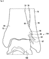
- Figure 4 shows an anterior view of the anatomy of a distal tibiofibular syndesmosis of a left human foot.
- the distal tibiofibular syndesmosis is formed by two bones and four ligaments.
- the two bones forming the osseous part of the syndesmosis are the distal tibia 60 on the medial and the fibula 50 on the lateral side.
- the ankle joint is formed by the connection of three bones.
- the top of the talus 160 fits inside a socket that is formed by the lower end of the distal tibia 60 and the distal fibula 50.
- the bottom of the talus 160 sits on the calcaneus.
- the two bones are linked by the four ligaments of the distal tibiofibular syndesmosis, which are the anterior inferior tibiofibular ligament (AITFL), the posterior inferior tibiofibular ligament (PITFL), the transverse ligament (TL), and the inter-osseous ligament (IL).
- the anterior view of the distal tibiofibular syndesmosis shows only two of these four ligaments, i.e. the anterior inferior tibiofibular ligament (AITFL) 62, and the interosseous ligament (IL) 69.
- the anterior inferior tibiofibular ligament (AITFL) 62 runs from the anterolateral tibia at Chaput's tubercle 66 laterally and inferiorly to the anterior lateral malleolus at Wagstaffe's tubercle 67.
- the interosseous ligament (IL) 69 is the distal continuation of the interosseous membrane forming a strong ligament that unites the distal tibia 60 and the distal fibula 50.
- Figure 5 shows a lateral view of the distal tibiofibular syndesmosis of a left human foot.
- the lateral view of the distal tibiofibular syndesmosis shows three of the four above mentioned ligaments, i.e. the anterior inferior tibiofibular ligament (AITFL) 62, the posterior inferior tibiofibular ligament (PITFL) 64, and the transverse ligament (TL) 65.
- the distal fibula 50 with its lateral surface 78 is seen in front of the lateral surface 74 of the distal tibia 60.
- the posterior inferior tibiofibular ligament (PITFL) 64 courses from Volkmann's tubercle 68 on the tibia 60 to the posterior lateral malleolus of the distal fibula 50.
- the transverse ligament 65 also known as inferior transverse ligament, is located just inferior and deep to the posterior inferior tibiofibular ligament (PITFL) 64, extending from the posterior lateral malleolus to the posterior tibia and posterior surface of the medial malleolus.
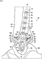
- Figures 6 and 7 show a device 80 for distal tibiofibular syndesmosis fixation.
- the device 80 is fixated to the distal tibiofibular syndesmosis of a left human foot.
- Figure 6 shows an anterior view
- figure 7 shows a lateral view.
- ligaments 62, 64, 65, 69 may be ruptured, they are drawn with dashed lines in figures 6 and 7 .
- the device 80 for distal tibiofibular syndesmosis fixation comprises a bone fixation plate 10 similar to the one of figures 1 to 3 .
- the bone fixation plate 10 has an elongate body 12 which has a proximal end 14, a distal end 16, an inner surface 18 and an outer surface 20.
- the bone fixation plate 10 further comprises a first wing 24 and a second wing 26 which are adapted to be arranged on the lateral surface 78 of the fibula 50.
- the two wings 24, 26 are arranged symmetrically with respect to the elongate body 12.
- the bone fixation plate 10 is fixated to the fibula 50 using screws 34 in holes 32 in the elongate body 12 of the bone fixation plate 10.
- the ruptured ligaments of the distal tibiofibular syndesmosis are repaired using three flexible strands 100, 102, 104 which are fixated at the bone fixation plate 10 and the medial surface 72 of the tibia 60. These three flexible strands are the first flexible strand 100, the second flexible strand 102, and the third flexible strand 104, which are unconnected to one another.
- Figure 6 shows the first flexible strand 100 and the second flexible strand 102.
- Figure 7 shows the first flexible strand 100 and the third flexible strand 104.
- the first and third flexible strands 100, 104 are used.
- the first flexible strand 100 is fixated with its first end 106 at the first hole 28 of the first wing 24 of the bone fixation plate 10 using a button 144 on the outer surface 20 of the first wing 24 of the bone fixation plate 10.
- the third flexible strand 104 is fixated with its first end 114 at the second hole 30 of the second wing 26 of the bone fixation plate 10 using a button 144 on the outer surface 20 of the second wing 26 of the bone fixation plate 10.
- Figure 7 only shows the part of the first and third flexible strands 100, 104 between the wings 24, 26 and the first hole 118 and the third hole 122 of the tibia 60.
- Figure 7 shows only the first and third flexible strand 100, 104, while the second flexible strand 102 is not displayed.
- the first flexible strand 100 runs from the button 144 of the first wing 24 to the first anterior position 126 on the lateral surface 74 of the tibia 60, where it enters the first hole 118 in the tibia 60 through the first bone orifice 162, to the first position 128 (e.g., anterior) on the medial surface 72 of the tibia 60, where it is fixated using a button 144.
- This can also be seen in figure 8 .
- each of the flexible strands 100, 102, 104 of this embodiment is a suture-button construct, each suture is drawn with four lines corresponding to the four fibers or threads of the suture.
- the third flexible strand 104 runs from the button 144 of the second 26 wing to the second posterior position 130 on the lateral surface 74 of the tibia 60, where it enters the third hole 122 in the tibia 60 through the second bone orifice 164, to the second position 132 (e.g., posterior) on the medial surface 72 of the tibia 60, where it is fixated using a button 144.
- This can also be seen in figure 8 .
- the second flexible strand 102 is fixated with its first end 110 at a hole 32 in the elongate body 12 of the bone fixation plate 10 using a button 144 on the outer surface 20 of the elongate body 12 of the bone fixation plate 10.
- the second flexible strand 102 runs through the second hole 120 in the tibia 60 and the hole 124 in the fibula and is fixated with its second end 112 at the medial surface 72 of the tibia 60 using a button 144. This can also be seen in figure 9 .
- the button 144 which rests on the medial surface 72 of the tibia 60 may for example be pulled through the second hole 120 of tibia 60 from the lateral surface 74 of tibia 60 and flipped to rest on the medial surface 72 of the tibia 60. This may be done without pulling the button 144 through the fibula 50.
- a modification of the bone fixation plate 10 may have wings 24, 26 moved further distally to approximate to the anatomical insertion point of the ligaments in fibula.
- Figures 8 and 9 show sectional views at different levels of the embodiment of figures 6 and 7 .
- the sectional view is at the level of the first and third flexible strands 100, 104.
- the sectional view is at the level of the second flexible strand 102. Both figure 8 and figure 9 are inferior views.
- Figure 8 shows an inferior, sectional view at the level of the first and third flexible strands 100, 104. This section is at the height of the tibiofibular joint 134.
- Figure 8 shows the tibia 60 on the left and the fibula 50 on the right.
- the bone fixation plate 10 is arranged on top of the lateral surface 78 of the fibula 50.
- the elongate body 12 of the bone fixation plate 10 is arranged on the center of the lateral surface 78 of the fibula 50.
- the first wing 24 of the bone fixation plate 10 extends from the elongate body 12 of the bone fixation plate 10 towards the anterior surface 54 of the distal fibula 50, near where the first hole 28 of the first wing 24 is arranged.
- the first hole 28 of the first wing 24 does not fully contact the distal fibula 50.
- the second wing 26 of the bone fixation plate 10 extends from the elongate body 12 of the bone fixation plate 10 towards the posterior surface 56 of the distal fibula 50, near where the second hole 30 of the second wing 26 is arranged.
- the second hole 30 of the second wing 26 does not fully contact the distal fibula 50.
- the first flexible strand 100 which is fixated at a button 144 at the outer surface 20 of the first wing 24 of the bone fixation plate 10 runs through the first hole 28 towards the lateral surface 74 of the tibia 60, where it enters at the first anterior position 126 the first hole 118 in tibia 60 through the first bone orifice 162.
- the first flexible strand 100 does not run through the fibula 50, instead it passes sideward at the fibula.
- the first flexible strand 100 then continues to go through the first hole 118 and is fixated with another button 144 on the medial surface 72 of the tibia 60.
- This button 144 is larger than the orifice, wherein the first hole 118 leaves the medial surface 72 of the tibia 60 at the first position 128 (e.g., anterior) on the medial surface 72 of the tibia 60. This button 144 rests on the outside of the bone on the medial surface 72 of tibia 60.
- the third flexible strand 104 which is fixated at a button 144 at the outer surface 20 of the second wing 24 of the bone fixation plate 10 runs through the second hole 30 towards the lateral surface 74 of the tibia 60, where it enters at the second posterior position 130 the third hole 122 in tibia 60 through the second bone orifice 164.
- the third flexible strand 104 does not run through the fibula 50 instead it passes sideward at the fibula.
- the third flexible strand 104 then continues to go through the third hole 122 and is fixated with another button 144 on the medial surface 72 of the tibia 60.
- This button 144 is larger than the orifice, wherein the third hole 122 leaves the medial surface 72 of the tibia 60 at the second position 132 (e.g., posterior) on the medial surface 72 of the tibia 60. This button 144 rests on the outside of the bone on the medial surface 72 of tibia 60.
- Figure 9 shows an inferior, sectional view at the level of the second flexible strand 102. This section is at a height slightly above the upper end of the distal tibiofibular joint articular cartilage.
- Figure 9 shows the tibia 60 on the left and the fibula 50 on the right.
- the bone fixation plate 10 is arranged on top of the lateral surface 78 of the fibula 50.
- the elongate body 12 of the bone fixation plate 10 is arranged on the center of the lateral surface 78 of the fibula 50.
- the second flexible strand 102 which is fixated at a button 144 at the outer surface 20 of the elongate body 12 of the bone fixation plate 10, runs through a hole 32 in the elongate body 12 of the bone fixation plate 10, then enters the hole 124 in the fibula 50, exits the fibula 50, runs between the medial surface 76 of the fibula and the lateral surface 74 of the tibia, then enters the second hole 120 in the tibia 60 and is fixated with yet another button 144 on the medial surface 72 of the tibia 60.
- This button 144 is larger than the orifice, wherein the second hole 120 leaves the medial surface 72 of the tibia 60 on the medial surface 72 of the tibia 60.
Landscapes
- Health & Medical Sciences (AREA)
- Orthopedic Medicine & Surgery (AREA)
- Surgery (AREA)
- Life Sciences & Earth Sciences (AREA)
- Heart & Thoracic Surgery (AREA)
- Nuclear Medicine, Radiotherapy & Molecular Imaging (AREA)
- Engineering & Computer Science (AREA)
- Biomedical Technology (AREA)
- Neurology (AREA)
- Medical Informatics (AREA)
- Molecular Biology (AREA)
- Animal Behavior & Ethology (AREA)
- General Health & Medical Sciences (AREA)
- Public Health (AREA)
- Veterinary Medicine (AREA)
- Surgical Instruments (AREA)
- Prostheses (AREA)
Abstract
The present disclosure relates to bone fixation plate and a system for treatment of injuries of the distal tibiofibular syndesmosis. The bone fixation plate provides an improved stability to the distal fibula
Description
- The present disclosure relates to ankle surgery and, more particularly, to a bone fixation plate, and a device for distal tibiofibular syndesmosis fixation.
- Ankle injuries are among the most common of the bone and joint injuries. The ankle joint is formed of three bones coming together: the tibia which makes up the medial, or inside, anklebone; the fibula which parallels the tibia and makes up the lateral, or outside, anklebone; and the talus. The far ends of the tibia and fibula are known as the malleoli and together they form an arch that sits on top of the talus.
- A fibrous membrane (the joint capsule) encases the joint architecture and is lined with a smoother layer called the synovium. The joint capsule contains the synovial fluid produced by the synovium. The synovial fluid allows for smooth movement of the joint surfaces. The ankle joint is stabilized by three groups of ligaments, which are fibers that hold these bones in place.
- Surgery to repair an ankle fracture is indicated for patients who suffer a displaced ankle fracture involving the bone on the inside to the ankle (tibia), the bone on the outside of the ankle (fibula), or both. As the fibula is much narrower than the tibia at the ankle joint, a fracture of the fibula is much more frequent than a fracture of the tibia. One injury that may occur in the ankle is a disruption of the distal tibiofibular syndesmosis. A syndesmostic injury is a disruption of the strong fibrous ligaments that hold the fibula and tibia together near the ankle joint. If the syndesmosis is disrupted, then the ankle joint will be unstable and surgery is usually indicated.
- The distal tibiofibular syndesmosis is usually described as being comprised of four ligaments. These ligaments are the anterior inferior tibiofibular ligament (AITFL), the posterior inferior tibiofibular ligament (PITFL), the transverse ligament (TL), and the interosseous ligament (IL). The primary role of these ligaments is to act as tensile members that stabilize the fibula within the distal tibiofibular joint. Injury to these ligaments, either isolated or concomitant with fractures of one or both the tibia and fibula, results in diastasis of the ankle joint which manifests as ankle instability.
- As used herein, the term "syndesmosis" is intended to mean an articulation of bones, in particular those portions of the tibia and fibula forming the ankle, in which the bones are joined by means of a ligament. Thereby, the distal tibiofibular syndesmosis is a syndesmotic joint formed by two bones and four ligaments. The distal tibia and fibula form the osseous part of the syndesmosis and are linked by the above mentioned anterior inferior tibiofibular ligament (AITFL), the posterior inferior tibiofibular ligament (PITFL), the transverse ligament (TL), and the interosseous ligament (IL). Although the syndesmosis is a joint, in the literature the term syndesmotic injury is used to describe injury of the syndesmotic ligaments. Sometimes the transverse ligament (TL) is also called inferior transverse ligament of the tibiofibular syndesmosis. As the transverse ligament (TL) lies in front of the posterior inferior tibiofibular ligament (PITFL) and is very close to the latter, for purposes of reconstruction, these two ligaments may be regarded as a single ligament. Therefore, although there are four ligaments in the distal tibiofibular syndesmosis, if this disclosure mentions three ligaments of the distal tibiofibular syndesmosis, it is understood that the transverse ligament (TL) and the posterior inferior tibiofibular ligament (PITFL) are counted as a single ligament.
- Improved bone fixation plates for the distal fibula are disclosed herein. A bone fixation plate should provide improved stability to the distal fibula.
- A further object is to provide a single device which may be used to treat most kinds of distal tibiofibular syndesmosis injuries, i.e. fractures of the distal fibula and injuries of the anterior inferior tibiofibular ligament (AITFL), the posterior inferior tibiofibular ligament (PITFL), and the transverse ligament (TL), in a better and easier way than devices of the prior art. The device should be able to reconstruct the function of the natural ligaments, i.e. the reconstructed ligaments should be at nearly the same place as the natural ligaments and have a similar functionality. Further, the reconstructed ligaments should be flexible, resilient, but also resistive, durable and robust.
- Solutions to the problem(s) are described herein.
- A bone fixation plate may be used for treatment of fractures of the distal fibula, including fractures of the distal fibula which occur together with injuries of the four ligaments of the distal tibiofibular syndesmosis, i.e. the anterior inferior tibiofibular ligament (AITFL), the posterior inferior tibiofibular ligament (PITFL), the transverse ligament (TL), and the interosseous ligament (IL).
- A bone fixation plate comprises an elongate body which is adapted to be placed on the distal fibula. The elongate body has a proximal end, a distal end, an inner surface, and an outer surface. An elongate body of the bone fixation plate may further comprise at least one lateral edge, in particular a single circumferential edge, which is arranged between the inner surface and the outer surface of the bone fixation plate. The elongate body of the bone fixation plate may comprise a single edge, which may be circumferential.
- The elongate body of the bone fixation plate may comprise four edges, i.e. a superior or upper edge, an inferior or lower edge, an anterior edge, and a posterior edge.
- The elongate body further comprises at least one hole which is adapted for a screw to be fixated therein and/or a flexible strand, or construct thereof, to be guided through the hole. An end of the flexible strand may be guided through the at least one hole of the elongate body and may be fixated at a button which rests at the at least one hole on the outer surface of the elongate body. The at least one hole may be used to attach the bone fixation plate to the distal fibula. This is can be achieved using a plurality of screws. A screw used for the at least one hole may be a locking or a non-locking screw.
- A flexible strand may be a suture, a tape, etc.. A flexible strand construct may be a flexible strand (e.g., suture, tape, etc.) in combination with a fixation device, such as a button or an anchor.
- An elongate body may further comprise at least one wing which is connected with the elongate body and which extends from a lateral edge of the elongate body.
- The at least one wing may be a part of the elongate body.
- The at least one wing may comprise at least one hole for fixing a flexible strand to the bone fixation plate. Each wing may comprise a single hole for fixing a flexible strand to the bone fixation plate. The flexible strand may be fixated to the bone fixation plate by fixing the flexible strand to a button which rests at the at least one hole on the surface of the at least one wing.
- The at least one wing may extend from the lateral edge of the elongate body in a direction which may be orthogonal to the longitudinal axis of the elongate body. It may also extend under an angle either towards the proximal or distal end of the bone fixation plate.
- The direction under which the at least one wing extends from the lateral edge of the elongate body may have an angle between 20° and 70° with respect to the plane of the elongate body.
- The elongate body may be adapted to be placed on the distal fibula, the proximal end is adapted to face an upper part of the distal fibula, the distal end is adapted to face a distal end the distal fibula, the inner surface is adapted to face the lateral surface of the distal fibula, the outer surface is adapted to face away from the lateral surface of the distal fibula, and the at least one wing is adapted to extend from a lateral edge or a part of the lateral circumferential edge of the elongate body towards the anterior surface and/or the posterior surface of the distal fibula.
- When the bone fixation plate is used as intended, i.e. when the bone fixation plate is fixated onto the distal fibula, in particular to the lateral surface of the distal fibula, the proximal end of the bone fixation plate points towards the proximal end of the fibula or the knee, and the distal end of the bone fixation plate points towards the distal end of the fibula or towards the ankle.
- The term "used as intended" may, for example, mean that the relevant object is located at the position and/or is arranged in the orientation at/in which it should be used. For example, a bone fixation plate is located on top of the distal fibula.
- A bone fixation plate may comprise two wings, e.g., a first wing and a second wing. A first wing and second wing may be arranged on opposite sides at the lateral edge of the elongate body.
- Two wings may be arranged symmetrically with respect to a plane which is orthogonal to the outer surface or the elongate body and parallel to the longitudinal axis of the elongate body, wherein the longitudinal axis of the elongate body lies within said plane. This plane may also be described as the plane which goes through the longitudinal axis of the elongate body and is orthogonal to the outer surface of the elongate body. In an alternate embodiment, the wings may be arranged asymmetrically either in length, angulation towards inferior/posterior or angulation towards medial/lateral.
- A first wing and a second wing may be adapted to be arranged symmetrically with respect to a coronal plane through the distal fibula or a plane along the longitudinal axis of the elongate body which is orthogonal to the outer surface of the elongate body. When referring to a different location with respect to a superior- inferior direction, this disclosure refers to different level or height.
- A first wing may comprise a first hole which is adapted for a first flexible strand to be guided through the hole, and a second wing may comprise a second hole which is adapted for a second flexible strand to be guided through the hole. The first flexible strand may be fixated to a button which may rest on the first hole of the first wing. The second flexible strand may be fixated to a button which may rest on the second hole of the second wing.
- Each wing may comprise at least one hole which is adapted for a flexible strand to be guided through the hole. The flexible strand may be fixated to the bone fixation plate by fixing the flexible strand to a button which may rest on the at least one hole. Each wing may comprise a single hole which is adapted for a flexible strand to be guided through the hole. The flexible strand may be fixated to the bone fixation plate by fixing the flexible strand to a button which rests on the single hole of each wing.
- A first wing may be adapted to extend towards the anterior surface of the distal fibula, and the second wing may be adapted to extend towards the posterior surface of the distal fibula.
- In an embodiment, the bone fixation plate does not extend up to the anterior or posterior surface or border of the distal fibula. Thereby, the bone fixation plate does not interfere, in particular contact or touch, with the distal tibia, even when the ankle or foot is distorted.
- The bone fixation plate may extend from a middle vertical axis of the lateral surface of the fibula to a point on the distal fibula which has an angle of about 40° to about 90° with respect to the center of the distal fibula. This angle may be about 80°, about 70°, about 60°, about 55°, about 50°, about 45°, or about 40°.
- The at least one wing, e.g., a first wing and/or a second wing, may be arranged at approximately the same height as the fibular notch of the tibia or at approximately the same height as the tibiofibular joint.
- The at least one wing, e.g., a first wing and/or a second wing, may be arranged at approximately the same height as the insertion points of the anterior inferior tibiofibular ligament or the posterior inferior tibiofibular ligament. The first wing may be arranged at approximately the same height as the anterior inferior tibiofibular ligament. The second wing may be arranged at approximately the same height as the posterior inferior tibiofibular ligament.
- The at least one wing may be arranged at approximately the same height as the Chaput tubercle of the tibia or at the same height as the Volksmann's tubercle of the tibia.
- In an embodiment, the first wing is arranged at the same height as the Chaput tubercle of the tibia, and the second wing is arranged at the same height as the Volksmann's tubercle of the tibia.
- The center of each wing may be arranged at a level in the middle between the proximal and the distal end, wherein "the middle" is at a point about 30% to about 70%, about 40% to about 60%, about 45% to about 60%, about 50% to about 60%, about 40% to about 55%, about 40% to about 50%, about 45% to about 50%, or about 45% to about 55% of the total length of the elongate body from the distal end. In an embodiment, the middle may be a point about 30%, about 40%, about 45%, about 50%, about 55%, about 60%, about 65%, or about 70% of the total length of the elongate body from the distal end.
- Each wing may also be arranged in the inferior third, fourth, or fifth of the elongate body.
- Each wing may be arranged about 10 to 20% of the total length of the elongate body below the middle of the elongate body.
- The bone fixation plate may comprise titanium, stainless steel, PEEK or any other surgically acceptable material having a mechanical strength sufficient for a bone fixation plate.
- The device for distal tibiofibular syndesmosis fixation is intended to treat fractures of the distal fibula using the bone fixation plate and to assist repair the function of the ligaments of a natural distal tibiofibular syndesmosis using flexible strands.
- A device for distal tibiofibular syndesmosis fixation comprises a bone fixation plate and at least one flexible strand. The at least one flexible strand has a first end and a second end, wherein the first end of the at least one flexible strand preferably is adapted to be guided through the at least one hole of the bone fixation plate and the second end of the at least one flexible strand preferably is adapted to be fixated on the medial surface of the tibia. The first end of the at least one flexible strand may be fixated to a button which may rest on the at least one hole of the bone fixation plate. The second end of the at least one flexible strand may be fixated to a button which rests on the medial surface of the tibia. Here, the at least one flexible strand is preferably adapted to be arranged in a hole through the tibia bone and/or the distal fibula.
- In a preferred embodiment, a device for syndesmosis fixation comprises a bone fixation plate having an elongate body with a proximal end, a distal end, an inner surface, an outer surface, and a first and a second lateral edge arranged between the inner surface and the outer surface. The bone fixation plate further comprises a first wing extending at an angle from said first lateral edge at a location between said proximal end and said distal end and a second wing extending at the same angle from said second lateral edge at a location between said proximal end and said distal end. The syndesmosis fixation device further comprises a first flexible strand fixated within a first hole of said first wing, a second flexible strand fixated within a second hole of said second wing, and a screw or a third flexible strand fixated within a third hole extending through said elongated body.
- The first wing and the second wing may be arranged at a distance of approximately one third of a total length of the elongated body as measured from its distal end.
- Preferably, at least one of said first wing and said second wing is bendable relative to said elongated body.
- The following may apply to each flexible strand of the present disclosure. Each end of each flexible strand, which is fixated or attached to or at the bone fixation plate, may be fixated to the bone fixation plate using a button or an anchor. This may be done by fixing an end of the flexible strand to the button which rests on at a hole on the surface of the bone fixation plate. The end of the flexible strand may be guided through a hole extending through the bone fixation plate and the end of the flexible strand may be fixated to the button.
- The following may apply to each flexible strand of the present disclosure. Each end of each flexible strand which is fixated on a surface of a bone may be fixated there by fixing an end of the flexible strand to a button which rests on the surface of the bone. This may be done by guiding the end of the flexible strand through a hole extending to the surface of the bone and by fixing the end of the flexible strand to the button.
- Each flexible strand which according to this disclosure is adapted to be fixated with its first end to the bone fixation plate and with its second end to the medial surface of the tibia may e.g. be a suture or a suture-button construct. Such a suture-button construct may comprise a suture connected between a first button and a second button.
- According to another embodiment, the device comprises three flexible strands, i.e. a first flexible strand (e.g., a first suture or construct thereof), a second flexible strand (e.g., a second suture or construct thereof), and a third flexible strand (e.g., a third suture or construct thereof), wherein each flexible strand (e.g., suture or construct thereof) has a first and a second end, and the bone fixation plate comprises two wings, i.e. the first wing and the second wing. Here, each flexible strand is used to repair one ligament of the three ligaments of the distal tibiofibular syndesmosis, wherein the transverse ligament (TL) and the posterior inferior tibiofibular ligament (PITFL) are counted as a single ligament.
- The first wing and the second wing may be arranged on opposite sides on the lateral edge of the elongate body. In an embodiment, the first wing and the second wing are symmetrical with respect to a coronal plane through the distal fibula or a plane along the axis of the elongate body which is orthogonal to the outer surface of the elongate body. In an embodiment, the first wing and the second wing are asymmetrical with respect to a coronal plane through the distal fibula or a plane along the axis of the elongate body which is orthogonal to the outer surface of the elongate body.
- The first wing is adapted to extend towards the anterior surface of the distal fibula and the second wing is adapted to extend towards the posterior surface of distal fibula. However, the wings should not interfere with the lateral surface of the tibia or any other anatomical part which might hinder movement of the patient.
- Each wing may directly contact the lateral surface of the fibula, however, the hole of each wing should not fully contact the lateral surface of the fibula. A gap between the wing at the position of the hole and the fibula allows a flexible strand to pass through the hole in the wing and along the fibula at the outside of the fibula. The flexible strand(s) may be fixated at the wing using a button, a an anchor, or a button and anchor. To adapt the wings to a specific anatomy, at least one wing may be malleable to bend the at least one wing. Furthermore, at least one wing may be cut if needed.
- Each wing comprises at least one hole for fixing a flexible strand. In an embodiment, each wing has a single hole.
- The first end of the first flexible strand may be adapted to be fixated at the first hole of the first wing, and the second end of the first flexible strand may be adapted to be fixated at the medial surface of the tibia, wherein the first flexible strand is adapted to extend through a first hole in the tibia extending from an anterior position on the lateral surface of the tibia to a position (e.g., anterior) on the medial surface of the tibia. Both ends of the first flexible strand may be fixated using buttons.
- The first end of the second flexible strand may be adapted to be fixated at the at least one hole in the elongate body, and the second end of the second flexible strand is adapted to be fixated at the medial surface of the tibia. The second flexible strand may be adapted to extend through a hole in the fibula and a second hole in the tibia. The hole in the fibula is adapted to extend from the lateral surface to the medial surface of the fibula, and the second hole in the tibia is adapted to extend from the lateral surface to the medial surface of the tibia, wherein the hole in the fibula is aligned with the second hole in the tibia. This alignment need not be perfect. When a flexible strand (e.g., suture, tape, etc.) may go through the two holes without being harmed is sufficient.
- The first end of a third flexible strand may be adapted to be fixated at the second hole of the second wing, and the second end of the third flexible strand may be adapted to be fixated at the medial surface of the tibia. A third flexible strand may be adapted to extend through a third hole in the tibia extending from a posterior position on the lateral surface of the tibia to a position (e.g., a posterior position) on the medial surface of the tibia.
- The position where a first flexible strand is adapted to be fixated on the medial surface of the tibia may be anterior as compared to the position where a third flexible strand is adapted to be fixated on said medial surface of the tibia.
- A first hole through the tibia, through which the first flexible strand is adapted to run, may be arranged at the level of the tibiofibular joint. A third hole through the tibia, through which the third flexible strand is adapted to run, may be arranged at the level of the tibiofibular joint. The first hole and the third hole may be arranged at the same height or level. The two wings and the two holes through the tibia may be arranged at the same level, which may be at the level of the tibiofibular joint.
- The hole for the second flexible strand, which may be adapted to be arranged in the fibula and in the tibia may be arranged above the level of the tibiofibular joint, or even at the level of the interosseous ligament or at a level slightly above the upper end of the distal tibiofibular joint articular cartilage.
- Any flexible strand may be adapted to be arranged transversally or in a transverse plane.
- The position where the first flexible strand is adapted to be fixated on the medial surface of the tibia may be at approximately the same height as the position where the third flexible strand is adapted to be fixated on said medial surface of the tibia.
- The first end or the second end of the at least one flexible strand or the first end or the second end of the first, second, or third flexible strand may be adapted to be fixated at the tibia, the at least one hole of the bone fixation plate, the first hole of the first wing or the second hole of the second wing using a button.
- In an embodiment, the first flexible strand and third flexible strand are not parallel to each other. When viewed in a transverse plane and from the medial surface of the tibia, the first and third flexible strands are adapted to be divergent towards the lateral surface of the tibia, which increases rotational stability of the syndesmosis.
- The first flexible strand, the second flexible strand, and the third flexible strand each may be adapted to lie approximately within a transverse plane. For example, the first flexible strand and the second flexible strand may be adapted to lie approximately within the same transverse plane, while the second flexible strand is adapted to lie in a different transverse plane.
- The first flexible strand, the second flexible strand, and the third flexible strand may be adapted such that projections of the first flexible strand, the second flexible strand, and the third flexible strand into a transverse plane are divergent when viewed from the medial surface of the tibia. In an embodiment, the projection of the second flexible strand is arranged between the projections of the first flexible strand and the third flexible strand. These features may have the advantage of increasing rotational stability of the syndesmosis.
- In an embodiment, a device for distal tibiofibular syndesmosis fixation may be installed as follows. In a first step, a bone fixation plate is fixated on the lateral surface of the distal fibula. Fixation may be achieved by screwing a bone fixation plate to the distal fibula using holes in the elongate body. The holes may be arranged to achieve a good healing effect for the fibula.
- Further holes in the bone fixation plate are present for fixing flexible strands to the plate which are installed in subsequent steps. Three flexible strands are utilized for the anterior inferior tibiofibular ligament (AITFL), the posterior inferior tibiofibular ligament (PITFL), and the interosseous ligament (IL In an embodiment, each flexible strand is a suture.
- The order in which the three flexible strands are fixated to the tibia and the fibula does not matter. In an embodiment, the second flexible strand is fixated first because the drilling or hole through the tibia is at a right angle with respect to the lateral surfaces of the tibia and fibula. Also, the tibia and the fibula may be fixated to each other by installing the second flexible strand, and as a consequence the tibia and fibula then are in the place where they should be after the surgery and no repositioning of these bones is necessary.
- The second flexible strand may include a first button, which may be oblong and may rest on the medial surface of the tibia, and a second button, which may be round and may rest on the outer surface of the elongate body of the bone fixation plate which itself is on the lateral surface of the fibula. The second flexible strand may also include a flexible member or thread, which is arranged between the first and the second button and which has two free ends emerging from the second button at its rear end. For installation of the second flexible strand, pull-through flexible strands may be used, which are then removed after installation.
- The second flexible strand may be installed by drilling a hole, called "a second hole", through all four cortices of the tibia and the fibula, wherein the hole through the fibula should be aligned with the hole in the elongate body of the bone fixation plate, which is used to fix the second flexible strand. In an embodiment, a K-wire is first guided through the fibula and tibia, and then a hole is drilled along the K-wire. The hole may be in the transmalleolar plane which is about 30° anterior to the coronal plane using a 3.5 mm drill bit. A needle and pull-through flexible strands are passed along the drill hole and out the intact medial skin until the first button exits the tibia on the medial surface. Then the first button is turned using the pull-through sutures. Afterwards, the first button is pulled back by pulling on the second button and the free ends of the second button. By pulling back the second button, the first button is tightened on the medial surface of the tibia.
- In a next step, by pulling on the free ends of the second button, the second button is tightened on the bone fixation plate on the fibula and then by pulling further on the free ends of the second button, the fibula is pulled next to the tibia such that the syndesmosis is reduced.
- In a next step, the construct is secured with three half-hitches. The flexible strand ends are cut at least 2 cm long to allow the knot and flexible strand to lie down, reducing knot prominence. Then the pull-through flexible strands are cut and removed.
- In an embodiment, a knotless suture or construct thereof is utilized.
- Then the first and third flexible strands are installed. To this end, two holes, called "a first hole" and "a third hole", are drilled through the tibia. The first hole in the tibia extends from an anterior position on the lateral surface of the tibia to a position (e.g., anterior) on the medial surface of the tibia. The third hole in the tibia extends from a posterior position on the lateral surface of the tibia to a position (e.g., posterior) on the medial surface of the tibia. In an embodiment, the level of the first and third holes is the same. In an embodiment, the level of the first and third holes is offset. In another embodiment, the level is at the level of the tibiofibular joint. Then the first flexible strand is threaded through the first hole, and the third flexible strand is threaded through the third hole.
- The first flexible strand may be fixated at the first wing using a button. The third flexible strand may be fixated at the second wing using a button.
- In an embodiment, the first and third flexible strands are fixated at the bones using buttons.
- In the following, embodiments will be described by way of example, without limitation of a general inventive concept, with reference to the drawings.
-
Figures 1 ,2 and3 show side, top, and perspective views of a bone fixation plate, respectively. -
Figures 4 and5 show anterior and lateral views, respectively, of the distal tibiofibular syndesmosis of a left human foot. -
Figures 6 and7 show anterior and lateral views, respectively, of a device for distal tibiofibular syndesmosis fixation when fixated to the distal tibiofibular syndesmosis of a left human foot. -
Figure 8 shows a sectional view of the embodiment ofFigure 6 and7 , wherein the section is at the level of the first and third flexible strands. -
Figure 9 shows a sectional view of the embodiment ofFigures 6 and7 , wherein the section is at the level of the second flexible strand. -
Figures 1 ,2 and3 show side, top and perspective views of abone fixation plate 10. - The
bone fixation plate 10 comprises anelongate body 12 which has aproximal end 14, adistal end 16, an inner surface 18 (as seen inFigure 1 ), and anouter surface 20. Thebone fixation plate 10, in particular theelongate body 12, is adapted to be arranged on the outer surface of thedistal fibula 50. - The
elongate body 12 comprises in this embodiment elevenholes 32 in which screws 34 (as seen inFigures 6 and7 ) and/or a second flexible strand 102 (as seen inFigures 6 to 9 ) may be fixated. Thescrews 34 may be locking or non-locking. Thescrews 34 may be used to fix theelongate body 12 of thebone fixation plate 10 to thedistal fibula 50, which might be fractured. - The
elongate body 12 haslateral edges 22 arranged between theinner surface 18 and theouter surface 20. - The
bone fixation plate 10 further comprises afirst wing 24 and asecond wing 26, which extend from the lateral edges 22 of theelongate body 12. Thefirst wing 24 is adapted to extend from thelateral surface 78 of thedistal fibula 50 towards theanterior surface 54 of thedistal fibula 50 and thesecond wing 26 is adapted to extend from thelateral surface 78 of thedistal fibula 50 towards theposterior surface 56 of the fibula 50 (as seen inFigures 7 and8 ). - The
wings distal tibia 60 at the anterior and posterior ends 54, 56 of thefibula 50. - The
first wing 24 comprises afirst hole 28 at which a firstflexible strand 100 may be fixated and thesecond wing 26 comprises asecond hole 30 at which a thirdflexible strand 104 may be fixated. In one non-limiting embodiment, the firstflexible strand 100 and the thirdflexible strand 104 are unconnected to one another. - The two
wings elongate body 12. The twowings elongate body 12 which is orthogonal to theouter surface 20 of theelongate body 12. - The part of the
elongate body 12 that is between theproximal end 14 and theseventh hole 32 when counted from theproximal end 14 may be symmetrical with respect to the longitudinal axis of theelongate body 12. The lower part of theelongate body 12 is adapted to fit on the lower end of thedistal fibula 50, and is therefore not symmetrical with respect to the longitudinal axis of theelongate body 12. - The
wings elongate body 12 from thedistal end 16 of theelongate body 12. However, the length of theelongate body 12 and the position of thewings fibula 50. The positon of thewings second bone orifices first bone orifice 162 is located on thelateral surface 74 of thetibia 60 at the position where thefirst hole 118 leaves thetibia 60. Thesecond bone orifice 164 is located on thelateral surface 74 of thetibia 60 at the position where thethird hole 122 leaves thetibia 60. The first andsecond bone orifices Figures 6 to 9 . - Next to the
distal end 16 of theelongate body 12 of thebone fixation plate 10 aresmall holes 33, which are much smaller than theholes 32. Thesesmall holes 33 may be used for K-wires or flexible strands. Thebone fixation plate 10 may first be fixated with itsdistal end 16 to thedistal fibula 50 using K-wires and after wards with itsproximal end 14 to thedistal fibula 50 usingscrews 34 in theholes 32. -
Figure 4 shows an anterior view of the anatomy of a distal tibiofibular syndesmosis of a left human foot. The distal tibiofibular syndesmosis is formed by two bones and four ligaments. The two bones forming the osseous part of the syndesmosis are thedistal tibia 60 on the medial and thefibula 50 on the lateral side. The ankle joint is formed by the connection of three bones. The top of thetalus 160 fits inside a socket that is formed by the lower end of thedistal tibia 60 and thedistal fibula 50. The bottom of thetalus 160 sits on the calcaneus. - The two bones are linked by the four ligaments of the distal tibiofibular syndesmosis, which are the anterior inferior tibiofibular ligament (AITFL), the posterior inferior tibiofibular ligament (PITFL), the transverse ligament (TL), and the inter-osseous ligament (IL). The anterior view of the distal tibiofibular syndesmosis shows only two of these four ligaments, i.e. the anterior inferior tibiofibular ligament (AITFL) 62, and the interosseous ligament (IL) 69.
- The anterior inferior tibiofibular ligament (AITFL) 62 runs from the anterolateral tibia at Chaput's
tubercle 66 laterally and inferiorly to the anterior lateral malleolus at Wagstaffe'stubercle 67. - The interosseous ligament (IL) 69 is the distal continuation of the interosseous membrane forming a strong ligament that unites the
distal tibia 60 and thedistal fibula 50. -
Figure 5 shows a lateral view of the distal tibiofibular syndesmosis of a left human foot. - The lateral view of the distal tibiofibular syndesmosis shows three of the four above mentioned ligaments, i.e. the anterior inferior tibiofibular ligament (AITFL) 62, the posterior inferior tibiofibular ligament (PITFL) 64, and the transverse ligament (TL) 65. The
distal fibula 50 with itslateral surface 78 is seen in front of thelateral surface 74 of thedistal tibia 60. - The posterior inferior tibiofibular ligament (PITFL) 64 courses from Volkmann's
tubercle 68 on thetibia 60 to the posterior lateral malleolus of thedistal fibula 50. Thetransverse ligament 65, also known as inferior transverse ligament, is located just inferior and deep to the posterior inferior tibiofibular ligament (PITFL) 64, extending from the posterior lateral malleolus to the posterior tibia and posterior surface of the medial malleolus. -
Figures 6 and7 show adevice 80 for distal tibiofibular syndesmosis fixation. Thedevice 80 is fixated to the distal tibiofibular syndesmosis of a left human foot.Figure 6 shows an anterior view, andfigure 7 shows a lateral view. - As the
ligaments figures 6 and7 . - The
device 80 for distal tibiofibular syndesmosis fixation comprises abone fixation plate 10 similar to the one offigures 1 to 3 . - The
bone fixation plate 10 has anelongate body 12 which has aproximal end 14, adistal end 16, aninner surface 18 and anouter surface 20. Thebone fixation plate 10 further comprises afirst wing 24 and asecond wing 26 which are adapted to be arranged on thelateral surface 78 of thefibula 50. The twowings elongate body 12. - The
bone fixation plate 10 is fixated to thefibula 50 usingscrews 34 inholes 32 in theelongate body 12 of thebone fixation plate 10. - The ruptured ligaments of the distal tibiofibular syndesmosis are repaired using three
flexible strands bone fixation plate 10 and themedial surface 72 of thetibia 60. These three flexible strands are the firstflexible strand 100, the secondflexible strand 102, and the thirdflexible strand 104, which are unconnected to one another.Figure 6 shows the firstflexible strand 100 and the secondflexible strand 102.Figure 7 shows the firstflexible strand 100 and the thirdflexible strand 104. - For repairing the anterior and posterior
tibiofibular ligaments flexible strands flexible strand 100 is fixated with itsfirst end 106 at thefirst hole 28 of thefirst wing 24 of thebone fixation plate 10 using abutton 144 on theouter surface 20 of thefirst wing 24 of thebone fixation plate 10. The thirdflexible strand 104 is fixated with itsfirst end 114 at thesecond hole 30 of thesecond wing 26 of thebone fixation plate 10 using abutton 144 on theouter surface 20 of thesecond wing 26 of thebone fixation plate 10.Figure 7 only shows the part of the first and thirdflexible strands wings first hole 118 and thethird hole 122 of thetibia 60.Figure 7 shows only the first and thirdflexible strand flexible strand 102 is not displayed. - The first
flexible strand 100 runs from thebutton 144 of thefirst wing 24 to the firstanterior position 126 on thelateral surface 74 of thetibia 60, where it enters thefirst hole 118 in thetibia 60 through thefirst bone orifice 162, to the first position 128 (e.g., anterior) on themedial surface 72 of thetibia 60, where it is fixated using abutton 144. This can also be seen infigure 8 . As each of theflexible strands - The third
flexible strand 104 runs from thebutton 144 of the second 26 wing to the secondposterior position 130 on thelateral surface 74 of thetibia 60, where it enters thethird hole 122 in thetibia 60 through thesecond bone orifice 164, to the second position 132 (e.g., posterior) on themedial surface 72 of thetibia 60, where it is fixated using abutton 144. This can also be seen infigure 8 . - For repairing the
interosseous ligament 69, the secondflexible strand 102 is fixated with itsfirst end 110 at ahole 32 in theelongate body 12 of thebone fixation plate 10 using abutton 144 on theouter surface 20 of theelongate body 12 of thebone fixation plate 10. The secondflexible strand 102 runs through thesecond hole 120 in thetibia 60 and thehole 124 in the fibula and is fixated with itssecond end 112 at themedial surface 72 of thetibia 60 using abutton 144. This can also be seen infigure 9 . Thebutton 144 which rests on themedial surface 72 of thetibia 60 may for example be pulled through thesecond hole 120 oftibia 60 from thelateral surface 74 oftibia 60 and flipped to rest on themedial surface 72 of thetibia 60. This may be done without pulling thebutton 144 through thefibula 50. - A modification of the
bone fixation plate 10 may havewings -
Figures 8 and9 show sectional views at different levels of the embodiment offigures 6 and7 . Infigure 8 the sectional view is at the level of the first and thirdflexible strands figure 9 the sectional view is at the level of the secondflexible strand 102. Bothfigure 8 andfigure 9 are inferior views. -
Figure 8 shows an inferior, sectional view at the level of the first and thirdflexible strands -
Figure 8 shows thetibia 60 on the left and thefibula 50 on the right. Thebone fixation plate 10 is arranged on top of thelateral surface 78 of thefibula 50. Theelongate body 12 of thebone fixation plate 10 is arranged on the center of thelateral surface 78 of thefibula 50. Thefirst wing 24 of thebone fixation plate 10 extends from theelongate body 12 of thebone fixation plate 10 towards theanterior surface 54 of thedistal fibula 50, near where thefirst hole 28 of thefirst wing 24 is arranged. Thefirst hole 28 of thefirst wing 24 does not fully contact thedistal fibula 50. Thesecond wing 26 of thebone fixation plate 10 extends from theelongate body 12 of thebone fixation plate 10 towards theposterior surface 56 of thedistal fibula 50, near where thesecond hole 30 of thesecond wing 26 is arranged. Thesecond hole 30 of thesecond wing 26 does not fully contact thedistal fibula 50. - The first
flexible strand 100 which is fixated at abutton 144 at theouter surface 20 of thefirst wing 24 of thebone fixation plate 10 runs through thefirst hole 28 towards thelateral surface 74 of thetibia 60, where it enters at the firstanterior position 126 thefirst hole 118 intibia 60 through thefirst bone orifice 162. The firstflexible strand 100 does not run through thefibula 50, instead it passes sideward at the fibula. The firstflexible strand 100 then continues to go through thefirst hole 118 and is fixated with anotherbutton 144 on themedial surface 72 of thetibia 60. Thisbutton 144 is larger than the orifice, wherein thefirst hole 118 leaves themedial surface 72 of thetibia 60 at the first position 128 (e.g., anterior) on themedial surface 72 of thetibia 60. Thisbutton 144 rests on the outside of the bone on themedial surface 72 oftibia 60. - The third
flexible strand 104 which is fixated at abutton 144 at theouter surface 20 of thesecond wing 24 of thebone fixation plate 10 runs through thesecond hole 30 towards thelateral surface 74 of thetibia 60, where it enters at the secondposterior position 130 thethird hole 122 intibia 60 through thesecond bone orifice 164. The thirdflexible strand 104 does not run through thefibula 50 instead it passes sideward at the fibula. The thirdflexible strand 104 then continues to go through thethird hole 122 and is fixated with anotherbutton 144 on themedial surface 72 of thetibia 60. Thisbutton 144 is larger than the orifice, wherein thethird hole 122 leaves themedial surface 72 of thetibia 60 at the second position 132 (e.g., posterior) on themedial surface 72 of thetibia 60. Thisbutton 144 rests on the outside of the bone on themedial surface 72 oftibia 60. -
Figure 9 shows an inferior, sectional view at the level of the secondflexible strand 102. This section is at a height slightly above the upper end of the distal tibiofibular joint articular cartilage.Figure 9 shows thetibia 60 on the left and thefibula 50 on the right. Thebone fixation plate 10 is arranged on top of thelateral surface 78 of thefibula 50. Theelongate body 12 of thebone fixation plate 10 is arranged on the center of thelateral surface 78 of thefibula 50. - The second
flexible strand 102 which is fixated at abutton 144 at theouter surface 20 of theelongate body 12 of thebone fixation plate 10, runs through ahole 32 in theelongate body 12 of thebone fixation plate 10, then enters thehole 124 in thefibula 50, exits thefibula 50, runs between themedial surface 76 of the fibula and thelateral surface 74 of the tibia, then enters thesecond hole 120 in thetibia 60 and is fixated with yet anotherbutton 144 on themedial surface 72 of thetibia 60. Thisbutton 144 is larger than the orifice, wherein thesecond hole 120 leaves themedial surface 72 of thetibia 60 on themedial surface 72 of thetibia 60. -
- 10
- bone fixation plate
- 12
- elongate body
- 14
- proximal end
- 16
- distal end
- 18
- inner surface
- 20
- outer surface
- 22
- lateral edge
- 24
- first wing
- 26
- second wing
- 28
- first hole for fixing a suture of the first wing
- 30
- second hole for fixing a suture of the second wing
- 32
- hole in the elongate body of the bone fixation plate
- 33
- small hole in the elongate body of the bone fixation plate
- 34
- screw
- 50
- fibula
- 54
- anterior surface of the distal fibula
- 56
- posterior surface of the distal fibula
- 58
- fibular notch
- 60
- tibia
- 62
- anterior inferior tibiofibular ligament
- 64
- posterior inferior tibiofibular ligament
- 65
- transverse ligament
- 66
- Chaput tubercle
- 67
- Wagstaffe's tubercle
- 68
- Volksmann's tubercle
- 69
- interosseous ligament
- 72
- medial surface of the tibia
- 74
- lateral surface of the tibia
- 76
- medial surface of the fibula
- 78
- lateral surface of the fibula
- 80
- device for distal tibiofibular syndesmosis fixation
- 100
- first suture
- 102
- second suture
- 104
- third suture
- 106
- first end of the first suture
- 108
- second end of the first suture
- 110
- first end of the second suture
- 112
- second end of the second suture
- 114
- first end of the third suture
- 116
- second end of the third suture
- 118
- first hole in the tibia
- 120
- second hole in the tibia
- 122
- third hole in the tibia
- 124
- hole in the fibula
- 126
- first anterior position on the lateral surface of the tibia
- 128
- first anterior, position on the medial surface of the tibia
- 130
- second posterior position on the lateral surface of the tibia
- 132
- second posterior, position on the medial surface of the tibia
- 134
- tibiofibular joint
- 144
- button
- 160
- talus
- 162
- first orifice in the lateral surface of the tibia
- 164
- second orifice in the lateral surface of the tibia
Claims (10)
- A device for syndesmosis fixation comprising:a bone fixation plate (10) including an elongate body (12), the elongate body (12) having a proximal end (14), a distal end (16), an inner surface (18), an outer surface (20), a first lateral edge (22) and a second lateral edge arranged between the inner surface (18) and the outer surface (20), a first wing (24) extending at an angle from said first lateral edge at a location between said proximal end and said distal end, a second wing (26) extending at said angle from said second lateral edge at a location between said proximal end and said distal end,a first flexible strand (100) fixated within a first hole (28) of said first wing (24);a second flexible strand (104) fixated within a second hole (30) of said second wing (26), anda screw or a third flexible strand (102) fixated within a third hole (32) extending through said elongated body.
- A device according to claim 1,
characterized in, that
said angle is between 20° and 70° with respect to a longitudinal plane of the elongated body. - A device according to any of the previous claims,
characterized in, that
each of said first flexible strand (100), second flexible strand (104), and third flexible strand (102) is connected between a first button (144) and a second button. - A device according to any of the previous claims,
characterized in, that
the inner surface (18) of the elongated body (12) is adapted to be arranged on an outer surface of a distal fibula. - A device according to any of the previous claims,
characterized in, that
the first wing (24) extends toward an anterior surface of a distal fibula and the second wing (26) extends toward a posterior surface of said distal fibula when said bone fixation plate is positioned against said distal fibula. - A device according to any of the previous claims,
characterized in, that
the first wing (24) is arranged at approximately the same height as an anterior tibiofibular ligament and the second wing (26) is arranged at approximately the same height as a posterior tibiofibular ligament when said bone fixation plate is positioned against a distal fibula. - A device according to any of the previous claims,
characterized in, that
the elongated body includes a first part between the proximal end and the first (24) and second wings (26) and a second part between the distal end and the first (24) and second wings (26), and said first part is symmetrical about a longitudinal axis of said elongated body and said second part is non-symmetrical about said longitudinal axis. - A device according to claim 7,
characterized in, that
the second part includes a plurality of holes, and at least two holes of the plurality of holes include different sizes. - A device according to any of the previous claims,
characterized in, that
the first wing (24) and the second wing (26) are arranged at a distance of approximately one third of a total length of the elongated body as measured from its distal end. - A device according to any of the previous claims,
characterized in, that
at least one of said first wing (24) and said second wing (26) is bendable relative to said elongated body.
Applications Claiming Priority (1)
| Application Number | Priority Date | Filing Date | Title |
|---|---|---|---|
| EP15198425.9A EP3178424A1 (en) | 2015-12-08 | 2015-12-08 | Bone fixation plate for the distal fibula and device for distal tibiofibular syndesmosis fixation |
Publications (1)
| Publication Number | Publication Date |
|---|---|
| EP3178425A1 true EP3178425A1 (en) | 2017-06-14 |
Family
ID=54843705
Family Applications (2)
| Application Number | Title | Priority Date | Filing Date |
|---|---|---|---|
| EP15198425.9A Withdrawn EP3178424A1 (en) | 2015-12-08 | 2015-12-08 | Bone fixation plate for the distal fibula and device for distal tibiofibular syndesmosis fixation |
| EP16202941.7A Withdrawn EP3178425A1 (en) | 2015-12-08 | 2016-12-08 | Bone fixation plate for the distal fibula and device for distal tibiofibular syndesmosis fixation |
Family Applications Before (1)
| Application Number | Title | Priority Date | Filing Date |
|---|---|---|---|
| EP15198425.9A Withdrawn EP3178424A1 (en) | 2015-12-08 | 2015-12-08 | Bone fixation plate for the distal fibula and device for distal tibiofibular syndesmosis fixation |
Country Status (2)
| Country | Link |
|---|---|
| US (1) | US10413341B2 (en) |
| EP (2) | EP3178424A1 (en) |
Families Citing this family (33)
| Publication number | Priority date | Publication date | Assignee | Title |
|---|---|---|---|---|
| US8388624B2 (en) | 2003-02-24 | 2013-03-05 | Arthrosurface Incorporated | Trochlear resurfacing system and method |
| AU2007332787A1 (en) | 2006-12-11 | 2008-06-19 | Arthrosurface Incorporated | Retrograde resection apparatus and method |
| WO2010121250A1 (en) | 2009-04-17 | 2010-10-21 | Arthrosurface Incorporated | Glenoid resurfacing system and method |
| US10945743B2 (en) | 2009-04-17 | 2021-03-16 | Arthrosurface Incorporated | Glenoid repair system and methods of use thereof |
| BR112012022482A2 (en) | 2010-03-05 | 2016-07-19 | Arthrosurface Inc | tibial surface recomposition system and method. |
| EP2804565B1 (en) | 2011-12-22 | 2018-03-07 | Arthrosurface Incorporated | System for bone fixation |
| DE112013003358T5 (en) | 2012-07-03 | 2015-03-19 | Arthrosurface, Inc. | System and procedure for joint surface replacement and repair |
| US9492200B2 (en) | 2013-04-16 | 2016-11-15 | Arthrosurface Incorporated | Suture system and method |
| US10624748B2 (en) | 2014-03-07 | 2020-04-21 | Arthrosurface Incorporated | System and method for repairing articular surfaces |
| US9931219B2 (en) | 2014-03-07 | 2018-04-03 | Arthrosurface Incorporated | Implant and anchor assembly |
| US11607319B2 (en) | 2014-03-07 | 2023-03-21 | Arthrosurface Incorporated | System and method for repairing articular surfaces |
| US10105169B2 (en) | 2015-11-13 | 2018-10-23 | Leith Medical LLC | Bone fixation systems, apparatuses, and methods with anti-back-out feature |
| EP3178424A1 (en) * | 2015-12-08 | 2017-06-14 | Arthrex Inc | Bone fixation plate for the distal fibula and device for distal tibiofibular syndesmosis fixation |
| CA3108761A1 (en) | 2017-08-04 | 2019-02-07 | Arthrosurface Incorporated | Multicomponent articular surface implant |
| CN109394382A (en) * | 2017-08-17 | 2019-03-01 | 北京德益达美医疗科技有限公司 | Fixation button for ligament reconstructive |
| US11224468B2 (en) * | 2018-03-02 | 2022-01-18 | Globus Medical, Inc. | Distal tibial plating system |
| US11272967B2 (en) | 2018-07-11 | 2022-03-15 | Medline Industries, Lp | Bone plate system and method |
| CN109288574A (en) * | 2018-09-30 | 2019-02-01 | 创美得医疗器械(天津)有限公司 | Distal fibular Type B fracture encircling bone bonding plate |
| CN109288575A (en) * | 2018-09-30 | 2019-02-01 | 创美得医疗器械(天津)有限公司 | A kind of distal fibular Type B fracture band flank encircling bone bonding plate |
| GB2609338B (en) | 2019-03-12 | 2023-06-14 | Arthrosurface Inc | Humeral and glenoid articular surface implant systems and methods |
| US11529177B2 (en) | 2019-07-11 | 2022-12-20 | Bonebridge Ag | Fracture fixation plate for application to the proximal humerus |
| US11426154B2 (en) | 2019-09-11 | 2022-08-30 | Medline Industries, Lp | Orthopedic stabilization device, kit, and method |
| CN110522500A (en) * | 2019-09-23 | 2019-12-03 | 昆明医科大学第二附属医院 | A combined lower tibiofibular syndesmosis fixation plate |
| MX2022004548A (en) | 2019-10-14 | 2022-08-08 | Leith Medical LLC | Apparatus for stablization of a bone fracture site. |
| MX2022004471A (en) | 2019-10-14 | 2022-08-16 | Leith Medical LLC | A BONE FIXATION SYSTEM WITH FASTENERS AND A REMOVAL TOOL TO DECOUPLATE FROM THE FASTENERS. |
| WO2021262128A1 (en) * | 2020-06-26 | 2021-12-30 | Estas Eksantrik Sanayi Ve Ticaret Anonim Sirketi | Syndesmosis plate and screw system used in tibia, talus and fibula bone deformations |
| CN113974811B (en) * | 2021-09-29 | 2022-12-06 | 北京市春立正达医疗器械股份有限公司 | Tibiofibula fixing system |
| ES2939546A1 (en) * | 2021-10-21 | 2023-04-24 | Las Heras Romero Jorge De | Device for treatment of ligament injury (Machine-translation by Google Translate, not legally binding) |
| US12514623B2 (en) | 2021-12-17 | 2026-01-06 | Trilliant Surgical Llc | Orthopedic plate for treatment of tibial fractures and related methods |
| CN114469294B (en) * | 2022-01-27 | 2023-06-23 | 浙江省立同德医院 | A reduction and fixation device for separation of inferior tibiofibular syndesmosis |
| US12239310B2 (en) | 2022-04-27 | 2025-03-04 | Medline Industries, Lp | Orthopedic stabilization device, kit and method |
| US12433654B2 (en) | 2023-02-08 | 2025-10-07 | Medline Industries, Lp | Lisfranc reconstruction device, kit, and method |
| US12383322B2 (en) | 2023-08-22 | 2025-08-12 | DePuy Synthes Products, Inc. | Methods and devices for syndesmosis tensioning |
Citations (4)
| Publication number | Priority date | Publication date | Assignee | Title |
|---|---|---|---|---|
| US20140107798A1 (en) * | 2012-04-05 | 2014-04-17 | Orthohelix Surgical Designs, Inc. | Lateral ankle fusion plate system and jig, and method for use therewith |
| US20140277177A1 (en) * | 2013-03-15 | 2014-09-18 | Eduardo Gonzalez-Hernandez | Bone fixation and reduction apparatus and method for fixation and reduction of a distal bone fracture and malunion |
| US20150051601A1 (en) * | 2013-08-15 | 2015-02-19 | DePuy Synthes Products, LLC | Apparatus and method for syndesmosis fixation |
| US20150327899A1 (en) * | 2014-05-15 | 2015-11-19 | Osteomed Llc | Ankle Tibia Plates |
Family Cites Families (31)
| Publication number | Priority date | Publication date | Assignee | Title |
|---|---|---|---|---|
| US5190545A (en) * | 1991-08-27 | 1993-03-02 | Pfizer Hospital Products Group, Inc. | Cerclage wire positioning insert |
| US6338734B1 (en) * | 2000-03-14 | 2002-01-15 | Biomet, Inc. | Method and apparatus for trochanter fixation |
| US7250054B2 (en) * | 2002-08-28 | 2007-07-31 | Smith & Nephew, Inc. | Systems, methods, and apparatuses for clamping and reclamping an orthopedic surgical cable |
| KR101081269B1 (en) * | 2002-11-19 | 2011-11-08 | 어큠드 엘엘씨 | Adjustable pattern plate |
| US20060173458A1 (en) * | 2004-10-07 | 2006-08-03 | Micah Forstein | Bone fracture fixation system |
| US8118848B2 (en) * | 2005-01-28 | 2012-02-21 | Orthohelix Surgical Designs, Inc. | Orthopedic plate for use in fibula repair |
| US8808334B2 (en) * | 2006-03-07 | 2014-08-19 | Orthohelix Surgical Designs, Inc. | Orthopedic plate |
| US7935126B2 (en) * | 2006-03-20 | 2011-05-03 | Depuy Products, Inc. | Bone plate shaping system |
| US7951178B2 (en) * | 2006-04-03 | 2011-05-31 | Acumed Llc | Bone plates with hybrid apertures |
| EA014509B1 (en) * | 2006-08-15 | 2010-12-30 | Свисмедтекселюшнз Аг | Trochanter retention plate |
| US8496665B2 (en) * | 2008-02-13 | 2013-07-30 | Biomet C.V. | Drill sleeve |
| WO2009148762A2 (en) * | 2008-05-09 | 2009-12-10 | Skeletal Dynamics Llc | Formable bone plate, clamping apparatus, osteotomy system and method for reconstructing a bone |
| US8343155B2 (en) * | 2008-05-15 | 2013-01-01 | Zimmer, Inc. | Cable button |
| CA2643678C (en) * | 2008-06-12 | 2016-01-19 | Socovar, Societe En Commandite | Orthopaedic fixation component and method |
| US20140155944A1 (en) * | 2008-08-13 | 2014-06-05 | Mari S. Truman | Atraumatic fastener and bone stabilization system and method of use |
| US20130123841A1 (en) * | 2009-09-30 | 2013-05-16 | Thomas Lyon | Apparatus and Method for a Suture Button |
| US8961573B2 (en) * | 2010-10-05 | 2015-02-24 | Toby Orthopaedics, Inc. | System and method for facilitating repair and reattachment of comminuted bone portions |
| EP3527144B1 (en) * | 2010-11-17 | 2023-12-13 | Arthrex Inc | Adjustable suture-button construct for ankle syndesmosis repair |
| US9259217B2 (en) * | 2012-01-03 | 2016-02-16 | Biomet Manufacturing, Llc | Suture Button |
| US9138268B2 (en) * | 2013-02-27 | 2015-09-22 | Biomet C.V. | Periprosthetic fracture repair system including discrete stabilized crimp lugs for cerclage cable and tool therefor |
| US20140277178A1 (en) * | 2013-03-13 | 2014-09-18 | Wright Medical Technology, Inc. | Posterior Ankle Fusion Plate |
| US20150066093A1 (en) * | 2013-08-28 | 2015-03-05 | Kuan-Yu Lin | Proximal tibial posterior plateau locking compression plate |
| US9855083B2 (en) * | 2013-12-12 | 2018-01-02 | Extremity Designs, Llc | Bone plate with elevated suture hole structures |
| US20160166297A1 (en) * | 2013-12-12 | 2016-06-16 | Extremity Designs, Llc | Bone plate with elevated suture hole structures |
| US9549768B2 (en) * | 2014-04-17 | 2017-01-24 | Biomet Manufacturing, Llc | Medical implant system for securing bone fragments |
| US10226289B2 (en) * | 2015-01-09 | 2019-03-12 | Biomet Manufacturing, Llc | Anatomic distal fibula plate with anterolateral directed syndesmosis screw holes |
| EP3178424A1 (en) * | 2015-12-08 | 2017-06-14 | Arthrex Inc | Bone fixation plate for the distal fibula and device for distal tibiofibular syndesmosis fixation |
| US10335210B2 (en) * | 2016-01-21 | 2019-07-02 | Biomet Manufacturing, Llc | Anatomic plates for medial proximal tibia |
| US10231762B2 (en) * | 2016-03-01 | 2019-03-19 | Advanced Orthopaedic Solutions, Inc. | Bone plate system |
| US20180153601A1 (en) * | 2016-12-06 | 2018-06-07 | A. Jamie Riley | Surgical procedure |
| US10709566B2 (en) * | 2017-05-04 | 2020-07-14 | Wright Medical Technology, Inc. | Implant and method for ankle syndesmosis treatment |
-
2015
- 2015-12-08 EP EP15198425.9A patent/EP3178424A1/en not_active Withdrawn
-
2016
- 2016-12-08 EP EP16202941.7A patent/EP3178425A1/en not_active Withdrawn
- 2016-12-08 US US15/372,724 patent/US10413341B2/en active Active
Patent Citations (4)
| Publication number | Priority date | Publication date | Assignee | Title |
|---|---|---|---|---|
| US20140107798A1 (en) * | 2012-04-05 | 2014-04-17 | Orthohelix Surgical Designs, Inc. | Lateral ankle fusion plate system and jig, and method for use therewith |
| US20140277177A1 (en) * | 2013-03-15 | 2014-09-18 | Eduardo Gonzalez-Hernandez | Bone fixation and reduction apparatus and method for fixation and reduction of a distal bone fracture and malunion |
| US20150051601A1 (en) * | 2013-08-15 | 2015-02-19 | DePuy Synthes Products, LLC | Apparatus and method for syndesmosis fixation |
| US20150327899A1 (en) * | 2014-05-15 | 2015-11-19 | Osteomed Llc | Ankle Tibia Plates |
Also Published As
| Publication number | Publication date |
|---|---|
| US10413341B2 (en) | 2019-09-17 |
| US20170156767A1 (en) | 2017-06-08 |
| EP3178424A1 (en) | 2017-06-14 |
Similar Documents
| Publication | Publication Date | Title |
|---|---|---|
| US10413341B2 (en) | Bone-fixation plate for the distal fibula and device for distal tibiofibular syndesmosis fixation | |
| US20250241694A1 (en) | Bone fixation assembly, implants and methods of use | |
| US8821580B2 (en) | System for making a bone repair | |
| US8267972B1 (en) | Bone plate | |
| US10159512B2 (en) | Hallux abducto valgus assemblies | |
| US9642609B2 (en) | Bunion repair using suture-button construct | |
| EP3016604B1 (en) | Curved tibiotalar fusion nail | |
| US20110009865A1 (en) | Bone fixation using an intramedullary pin | |
| AU2019208234B2 (en) | Implant and method for ankle syndesmosis treatment | |
| AU2019301165B2 (en) | Implants, alignment guides, systems and methods of use | |
| US10856920B2 (en) | Bone stabilization systems | |
| US11925364B2 (en) | Implant, alignment guides, system and methods of use | |
| US20110009912A1 (en) | Fixed angle dual prong pin fixation system | |
| Checketts et al. | (iii) External fixation of diaphyseal fractures of the tibia | |
| US20070055248A1 (en) | Bone plating system for treatment of hip fractures | |
| WO2013073994A1 (en) | Fixator for the osteosynthesis of fractures of the proximal part of the humerus | |
| RU118542U1 (en) | LOCK FOR OSTEOSYNTHESIS OF Fractures OF PROXIMAL METAEPIPHISIS OF THE HUMEROUS BONE | |
| CN202589589U (en) | Minimal invasion tendo calcaneus fixing anastomat | |
| CN106725794A (en) | Fibula lockplate | |
| US11376129B2 (en) | Apparatuses for distal fibula replacement and related methods | |
| US10456266B2 (en) | Apparatuses for distal fibula replacement, and related methods | |
| Angle et al. | Surgical technique | |
| Basamania | Treatment of Clavicle Fractures and Malunions |
Legal Events
| Date | Code | Title | Description |
|---|---|---|---|
| PUAI | Public reference made under article 153(3) epc to a published international application that has entered the european phase |
Free format text: ORIGINAL CODE: 0009012 |
|
| STAA | Information on the status of an ep patent application or granted ep patent |
Free format text: STATUS: THE APPLICATION HAS BEEN PUBLISHED |
|
| AK | Designated contracting states |
Kind code of ref document: A1 Designated state(s): AL AT BE BG CH CY CZ DE DK EE ES FI FR GB GR HR HU IE IS IT LI LT LU LV MC MK MT NL NO PL PT RO RS SE SI SK SM TR |
|
| AX | Request for extension of the european patent |
Extension state: BA ME |
|
| STAA | Information on the status of an ep patent application or granted ep patent |
Free format text: STATUS: THE APPLICATION IS DEEMED TO BE WITHDRAWN |
|
| 18D | Application deemed to be withdrawn |
Effective date: 20171215 |