EP3177862B1 - Sound suppression apparatus - Google Patents
Sound suppression apparatus Download PDFInfo
- Publication number
- EP3177862B1 EP3177862B1 EP15738088.2A EP15738088A EP3177862B1 EP 3177862 B1 EP3177862 B1 EP 3177862B1 EP 15738088 A EP15738088 A EP 15738088A EP 3177862 B1 EP3177862 B1 EP 3177862B1
- Authority
- EP
- European Patent Office
- Prior art keywords
- sound
- suppression apparatus
- housing
- sound suppression
- resistive
- Prior art date
- Legal status (The legal status is an assumption and is not a legal conclusion. Google has not performed a legal analysis and makes no representation as to the accuracy of the status listed.)
- Not-in-force
Links
Images







Classifications
-
- F—MECHANICAL ENGINEERING; LIGHTING; HEATING; WEAPONS; BLASTING
- F16—ENGINEERING ELEMENTS AND UNITS; GENERAL MEASURES FOR PRODUCING AND MAINTAINING EFFECTIVE FUNCTIONING OF MACHINES OR INSTALLATIONS; THERMAL INSULATION IN GENERAL
- F16L—PIPES; JOINTS OR FITTINGS FOR PIPES; SUPPORTS FOR PIPES, CABLES OR PROTECTIVE TUBING; MEANS FOR THERMAL INSULATION IN GENERAL
- F16L55/00—Devices or appurtenances for use in, or in connection with, pipes or pipe systems
- F16L55/02—Energy absorbers; Noise absorbers
- F16L55/033—Noise absorbers
-
- F—MECHANICAL ENGINEERING; LIGHTING; HEATING; WEAPONS; BLASTING
- F01—MACHINES OR ENGINES IN GENERAL; ENGINE PLANTS IN GENERAL; STEAM ENGINES
- F01N—GAS-FLOW SILENCERS OR EXHAUST APPARATUS FOR MACHINES OR ENGINES IN GENERAL; GAS-FLOW SILENCERS OR EXHAUST APPARATUS FOR INTERNAL-COMBUSTION ENGINES
- F01N1/00—Silencing apparatus characterised by method of silencing
- F01N1/02—Silencing apparatus characterised by method of silencing by using resonance
-
- F—MECHANICAL ENGINEERING; LIGHTING; HEATING; WEAPONS; BLASTING
- F01—MACHINES OR ENGINES IN GENERAL; ENGINE PLANTS IN GENERAL; STEAM ENGINES
- F01N—GAS-FLOW SILENCERS OR EXHAUST APPARATUS FOR MACHINES OR ENGINES IN GENERAL; GAS-FLOW SILENCERS OR EXHAUST APPARATUS FOR INTERNAL-COMBUSTION ENGINES
- F01N1/00—Silencing apparatus characterised by method of silencing
- F01N1/02—Silencing apparatus characterised by method of silencing by using resonance
- F01N1/04—Silencing apparatus characterised by method of silencing by using resonance having sound-absorbing materials in resonance chambers
-
- F—MECHANICAL ENGINEERING; LIGHTING; HEATING; WEAPONS; BLASTING
- F01—MACHINES OR ENGINES IN GENERAL; ENGINE PLANTS IN GENERAL; STEAM ENGINES
- F01N—GAS-FLOW SILENCERS OR EXHAUST APPARATUS FOR MACHINES OR ENGINES IN GENERAL; GAS-FLOW SILENCERS OR EXHAUST APPARATUS FOR INTERNAL-COMBUSTION ENGINES
- F01N1/00—Silencing apparatus characterised by method of silencing
- F01N1/08—Silencing apparatus characterised by method of silencing by reducing exhaust energy by throttling or whirling
-
- F—MECHANICAL ENGINEERING; LIGHTING; HEATING; WEAPONS; BLASTING
- F01—MACHINES OR ENGINES IN GENERAL; ENGINE PLANTS IN GENERAL; STEAM ENGINES
- F01N—GAS-FLOW SILENCERS OR EXHAUST APPARATUS FOR MACHINES OR ENGINES IN GENERAL; GAS-FLOW SILENCERS OR EXHAUST APPARATUS FOR INTERNAL-COMBUSTION ENGINES
- F01N1/00—Silencing apparatus characterised by method of silencing
- F01N1/08—Silencing apparatus characterised by method of silencing by reducing exhaust energy by throttling or whirling
- F01N1/085—Silencing apparatus characterised by method of silencing by reducing exhaust energy by throttling or whirling throttling exhaust gas flow using a central core in a flow passage
-
- F—MECHANICAL ENGINEERING; LIGHTING; HEATING; WEAPONS; BLASTING
- F01—MACHINES OR ENGINES IN GENERAL; ENGINE PLANTS IN GENERAL; STEAM ENGINES
- F01N—GAS-FLOW SILENCERS OR EXHAUST APPARATUS FOR MACHINES OR ENGINES IN GENERAL; GAS-FLOW SILENCERS OR EXHAUST APPARATUS FOR INTERNAL-COMBUSTION ENGINES
- F01N1/00—Silencing apparatus characterised by method of silencing
- F01N1/08—Silencing apparatus characterised by method of silencing by reducing exhaust energy by throttling or whirling
- F01N1/10—Silencing apparatus characterised by method of silencing by reducing exhaust energy by throttling or whirling in combination with sound-absorbing materials
-
- F—MECHANICAL ENGINEERING; LIGHTING; HEATING; WEAPONS; BLASTING
- F01—MACHINES OR ENGINES IN GENERAL; ENGINE PLANTS IN GENERAL; STEAM ENGINES
- F01N—GAS-FLOW SILENCERS OR EXHAUST APPARATUS FOR MACHINES OR ENGINES IN GENERAL; GAS-FLOW SILENCERS OR EXHAUST APPARATUS FOR INTERNAL-COMBUSTION ENGINES
- F01N1/00—Silencing apparatus characterised by method of silencing
- F01N1/24—Silencing apparatus characterised by method of silencing by using sound-absorbing materials
-
- F—MECHANICAL ENGINEERING; LIGHTING; HEATING; WEAPONS; BLASTING
- F02—COMBUSTION ENGINES; HOT-GAS OR COMBUSTION-PRODUCT ENGINE PLANTS
- F02M—SUPPLYING COMBUSTION ENGINES IN GENERAL WITH COMBUSTIBLE MIXTURES OR CONSTITUENTS THEREOF
- F02M35/00—Combustion-air cleaners, air intakes, intake silencers, or induction systems specially adapted for, or arranged on, internal-combustion engines
- F02M35/12—Intake silencers ; Sound modulation, transmission or amplification
-
- F—MECHANICAL ENGINEERING; LIGHTING; HEATING; WEAPONS; BLASTING
- F02—COMBUSTION ENGINES; HOT-GAS OR COMBUSTION-PRODUCT ENGINE PLANTS
- F02M—SUPPLYING COMBUSTION ENGINES IN GENERAL WITH COMBUSTIBLE MIXTURES OR CONSTITUENTS THEREOF
- F02M35/00—Combustion-air cleaners, air intakes, intake silencers, or induction systems specially adapted for, or arranged on, internal-combustion engines
- F02M35/12—Intake silencers ; Sound modulation, transmission or amplification
- F02M35/1255—Intake silencers ; Sound modulation, transmission or amplification using resonance
-
- F—MECHANICAL ENGINEERING; LIGHTING; HEATING; WEAPONS; BLASTING
- F02—COMBUSTION ENGINES; HOT-GAS OR COMBUSTION-PRODUCT ENGINE PLANTS
- F02M—SUPPLYING COMBUSTION ENGINES IN GENERAL WITH COMBUSTIBLE MIXTURES OR CONSTITUENTS THEREOF
- F02M35/00—Combustion-air cleaners, air intakes, intake silencers, or induction systems specially adapted for, or arranged on, internal-combustion engines
- F02M35/12—Intake silencers ; Sound modulation, transmission or amplification
- F02M35/1272—Intake silencers ; Sound modulation, transmission or amplification using absorbing, damping, insulating or reflecting materials, e.g. porous foams, fibres, rubbers, fabrics, coatings or membranes
-
- F—MECHANICAL ENGINEERING; LIGHTING; HEATING; WEAPONS; BLASTING
- F16—ENGINEERING ELEMENTS AND UNITS; GENERAL MEASURES FOR PRODUCING AND MAINTAINING EFFECTIVE FUNCTIONING OF MACHINES OR INSTALLATIONS; THERMAL INSULATION IN GENERAL
- F16L—PIPES; JOINTS OR FITTINGS FOR PIPES; SUPPORTS FOR PIPES, CABLES OR PROTECTIVE TUBING; MEANS FOR THERMAL INSULATION IN GENERAL
- F16L55/00—Devices or appurtenances for use in, or in connection with, pipes or pipe systems
- F16L55/02—Energy absorbers; Noise absorbers
- F16L55/033—Noise absorbers
- F16L55/0331—Noise absorbers by inserting an elongated element in the pipe
-
- F—MECHANICAL ENGINEERING; LIGHTING; HEATING; WEAPONS; BLASTING
- F16—ENGINEERING ELEMENTS AND UNITS; GENERAL MEASURES FOR PRODUCING AND MAINTAINING EFFECTIVE FUNCTIONING OF MACHINES OR INSTALLATIONS; THERMAL INSULATION IN GENERAL
- F16L—PIPES; JOINTS OR FITTINGS FOR PIPES; SUPPORTS FOR PIPES, CABLES OR PROTECTIVE TUBING; MEANS FOR THERMAL INSULATION IN GENERAL
- F16L55/00—Devices or appurtenances for use in, or in connection with, pipes or pipe systems
- F16L55/02—Energy absorbers; Noise absorbers
- F16L55/033—Noise absorbers
- F16L55/0336—Noise absorbers by means of sound-absorbing materials
-
- F—MECHANICAL ENGINEERING; LIGHTING; HEATING; WEAPONS; BLASTING
- F24—HEATING; RANGES; VENTILATING
- F24F—AIR-CONDITIONING; AIR-HUMIDIFICATION; VENTILATION; USE OF AIR CURRENTS FOR SCREENING
- F24F13/00—Details common to, or for air-conditioning, air-humidification, ventilation or use of air currents for screening
- F24F13/24—Means for preventing or suppressing noise
-
- G—PHYSICS
- G10—MUSICAL INSTRUMENTS; ACOUSTICS
- G10K—SOUND-PRODUCING DEVICES; METHODS OR DEVICES FOR PROTECTING AGAINST, OR FOR DAMPING, NOISE OR OTHER ACOUSTIC WAVES IN GENERAL; ACOUSTICS NOT OTHERWISE PROVIDED FOR
- G10K11/00—Methods or devices for transmitting, conducting or directing sound in general; Methods or devices for protecting against, or for damping, noise or other acoustic waves in general
- G10K11/16—Methods or devices for protecting against, or for damping, noise or other acoustic waves in general
- G10K11/161—Methods or devices for protecting against, or for damping, noise or other acoustic waves in general in systems with fluid flow
-
- G—PHYSICS
- G10—MUSICAL INSTRUMENTS; ACOUSTICS
- G10K—SOUND-PRODUCING DEVICES; METHODS OR DEVICES FOR PROTECTING AGAINST, OR FOR DAMPING, NOISE OR OTHER ACOUSTIC WAVES IN GENERAL; ACOUSTICS NOT OTHERWISE PROVIDED FOR
- G10K11/00—Methods or devices for transmitting, conducting or directing sound in general; Methods or devices for protecting against, or for damping, noise or other acoustic waves in general
- G10K11/16—Methods or devices for protecting against, or for damping, noise or other acoustic waves in general
- G10K11/172—Methods or devices for protecting against, or for damping, noise or other acoustic waves in general using resonance effects
-
- G—PHYSICS
- G10—MUSICAL INSTRUMENTS; ACOUSTICS
- G10K—SOUND-PRODUCING DEVICES; METHODS OR DEVICES FOR PROTECTING AGAINST, OR FOR DAMPING, NOISE OR OTHER ACOUSTIC WAVES IN GENERAL; ACOUSTICS NOT OTHERWISE PROVIDED FOR
- G10K11/00—Methods or devices for transmitting, conducting or directing sound in general; Methods or devices for protecting against, or for damping, noise or other acoustic waves in general
- G10K11/16—Methods or devices for protecting against, or for damping, noise or other acoustic waves in general
- G10K11/175—Methods or devices for protecting against, or for damping, noise or other acoustic waves in general using interference effects; Masking sound
-
- F—MECHANICAL ENGINEERING; LIGHTING; HEATING; WEAPONS; BLASTING
- F01—MACHINES OR ENGINES IN GENERAL; ENGINE PLANTS IN GENERAL; STEAM ENGINES
- F01N—GAS-FLOW SILENCERS OR EXHAUST APPARATUS FOR MACHINES OR ENGINES IN GENERAL; GAS-FLOW SILENCERS OR EXHAUST APPARATUS FOR INTERNAL-COMBUSTION ENGINES
- F01N2210/00—Combination of methods of silencing
-
- F—MECHANICAL ENGINEERING; LIGHTING; HEATING; WEAPONS; BLASTING
- F01—MACHINES OR ENGINES IN GENERAL; ENGINE PLANTS IN GENERAL; STEAM ENGINES
- F01N—GAS-FLOW SILENCERS OR EXHAUST APPARATUS FOR MACHINES OR ENGINES IN GENERAL; GAS-FLOW SILENCERS OR EXHAUST APPARATUS FOR INTERNAL-COMBUSTION ENGINES
- F01N2240/00—Combination or association of two or more different exhaust treating devices, or of at least one such device with an auxiliary device, not covered by indexing codes F01N2230/00 or F01N2250/00, one of the devices being
- F01N2240/20—Combination or association of two or more different exhaust treating devices, or of at least one such device with an auxiliary device, not covered by indexing codes F01N2230/00 or F01N2250/00, one of the devices being a flow director or deflector
-
- F—MECHANICAL ENGINEERING; LIGHTING; HEATING; WEAPONS; BLASTING
- F01—MACHINES OR ENGINES IN GENERAL; ENGINE PLANTS IN GENERAL; STEAM ENGINES
- F01N—GAS-FLOW SILENCERS OR EXHAUST APPARATUS FOR MACHINES OR ENGINES IN GENERAL; GAS-FLOW SILENCERS OR EXHAUST APPARATUS FOR INTERNAL-COMBUSTION ENGINES
- F01N2490/00—Structure, disposition or shape of gas-chambers
- F01N2490/20—Chambers being formed inside the exhaust pipe without enlargement of the cross section of the pipe, e.g. resonance chambers
-
- F—MECHANICAL ENGINEERING; LIGHTING; HEATING; WEAPONS; BLASTING
- F02—COMBUSTION ENGINES; HOT-GAS OR COMBUSTION-PRODUCT ENGINE PLANTS
- F02M—SUPPLYING COMBUSTION ENGINES IN GENERAL WITH COMBUSTIBLE MIXTURES OR CONSTITUENTS THEREOF
- F02M35/00—Combustion-air cleaners, air intakes, intake silencers, or induction systems specially adapted for, or arranged on, internal-combustion engines
- F02M35/12—Intake silencers ; Sound modulation, transmission or amplification
- F02M35/1205—Flow throttling or guiding
- F02M35/1216—Flow throttling or guiding by using a plurality of holes, slits, protrusions, perforations, ribs or the like; Surface structures; Turbulence generators
-
- F—MECHANICAL ENGINEERING; LIGHTING; HEATING; WEAPONS; BLASTING
- F24—HEATING; RANGES; VENTILATING
- F24F—AIR-CONDITIONING; AIR-HUMIDIFICATION; VENTILATION; USE OF AIR CURRENTS FOR SCREENING
- F24F13/00—Details common to, or for air-conditioning, air-humidification, ventilation or use of air currents for screening
- F24F13/24—Means for preventing or suppressing noise
- F24F2013/242—Sound-absorbing material
-
- F—MECHANICAL ENGINEERING; LIGHTING; HEATING; WEAPONS; BLASTING
- F24—HEATING; RANGES; VENTILATING
- F24F—AIR-CONDITIONING; AIR-HUMIDIFICATION; VENTILATION; USE OF AIR CURRENTS FOR SCREENING
- F24F13/00—Details common to, or for air-conditioning, air-humidification, ventilation or use of air currents for screening
- F24F13/24—Means for preventing or suppressing noise
- F24F2013/245—Means for preventing or suppressing noise using resonance
Definitions
- the present invention relates to a sound suppression apparatus, and particularly to a sound suppression apparatus suitable for installation inside a gas transport duct.
- the present invention also provides gas transport ducts having sound suppression apparatuses in accordance with the invention arranged therein, and may be especially suitable for installation in intake or exhaust ducts of power generation equipment or in the oil and gas industries.
- HVAC heating, ventilation, and air conditioning
- forced-air cooling and fume extraction as well as in processes, especially combustion processes, of the oil and gas industries.
- Transport of such gas is usually achieved by flowing the gas through ducting of appropriate dimension and construction from the source of the gas to a location at where it is required to be exhausted or used.
- the gas In the case of intake of gas, for example atmospheric air, the gas is transported from an intake vent, possibly provided with suitable filtering means, to a location at which the gas is used or required, via a suitable intake duct.
- the gas In the case where gas is to be exhausted, the gas is transported from the location at which it is produced, possibly via various treatment processes such as filtering and scrubbing, to an exhaust vent at which the gas is to be exhausted, via an exhaust duct.
- the processes which use or generate the gas may generate large quantities of undesirable noise.
- the transport of gas can be associated with the generation of undesirable noise.
- the means by which the gas is drawn into or drawn out of the location where the gas is produced or consumed for example fans and the like, can generate substantial amounts of undesirable noise themselves. Transport of this noise via the gas in the duct to the surrounding environment is undesirable.
- health, safety and environmental considerations, as well as applicable laws and regulations often restrict the noise level to which plant operators, local workers, local residents or wildlife is exposed. Therefore, there is a need to provide reliable means of reducing the noise level associated with gas intake and gas exhaust processes.
- One example of a technique for sound suppression in a gas transport duct includes the positioning of resistive sound-absorbing elements in the duct. These elements are made of a material which presents resistance to the propagation of the sound wave, for example by being composed of a mass of fibres or having a large number of inter-connected pores. Interaction of the sound wave with this material absorbs acoustic energy from the sound wave and converts it to another form of energy, typically heat. Portions, such as sheets, of such resistive sound-absorbing material may be applied to the inner walls of the duct, so as to absorb acoustic energy from gas passing through the duct.
- the materials used as resistive sound-absorbing materials are relatively fragile and can be eroded by the passage of high velocity gas, especially passing at elevated temperatures. Therefore, it is known to secure the resistive sound-absorbing material against the wall using a layer of perforated material, such as steel mesh, which is more resistant to erosion by the flow of gas.
- a layer of perforated material such as steel mesh
- Resistive sound-absorbing material typically absorbs efficiently only frequencies at which the thickness of the absorbent material is greater than a quarter wavelength of the sound. For frequencies below this limit, the sound-absorption process is far less efficient. Further, the effectiveness of the sound-absorbing process increases with the proportion of the internal surface of the duct exposed to the gas flow which is provided with resistive sound-absorbing material, as well as the length of duct over which the gas flow can interact with the resistive sound-absorbing material. Therefore, in order to suppress across a broad frequency band efficiently, a large thickness of resistive sound-absorbing material must be placed such that a relatively large proportion of the wall area is provided with the resistive sound-absorbing material. This tends to decrease the internal cross-sectional area of the duct.
- baffles are installed within the cross-sectional flow path of the duct, and can either run fully across a cross-sectional dimension of the duct, essentially splitting the duct into two flow passages on either side of the baffle, or can be provided with a relatively smaller length than the cross-section of the duct into which they are installed so as to be arranged in a central space of the duct.
- the former is known as a splitter baffle
- the latter is known as a brick baffle, sometimes also known as a bar baffle.
- the general plan view of such a resistive baffle, whether a brick baffle or a splitter baffle, is shown in Figure 25 .
- baffle 2500 provides a mass of resistive sound-absorbing material 2510 of sufficient thickness, length and cross-sectional area to achieve a desired broadband reduction of unwanted acoustic frequencies. Since baffle 2500 is to be placed in the gas flow inside the duct, baffle 2500 is also provided with a cap portion 2520 arranged to face the oncoming gas flow, and being configured to have a convex surface facing the oncoming gas flow so as smoothly to divert the gas flow to either side of the baffle. Cap portion 2520, by diverting the gas flow to either side of baffle 2500, functions firstly to reduce the impact of the baffle on smooth gas flow through the duct and secondly to reduce the possibility that the resistive sound-absorbing material 2510 will be eroded by the oncoming gas.
- Cap portion 2520 in the case of a splitter baffle, may have a constant cross-section running the entire vertical height of the baffle, which is perpendicular to the plane of the page.
- cap portion 2520 may be substantially semicircular, and may smoothly join with essentially parallel sides of the resistive sound-absorbing material 2510.
- the mass of resistive sound-absorbing material is shielded by a screening material such as a mesh or fabric, which may define part of the outer surface of the baffle. In such a configuration, the screening material may be considered to form part of the resistive sound-absorbing material.
- Figure 25 may represent not only the plan view, but also the elevation view, and cap portion 2520 may be in the form of a hemispherical dome, and again may be formed to join smoothly with parallel circumferential sides of resistive sound-absorbing material 2510 in the case where the baffle 2500 has an overall circular cross-section viewed in the direction of gas travel.
- baffle 2500 may have a generally square or rectangular configuration in the direction of gas travel, and the shape of cap portion 2520 may be appropriately selected.
- a fairing portion 2530 is provided to reduce further the impact of baffle 2500 on the smooth flow of gas through the duct.
- the fairing portion is constructed with a slight taper relative to the parallel walls of the resistive sound-absorbing material 2510 for reducing the impact on the flow of gas past the baffle.
- An alternative technique for sound suppression to the resistive sound-absorbing element is the so-called reactive, sometimes termed reflective, sound-attenuating element.
- Such reactive sound-attenuating elements involve passing the gas flow past a geometrical feature such as a depression, channel or cavity, the geometry of which causes the propagation of a sound wave at a characteristic frequency in opposite direction and/or in opposite phase to the sound waves propagating in the transported gas.
- This can be achieved in one approach by changing the acoustic impedance of the gas flow duct, for example by expanding the cross-sectional area, so as to generate a reflected wave at the characteristic frequency in counter-phase to the incoming acoustic energy.
- this can be thought of as altering the acoustic resistance coupled to the sound-wave radiating source.
- the gas flow may be split into two gas flows, travelling along two paths having different lengths, which are re-combined so that the interference of the sound waves at the exit of each path results in cancellation of the acoustic energy.
- the path-length difference defines the characteristic frequency of the reactive sound-attenuating element.
- a resonant cavity may be coupled to the flow path, either directly or via a connecting channel, the dimensions and geometry of the resonant cavity, as well as the area and length of the tube communicating between the resonant cavity and the flow path, being selected so that the waves generated in the resonant cavity when excited by the incident sound waves cancel out a desired portion of the noise in the gas flow.
- Such a resonant cavity can be thought of also as a trap for the acoustic energy in the gas flow, wherein the resonant mode or modes of the cavity, being a characteristic frequency of the resonator, absorb desired portions of the acoustic energy spectrum.
- the characteristic frequency may be a fundamental frequency of the resonator, or may be a harmonic frequency of the resonator.
- resonant sound-absorber is the Helmholtz resonator, which consists of a large chamber connected by a narrow tube to the gas flow path. The characteristic frequency is defined by the geometry of the chamber.
- Another form of resonator is the quarter-wavelength resonator, which consists of a closed pipe extending from the gas flow path and having a length of approximately one quarter the intended wavelength of the characteristic frequency to be suppressed.
- a variant of the quarter-wavelength resonator is the so-called half-wavelength resonator, consisting of a pipe which, rather than having straight sides, tapers to a point and has a length of half the wavelength of the characteristic frequency which is intended to be suppressed.
- the eighth-wavelength resonator consisting of a pipe similar to the quarter wavelength resonator, but which is divided into an open-ended portion and a closed-ended portion which communicate with each other, the depth of which from the channel is one-eighth of the wavelength of the characteristic frequency which is to be suppressed.
- Configuration A shown in Figure 24 is the so-called impedance mismatch or expansion resonator, where the diameter of the duct is expanded to produce a reflection wave. Sometimes, perforated material covers the expansion region to maintain stable gas flow past the expansion region.
- Configuration B shown in Figure 24 is a Helmholtz resonator, wherein a resonant cavity is connected by a short tube to the gas flow duct.
- Configuration C shown in Figure 24 is the quarter-wave resonator, in the form of a short, closed pipe.
- Configuration D shown in Figure 24 is the half-wave resonator, in the form of a tapered, closed pipe.
- Configuration E shown in Figure 24 is the eighth-wave resonator, in the form of a divided, closed pipe.
- Configuration F shown in Figure 24 is a side-channel resonator, sometimes termed the Herschel-Quincke tube, having the form of a short side-channel having a desired path length difference compared with the gas flow in the duct.
- reactive sound-attenuating elements can be effective at suppressing a well-defined frequency and its harmonics
- reactive sound- attenuating elements lack the broad-band sound-absorbing properties of the resistive absorber.
- providing such sound- attenuating elements in the walls of a duct again entails increasing the duct dimensions for a given desired gas flow rate and requires costly engineering of the walls of the duct to provide the desired resonant sound-absorbers at appropriate locations in the duct.
- the frequency spectrum associated with a gas transport duct results from a combination of the rate at which gas is transported along the duct, the gas-producing or gas-consuming equipment which is connected to the duct, the presence of intermediate gas treatment units such as filters, and the length and geometry of the duct itself, the provision of reactive and resistive sound-absorbers as part of the duct requires complex and expensive custom engineering work in designing the duct to meet the specific requirements of the project.
- Noise-attenuating splitters having portions filled with resistive material and portions left empty to provide resonant chambers are disclosed in US 3,033,307 and US 4,260,037 .
- both resistive and reactive sound-attenuating elements are able to interact with a gas stream passing the outer surface of the apparatus and a sound suppression performance which exceeds the individual contributions expected from resistive or reactive elements alone can thereby be obtained.
- the resistive and reactive elements interact with the gas stream via a common external surface of the apparatus, the aerodynamic properties of the apparatus as a whole can be selected so as to provide enhanced sound suppression performance while minimising unwanted disruption to a passing gas stream.
- the housing extends from the resistive sound-absorbing element.
- the outer surface of the sound suppression apparatus has reflection symmetry about a first plane including the longitudinal direction, the resistive sound-absorbing element provides a resistive sound-absorbing surface on both sides of the first plane, and the housing provides a reactive sound-attenuating element communicating with an outer surface of the housing (x1 at least one side, optionally both sides, of the first plane.
- the outer surface of the sound suppression apparatus has symmetry about a second plane including the longitudinal direction and being perpendicular to the first plane
- the resistive sound-absorbing element provides a resistive sound-absorbing surface on both sides of the second plane
- the housing provides a reactive sound-attenuating element communicating with an outer surface of the housing on at least one side, optionally both sides, both sides of the second plane.
- the resistive sound absorbing element consists of a mass of sound-absorbing material.
- the mass of sound-absorbing material is shielded by a screening material such as a mesh or fabric.
- the resistive sound absorbing element comprises at least one layer of sound-absorbing material supported by a supporting member, the supporting member optionally being provided by part of the housing.
- the reactive sound-attenuating element comprises a cavity of the housing.
- the opening of the housing is provided with a perforate portion arranged to cover or lie within the opening.
- the outer surface of the housing comprises the perforate portion.
- the cavity of the housing is provided with a partition member for setting a characteristic frequency of the reactive sound-attenuating element to a predetermined value.
- a partition member for setting a characteristic frequency of the reactive sound-attenuating element to a predetermined value.
- the sound suppression apparatus is in the form of a splitter, being elongate in a vertical direction across the duct and relatively narrow in a perpendicular horizontal direction across the duct, such a partition member may be provided in the horizontal plane.
- the partition member is arranged to divide the cavity into a closed-ended portion and an open-ended portion which communicate with each other, the open-ended portion communicating with the opening of the housing.
- the partition member is an L-shaped plate.
- the reactive sound-attenuating element comprises a plurality of cavities of the housing, each communicating with a respective opening of the housing.
- the reactive sound-attenuating element comprises a cavity of the housing which communicates with a plurality of openings of the housing.
- a cap portion is provided arranged at a first end of the sound suppression apparatus to provide a convex end surface to the sound suppression apparatus, the cap portion optionally being part of the housing.
- the cap portion provides a curved end surface to the sound suppression apparatus.
- the outer surface of the sound suppression apparatus is shaped to provide aerodynamic gas flow from a first end to a second end of the sound suppression apparatus.
- the resistive sound-absorbing element comprises at least one of a porous, fibrous, foamed or granular sound-absorbing material.
- the reactive sound-attenuating element is a resonant cavity.
- the at least one sound suppression apparatus is arranged in the passage so as to divide the passage into at least two sub-passages.
- the at least one sound suppression apparatus comprises a plurality of sound suppression apparatuses and at least two of the sound suppression apparatuses are provided with respective reactive sound-attenuating elements having different characteristic frequencies.
- the different characteristic frequencies are related by one-third of an octave.
- the at least one sound suppression apparatus is arranged in the passage such that a plurality of reactive sound-attenuating elements are provided at positions across the passage which correspond to a higher-order propagating mode pattern of the passage and to a fundamental or harmonic characteristic frequency of the reactive sound-attenuating elements.
- Embodiments of the present invention may provide a sound suppression apparatus which is able to suppress a broad range of unwanted frequencies, for example high levels of targeted low-frequency control as well as good broadband performance, at high efficiency and which is cost-effective to manufacture and install.
- a sound suppression apparatus as shown in Figure 1 .
- Figure 1 shows a sound suppression apparatus 100 having a configuration similar to the baffle 2500 of Figure 25 . Where the configuration is the same or similar, no further detail will be given, and the reader is referred to the corresponding elements of the baffle 2500 of Figure 25 .
- the sound suppression apparatus 100 has a mass of resistive sound-absorbing material 110 arranged between a cap portion 120 in an upstream direction of gas flow G and a housing 130 arranged in a downstream direction of gas flow G, in a similar manner as baffle 2500 shown in Figure 25 .
- the resistive sound-absorbing material has straight, generally parallel sides, to permit the gas to flow smoothly and aerodynamically past. Aerodynamic flow, as herein discussed, refers to substantially laminar flow in a direction of elongation of the sound suppression apparatus.
- Cap portion 120 is convex towards a direction of incident gas flow to allow the incident gas to flow smoothly and aerodynamically around sound suppression apparatus 100.
- the resistive sound-absorbing material 110 may be, for example, a porous, fibrous, foamed or granular sound absorbing material. Suitable materials can include rock wool, glass wool, basalt wool or an artificial or natural porous ceramic such as a pumice. In other configurations, cap portion 120 may be square, square with rounded corners, triangular, conical or pyramidal.
- sound suppression apparatus 100 has housing 130 arranged downstream of the resistive sound-absorbing material 110 in a gas-flow direction.
- housing 130 has a similar function to fairing 2530, in that housing 130 includes a tapered portion 133 to permit the gas flow to flow smoothly and aerodynamically downstream of the sound suppression apparatus 100, housing 130 also has a straight portion 132 connecting a downstream end of resistive sound-absorbing material 110 with taper portion 133.
- Housing 130 in alternative configurations, can have a generally square, square with rounded corners, triangular, conical or pyramidal configuration in cross-section when viewed from the direction of incident gas flow.
- perforate portions 131a and 131b are arranged on opposite sides of the sound suppression apparatus, which perforate portions define openings communicating between the exterior of the sound suppression apparatus and an internal space of housing 130.
- an opening is defined as a region of a surface through which gas can pass, either through a single continuous aperture or through a plurality of perforations.
- the perforations may, for example, provide an open area percentage in a perforate region of at least 20%, at least 30%, at most 80%, at most 70%, at most 60%, at most 50%, or at most 40%, optionally being in the range 10% to 80%, further optionally being in the range 20% to 60%, yet further optionally being in the range of 22% to 40% for an appropriate balance between acoustic transparency and effective guidance of flow.
- the perforations may be identical, for example polygonal or circular, or may have varying shapes and dimensions.
- Perforate portions 131a and 131b extend substantially the entire height of housing 130, although in certain configurations the perforate portions may only extend a proportion of the entire height of housing 130, for example at least 30%, 40%, 50%, 60%, 70%, 80% or 90% the height of housing 130. Alternatively, the perforated portions may be restricted to at most 30%, 40%, 50%, 60%, 70%, 80% or 90% the height of housing 130.
- the perforate portions on each side of housing 130 can be continuous, or can be provided as discrete and separated perforate regions in the vertical direction.
- housing 130 is bounded by an upstream end surface 132c, straight side walls 132a and 132b, taper side walls 133a and 133b, and trailing end surface 133c.
- Parallel and opposed straight side walls 132a and 132b define straight portion 132
- taper side walls 133a and 133b each having a taper angle of 7.5°, define taper portion 133, together with trailing end surface 133c.
- trailing end surface 133c is shown as being flat, this surface may be provided, for example, as an outwardly-convex surface or may be entirely absent in the case where taper side walls 133a and 133b converge to a trailing point.
- the precise configuration of taper portion 133 may be selected partly based on aerodynamic considerations to suit the expected gas flows in the duct into which sound suppression apparatus 100 is to be inserted.
- sound suppression apparatus 100 has a generally symmetric form in the cross-sectional plane of the paper with reference to a plane of symmetry S, which extends perpendicular to the plane of the paper and contains the direction of gas flow G.
- asymmetric forms may be adopted in order, for example, to assist in a diversion of the gas flow in a particular direction, by means of an aerofoil-type profile.
- the embodiment of Figure 1 is provided for use as a splitter, having an extent in the direction perpendicular to the plane of the page so as to match an internal cross-section of the duct into which the sound suppression apparatus 100 is intended to be installed.
- the internal walls of the duct against which the sound suppression apparatus 100 is placed may define surfaces which enclose void 134, otherwise defined by walls 132a, 133a, 133c, 133b, 132b and 132c.
- end (top and bottom) walls may be provided having a shape similar to the plan shape of housing 130, respectively above and below the plane of the paper, to enclose void 134 otherwise enclosed by walls 132a, 133a, 133c, 133b, 132b and 132c of housing 130.
- Such end walls may be mutually parallel and parallel to the plane of the page.
- cap portion 120 and resistive sound-absorbing material 110 may also extend across the total internal cross-sectional span of the duct in the same way as housing 130.
- the resistive sound-absorbing material 110 may only be provided to a proportion of the height of the sound suppression apparatus 100 spanning the duct, and plate regions may be provided in the cross-sectional direction of the duct on either side of the resistive sound-absorbing material to extend as far as the walls of the duct, as desired.
- Figure 2 shows an example of such one such configuration of the embodiment of Figure 1 , shown in elevation and installed across an entire cross-sectional span X of a duct D, functioning as a splitter.
- Gas flow G incident from the left-hand side of Figure 2 , impinges on cap portion 120 and is split in directions above and below the page to pass either side of sound suppression apparatus 100.
- sound suppression apparatus 100 need not extend the full cross-sectional dimension X of the duct, and in such a case, housing 130 should be closed by appropriate top and bottom plates, such that the void 134 is enclosed on all sides.
- void 134 is essentially a closed space, being connected to the flowing gas by perforate portions 131a and 131b, and being bounded by upstream end surface 132c, straight side walls 132a and 132b, taper side walls 133a and 133b, and trailing end wall 133c. Void 134 acts as a resonator chamber, the characteristic frequency of which corresponds to the acoustic frequency to be reduced in the flowing gas.
- the size and shape of the perforated area on each side of the housing substantially corresponds to the cross-sectional area of void 134 across a direction of sound propagation into the void. In the present configuration, this is the cross-sectional area of void 134 taken across the direction of incident gas flow.
- Such a configuration can enhance coupling of the acoustic energy in the gas stream into the resonator defined by the void.
- void 134 acts by adjusting the geometry of housing 130. For example, making the housing longer in a dimension from the upstream end surface 132c to trailing end wall 133c will tend to lower the resonant frequency. Adjusting the relative length of taper portion 133 and straight portion 132 as well as the taper angle of the taper portion will also adjust the tuning, and also the bandwidth of the resonant peak. Such adjustments are considered to be well within the scope of the person skilled in the art to achieve, based on straightforward experimentation and acoustic design.
- a taper angle of 7.5° toward a trailing wall provides a resonant structure having a characteristic frequency between that of a quarter-wave and a half-wave resonator while retaining good aerodynamic performance.
- the cavity may correspond to a half-wave resonator.
- resonant void 134 it is also possible to improve the effectiveness of the resonant void 134 by dividing it, as shown in Figure 2 , into sub-spaces shown as voids 134a, 134b and 134c in Figure 2 , by divider plates 139a and 139b placed horizontally, that is, in the plane of the plan view of Figure 1 , in void 134.
- Such a configuration essentially provides, instead of a void with resonant volume V, three resonant volumes of similar geometries in plan view, but having respective individual volumes of approximately V/3.
- the arrangement of such volumes one above each other allows one resonant cavity to be provided for each corresponding node in the vertically-oriented mode pattern inside the duct, in order to control frequencies above the plane-wave region.
- Perforate portions rather than openings has been observed to introduce damping into the resonant system so as to broaden the resonant peak, allowing for easier tuning of the cavity and absorption of the acoustic energy over a greater frequency range either side of the characteristic frequency. Further, the presence of such damping reduces the likelihood of undesired resonator whistling. Finally, using perforate portions allows a good aerodynamic profile to be maintained, even when the proportion of the surface area of the housing provided with the perforate portions is large. Perforate portions may be provided by providing perforations in the material from which straight side walls 132A and 132B are made, or by providing a perforated mesh to cover or lie within corresponding apertures formed in straight side walls 132a and 132b.
- housing 130 is provided downstream of resistive sound-absorbing material 110, but an alternative configuration is also possible. Specifically, it is possible to provide a fairing without any reactive sound-attenuating element downstream of resistive sound-absorbing material 110 and to place a housing providing a reactive sound-attenuating element communicating with an outer surface of the housing, corresponding to the space enclosed by straight portion 132 in Figure 1 , upstream of resistive sound-absorbing material 110 between cap portion 120 and resistive sound-absorbing material 110.
- a reactive sound-attenuating element namely a resonant chamber
- the entire outer surface in cross-section shown in Figure 1 is continuous, without step changes or sharp angles. This assists with achieving smooth and aerodynamic flow of gas over the sound suppression apparatus 100.
- an appropriately-sized gap for example less than 5mm, preferably less than 3mm, can exist between housing 130 and sound-absorbing material 110 and/or between sound-absorbing material 110 and cap portion 120 without substantially affecting the aerodynamic properties.
- Figure 1 While the embodiment of Figure 1 has been explained with reference to a resonant sound-absorber, another reactive sound-absorber as shown in Figure 25 , such as an expansion chamber or a side-channel, can be provided in the housing communicating with an outer surface of the housing.
- a resonant chamber as shown in Figure 1 has particular advantages of space efficiency and relatively easy and predictable characteristic frequency control.
- the broad-band acoustic energy absorbing effect of the resistive sound-absorbing material is combined with the characteristic-frequency attenuating property of the reactive sound-attenuating element provided as the resonant chamber formed by void 134 to provide good overall noise suppression performance.
- the apparatus 100 also only has a similar impact on the flow in the duct as the conventional baffle of Figure 25 , does not require modification of the duct itself, can be provided in a standard shape and size to fit a variety of ducts, and can be easily installed into conventional ducting for a new project or can be retro-fitted to an existing ducting to provide additional damping, without requiring an increase in the size, weight or engineering complexity of the duct itself. Therefore, the sound suppression apparatus 100 as shown in Figure 1 can provide a number of technical advantages, effects and solutions to technical problems as will occur to the skilled reader considering this disclosure.
- the sound suppression apparatus 100 can be provided in configurations as a splitter-type baffle, and also in configurations as a brick-type baffle, for example with a rectangular, square, polygonal or circular cross-sectional profile, to be suspended or otherwise arranged within a duct.
- a brick-type sound suppression apparatus is provided, rather than a splitter-type silencer, the resistive sound-absorbing material can be disposed only on one side of the sound-absorbing apparatus as viewed from the direction of oncoming gas, on both sides of the sound-absorbing apparatus, on top and bottom sides of the sound-absorbing apparatus, or on an entire periphery of the sound-absorbing apparatus.
- the perforate portions or apertures communicating with void 134 may be provided to match the presentation of the resistive sound-absorbing material on the outer surface of the silencer, or may be provided at alternate or different regions of the cross-sectional profile viewed from the direction of gas flow, as may be required.
- Figure 3 shows a second embodiment of the present invention, in which the same or similar parts will be represented by elements labelled 3XX where elements of the first embodiment were labelled 1XX.
- the embodiment of Figure 3 is very similar to the embodiment of Figure 1 , except that the embodiment of Figure 3 also includes a resistive sound-absorbing material 335 positioned in void 334 of housing 330.
- the resistive sound-absorbing material can be the same or different to that used in the resistive sound-absorbing element 310.
- the porous-absorbing material 335 in Figure 3 is shown positioned on the inner surface of trailing end wall 333c in the form of a sheet, other arrangements are possible.
- the porous-absorbing material 335 may be arranged along one or more of walls 332a, 333a, 333b, 332b or 332c.
- void 334 may be wholly or partly filled with loosely-packed absorbing material, such as low density rock wool.
- the effect of the resistive sound-absorbing material 335 is to broaden the resonant peak, thereby broadening the range of frequencies either side of the characteristic frequency at which the reactive sound-attenuating element defined by housing 320 is effective.
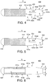
- Figure 4 shows a third embodiment of the present invention, in which the same or similar parts will be represented by elements labelled 4XX where elements of the first embodiment were labelled 1XX.
- the arrangement of Figure 4 is very similar to the arrangement of Figure 1 .
- partition member 436 in the form of an L-plate extending from, for example, wall 432a of housing 430 at a position rearward of perforate opening 431a.
- Partition member 432a extends the full height of housing 430 in directions perpendicular to the plane of the paper, so as to divide void 434 into portions 434d and 434e, which communicate through aperture 434f defined between partition member 432a and trailing end wall 433c.
- Void 434e communicates with perforate openings 431a and 431b, while partition member 432a closes one end of void 434d.
- partition member 432a can be modified, and partition member 432a can be provided, for example, as a single plate extending from, e.g., wall 332a at an angle rearward towards trailing end wall 433c, or as a curved plate provided extending inwardly from wall 432a and curving towards tail-end wall 433c.
- Figure 5 shows a fourth embodiment of the present invention, which combines the features of the second and third embodiments, having a partition member and also a porous-absorbing material positioned in the cavity.
- the same or similar parts are represented by elements labelled 5XX where elements of the second embodiment were labelled 3XX and elements of the third embodiment were labelled 4XX.
- Figure 6 shows a fifth embodiment of the present invention, in which the same or similar parts are represented by elements labelled 6XX where elements of the first embodiment were labelled 1XX.
- Sound suppression apparatus 600 shown in Figure 6 is similar to the first embodiment shown in Figure 1 .
- the resistive sound-absorbing material is not provided as a single uniform mass, but rather is provided in the form of two plates 610a, 610b provided on either side of the sound suppression apparatus 600 relative to a direction of gas flow and supported by a supporting member 611.
- Plates 610a have sufficient thickness d to absorb a desirable range of frequencies, and are supported by supporting member 611.
- Supporting member 611 may be a hollow member providing opposite surfaces 611a and 612a against which the resistive sound-absorbing material is provided.
- supporting member 611 may itself be formed of a strong yet lightweight mesh material, cellular material or scaffolding which will support the resistive sound-absorbing material 610a and 610b without adding significant weight to the structure.
- Such a configuration may be preferred when the sound suppression apparatus is required to have large overall dimensions relative to the thickness of resistive sound-absorbing material which is to be provided in the resistive sound-absorbing element.
- Figure 7 shows a sixth embodiment of the present invention based on the fifth embodiment of Figure 6 .
- sound suppression apparatus 700 is provided with a reactive sound-attenuating element, the housing of which extends into the space occupied by supporting member 611 in Figure 6 .
- Void 734 therefore extends towards cap 720 as far as end wall 732d.
- Perforated portions 731a and 731b, which allow void 734 to communicate with the surface of the sound suppression apparatus, are provided at the same position as they are in Figure 1 . However, in this configuration they may also be moved rearwardly along the direction of gas flow G so as to be positioned, for example, on walls 733a and 733b of the tapered portion 733 of housing 730.
- a further partition can be provided to the housing 730 between walls 732d and 732c as desired to adjust the characteristic frequency associated with void 734.
- Figure 7 allows a very large resonant cavity to be achieved for allowing very low frequencies to interact with the resonant cavity of the sound suppression apparatus whilst maintaining the overall length of the apparatus.
- Figure 8 shows a seventh embodiment of the sound suppression apparatus, being a modified form of the sixth embodiment of Figure 7 , in which the same or similar parts are represented by elements labelled 8XX where elements of the sixth embodiment were labelled 7XX.
- the seventh embodiment of Figure 8 differs from the sixth embodiment shown in Figure 7 in which wall 732d separating void 734 from the space enclosed by leading end cap 720 is removed, and the entire length of sound suppression apparatus 800 is available for use as a resonant cavity.
- Figure 9 shows an eighth embodiment of the present invention, being a modified form of the fifth embodiment of Figure 6 , in which the same or similar parts are represented by elements labelled 9XX where elements of the fifth embodiment were labelled 6XX.
- the eighth embodiment of Figure 9 differs from the fifth embodiment of Figure 6 in that that the wall separating the end cap from the space enclosed by supporting member 611 in Figure 6 is removed and end cap 920 in Figure 9 is perforated so as to allow the void 921 defined inside supporting member 912 to be used as the resonant chamber of a further reactive sound-attenuating element.
- the resonant chamber of this further reactive sound-attenuating element is then defined by walls 912a, 912b, 912c and end cap 920, and the dimensions of the void can be chosen to select the characteristic frequency.
- Figure 9 thus provides two reactive sound-attenuating elements, and taking into account also housing 930 defining enclosed space 934 communicating with the outer surface of the sound suppression apparatus 900 via perforate openings 931a and 931b.
- the position of wall 912c can be adjusted to adjust the characteristic frequency associated with the end-cap resonator.
- a further partition can be provided to the housing 930 downstream of wall 912c as desired to adjust the characteristic frequency associated with void 934.
- Figure 10 shows a ninth embodiment, in which the same or similar parts are represented by elements labelled 10XX where elements of the first embodiment were labelled 1XX.
- the ninth embodiment of Figure 10 no end cap is provided, but instead porous material 1010 extends to the front end of sound suppression apparatus 100 so as to meet the incident gas flow G. In this configuration, a larger surface area is available for interaction with the incident gas flow.
- the configuration of Figure 10 may be less appropriate when the resistive sound-absorbing material 1010 is particularly susceptible to erosion by the incident gas stream. In such situations, when using the configuration of Figure 10 , it may be necessary to replace porous material 1010 more frequently than if a cap portion were provided.
- FIG. 11 A tenth embodiment of the present invention is shown in Figure 11 based on the third embodiment of Figure 4 .
- the embodiment of Figure 11 in which the same or similar parts are represented by elements labelled 11XX where elements of the third embodiment are labelled 4XX, includes a partition member 1136 dividing void 1134 which is enclosed by housing 1130 into two sections.
- the embodiment of Figure 11 differs from the arrangement of Figure 4 in that no straight portion bounded by straight walls 432a and 432b is present. Rather, tapered walls 1133a and 1133b extend rearwardly from perforate openings 1131a and 1131b.
- the configuration of Figure 11 may be particularly preferred when the sound suppression apparatus is relatively short and there is a need to optimise the gas flow past the silencer for minimum disruption.
- perforate openings 1131a and 1131b may be provided in the tapered walls, such that the entire housing portion is tapered.
- Figure 12 shows an eleventh embodiment of the present invention similar to the embodiment of Figure 4 , in which the same or similar parts are represented by elements labelled 12XX where elements of the third embodiment are labelled 4XX, but in which an alternate configuration of partition member 1236 is used.
- partition member 1236 extends toward 1233c as a plate perpendicular to the plane of the page so as to divide void 1234 contained within housing 1230 into two intercommunicating voids.
- Partition structure 1236 generally has the form of a plate, and preferably extends the entire height of sound suppression apparatus 1200 in directions perpendicular to the plane of the page.
- the configuration of Figure 12 has a similar effect to the configuration of Figure 4 , in that the resonant length of void 1234 is increased and the characteristic frequency is decreased.
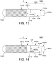
- FIG. 13 A twelfth embodiment of the present invention is shown in Figure 13 , in which the same or similar parts are represented by elements labelled 13XX where elements of the third embodiment are labelled 4XX.
- Sound suppression apparatus shown in Figure 13 is similar to sound suppression apparatus 400 shown in Figure 4 except that the resonant void 1334 defined within housing 1330 is shortened by an additional partition member 1333e, which is arranged extending above and below the plane of the page and across the cross-sectional width of void 1336 so as to shorten the resonant cavity provided by the void, relative to the length of the resonant cavity were partition member 1333e not present.
- Figure 13 permits the resonant frequency of the cavity to be increased without disrupting the aerodynamic advantages afforded by tapered housing section 1330.
- Partition member 1333e can be placed as far forward as is desired toward perforate openings 1331a and 1331b.
- Such a configuration can be especially adopted in configurations in which the tapered portion converges to a point in order to preserve resonance characteristics provided by a trailing end wall as set out above.
- the further void provided between partition 1333e and trailing end wall 1333c can be used to provide a further reactive sound-attenuating element of the type shown in any of the preceding embodiments.
- Such a configuration having a further resonator can, in a similar manner to the eighth embodiment shown in Figure 9 , allow two frequencies to be addressed by two appropriately-tuned cavity resonators.
- Figure 14 shows a thirteenth embodiment of the present invention, having a further modified resonator configuration within housing 1430.
- the configuration of Figure 14 provides two L-shaped partition members 1434a, 1434b, one extending inwardly from wall 1432a and then extending rearwardly towards trailing end wall 1433c, the other extending inwardly from tapered wall 1433b towards tapered wall 1433a and then extending forwardly towards end wall 1432v.
- the effect of providing two partition members as shown in Figure 14 is to lengthen the resonant path in resonant cavity 1434, thus allowing very low frequencies to be addressed.
- partition members 1436a and 1436b are provided as L-plate members extending the full height of the sound suppression apparatus 1400 perpendicular to the plane of the page, other forms of resonator are possible, as one skilled in the art would appreciate.
- Figures 1-14 illustrate many variants and configurations of hybrid sound suppression apparatuses having a combination of resistive sound-absorbing elements and reactive sound-attenuating elements and which suitable for installation inside a gas transport duct.
- other reactive sound absorbing structure such as a Helmholtz resonator, a side-channel, or an expansion region can be provided by the housing as the reactive sound absorbing element.
- the various features described in each above embodiment can be combined, without limitation, to achieve the desired suppression of one or more predetermined characteristic frequencies as well as a broadband suppression.
- housing 430 is defined by leading edge wall 432c, trailing edge wall 433c, first straight side wall 432a and second straight side wall 432b extending rearwardly from the side edges of leading edge wall 432c, and taper walls 433a and 433b respectively extending from a trailing edge end of walls 432a and 432b and terminating at trailing edge wall 433c.
- the top and bottom of housing 430 here are shown as top plate 437a, having a shape matching the plan profile of housing 430, and bottom plate 437a, having a corresponding profile.
- L-shaped partition member 436 is provided extending from side wall 432a.
- Perforate portions 431a and 431b are provided as separate plate elements arranged within or to overlie corresponding openings at a leading edge end of straight wall portions 432a and 432b which communicate between the outer surface of housing 430 and void 434 defined within housing 430.
- the configuration shown in Figure 15 is suitable for use as a splitter in an appropriately-sized duct having a cross-sectional span similar to height H of the sound suppression apparatus shown in Figure 15 , or alternatively as a brick silencer in a duct having height greater than height H.
- housing 430 shown in Figure 15 is intended to be used in a splitter configuration
- top and bottom plates 437a and 437b can be omitted, as the walls of the duct against which housing 430a is to be arranged may adequately seal the void 434, for example by welds.
- top and bottom plates 437a and 437b can be provided to improve structural integrity, to make installation easier, and to allow for thermal expansion of the duct cross-section.
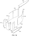
- Figure 16 shows a construction process for the housing 43 shown in Figure 15 .
- Leading edge wall 432c is formed from bent sheet metal, such as steel sheet, together with the leading edge portions of walls 432b in which perforate portions 431a and 431b are arranged.
- Trailing edge portions of wall 432a are also formed from bent sheet metal together with tapered portion wall 433a and one half of trailing edge wall 433c.
- a corresponding portion is made of bent sheet metal comprising the trailing edge portion of wall 432b together with taper wall 433b and the other end of trailing edge wall 433e.
- Top and bottom plates 437a and 437b are formed of sheet metal with perpendicularly-formed tabs projecting inwards for welding with respective wall portions, so as to form a rigid and substantially air-tight enclosure, except for the permitted communication of air through porous panels 431a and 431b.
- Figure 17 shows an alternative configuration of the arrangement of Figure 15 , which is particularly suitable for use in a brick configuration.
- additional perforated panels 432c and 432d are provided in top and bottom plate 437a and 437b while trailing edge section 433 is formed as a truncated square-based pyramid with walls 433a, 433b, 433d and 433e converging at trailing end wall 433c.
- a configuration of Figure 17 therefore has substantially symmetric external configuration with reflection symmetry about orthogonal planes (vertical and horizontal planes) including the longitudinal axis, such that the configuration of Figure 17 has a rectangular profile when viewed from an oncoming direction of gas.
- the sound suppression apparatuses of the present invention may be installed in ducts D in a variety of configurations, as shown in Figure 19 .
- Figure 19 shows a series of views in the gas transport direction along a variety of different types of ducts, having a variety of different sound suppression apparatus installed therein, the various sound suppression apparatus corresponding to embodiments and variants described above.
- Configuration A of Figure 19 shows two splitters arranged in a square duct.
- Configuration B of Figure 19 shows four sound suppression apparatuses in brick form arranged in a square duct.
- Configuration C shows a circular brick (or pod) sound suppression apparatus arranged in a circular duct.
- Configuration D shows two sound suppression apparatuses in a splitter configuration arranged in a circular duct.
- Configuration E shows nine sound suppression apparatuses, five of which are of square brick configuration and four of which are of triangular brick configuration arranged within a round duct. Many other variants may be considered by the skilled person when putting the present invention into practice.
- the sound suppression apparatuses should be arranged in correspondence with a propagation mode pattern for a frequency which the sound-suppression apparatuses are configured to attenuate.
- the half-wavelength of the sound wave when the half-wavelength of the sound wave is greater than the minimum cross-sectional dimension of the duct, the sound waves propagate in the duct as a plane wave.
- the half-wavelength of the sound wave decreases and it is possible for higher-order modes than the plane wave to propagate in the duct.
- Such higher-order modes propagate with a wavefront which has non-uniform pressure distributions in a plane perpendicular to the direction of propagation.
- Each higher-order mode has a particular cut-on frequency, which will depend on the dimensions and geometry of the duct.
- Figure 20A shows the pressure distribution across the wave-front of a particular higher-order mode of a rectangular duct, having 4 pressure antinodes arranged across the width of the duct and 3 pressure antinodes arranged across the height of the duct.
- the arrows show the pressure antinodes, while the edges of the boxes containing the arrows define the pressure nodes.
- the acoustic energy can be considered to transmit along the length of the duct through the centre of each box.
- the reactive sound-suppression elements can be provided so as to interact effectively with the propagating higher-order modes.
- the reactive sound-suppression elements can be provided so as to interact effectively with the propagating higher-order modes where many of the anti-nodes preferentially propagate away from the duct walls.
- the sound-suppression apparatuses are arranged in the duct to correspond to a higher-order mode pressure antinode distribution of a particular frequency of interest, which is a frequency which a sound-attenuation element of each sound-suppression apparatus is configured to attenuate.
- the sound-suppression apparatuses are arranged to have an equal spacing across the duct.
- the sound-suppression apparatuses can be arranged in two perpendicular dimensions across the duct. In other configurations, the sound-suppression apparatuses can be elongated in one dimension across the duct, and can comprise more than one resonant cavity to interact with a corresponding number of antinodes of the higher-order mode which is arranged in that dimension.
- Each sound suppression apparatus can interact effectively with higher order modes which have reactive sound-attenuating element openings near to the locations of all pressure antinodes for the higher order mode. So, for example, in one-dimension, a single sound suppression apparatus centred in the duct, openings can be located close to, at most, 2 anti-nodes. Therefore, it can control higher order modes up to the second order effectively. Using two sound suppression apparatus' spaced across the duct, openings can be located to, at most, 4 anti-nodes. Therefore, higher order modes up to the fourth order can be effectively controlled.
- This approach can be generalised to two-dimensional arrangements of the sound suppression apparatuses and the respective reactive sound-attenuating elements.
- Figure 20B shows sound suppression apparatus being embodiments of the present invention in the form of brick baffles, with each sound suppression apparatus being placed at each antinodal position of the propagating higher-order mode of Figure 20A , the reactive sound-attenuating element of the sound suppression apparatus then being appropriately tuned to attenuate that frequency, for example being a harmonic of a resonant cavity incorporated in each sound suppression apparatus.
- Such a configuration can effectively attenuate frequencies that allow the mode shown in Figure 20A to propagate.
- such a configuration can also attenuate other higher-order modes, including all relatively lower-order modes than that shown in Figure 20A , provided that such modes also correspond to a harmonic of the resonant cavity.
- each sound suppression apparatus can be provided in the form of, for example, vertical splitter baffles having internal plates dividing the resonator void into plural voids arranged, for example, vertically, so as to provide an arrangement of reactive sound-attenuating elements which corresponds to vertical mode pattern in the duct.
- sound suppression apparatuses in the form of, for example, vertical splitter baffles could then be arranged, for example, horizontally across the duct to correspond to a desired mode pattern in the duct.
- the term vertical is used to provide a convenient reference frame, and the baffles may be arranged at any appropriate orientation within the duct. Where the duct is rectangular, arrangement of the splitter baffles perpendicular to one opposing pair of walls of the duct and parallel to the other opposing pair of walls can be especially effective in controlling the higher order modes as described above.
- any sound suppression apparatuses arranged between the sound suppression apparatuses nearest to the walls of the duct are arranged at a spacing of one wavelength of the highest frequency targeted for control by the reactive element.
- One approach to the arrangement of the sound-suppression apparatuses according to the present disclosure is to identify the highest frequency which the reactive element is desired to attenuate and calculate the corresponding highest cut-on mode at this frequency.
- the sound-suppression apparatuses having reactive sound-attenuating elements which are tuned to attenuate that mode, for example, as a fundamental or harmonic mode of the reactive sound-attenuating element, are then arranged within the duct in a spatial pattern which corresponds to that mode. At least that frequency, and all frequencies below, will then efficiently be attenuated.
- the cut-on frequency for the propagation of higher order modes is typically at around 100 Hz.
- the resonator would attenuate frequencies at 31 Hz and each harmonic multiple of 31 Hz, but would do so inefficiently at the harmonics above 100 Hz, since these harmonics will be above the cut-on frequency for higher order modes.
- the sound suppression apparatuses may be arranged at a maximum amplitude or anti-nodal point of a resonant mode pattern formed along the length of the duct for the frequency of interest.
- the opening of each respective reactive sound-suppression element may be arranged at or near a pressure anti-nodal point of the frequency of interest along the length of the duct.
- the opening of the reactive sound-suppression elements may be arranged at a pressure antinode of the wavelength of interest relative to this node, for example, at odd multiples of the wavelength associated with the frequency of interest from the open end of the duct.
- two or more sound suppression apparatuses may be placed within a duct, the reactive sound-attenuating element of each sound suppression apparatus being tuned to absorb a different resonant frequency.
- two sound suppression apparatuses 100 in accordance with a first embodiment of the present invention, shown in Figure 1 are provided in parallel.
- One of the sound absorbers is provided with a longer resonant cavity by extending the housing relatively more rearward than the other. This allows the sound suppression apparatuses to be tuned to different frequencies, thereby achieving a broader range of frequency suppression overall.
- the configuration as shown in Figure B has the same intent as the configuration of Figure A, except that the first sound absorbing apparatus 400 is in accordance with Figure 4 , while the second sound absorbing apparatus 1300 is in accordance with Figure 13 .
- the apparatus 400 in accordance with Figure 13 has a second partition member which shortens the resonant cavity. Therefore, for a sound-absorbing apparatus having the same overall dimensions, the sound suppression apparatus 1300 shown in configuration B of Figure 21 has a relatively higher frequency than sound suppression apparatus 400 shown in configuration B of Figure 21 .
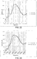
- Figure 22 shows a comparison of sound suppression ability between a duct containing a normal dissipative baffle as shown in Figure 25 compared with a sound suppression apparatus as shown in Figure 4 having the resonant cavity tuned for 125 Hz.
- the resonator provides an additional resonant absorbent peak at 125 Hz, but also contributes to a general enhancement of the broad-band performance between 200 and 3000 Hz, resulting in an overall much-improved performance without significant additional disadvantageous effect on the airflow past the baffle.
- Figure 23 shows a comparison between a pair of normal dissipative baffle as shown in Figure 25 with a pair of sound suppression apparatuses in accordance with Figure 4 , one of which being tuned to a characteristic frequency of 175 Hz, the other being tuned to a characteristic frequency of 250 Hz, one-third octave apart from the 175 Hz resonator.
- an overall significantly enhanced broad-band performance is achieved as compared with the conventional dissipative baffles.
- both resistive and reactive sound-attenuating elements are provided in a single sound suppression apparatus as herein disclosed, both resistive and reactive sound-attenuating elements are able to interact with the gas stream passing the outer surface of the apparatus.
- the resistive and reactive sound-attenuating elements provide interacting effects on this gas stream such that a sound suppression performance which exceeds the individual contributions expected from resistive or reactive elements alone can be obtained.
- reactive elements which are relatively more efficient at reducing specific low frequencies, may operate less efficiently on a gas stream containing sound waves which are non-planar and which have a relatively greater higher-order mode content.
- the provision of a resistive element which more readily attenuates higher-order modes than the fundamental, can reduce the higher-order modes propagating in the duct and can therefore allow the reactive element to operate in relatively more ideal conditions.
- Such an effect is especially achievable when the reactive element is located downstream in the direction of gas flow relative to the location of the resistive element, since when the reactive element is placed downstream of the resistive element, the reactive element can generate a local pressure minimum and hence a local velocity maximum. This local velocity maximum is believed to increase the damping of the dissipative elements.
- the aerodynamic properties of the apparatus as a whole can be selected so as to provide enhanced sound suppression performance while minimising unwanted disruption to a passing gas stream.
- Such a configuration can further enhance the synergistic effect of the reactive and resistive elements, since no disruptive element is provided in the gas flow between the reactive and resistive elements. Additionally, such a configuration can avoid unnecessarily increasing flow speeds in the duct and can therefore avoid additional flow noise generation and undesired pressure drop.
- the higher harmonics of the reactive elements can have an appreciable effect in improving the overall attenuation in a mid-frequency range low-frequency attenuation associated with the reactive elements.
- the gas is air at standard temperature and pressure, namely a temperature of 25°C and a pressure of 100kPa, flowing at 50 m/s.
- the present disclosure can be applied to flows of other gases under other conditions, without limitation.
- the ducts can be considered to have a maximum cross-sectional dimension between 1m to 9m, although the present disclosure can be applied to other duct configurations, without limitation.
- the embodiments of the present invention can be made relatively straightforward to fit to existing ducts and can be manufactured to correspond to standardised duct dimensions for installation into new projects without increasing the dimensions, weight or complexity of the duct itself. Furthermore, where changes in equipment performance, the replacement of equipment, or a change in regulatory requirements require a change in the sound suppression capabilities of existing ducting, the embodiments of the present invention can provide an effective retro-fitted solution.
- the embodiments of the present invention can be manufactured so as to occupy a volume and provide a flow resistance not significantly greater than that of a resistive baffle, while providing improved sound suppression performance.
Landscapes
- Engineering & Computer Science (AREA)
- General Engineering & Computer Science (AREA)
- Mechanical Engineering (AREA)
- Combustion & Propulsion (AREA)
- Chemical & Material Sciences (AREA)
- Physics & Mathematics (AREA)
- Acoustics & Sound (AREA)
- Multimedia (AREA)
- Aviation & Aerospace Engineering (AREA)
- Fluid Mechanics (AREA)
- Soundproofing, Sound Blocking, And Sound Damping (AREA)
- Duct Arrangements (AREA)
- Pipe Accessories (AREA)
- Exhaust Silencers (AREA)
Description
- The present invention relates to a sound suppression apparatus, and particularly to a sound suppression apparatus suitable for installation inside a gas transport duct. The present invention also provides gas transport ducts having sound suppression apparatuses in accordance with the invention arranged therein, and may be especially suitable for installation in intake or exhaust ducts of power generation equipment or in the oil and gas industries.
- Many industrial processes require the intake or exhaust of large quantities of gas. Such industrial processes include power generation, heating, ventilation, and air conditioning (HVAC), forced-air cooling and fume extraction, as well as in processes, especially combustion processes, of the oil and gas industries.
- Transport of such gas is usually achieved by flowing the gas through ducting of appropriate dimension and construction from the source of the gas to a location at where it is required to be exhausted or used. In the case of intake of gas, for example atmospheric air, the gas is transported from an intake vent, possibly provided with suitable filtering means, to a location at which the gas is used or required, via a suitable intake duct. In the case where gas is to be exhausted, the gas is transported from the location at which it is produced, possibly via various treatment processes such as filtering and scrubbing, to an exhaust vent at which the gas is to be exhausted, via an exhaust duct.
- Firstly, the processes which use or generate the gas, such as combustion processes, may generate large quantities of undesirable noise. Further, where the rate of transport of gas is to be high, the transport of gas can be associated with the generation of undesirable noise. Also, the means by which the gas is drawn into or drawn out of the location where the gas is produced or consumed, for example fans and the like, can generate substantial amounts of undesirable noise themselves. Transport of this noise via the gas in the duct to the surrounding environment is undesirable. Particularly, health, safety and environmental considerations, as well as applicable laws and regulations, often restrict the noise level to which plant operators, local workers, local residents or wildlife is exposed. Therefore, there is a need to provide reliable means of reducing the noise level associated with gas intake and gas exhaust processes.
- It is known in the art to provide gas transport ducts with elements which are able to absorb a portion of the acoustic energy present in the gas flow through the duct, thereby to reduce the noise level associated with the gas transport process. Such elements are often referred to as sound suppression elements.
- One example of a technique for sound suppression in a gas transport duct includes the positioning of resistive sound-absorbing elements in the duct. These elements are made of a material which presents resistance to the propagation of the sound wave, for example by being composed of a mass of fibres or having a large number of inter-connected pores. Interaction of the sound wave with this material absorbs acoustic energy from the sound wave and converts it to another form of energy, typically heat. Portions, such as sheets, of such resistive sound-absorbing material may be applied to the inner walls of the duct, so as to absorb acoustic energy from gas passing through the duct. Often, the materials used as resistive sound-absorbing materials, such as rock wool or glass wool, are relatively fragile and can be eroded by the passage of high velocity gas, especially passing at elevated temperatures. Therefore, it is known to secure the resistive sound-absorbing material against the wall using a layer of perforated material, such as steel mesh, which is more resistant to erosion by the flow of gas. Such a configuration is disclosed in British patent
application publication GB 2 122 256 A - Resistive sound-absorbing material typically absorbs efficiently only frequencies at which the thickness of the absorbent material is greater than a quarter wavelength of the sound. For frequencies below this limit, the sound-absorption process is far less efficient. Further, the effectiveness of the sound-absorbing process increases with the proportion of the internal surface of the duct exposed to the gas flow which is provided with resistive sound-absorbing material, as well as the length of duct over which the gas flow can interact with the resistive sound-absorbing material. Therefore, in order to suppress across a broad frequency band efficiently, a large thickness of resistive sound-absorbing material must be placed such that a relatively large proportion of the wall area is provided with the resistive sound-absorbing material. This tends to decrease the internal cross-sectional area of the duct.
- However, as the internal cross-sectional area of the duct is decreased, the gas flow velocity increases for a given gas flow rate. Increasing the internal cross-sectional area of the duct to counter this effect reduces the sound absorption performance. Therefore, in order successfully to use resistive sound-absorbing material to achieve adequate sound suppression across a broad range of frequencies without decreasing the cross-section of the duct available for gas flow, the outer dimensions of the duct must, both in terms of cross-section and in terms of length, be increased. However, such an approach results in larger, heavier and correspondingly more expensive gas handling equipment.
- In some circumstances, it is known to install resistive baffles inside a gas flow duct. Such baffles are installed within the cross-sectional flow path of the duct, and can either run fully across a cross-sectional dimension of the duct, essentially splitting the duct into two flow passages on either side of the baffle, or can be provided with a relatively smaller length than the cross-section of the duct into which they are installed so as to be arranged in a central space of the duct. The former is known as a splitter baffle, the latter is known as a brick baffle, sometimes also known as a bar baffle. The general plan view of such a resistive baffle, whether a brick baffle or a splitter baffle, is shown in
Figure 25 . - In
Figure 25 ,baffle 2500 provides a mass of resistive sound-absorbingmaterial 2510 of sufficient thickness, length and cross-sectional area to achieve a desired broadband reduction of unwanted acoustic frequencies. Sincebaffle 2500 is to be placed in the gas flow inside the duct,baffle 2500 is also provided with acap portion 2520 arranged to face the oncoming gas flow, and being configured to have a convex surface facing the oncoming gas flow so as smoothly to divert the gas flow to either side of the baffle.Cap portion 2520, by diverting the gas flow to either side ofbaffle 2500, functions firstly to reduce the impact of the baffle on smooth gas flow through the duct and secondly to reduce the possibility that the resistive sound-absorbingmaterial 2510 will be eroded by the oncoming gas.Cap portion 2520, in the case of a splitter baffle, may have a constant cross-section running the entire vertical height of the baffle, which is perpendicular to the plane of the page. In some configurations,cap portion 2520 may be substantially semicircular, and may smoothly join with essentially parallel sides of the resistive sound-absorbingmaterial 2510. In some configurations, the mass of resistive sound-absorbing material is shielded by a screening material such as a mesh or fabric, which may define part of the outer surface of the baffle. In such a configuration, the screening material may be considered to form part of the resistive sound-absorbing material. - In the configuration of a brick silencer,
Figure 25 may represent not only the plan view, but also the elevation view, andcap portion 2520 may be in the form of a hemispherical dome, and again may be formed to join smoothly with parallel circumferential sides of resistive sound-absorbingmaterial 2510 in the case where thebaffle 2500 has an overall circular cross-section viewed in the direction of gas travel. In other configurations,baffle 2500 may have a generally square or rectangular configuration in the direction of gas travel, and the shape ofcap portion 2520 may be appropriately selected. - At the other end of
baffle 2500 tocap portion 2520, afairing portion 2530 is provided to reduce further the impact ofbaffle 2500 on the smooth flow of gas through the duct. The fairing portion is constructed with a slight taper relative to the parallel walls of the resistive sound-absorbingmaterial 2510 for reducing the impact on the flow of gas past the baffle. - An alternative technique for sound suppression to the resistive sound-absorbing element is the so-called reactive, sometimes termed reflective, sound-attenuating element. Such reactive sound-attenuating elements involve passing the gas flow past a geometrical feature such as a depression, channel or cavity, the geometry of which causes the propagation of a sound wave at a characteristic frequency in opposite direction and/or in opposite phase to the sound waves propagating in the transported gas. This can be achieved in one approach by changing the acoustic impedance of the gas flow duct, for example by expanding the cross-sectional area, so as to generate a reflected wave at the characteristic frequency in counter-phase to the incoming acoustic energy. Alternatively, this can be thought of as altering the acoustic resistance coupled to the sound-wave radiating source.
- Alternatively, the gas flow may be split into two gas flows, travelling along two paths having different lengths, which are re-combined so that the interference of the sound waves at the exit of each path results in cancellation of the acoustic energy. Here, the path-length difference defines the characteristic frequency of the reactive sound-attenuating element. Further alternatively, a resonant cavity may be coupled to the flow path, either directly or via a connecting channel, the dimensions and geometry of the resonant cavity, as well as the area and length of the tube communicating between the resonant cavity and the flow path, being selected so that the waves generated in the resonant cavity when excited by the incident sound waves cancel out a desired portion of the noise in the gas flow. Such a resonant cavity can be thought of also as a trap for the acoustic energy in the gas flow, wherein the resonant mode or modes of the cavity, being a characteristic frequency of the resonator, absorb desired portions of the acoustic energy spectrum. The characteristic frequency may be a fundamental frequency of the resonator, or may be a harmonic frequency of the resonator.
- One well-known configuration of resonant sound-absorber is the Helmholtz resonator, which consists of a large chamber connected by a narrow tube to the gas flow path. The characteristic frequency is defined by the geometry of the chamber. Another form of resonator is the quarter-wavelength resonator, which consists of a closed pipe extending from the gas flow path and having a length of approximately one quarter the intended wavelength of the characteristic frequency to be suppressed. A variant of the quarter-wavelength resonator is the so-called half-wavelength resonator, consisting of a pipe which, rather than having straight sides, tapers to a point and has a length of half the wavelength of the characteristic frequency which is intended to be suppressed. Further, there is the eighth-wavelength resonator, consisting of a pipe similar to the quarter wavelength resonator, but which is divided into an open-ended portion and a closed-ended portion which communicate with each other, the depth of which from the channel is one-eighth of the wavelength of the characteristic frequency which is to be suppressed.
- Examples of each of these reactive sound-absorber types are shown in
Figure 24 . Configuration A shown inFigure 24 is the so-called impedance mismatch or expansion resonator, where the diameter of the duct is expanded to produce a reflection wave. Sometimes, perforated material covers the expansion region to maintain stable gas flow past the expansion region. Configuration B shown inFigure 24 is a Helmholtz resonator, wherein a resonant cavity is connected by a short tube to the gas flow duct. Configuration C shown inFigure 24 is the quarter-wave resonator, in the form of a short, closed pipe. Configuration D shown inFigure 24 is the half-wave resonator, in the form of a tapered, closed pipe. Configuration E shown inFigure 24 is the eighth-wave resonator, in the form of a divided, closed pipe. Configuration F shown inFigure 24 is a side-channel resonator, sometimes termed the Herschel-Quincke tube, having the form of a short side-channel having a desired path length difference compared with the gas flow in the duct. - Although reactive sound-attenuating elements can be effective at suppressing a well-defined frequency and its harmonics, reactive sound- attenuating elements lack the broad-band sound-absorbing properties of the resistive absorber. Furthermore, providing such sound- attenuating elements in the walls of a duct again entails increasing the duct dimensions for a given desired gas flow rate and requires costly engineering of the walls of the duct to provide the desired resonant sound-absorbers at appropriate locations in the duct. Finally, providing such sound-attenuating elements in the walls of a duct is ineffective in suppressing higher frequencies which propagate in the duct at higher-order modes of the duct, since the acoustic energy associated with such frequencies propagates along the duct in mode patterns which are distant from, and thus interact less, with the walls of the duct.
- It has therefore been proposed, in International patent application publication pamphlet
WO 98/27321 A - Furthermore, since the frequency spectrum associated with a gas transport duct results from a combination of the rate at which gas is transported along the duct, the gas-producing or gas-consuming equipment which is connected to the duct, the presence of intermediate gas treatment units such as filters, and the length and geometry of the duct itself, the provision of reactive and resistive sound-absorbers as part of the duct requires complex and expensive custom engineering work in designing the duct to meet the specific requirements of the project.
- Noise-attenuating splitters having portions filled with resistive material and portions left empty to provide resonant chambers are disclosed in
US 3,033,307 andUS 4,260,037 . - Despite the above-proposed techniques for control over unwanted noise in gas transport ducts, there is a need for sound suppression apparatus which is able to suppress a broad range of unwanted frequencies, for example high levels of targeted low-frequency control as well as good broadband performance, at high efficiency and which is cost-effective to manufacture and install.
- According to a first aspect of the present invention, there is provided a sound suppression apparatus as recited in claim 1.
- By providing such a hybrid sound suppression apparatus, both resistive and reactive sound-attenuating elements are able to interact with a gas stream passing the outer surface of the apparatus and a sound suppression performance which exceeds the individual contributions expected from resistive or reactive elements alone can thereby be obtained. Further, by providing such an apparatus, the resistive and reactive elements interact with the gas stream via a common external surface of the apparatus, the aerodynamic properties of the apparatus as a whole can be selected so as to provide enhanced sound suppression performance while minimising unwanted disruption to a passing gas stream.
- In some embodiments of the first aspect, the housing extends from the resistive sound-absorbing element.
In some embodiments of the first aspect, the outer surface of the sound suppression apparatus has reflection symmetry about a first plane including the longitudinal direction, the resistive sound-absorbing element provides a resistive sound-absorbing surface on both sides of the first plane, and the housing provides a reactive sound-attenuating element communicating with an outer surface of the housing (x1 at least one side, optionally both sides, of the first plane. - In some embodiments of the first aspect, the outer surface of the sound suppression apparatus has symmetry about a second plane including the longitudinal direction and being perpendicular to the first plane, the resistive sound-absorbing element provides a resistive sound-absorbing surface on both sides of the second plane, and the housing provides a reactive sound-attenuating element communicating with an outer surface of the housing on at least one side, optionally both sides, both sides of the second plane.
- In some embodiments of the first aspect, the resistive sound absorbing element consists of a mass of sound-absorbing material. In some embodiments, the mass of sound-absorbing material is shielded by a screening material such as a mesh or fabric.
- In some embodiments of the first aspect, the resistive sound absorbing element comprises at least one layer of sound-absorbing material supported by a supporting member, the supporting member optionally being provided by part of the housing.
- In some embodiments of the first aspect, the reactive sound-attenuating element comprises a cavity of the housing.
- In some embodiments of the first aspect, the opening of the housing is provided with a perforate portion arranged to cover or lie within the opening.
- In some embodiments of the first aspect, the outer surface of the housing comprises the perforate portion.
- In some embodiments of the first aspect, the cavity of the housing is provided with a partition member for setting a characteristic frequency of the reactive sound-attenuating element to a predetermined value. Where the sound suppression apparatus is in the form of a splitter, being elongate in a vertical direction across the duct and relatively narrow in a perpendicular horizontal direction across the duct, such a partition member may be provided in the horizontal plane.
- In some embodiments of the first aspect, the partition member is arranged to divide the cavity into a closed-ended portion and an open-ended portion which communicate with each other, the open-ended portion communicating with the opening of the housing.
- In some embodiments of the first aspect, the partition member is an L-shaped plate.
- In some embodiments of the first aspect, the reactive sound-attenuating element comprises a plurality of cavities of the housing, each communicating with a respective opening of the housing.
- In some embodiments of the first aspect, the reactive sound-attenuating element comprises a cavity of the housing which communicates with a plurality of openings of the housing.
- In some embodiments of the first aspect, a cap portion is provided arranged at a first end of the sound suppression apparatus to provide a convex end surface to the sound suppression apparatus, the cap portion optionally being part of the housing.
- In some embodiments of the first aspect, the cap portion provides a curved end surface to the sound suppression apparatus.
- In some embodiments of the first aspect, the outer surface of the sound suppression apparatus is shaped to provide aerodynamic gas flow from a first end to a second end of the sound suppression apparatus.
- In some embodiments of the first aspect, the resistive sound-absorbing element comprises at least one of a porous, fibrous, foamed or granular sound-absorbing material.
- In some embodiments of the first aspect, the reactive sound-attenuating element is a resonant cavity.
- According to a second aspect of the present invention, there is provided a gas transport duct as recited in claim 12 below.
- In some embodiments of the second aspect, the at least one sound suppression apparatus is arranged in the passage so as to divide the passage into at least two sub-passages.
- In some embodiments of the second aspect, the at least one sound suppression apparatus comprises a plurality of sound suppression apparatuses and at least two of the sound suppression apparatuses are provided with respective reactive sound-attenuating elements having different characteristic frequencies.
- In some embodiments of the second aspect, the different characteristic frequencies are related by one-third of an octave.
- In some embodiments of the second aspect, the at least one sound suppression apparatus is arranged in the passage such that a plurality of reactive sound-attenuating elements are provided at positions across the passage which correspond to a higher-order propagating mode pattern of the passage and to a fundamental or harmonic characteristic frequency of the reactive sound-attenuating elements.
- Embodiments of the present invention may provide a sound suppression apparatus which is able to suppress a broad range of unwanted frequencies, for example high levels of targeted low-frequency control as well as good broadband performance, at high efficiency and which is cost-effective to manufacture and install.
- For a better understanding of the present invention, and to show how the same may be carried into effect, reference will be made, by way of example only, to the accompanying Drawings, in which:
-
Figure 1 shows a plan view of a sound suppression apparatus in accordance with a first embodiment of the present invention; -
Figure 2 shows a sound suppression apparatus as shown and described with reference toFigure 1 installed as a splitter baffle in a gas transport duct; -
Figure 3 shows a sound suppression apparatus in accordance with a second embodiment of the present invention; -
Figure 4 shows a sound suppression apparatus in accordance with a third embodiment of the present invention; -
Figure 5 shows a sound suppression apparatus in accordance with a fourth embodiment of the present invention; -
Figure 6 shows a sound suppression apparatus in accordance with a fifth embodiment of the present invention; -
Figure 7 shows a sound suppression apparatus in accordance with a sixth embodiment of the present invention; -
Figure 8 shows a sound suppression apparatus in accordance with a seventh embodiment of the present invention; -
Figure 9 shows a sound suppression apparatus in accordance with an eighth embodiment of the present invention; -
Figure 10 shows a sound suppression apparatus in accordance with a ninth embodiment of the present invention; -
Figure 11 shows a sound suppression apparatus in accordance with a tenth embodiment of the present invention; -
Figure 12 shows a sound suppression apparatus in accordance with an eleventh embodiment of the present invention; -
Figure 13 shows a sound suppression apparatus in accordance with a twelfth embodiment of the present invention; -
Figure 14 shows a sound suppression apparatus in accordance with a thirteenth embodiment of the present invention; -
Figure 15 shows an isometric view of the housing provided for the third embodiment; -
Figure 16 shows an exploded view of the housing provided for the third embodiment; -
Figure 17 shows an alternative configuration of the housing of the third embodiment, suitable for a brick configuration; -
Figure 18 shows an exploded view of the housing ofFigure 17 ; -
Figure 19 shows a range of options for installation of the sound suppression apparatuses being embodiments of the present invention into various forms of ducting; -
Figure 20A shows a possible higher order mode pattern associated with a rectangular duct; -
Figure 20B shows one appropriate placement of embodiments of the present invention suitable for the mode pattern shown inFigure 20A ; -
Figure 21 shows ways in which embodiments of the present invention may be combined in a duct to provide sound suppression at a broader range of frequencies; -
Figure 22 shows comparative test data comparing a resistive baffle configuration with a sound suppression apparatus in accordance with an embodiment of the present invention; -
Figure 23 shows comparative test data comparing a pair of resistive baffles with a pair of sound suppression apparatuses in accordance with an embodiment of the present invention being tuned at neighbouring third octaves; -
Figure 24 shows different types of reactive sound-attenuating elements as known in the art; and -
Figure 25 shows a cross-section through a known baffle configuration. - According to a first embodiment of the present invention, there is provided a sound suppression apparatus as shown in
Figure 1 . -
Figure 1 shows asound suppression apparatus 100 having a configuration similar to thebaffle 2500 ofFigure 25 . Where the configuration is the same or similar, no further detail will be given, and the reader is referred to the corresponding elements of thebaffle 2500 ofFigure 25 . - The
sound suppression apparatus 100 has a mass of resistive sound-absorbingmaterial 110 arranged between acap portion 120 in an upstream direction of gas flow G and ahousing 130 arranged in a downstream direction of gas flow G, in a similar manner asbaffle 2500 shown inFigure 25 . - As for
baffle 2500 inFigure 25 , in the cross-section shown inFigure 1 , the resistive sound-absorbing material has straight, generally parallel sides, to permit the gas to flow smoothly and aerodynamically past. Aerodynamic flow, as herein discussed, refers to substantially laminar flow in a direction of elongation of the sound suppression apparatus.Cap portion 120 is convex towards a direction of incident gas flow to allow the incident gas to flow smoothly and aerodynamically aroundsound suppression apparatus 100. The resistive sound-absorbingmaterial 110 may be, for example, a porous, fibrous, foamed or granular sound absorbing material. Suitable materials can include rock wool, glass wool, basalt wool or an artificial or natural porous ceramic such as a pumice. In other configurations,cap portion 120 may be square, square with rounded corners, triangular, conical or pyramidal. - However, in contrast to the configuration of
Figure 25 , where thebaffle 2500 ofFigure 25 has fairingportion 2530,sound suppression apparatus 100 hashousing 130 arranged downstream of the resistive sound-absorbingmaterial 110 in a gas-flow direction. Althoughhousing 130 has a similar function to fairing 2530, in thathousing 130 includes a taperedportion 133 to permit the gas flow to flow smoothly and aerodynamically downstream of thesound suppression apparatus 100,housing 130 also has astraight portion 132 connecting a downstream end of resistive sound-absorbingmaterial 110 withtaper portion 133.Housing 130, in alternative configurations, can have a generally square, square with rounded corners, triangular, conical or pyramidal configuration in cross-section when viewed from the direction of incident gas flow. - In
straight portion 132,perforate portions housing 130. Here, an opening is defined as a region of a surface through which gas can pass, either through a single continuous aperture or through a plurality of perforations. The perforations may, for example, provide an open area percentage in a perforate region of at least 20%, at least 30%, at most 80%, at most 70%, at most 60%, at most 50%, or at most 40%, optionally being in therange 10% to 80%, further optionally being in the range 20% to 60%, yet further optionally being in the range of 22% to 40% for an appropriate balance between acoustic transparency and effective guidance of flow. The perforations may be identical, for example polygonal or circular, or may have varying shapes and dimensions.Perforate portions housing 130, although in certain configurations the perforate portions may only extend a proportion of the entire height ofhousing 130, for example at least 30%, 40%, 50%, 60%, 70%, 80% or 90% the height ofhousing 130. Alternatively, the perforated portions may be restricted to at most 30%, 40%, 50%, 60%, 70%, 80% or 90% the height ofhousing 130. The perforate portions on each side ofhousing 130 can be continuous, or can be provided as discrete and separated perforate regions in the vertical direction. - In the cross-section shown in
Figure 1 ,housing 130 is bounded by anupstream end surface 132c,straight side walls taper side walls end surface 133c. Parallel and opposedstraight side walls straight portion 132, whiletaper side walls taper portion 133, together with trailingend surface 133c. - While trailing
end surface 133c is shown as being flat, this surface may be provided, for example, as an outwardly-convex surface or may be entirely absent in the case wheretaper side walls taper portion 133 may be selected partly based on aerodynamic considerations to suit the expected gas flows in the duct into which soundsuppression apparatus 100 is to be inserted. - In the present configuration,
sound suppression apparatus 100 has a generally symmetric form in the cross-sectional plane of the paper with reference to a plane of symmetry S, which extends perpendicular to the plane of the paper and contains the direction of gas flow G. By providing a generally symmetric profile, asymmetric aerodynamic forces and diversion of the gas flow are avoided, and therefore the impact on the gas flow is reduced. However, in some applications, asymmetric forms may be adopted in order, for example, to assist in a diversion of the gas flow in a particular direction, by means of an aerofoil-type profile. - In a first configuration, the embodiment of
Figure 1 is provided for use as a splitter, having an extent in the direction perpendicular to the plane of the page so as to match an internal cross-section of the duct into which thesound suppression apparatus 100 is intended to be installed. In such a configuration, the internal walls of the duct against which thesound suppression apparatus 100 is placed may define surfaces which enclosevoid 134, otherwise defined bywalls housing 130, respectively above and below the plane of the paper, to enclose void 134 otherwise enclosed bywalls housing 130. Such end walls may be mutually parallel and parallel to the plane of the page. - In a case where
sound suppression apparatus 100 extends perpendicular to the plane of the page so as to span an entire cross-sectional area of the duct into which it is installed,cap portion 120 and resistive sound-absorbingmaterial 110 may also extend across the total internal cross-sectional span of the duct in the same way ashousing 130. However, in some configurations, the resistive sound-absorbingmaterial 110 may only be provided to a proportion of the height of thesound suppression apparatus 100 spanning the duct, and plate regions may be provided in the cross-sectional direction of the duct on either side of the resistive sound-absorbing material to extend as far as the walls of the duct, as desired. -
Figure 2 shows an example of such one such configuration of the embodiment ofFigure 1 , shown in elevation and installed across an entire cross-sectional span X of a duct D, functioning as a splitter. Gas flow G, incident from the left-hand side ofFigure 2 , impinges oncap portion 120 and is split in directions above and below the page to pass either side ofsound suppression apparatus 100. - In an alternative configuration,
sound suppression apparatus 100 need not extend the full cross-sectional dimension X of the duct, and in such a case,housing 130 should be closed by appropriate top and bottom plates, such that thevoid 134 is enclosed on all sides. - In contrast to the
baffle 2500 shown inFigure 25 , by providinghousing 130 havinginternal void 134 communicating with an outer surface ofhousing 130 viaperforate portions sound suppression apparatus 100, a reactive sound-attenuating element is provided which acts to reduce the intensity of selected acoustic frequencies in the gas flow passing the sound suppression apparatus. In the configuration shown inFigure 1 , void 134 is essentially a closed space, being connected to the flowing gas byperforate portions upstream end surface 132c,straight side walls taper side walls end wall 133c. Void 134 acts as a resonator chamber, the characteristic frequency of which corresponds to the acoustic frequency to be reduced in the flowing gas. - In the present configuration, the size and shape of the perforated area on each side of the housing substantially corresponds to the cross-sectional area of
void 134 across a direction of sound propagation into the void. In the present configuration, this is the cross-sectional area ofvoid 134 taken across the direction of incident gas flow. Such a configuration can enhance coupling of the acoustic energy in the gas stream into the resonator defined by the void. - It is possible to alter the characteristic frequency at which void 134 acts by adjusting the geometry of
housing 130. For example, making the housing longer in a dimension from theupstream end surface 132c to trailingend wall 133c will tend to lower the resonant frequency. Adjusting the relative length oftaper portion 133 andstraight portion 132 as well as the taper angle of the taper portion will also adjust the tuning, and also the bandwidth of the resonant peak. Such adjustments are considered to be well within the scope of the person skilled in the art to achieve, based on straightforward experimentation and acoustic design. Particularly, a taper angle of 7.5° toward a trailing wall provides a resonant structure having a characteristic frequency between that of a quarter-wave and a half-wave resonator while retaining good aerodynamic performance. In the case of configurations which converge to a trailing point, the cavity may correspond to a half-wave resonator. - It is also possible to improve the effectiveness of the
resonant void 134 by dividing it, as shown inFigure 2 , into sub-spaces shown asvoids Figure 2 , bydivider plates Figure 1 , invoid 134. Such a configuration essentially provides, instead of a void with resonant volume V, three resonant volumes of similar geometries in plan view, but having respective individual volumes of approximately V/3. The arrangement of such volumes one above each other allows one resonant cavity to be provided for each corresponding node in the vertically-oriented mode pattern inside the duct, in order to control frequencies above the plane-wave region. - In the configuration of
Figure 1 , two perforate portions are provided arranged on either side, in the plan view ofFigure 1 , ofhousing 130, in respective opposedstraight side walls Figure 1 , it is also possible to arrange such perforate portions only on one side or the other side, with the corresponding portion being absent and replaced by a contiguous wall. When a brick configuration is provided, such perforate portions may be provided on all peripheral surfaces in the cross-section viewed along a direction of incident gas flow, or only on some of the peripheral surfaces. Alternatively, rather than perforate portions, openings without any perforate covering may be provided. - Providing perforate portions rather than openings has been observed to introduce damping into the resonant system so as to broaden the resonant peak, allowing for easier tuning of the cavity and absorption of the acoustic energy over a greater frequency range either side of the characteristic frequency. Further, the presence of such damping reduces the likelihood of undesired resonator whistling. Finally, using perforate portions allows a good aerodynamic profile to be maintained, even when the proportion of the surface area of the housing provided with the perforate portions is large. Perforate portions may be provided by providing perforations in the material from which straight side walls 132A and 132B are made, or by providing a perforated mesh to cover or lie within corresponding apertures formed in
straight side walls - In the configuration of
Figure 1 ,housing 130 is provided downstream of resistive sound-absorbingmaterial 110, but an alternative configuration is also possible. Specifically, it is possible to provide a fairing without any reactive sound-attenuating element downstream of resistive sound-absorbingmaterial 110 and to place a housing providing a reactive sound-attenuating element communicating with an outer surface of the housing, corresponding to the space enclosed bystraight portion 132 inFigure 1 , upstream of resistive sound-absorbingmaterial 110 betweencap portion 120 and resistive sound-absorbingmaterial 110. Further, it is possible to place two such housings on either side of resistivesound absorbing material 110 in the direction of gas flow, so that a reactive sound-attenuating element, namely a resonant chamber, is provided both upstream and downstream of the resistive sound-absorbing material. - Preferably, for aerodynamic reasons, the entire outer surface in cross-section shown in
Figure 1 is continuous, without step changes or sharp angles. This assists with achieving smooth and aerodynamic flow of gas over thesound suppression apparatus 100. However, an appropriately-sized gap, for example less than 5mm, preferably less than 3mm, can exist betweenhousing 130 and sound-absorbingmaterial 110 and/or between sound-absorbingmaterial 110 andcap portion 120 without substantially affecting the aerodynamic properties. - While the embodiment of
Figure 1 has been explained with reference to a resonant sound-absorber, another reactive sound-absorber as shown inFigure 25 , such as an expansion chamber or a side-channel, can be provided in the housing communicating with an outer surface of the housing. However, the use of a resonant chamber as shown inFigure 1 has particular advantages of space efficiency and relatively easy and predictable characteristic frequency control. - By providing a
sound suppression apparatus 100 as shown in withFigure 1 , the broad-band acoustic energy absorbing effect of the resistive sound-absorbing material is combined with the characteristic-frequency attenuating property of the reactive sound-attenuating element provided as the resonant chamber formed byvoid 134 to provide good overall noise suppression performance. Theapparatus 100 also only has a similar impact on the flow in the duct as the conventional baffle ofFigure 25 , does not require modification of the duct itself, can be provided in a standard shape and size to fit a variety of ducts, and can be easily installed into conventional ducting for a new project or can be retro-fitted to an existing ducting to provide additional damping, without requiring an increase in the size, weight or engineering complexity of the duct itself. Therefore, thesound suppression apparatus 100 as shown inFigure 1 can provide a number of technical advantages, effects and solutions to technical problems as will occur to the skilled reader considering this disclosure. - In alternative configuration, in the same way as
baffle 2500 ofFigure 25 , thesound suppression apparatus 100 can be provided in configurations as a splitter-type baffle, and also in configurations as a brick-type baffle, for example with a rectangular, square, polygonal or circular cross-sectional profile, to be suspended or otherwise arranged within a duct. If a brick-type sound suppression apparatus is provided, rather than a splitter-type silencer, the resistive sound-absorbing material can be disposed only on one side of the sound-absorbing apparatus as viewed from the direction of oncoming gas, on both sides of the sound-absorbing apparatus, on top and bottom sides of the sound-absorbing apparatus, or on an entire periphery of the sound-absorbing apparatus. In such cases, the perforate portions or apertures communicating withvoid 134 may be provided to match the presentation of the resistive sound-absorbing material on the outer surface of the silencer, or may be provided at alternate or different regions of the cross-sectional profile viewed from the direction of gas flow, as may be required. -
Figure 3 shows a second embodiment of the present invention, in which the same or similar parts will be represented by elements labelled 3XX where elements of the first embodiment were labelled 1XX. The embodiment ofFigure 3 is very similar to the embodiment ofFigure 1 , except that the embodiment ofFigure 3 also includes a resistive sound-absorbingmaterial 335 positioned invoid 334 ofhousing 330. The resistive sound-absorbing material can be the same or different to that used in the resistive sound-absorbingelement 310. Although the porous-absorbingmaterial 335 inFigure 3 is shown positioned on the inner surface of trailingend wall 333c in the form of a sheet, other arrangements are possible. For example, the porous-absorbingmaterial 335 may be arranged along one or more ofwalls perforated portion 331a and 331b, the effect of the resistive sound-absorbingmaterial 335 is to broaden the resonant peak, thereby broadening the range of frequencies either side of the characteristic frequency at which the reactive sound-attenuating element defined byhousing 320 is effective. -
Figure 4 shows a third embodiment of the present invention, in which the same or similar parts will be represented by elements labelled 4XX where elements of the first embodiment were labelled 1XX. The arrangement ofFigure 4 is very similar to the arrangement ofFigure 1 . - In the arrangement of
Figure 4 , insidehousing 430 is positioned apartition member 436, in the form of an L-plate extending from, for example,wall 432a ofhousing 430 at a position rearward ofperforate opening 431a.Partition member 432a extends the full height ofhousing 430 in directions perpendicular to the plane of the paper, so as to divide void 434 intoportions aperture 434f defined betweenpartition member 432a and trailingend wall 433c.Void 434e communicates withperforate openings partition member 432a closes one end of void 434d. Therefore, because of the presence ofpartition member 432a, the effective resonant length ofvoid 434 is approximately doubled and the resonant frequency is correspondingly decreased. The configuration ofFigure 4 can therefore be used where it is undesirable or impractical to extendhousing 430 rearward, but there is need for a resonator which operates at relatively low frequencies. - The shape of
partition member 432a can be modified, andpartition member 432a can be provided, for example, as a single plate extending from, e.g.,wall 332a at an angle rearward towards trailingend wall 433c, or as a curved plate provided extending inwardly fromwall 432a and curving towards tail-end wall 433c. -
Figure 5 shows a fourth embodiment of the present invention, which combines the features of the second and third embodiments, having a partition member and also a porous-absorbing material positioned in the cavity. InFigure 5 , the same or similar parts are represented by elements labelled 5XX where elements of the second embodiment were labelled 3XX and elements of the third embodiment were labelled 4XX. -
Figure 6 shows a fifth embodiment of the present invention, in which the same or similar parts are represented by elements labelled 6XX where elements of the first embodiment were labelled 1XX.Sound suppression apparatus 600 shown inFigure 6 is similar to the first embodiment shown inFigure 1 . However, the resistive sound-absorbing material is not provided as a single uniform mass, but rather is provided in the form of twoplates sound suppression apparatus 600 relative to a direction of gas flow and supported by a supportingmember 611. -
Plates 610a have sufficient thickness d to absorb a desirable range of frequencies, and are supported by supportingmember 611. Supportingmember 611 may be a hollow member providingopposite surfaces member 611 may itself be formed of a strong yet lightweight mesh material, cellular material or scaffolding which will support the resistive sound-absorbingmaterial -
Figure 7 shows a sixth embodiment of the present invention based on the fifth embodiment ofFigure 6 . In the embodiment ofFigure 7 , in which the same or similar parts are represented by elements labelled 7XX where elements of the fifth embodiment were labelled 6XX,sound suppression apparatus 700 is provided with a reactive sound-attenuating element, the housing of which extends into the space occupied by supportingmember 611 inFigure 6 .Side walls material end cap 720 fromwall 732c ofhousing 730 towardwall 732d ofhousing 730, which defines the upstream end of the housing, the space to the upstream side ofwall 732d being enclosed byend cap 720. Void 734 therefore extends towardscap 720 as far asend wall 732d.Perforated portions void 734 to communicate with the surface of the sound suppression apparatus, are provided at the same position as they are inFigure 1 . However, in this configuration they may also be moved rearwardly along the direction of gas flow G so as to be positioned, for example, onwalls portion 733 ofhousing 730. - In a related configuration, a further partition can be provided to the
housing 730 betweenwalls void 734. - The configuration of
Figure 7 allows a very large resonant cavity to be achieved for allowing very low frequencies to interact with the resonant cavity of the sound suppression apparatus whilst maintaining the overall length of the apparatus. -
Figure 8 shows a seventh embodiment of the sound suppression apparatus, being a modified form of the sixth embodiment ofFigure 7 , in which the same or similar parts are represented by elements labelled 8XX where elements of the sixth embodiment were labelled 7XX. The seventh embodiment ofFigure 8 differs from the sixth embodiment shown inFigure 7 in whichwall 732d separating void 734 from the space enclosed by leadingend cap 720 is removed, and the entire length ofsound suppression apparatus 800 is available for use as a resonant cavity. -
Figure 9 shows an eighth embodiment of the present invention, being a modified form of the fifth embodiment ofFigure 6 , in which the same or similar parts are represented by elements labelled 9XX where elements of the fifth embodiment were labelled 6XX. The eighth embodiment ofFigure 9 differs from the fifth embodiment ofFigure 6 in that that the wall separating the end cap from the space enclosed by supportingmember 611 inFigure 6 is removed andend cap 920 inFigure 9 is perforated so as to allow the void 921 defined inside supportingmember 912 to be used as the resonant chamber of a further reactive sound-attenuating element. The resonant chamber of this further reactive sound-attenuating element is then defined bywalls end cap 920, and the dimensions of the void can be chosen to select the characteristic frequency. - The configuration of
Figure 9 thus provides two reactive sound-attenuating elements, and taking into account also housing 930 definingenclosed space 934 communicating with the outer surface of thesound suppression apparatus 900 viaperforate openings - Of course, in the configuration of
Figure 9 , only a side portion or a tip portion ofend cap 920 may be perforate, rather than the entire surface as depicted inFigure 9 . - In a related configuration, the position of
wall 912c can be adjusted to adjust the characteristic frequency associated with the end-cap resonator. Additionally or alternatively, a further partition can be provided to thehousing 930 downstream ofwall 912c as desired to adjust the characteristic frequency associated withvoid 934. -
Figure 10 shows a ninth embodiment, in which the same or similar parts are represented by elements labelled 10XX where elements of the first embodiment were labelled 1XX. In the ninth embodiment ofFigure 10 , no end cap is provided, but insteadporous material 1010 extends to the front end ofsound suppression apparatus 100 so as to meet the incident gas flow G. In this configuration, a larger surface area is available for interaction with the incident gas flow. However, the configuration ofFigure 10 may be less appropriate when the resistive sound-absorbingmaterial 1010 is particularly susceptible to erosion by the incident gas stream. In such situations, when using the configuration ofFigure 10 , it may be necessary to replaceporous material 1010 more frequently than if a cap portion were provided. - A tenth embodiment of the present invention is shown in
Figure 11 based on the third embodiment ofFigure 4 . The embodiment ofFigure 11 , in which the same or similar parts are represented by elements labelled 11XX where elements of the third embodiment are labelled 4XX, includes apartition member 1136dividing void 1134 which is enclosed byhousing 1130 into two sections. However, the embodiment ofFigure 11 differs from the arrangement ofFigure 4 in that no straight portion bounded bystraight walls walls perforate openings Figure 11 may be particularly preferred when the sound suppression apparatus is relatively short and there is a need to optimise the gas flow past the silencer for minimum disruption. In a further variant,perforate openings -
Figure 12 shows an eleventh embodiment of the present invention similar to the embodiment ofFigure 4 , in which the same or similar parts are represented by elements labelled 12XX where elements of the third embodiment are labelled 4XX, but in which an alternate configuration of partition member 1236 is used. InFigure 12 , partition member 1236 extends toward 1233c as a plate perpendicular to the plane of the page so as to divide void 1234 contained withinhousing 1230 into two intercommunicating voids. However, the configuration ofFigure 12 only exhibits aperforate opening 1231 on one side of thehousing 1230 with respect to the direction of oncoming gas flow, such that the end of the side of the void 1234 on one side of partition 1236 communicates with the outer surface of the sound suppression device viaperforate opening 1231 while the void on the other side is closed, the two voids communicating with each other since partition member 1236 does not extend so far as thetail end wall 1233c shown inFigure 12 . Partition structure 1236 generally has the form of a plate, and preferably extends the entire height ofsound suppression apparatus 1200 in directions perpendicular to the plane of the page. The configuration ofFigure 12 has a similar effect to the configuration ofFigure 4 , in that the resonant length ofvoid 1234 is increased and the characteristic frequency is decreased. - A twelfth embodiment of the present invention is shown in
Figure 13 , in which the same or similar parts are represented by elements labelled 13XX where elements of the third embodiment are labelled 4XX. Sound suppression apparatus shown inFigure 13 is similar to soundsuppression apparatus 400 shown inFigure 4 except that theresonant void 1334 defined withinhousing 1330 is shortened by anadditional partition member 1333e, which is arranged extending above and below the plane of the page and across the cross-sectional width of void 1336 so as to shorten the resonant cavity provided by the void, relative to the length of the resonant cavity werepartition member 1333e not present. The configuration ofFigure 13 permits the resonant frequency of the cavity to be increased without disrupting the aerodynamic advantages afforded by taperedhousing section 1330.Partition member 1333e can be placed as far forward as is desired towardperforate openings - In some configurations, the further void provided between
partition 1333e and trailingend wall 1333c can be used to provide a further reactive sound-attenuating element of the type shown in any of the preceding embodiments. Such a configuration having a further resonator can, in a similar manner to the eighth embodiment shown inFigure 9 , allow two frequencies to be addressed by two appropriately-tuned cavity resonators. -
Figure 14 shows a thirteenth embodiment of the present invention, having a further modified resonator configuration withinhousing 1430. The configuration ofFigure 14 provides two L-shaped partition members 1434a, 1434b, one extending inwardly fromwall 1432a and then extending rearwardly towards trailingend wall 1433c, the other extending inwardly from taperedwall 1433b towards taperedwall 1433a and then extending forwardly towards end wall 1432v. The effect of providing two partition members as shown inFigure 14 is to lengthen the resonant path inresonant cavity 1434, thus allowing very low frequencies to be addressed. Whilepartition members sound suppression apparatus 1400 perpendicular to the plane of the page, other forms of resonator are possible, as one skilled in the art would appreciate. -
Figures 1-14 illustrate many variants and configurations of hybrid sound suppression apparatuses having a combination of resistive sound-absorbing elements and reactive sound-attenuating elements and which suitable for installation inside a gas transport duct. For example, without limitation, other reactive sound absorbing structure such as a Helmholtz resonator, a side-channel, or an expansion region can be provided by the housing as the reactive sound absorbing element. As one skilled in the art will recognise, the various features described in each above embodiment can be combined, without limitation, to achieve the desired suppression of one or more predetermined characteristic frequencies as well as a broadband suppression. - Now with reference to
Figure 15 , an exemplary process for constructing thehousing 430 shown inFigure 4 will be described. As shown inFigure 15 ,housing 430 is defined by leadingedge wall 432c, trailingedge wall 433c, firststraight side wall 432a and secondstraight side wall 432b extending rearwardly from the side edges of leadingedge wall 432c, andtaper walls walls edge wall 433c. The top and bottom ofhousing 430 here are shown astop plate 437a, having a shape matching the plan profile ofhousing 430, andbottom plate 437a, having a corresponding profile. Insidevoid 434 defined byhousing 430, L-shapedpartition member 436 is provided extending fromside wall 432a.Perforate portions straight wall portions housing 430 and void 434 defined withinhousing 430. - The configuration shown in
Figure 15 is suitable for use as a splitter in an appropriately-sized duct having a cross-sectional span similar to height H of the sound suppression apparatus shown inFigure 15 , or alternatively as a brick silencer in a duct having height greater than height H. Ifhousing 430 shown inFigure 15 is intended to be used in a splitter configuration, top andbottom plates void 434, for example by welds. However, even a splitter configuration is desired, top andbottom plates -
Figure 16 shows a construction process for the housing 43 shown inFigure 15 . Leadingedge wall 432c is formed from bent sheet metal, such as steel sheet, together with the leading edge portions ofwalls 432b in which perforateportions wall 432a are also formed from bent sheet metal together with taperedportion wall 433a and one half of trailingedge wall 433c. A corresponding portion is made of bent sheet metal comprising the trailing edge portion ofwall 432b together withtaper wall 433b and the other end of trailingedge wall 433e. Top andbottom plates porous panels -
Figure 17 shows an alternative configuration of the arrangement ofFigure 15 , which is particularly suitable for use in a brick configuration. In the configuration ofFigure 17 , additionalperforated panels bottom plate edge section 433 is formed as a truncated square-based pyramid withwalls end wall 433c. A configuration ofFigure 17 therefore has substantially symmetric external configuration with reflection symmetry about orthogonal planes (vertical and horizontal planes) including the longitudinal axis, such that the configuration ofFigure 17 has a rectangular profile when viewed from an oncoming direction of gas. - The sound suppression apparatuses of the present invention may be installed in ducts D in a variety of configurations, as shown in
Figure 19 . Particularly,Figure 19 shows a series of views in the gas transport direction along a variety of different types of ducts, having a variety of different sound suppression apparatus installed therein, the various sound suppression apparatus corresponding to embodiments and variants described above. - Configuration A of
Figure 19 shows two splitters arranged in a square duct. Configuration B ofFigure 19 shows four sound suppression apparatuses in brick form arranged in a square duct. Configuration C shows a circular brick (or pod) sound suppression apparatus arranged in a circular duct. Configuration D shows two sound suppression apparatuses in a splitter configuration arranged in a circular duct. Configuration E shows nine sound suppression apparatuses, five of which are of square brick configuration and four of which are of triangular brick configuration arranged within a round duct. Many other variants may be considered by the skilled person when putting the present invention into practice. - For improved effect, the sound suppression apparatuses should be arranged in correspondence with a propagation mode pattern for a frequency which the sound-suppression apparatuses are configured to attenuate.
- At relatively low frequencies, when the half-wavelength of the sound wave is greater than the minimum cross-sectional dimension of the duct, the sound waves propagate in the duct as a plane wave. However, as the frequency increases, the half-wavelength of the sound wave decreases and it is possible for higher-order modes than the plane wave to propagate in the duct. Such higher-order modes propagate with a wavefront which has non-uniform pressure distributions in a plane perpendicular to the direction of propagation. Each higher-order mode has a particular cut-on frequency, which will depend on the dimensions and geometry of the duct.
- For example,
Figure 20A shows the pressure distribution across the wave-front of a particular higher-order mode of a rectangular duct, having 4 pressure antinodes arranged across the width of the duct and 3 pressure antinodes arranged across the height of the duct. The arrows show the pressure antinodes, while the edges of the boxes containing the arrows define the pressure nodes. The acoustic energy can be considered to transmit along the length of the duct through the centre of each box. - Prior-art approaches to using reactive sound-attenuating elements by incorporating them in the walls of the duct can be ineffective at attenuating sound propagating as higher-order modes, since when the higher-order modes propagate in the duct, the pressure antinodes may be away from the walls of the duct. Therefore, the reactive sound-suppression elements do not interact effectively with the propagating higher-order modes.
- However, by using a sound-suppression apparatus in accordance with the present disclosure, the reactive sound-suppression elements can be provided so as to interact effectively with the propagating higher-order modes.
- Specifically, by providing a plurality of sound-suppression apparatuses which are arranged in one dimension across the duct, the reactive sound-suppression elements can be provided so as to interact effectively with the propagating higher-order modes where many of the anti-nodes preferentially propagate away from the duct walls. In some configurations, the sound-suppression apparatuses are arranged in the duct to correspond to a higher-order mode pressure antinode distribution of a particular frequency of interest, which is a frequency which a sound-attenuation element of each sound-suppression apparatus is configured to attenuate. In some configurations, the sound-suppression apparatuses are arranged to have an equal spacing across the duct. In some configurations, the sound-suppression apparatuses can be arranged in two perpendicular dimensions across the duct. In other configurations, the sound-suppression apparatuses can be elongated in one dimension across the duct, and can comprise more than one resonant cavity to interact with a corresponding number of antinodes of the higher-order mode which is arranged in that dimension.
- Each sound suppression apparatus can interact effectively with higher order modes which have reactive sound-attenuating element openings near to the locations of all pressure antinodes for the higher order mode. So, for example, in one-dimension, a single sound suppression apparatus centred in the duct, openings can be located close to, at most, 2 anti-nodes. Therefore, it can control higher order modes up to the second order effectively. Using two sound suppression apparatus' spaced across the duct, openings can be located to, at most, 4 anti-nodes. Therefore, higher order modes up to the fourth order can be effectively controlled. This approach can be generalised to two-dimensional arrangements of the sound suppression apparatuses and the respective reactive sound-attenuating elements.
With reference again to the propagating higher-order mode pattern shown inFigure 20A, Figure 20B shows sound suppression apparatus being embodiments of the present invention in the form of brick baffles, with each sound suppression apparatus being placed at each antinodal position of the propagating higher-order mode ofFigure 20A , the reactive sound-attenuating element of the sound suppression apparatus then being appropriately tuned to attenuate that frequency, for example being a harmonic of a resonant cavity incorporated in each sound suppression apparatus. Such a configuration can effectively attenuate frequencies that allow the mode shown inFigure 20A to propagate. Additionally, such a configuration can also attenuate other higher-order modes, including all relatively lower-order modes than that shown inFigure 20A , provided that such modes also correspond to a harmonic of the resonant cavity. - In an alternative configuration, as previously described with reference to
Figure 2 , each sound suppression apparatus can be provided in the form of, for example, vertical splitter baffles having internal plates dividing the resonator void into plural voids arranged, for example, vertically, so as to provide an arrangement of reactive sound-attenuating elements which corresponds to vertical mode pattern in the duct. Further, such sound suppression apparatuses in the form of, for example, vertical splitter baffles could then be arranged, for example, horizontally across the duct to correspond to a desired mode pattern in the duct. Of course, the term vertical here is used to provide a convenient reference frame, and the baffles may be arranged at any appropriate orientation within the duct. Where the duct is rectangular, arrangement of the splitter baffles perpendicular to one opposing pair of walls of the duct and parallel to the other opposing pair of walls can be especially effective in controlling the higher order modes as described above. - In the case of a rectangular duct, it can be effective to provide that any sound suppression apparatuses arranged between the sound suppression apparatuses nearest to the walls of the duct are arranged at a spacing of one wavelength of the highest frequency targeted for control by the reactive element.
- One approach to the arrangement of the sound-suppression apparatuses according to the present disclosure is to identify the highest frequency which the reactive element is desired to attenuate and calculate the corresponding highest cut-on mode at this frequency. The sound-suppression apparatuses, having reactive sound-attenuating elements which are tuned to attenuate that mode, for example, as a fundamental or harmonic mode of the reactive sound-attenuating element, are then arranged within the duct in a spatial pattern which corresponds to that mode. At least that frequency, and all frequencies below, will then efficiently be attenuated.
- For example, in a 2.5m by 2.5m square duct, the cut-on frequency for the propagation of higher order modes is typically at around 100 Hz. Using a conventional resonator in the wall of the duct and tuned for 31 Hz as a fundamental frequency, the resonator would attenuate frequencies at 31 Hz and each harmonic multiple of 31 Hz, but would do so inefficiently at the harmonics above 100 Hz, since these harmonics will be above the cut-on frequency for higher order modes. In contrast, by using a pair of sound-suppression apparatuses in accordance with the present disclosure each having a reactive sound-attenuating element tuned for 31 Hz and being arranged across centre of the duct to correspond to the second-order propagating mode pattern, the harmonics up-to the cut-on frequency for the third order propagating mode pattern would be effectively controlled, therefore extending the working frequency range of the resonator. This principle can be extended by changing the number and arrangement of resonators for increasingly higher mode orders.
- Also, for improved effect, the sound suppression apparatuses may be arranged at a maximum amplitude or anti-nodal point of a resonant mode pattern formed along the length of the duct for the frequency of interest. Particularly, the opening of each respective reactive sound-suppression element may be arranged at or near a pressure anti-nodal point of the frequency of interest along the length of the duct. Where the open end of the duct defines a pressure node of the wavelength of interest, the opening of the reactive sound-suppression elements may be arranged at a pressure antinode of the wavelength of interest relative to this node, for example, at odd multiples of the wavelength associated with the frequency of interest from the open end of the duct.
- Furthermore, as shown in
Figure 21 , two or more sound suppression apparatuses may be placed within a duct, the reactive sound-attenuating element of each sound suppression apparatus being tuned to absorb a different resonant frequency. In configuration A shown inFigure 21 , twosound suppression apparatuses 100 in accordance with a first embodiment of the present invention, shown inFigure 1 , are provided in parallel. One of the sound absorbers is provided with a longer resonant cavity by extending the housing relatively more rearward than the other. This allows the sound suppression apparatuses to be tuned to different frequencies, thereby achieving a broader range of frequency suppression overall. - The configuration as shown in Figure B has the same intent as the configuration of Figure A, except that the first
sound absorbing apparatus 400 is in accordance withFigure 4 , while the secondsound absorbing apparatus 1300 is in accordance withFigure 13 . Theapparatus 400 in accordance withFigure 13 has a second partition member which shortens the resonant cavity. Therefore, for a sound-absorbing apparatus having the same overall dimensions, thesound suppression apparatus 1300 shown in configuration B ofFigure 21 has a relatively higher frequency thansound suppression apparatus 400 shown in configuration B ofFigure 21 . - In configuration C shown in
Figure 21 , two sound suppression apparatuses are provided, onesound suppression apparatus 100 being in conformity withFigure 1 and anothersound suppression apparatus 400 being in conformity withFigure 4 . For the same overall external configuration, thesound suppression apparatus 400 having theadditional partition member 436 has a relatively longer resonant cavity and a relatively lower resonant frequency. -
Figure 22 shows a comparison of sound suppression ability between a duct containing a normal dissipative baffle as shown inFigure 25 compared with a sound suppression apparatus as shown inFigure 4 having the resonant cavity tuned for 125 Hz. As can be seen fromFigure 23 , the resonator provides an additional resonant absorbent peak at 125 Hz, but also contributes to a general enhancement of the broad-band performance between 200 and 3000 Hz, resulting in an overall much-improved performance without significant additional disadvantageous effect on the airflow past the baffle. -
Figure 23 shows a comparison between a pair of normal dissipative baffle as shown inFigure 25 with a pair of sound suppression apparatuses in accordance withFigure 4 , one of which being tuned to a characteristic frequency of 175 Hz, the other being tuned to a characteristic frequency of 250 Hz, one-third octave apart from the 175 Hz resonator. In the configuration ofFigure 23 , an overall significantly enhanced broad-band performance is achieved as compared with the conventional dissipative baffles. - When both resistive and reactive sound-attenuating elements are provided in a single sound suppression apparatus as herein disclosed, both resistive and reactive sound-attenuating elements are able to interact with the gas stream passing the outer surface of the apparatus. The resistive and reactive sound-attenuating elements provide interacting effects on this gas stream such that a sound suppression performance which exceeds the individual contributions expected from resistive or reactive elements alone can be obtained.
- Without wishing to be bound by any hypothesis, it is presently believed that reactive elements, which are relatively more efficient at reducing specific low frequencies, may operate less efficiently on a gas stream containing sound waves which are non-planar and which have a relatively greater higher-order mode content. The provision of a resistive element, which more readily attenuates higher-order modes than the fundamental, can reduce the higher-order modes propagating in the duct and can therefore allow the reactive element to operate in relatively more ideal conditions. Such an effect is especially achievable when the reactive element is located downstream in the direction of gas flow relative to the location of the resistive element, since when the reactive element is placed downstream of the resistive element, the reactive element can generate a local pressure minimum and hence a local velocity maximum. This local velocity maximum is believed to increase the damping of the dissipative elements.
- Further, when the resistive and reactive elements interact with the gas stream via a common external surface of the apparatus, the aerodynamic properties of the apparatus as a whole can be selected so as to provide enhanced sound suppression performance while minimising unwanted disruption to a passing gas stream. Such a configuration can further enhance the synergistic effect of the reactive and resistive elements, since no disruptive element is provided in the gas flow between the reactive and resistive elements. Additionally, such a configuration can avoid unnecessarily increasing flow speeds in the duct and can therefore avoid additional flow noise generation and undesired pressure drop.
- Finally, the higher harmonics of the reactive elements can have an appreciable effect in improving the overall attenuation in a mid-frequency range low-frequency attenuation associated with the reactive elements.
When applying the teaching of the present disclosure, it may be assumed for common applications when adjusting the dimensions and geometry of the sound suppression apparatus to achieve aerodynamic or laminar flow and when adjusting the dimensions and geometry of the reactive sound-attenuating element to achieve a desired resonant frequency that the gas is air at standard temperature and pressure, namely a temperature of 25°C and a pressure of 100kPa, flowing at 50 m/s. However, the present disclosure can be applied to flows of other gases under other conditions, without limitation. - When providing ducts for typical gas-turbine applications, the ducts can be considered to have a maximum cross-sectional dimension between 1m to 9m, although the present disclosure can be applied to other duct configurations, without limitation.
- The embodiments of the present invention can be made relatively straightforward to fit to existing ducts and can be manufactured to correspond to standardised duct dimensions for installation into new projects without increasing the dimensions, weight or complexity of the duct itself. Furthermore, where changes in equipment performance, the replacement of equipment, or a change in regulatory requirements require a change in the sound suppression capabilities of existing ducting, the embodiments of the present invention can provide an effective retro-fitted solution. The embodiments of the present invention can be manufactured so as to occupy a volume and provide a flow resistance not significantly greater than that of a resistive baffle, while providing improved sound suppression performance.
- Naturally, one skilled in the art would be able to adapt the present disclosure to a variety of situations without undue experimentation, to achieve a solution which fits his own particular engineering requirements, using such materials and techniques as may be available in the art.
- Accordingly, the above-described embodiments should not be seen as limiting the present invention, but are to be regarded merely as exemplary. The scope of the present invention is accordingly defined by the appended claims.
Claims (15)
- A sound suppression apparatus (100) for installation inside a gas transport duct (D), the sound suppression apparatus comprising:a resistive sound-absorbing element (110); anda housing (130) providing a reactive sound-attenuating element (134) communicating with a surrounding of the apparatus via an opening (131a, 131b) in an outer surface of the housing;wherein:the sound suppression apparatus has an elongate form in a longitudinal direction from the first end of the sound suppression apparatus to the second end of the sound suppression apparatus;the outer surface of the sound suppression apparatus is shaped to provide aerodynamic gas flow from a first end to a second end of the sound suppression apparatus;the housing has a profile in a plane including the longitudinal direction which tapers in the longitudinal direction towards the second end of the sound suppression apparatus characterised in that:the outer surface of the sound suppression apparatus comprises an outer surface of the resistive sound-absorbing element and the outer surface of the housing; andthe resistive sound-absorbing element is arranged relatively closer to the first end of the sound suppression apparatus than the housing.
- The sound suppression apparatus according to Claim 1, wherein the housing extends from the resistive sound-absorbing element.
- The sound suppression apparatus according to any preceding Claim, wherein the outer surface of the sound suppression apparatus has reflection symmetry about a first plane including the longitudinal direction,
wherein the resistive sound-absorbing element provides a resistive sound-absorbing surface on both sides of the first plane, and
wherein the housing provides a reactive sound-attenuating element communicating with an outer surface of the housing on at least one side, optionally both sides, of the first plane. - The sound suppression apparatus according to Claim 3,
wherein the outer surface of the sound suppression apparatus has symmetry about a second plane including the longitudinal direction and being perpendicular to the first plane,
wherein the resistive sound-absorbing element provides a resistive sound-absorbing surface on both sides of the second plane, and
wherein the housing provides a reactive sound-attenuating element communicating with an outer surface of the housing on at least one side, optionally both sides, of the second plane. - The sound suppression apparatus according to any one of Claims 1 to 4, wherein the resistive sound absorbing element:i) consists of a mass of sound-absorbing material; orii) comprises at least one layer (610a, 610b) of sound-absorbing material supported by a supporting member, the supporting member optionally being provided by part of the housing.
- The sound suppression apparatus according to any preceding claim, wherein the reactive sound-attenuating element comprises a cavity of the housing, the cavity of the housing optionally being provided with a partition member (436) for setting a characteristic frequency of the reactive sound-attenuating element to a predetermined value, the partition member further optionally being arranged to divide the cavity into a closed-ended portion (534d) and an open-ended portion (534e) which communicate with each other, the open-ended portion communicating with the opening of the housing, the partition member yet further optionally being an L-shaped plate.
- The sound suppression apparatus according to any preceding claim, wherein the opening of the housing is provided with a perforate portion arranged to cover or lie within the opening, the outer surface of the housing optionally comprising the perforate portion.
- The sound suppression apparatus according to any one of Claims 1 to 5, wherein the reactive sound-attenuating element comprises i) a plurality of cavities of the housing, each communicating with a respective opening of the housing, or ii) a cavity of the housing which communicates with a plurality of openings of the housing.
- The sound suppression apparatus according to any preceding claim, comprising a cap portion (120) arranged at a first end of the sound suppression apparatus to provide a convex end surface to the sound suppression apparatus, the cap portion optionally providing a curved end surface to the sound suppression apparatus.
- The sound suppression apparatus according to any preceding claim, wherein the resistive sound-absorbing element comprises at least one of a porous, fibrous, foamed or granular sound-absorbing material.
- The sound suppression apparatus according to any preceding claim, wherein the reactive sound-attenuating element is a resonant cavity.
- A gas transport duct, comprising:an enclosed channel defining a passage for transporting gas; andat least one sound suppression apparatus according to any one of Claims 1 to 11 arranged in the passage such that transported gas flowing in the tube will interact with the resistive sound absorbing element and the reactive sound-attenuating element.
- The gas transport duct according to Claim 12, wherein the at least one sound suppression apparatus is arranged in the passage so as to divide the passage into at least two sub-passages.
- The gas transport duct according to Claim 12 or 13, wherein the at least one sound suppression apparatus comprises a plurality of sound suppression apparatuses and at least two of the sound suppression apparatuses are provided with respective reactive sound-attenuating elements having different characteristic frequencies, the different characteristic frequencies optionally being related by one-third of an octave.
- The gas transport duct according to any one of Claims 12 to 14, wherein the at least one sound suppression apparatus is arranged in the passage such that a plurality of reactive sound-attenuating elements are provided at positions across the passage which correspond to a higher-order propagating mode pattern of the passage and to a fundamental or harmonic characteristic frequency of the reactive sound-attenuating elements.
Applications Claiming Priority (2)
| Application Number | Priority Date | Filing Date | Title |
|---|---|---|---|
| GB1413979.4A GB2528950A (en) | 2014-08-06 | 2014-08-06 | Sound suppression apparatus |
| PCT/EP2015/066153 WO2016020159A1 (en) | 2014-08-06 | 2015-07-15 | Sound suppression apparatus |
Publications (2)
| Publication Number | Publication Date |
|---|---|
| EP3177862A1 EP3177862A1 (en) | 2017-06-14 |
| EP3177862B1 true EP3177862B1 (en) | 2018-09-12 |
Family
ID=51629425
Family Applications (1)
| Application Number | Title | Priority Date | Filing Date |
|---|---|---|---|
| EP15738088.2A Not-in-force EP3177862B1 (en) | 2014-08-06 | 2015-07-15 | Sound suppression apparatus |
Country Status (5)
| Country | Link |
|---|---|
| US (1) | US10458589B2 (en) |
| EP (1) | EP3177862B1 (en) |
| JP (1) | JP6640853B2 (en) |
| GB (1) | GB2528950A (en) |
| WO (1) | WO2016020159A1 (en) |
Families Citing this family (24)
| Publication number | Priority date | Publication date | Assignee | Title |
|---|---|---|---|---|
| JP6578225B2 (en) * | 2016-02-23 | 2019-09-18 | 三菱日立パワーシステムズ株式会社 | Sound absorption splitter, silencer, chimney for gas turbine, and gas turbine |
| US9759447B1 (en) * | 2016-03-14 | 2017-09-12 | Acoustic Metameterials, Inc. | Acoustic metamaterial noise control method and apparatus for ducted systems |
| DE202017101952U1 (en) * | 2017-04-03 | 2018-07-05 | Krones Ag | Labeling machine for labeling containers |
| JP6672391B2 (en) | 2017-07-05 | 2020-03-25 | 富士フイルム株式会社 | Silencer system |
| JP6377867B1 (en) * | 2017-07-05 | 2018-08-22 | 富士フイルム株式会社 | Silencer system |
| JP6377868B1 (en) * | 2017-07-05 | 2018-08-22 | 富士フイルム株式会社 | Silencer system |
| GB2568055B (en) * | 2017-11-02 | 2023-02-01 | Brush Elec Machines | Air outlet sound absorber for a rotating electrical machine |
| SE1850117A1 (en) * | 2018-02-01 | 2019-08-02 | Hiak Ab | An air vent |
| WO2019203089A1 (en) * | 2018-04-18 | 2019-10-24 | 富士フイルム株式会社 | Soundproofing structure |
| US10856434B2 (en) * | 2018-08-23 | 2020-12-01 | Dell Products, L.P. | Reducing aeroacoustics caused by cooling air flow with segmented foam baffles in an information handling system |
| CA3059947C (en) * | 2018-12-19 | 2023-05-23 | Emanuel Mouratidis | Trailing member to reduce pressure drop across a duct mounted sound attenuating baffle |
| US11204204B2 (en) * | 2019-03-08 | 2021-12-21 | Toyota Motor Engineering & Manufacturing North America, Inc. | Acoustic absorber with integrated heat sink |
| JP7271707B2 (en) * | 2019-03-20 | 2023-05-11 | レゲット・アンド・プラット・カナダ・カンパニー | Noise attenuator for fluid switching module in pneumatic system |
| US12125464B2 (en) * | 2019-09-03 | 2024-10-22 | 3M Innovative Properties Company | Assembly including acoustic baffles |
| US20230135302A1 (en) * | 2020-03-16 | 2023-05-04 | Mitsubishi Heavy Industries Compressor Corporation | Compressor |
| CN111477205B (en) * | 2020-05-22 | 2025-02-28 | 华电科工股份有限公司 | A plate type muffler |
| WO2022168533A1 (en) * | 2021-02-03 | 2022-08-11 | 富士フイルム株式会社 | Silencing structure and silencing system |
| DE102021113240A1 (en) * | 2021-05-21 | 2022-11-24 | Naber Holding Gmbh & Co. Kg | Silencer for mounting in an air duct |
| US12283262B2 (en) * | 2021-06-24 | 2025-04-22 | Tyco Fire & Security Gmbh | Tunable silencer for air handling unit |
| DE102021128207A1 (en) * | 2021-10-28 | 2023-05-04 | Alfred Kärcher SE & Co. KG | Cleaning device with flow deflection element with mode filter and use of a flow deflection element with mode filter |
| CN114756097B (en) * | 2022-03-31 | 2024-08-23 | 联想(北京)有限公司 | Sound absorbing device, processing method and electronic equipment |
| CN115013959B (en) * | 2022-06-09 | 2024-12-06 | 珠海格力电器股份有限公司 | Fresh air noise reduction device and control method and air conditioner |
| US12475873B2 (en) * | 2023-02-28 | 2025-11-18 | Cummins Power Generation Inc. | Ducted attenuator system for enhancing airflow and reducing noise |
| USD1126160S1 (en) | 2023-02-28 | 2026-05-12 | Cummins Power Generation Inc. | Attenuator assembly |
Family Cites Families (33)
| Publication number | Priority date | Publication date | Assignee | Title |
|---|---|---|---|---|
| US2855039A (en) * | 1953-07-22 | 1958-10-07 | Edward H Gross | Sound-absorbent structure |
| US2916101A (en) * | 1957-02-25 | 1959-12-08 | Israel A Naman | Sound-absorbing structures |
| US3033307A (en) * | 1959-10-06 | 1962-05-08 | Industrial Acoustics Co | Noise attenuating apparatus |
| FR1533199A (en) * | 1966-06-28 | 1968-07-19 | Improvements in the production of industrial silencers | |
| US3776364A (en) * | 1972-04-28 | 1973-12-04 | Donaldson Co Inc | Noise reduction apparatus and method |
| FR2376994A1 (en) | 1977-01-11 | 1978-08-04 | Snecma | IMPROVEMENTS TO RESONANT CAVITY DEVICES FOR THE REDUCTION OF NOISE IN A DUCT IN THE PRESENCE OF A GAS FLOW |
| FR2378176A1 (en) * | 1977-01-19 | 1978-08-18 | Bertin & Cie | Gas turbine exhaust silencer - has diverging entry and discharge sections with intermediate straight section having centrally supported blunt-ended tube |
| US4263982A (en) * | 1979-08-06 | 1981-04-28 | Feuling James J | Muffler for internal combustion engines and method of manufacturing same |
| IT1118938B (en) * | 1979-10-05 | 1986-03-03 | Fiat Ricerche | VENTILATION SHUTTER INCLUDING A PLURALITY OF PROFILED BLINDS |
| US4260037A (en) * | 1979-10-29 | 1981-04-07 | Deere & Company | Assembly for silencing engine cooling fan noise |
| DE3224241A1 (en) * | 1981-07-15 | 1983-02-24 | VEB Kombinat Luft- und Kältetechnik, DDR 8080 Dresden | Component for producing sound-absorbing surfaces and ducts |
| SE450656B (en) | 1982-05-14 | 1987-07-13 | Bahco Ventilation Ab | Muffler for ventilation ducts or ventilation equipment |
| FR2620169B1 (en) * | 1987-09-09 | 1990-07-20 | Glaenzer Spicer Sa | EXHAUST LINE PART, PARTICULARLY FOR INTERNAL COMBUSTION ENGINES |
| JPH01296040A (en) | 1988-05-20 | 1989-11-29 | Sankyo Kogyo Kk | Noise damping device using resonance for air supply duct |
| JPH01302060A (en) | 1988-05-30 | 1989-12-06 | Sankyo Kogyo Kk | Resonance silencer for air feed duct |
| US6116375A (en) * | 1995-11-16 | 2000-09-12 | Lorch; Frederick A. | Acoustic resonator |
| CA2164370A1 (en) | 1995-12-04 | 1997-06-05 | Donald L. Allen | Reactive acoustic silencer |
| SE9604664L (en) | 1996-12-19 | 1998-01-19 | Flaekt Ab | Device and method of noise reduction in a gaseous medium transport system and use of the device in a ship exhaust system |
| AUPO910697A0 (en) * | 1997-09-11 | 1997-10-02 | Hrl Technology Pty Ltd | Improved sound attenuating device |
| SE9904504D0 (en) | 1999-12-09 | 1999-12-09 | Abb Ab | Device and method of silencing |
| SE0003349D0 (en) | 2000-09-18 | 2000-09-18 | Flaekt Ab | sound absorber |
| US6799657B2 (en) * | 2002-10-02 | 2004-10-05 | Carrier Corporation | Absorptive/reactive muffler for variable speed compressors |
| DE10254824A1 (en) * | 2002-11-25 | 2004-06-09 | Alstom Technology Ltd | Intake silencer for gas turbines |
| SE526680C2 (en) | 2003-12-31 | 2005-10-25 | Abb Ab | Procedure for reducing noise in a high-power internal combustion engine |
| US7401682B2 (en) * | 2005-08-10 | 2008-07-22 | United Technologies Corporation | Architecture for an acoustic liner |
| US7784283B2 (en) * | 2006-05-03 | 2010-08-31 | Rohr, Inc. | Sound-absorbing exhaust nozzle center plug |
| JP2009041891A (en) | 2007-08-10 | 2009-02-26 | Furukawa Sky Kk | Sound absorption duct |
| SE532157C2 (en) | 2008-03-06 | 2009-11-03 | Lindab Ab | Noise-canceling baffle and baffle arrangement |
| JP2010059952A (en) | 2008-04-25 | 2010-03-18 | Denso Corp | Muffler |
| GB2487320B (en) * | 2009-03-23 | 2013-09-25 | Vortex Performance Exhausts Ltd | An improved exhaust filter |
| US8464831B2 (en) * | 2009-09-17 | 2013-06-18 | Volvo Aero Corporation | Noise attenuation panel and a gas turbine component comprising a noise attenuation panel |
| GB2486714A (en) * | 2010-12-23 | 2012-06-27 | Levolux At Ltd | Acoustic louvre having sound energy absorption element encased by a watertight element |
| CN108458467B (en) * | 2017-02-17 | 2020-11-10 | S.I.Pan公司 | Separator and muffler including the same |
-
2014
- 2014-08-06 GB GB1413979.4A patent/GB2528950A/en not_active Withdrawn
-
2015
- 2015-07-15 JP JP2017526751A patent/JP6640853B2/en not_active Expired - Fee Related
- 2015-07-15 WO PCT/EP2015/066153 patent/WO2016020159A1/en not_active Ceased
- 2015-07-15 US US15/500,948 patent/US10458589B2/en active Active
- 2015-07-15 EP EP15738088.2A patent/EP3177862B1/en not_active Not-in-force
Non-Patent Citations (1)
| Title |
|---|
| None * |
Also Published As
| Publication number | Publication date |
|---|---|
| WO2016020159A1 (en) | 2016-02-11 |
| US10458589B2 (en) | 2019-10-29 |
| GB2528950A (en) | 2016-02-10 |
| JP2017531143A (en) | 2017-10-19 |
| EP3177862A1 (en) | 2017-06-14 |
| US20170219153A1 (en) | 2017-08-03 |
| GB201413979D0 (en) | 2014-09-24 |
| JP6640853B2 (en) | 2020-02-05 |
Similar Documents
| Publication | Publication Date | Title |
|---|---|---|
| US10458589B2 (en) | Sound suppression apparatus | |
| CN101675226B (en) | Acoustic panels with variable acoustic characteristics | |
| EP3401586B1 (en) | Simplified modal attenuator | |
| CN101802367B (en) | Gas turbine intake muffler | |
| US6182787B1 (en) | Rigid sandwich panel acoustic treatment | |
| US7942239B2 (en) | Exhaust muffler | |
| US6892851B2 (en) | Acoustic attenuator | |
| CN105493176A (en) | Acoustic waveguides for use in acoustic structures | |
| WO2019005858A1 (en) | Microperforated conduit | |
| EP3303791B1 (en) | Acoustic attenuation system using acoustic attenuators for damping pressure vibrations in an exhaust system of an engine | |
| EP2484981B1 (en) | Suction apparatus | |
| CN1097143C (en) | A device and method for noise reduction in a gas medium transmission system and the use of the device in a ship's exhaust system | |
| CN111477205A (en) | A chip muffler | |
| US7350620B2 (en) | Compact silencer | |
| JP5816633B2 (en) | Device for exhausting gas from gas turbine engine and gas turbine engine | |
| US12385589B2 (en) | Noise suppression unit | |
| CN207795345U (en) | Muffler ASSY | |
| RU2603854C1 (en) | Combined kochetov noise suppressor | |
| KR20220130754A (en) | Aircraft rotor system | |
| KR102027283B1 (en) | Noise reducing device | |
| RU2623584C2 (en) | Plate noise suppressor to channel fans | |
| CN108005756A (en) | A kind of muffler ASSY | |
| JP2006188996A (en) | Noise reducer of steam turbine facility | |
| RU2630808C1 (en) | Noise suppressor of pneumatic valves outlet | |
| CN120153417A (en) | Method for forming a sound attenuation structure provided with S-shaped cells |
Legal Events
| Date | Code | Title | Description |
|---|---|---|---|
| STAA | Information on the status of an ep patent application or granted ep patent |
Free format text: STATUS: THE INTERNATIONAL PUBLICATION HAS BEEN MADE |
|
| PUAI | Public reference made under article 153(3) epc to a published international application that has entered the european phase |
Free format text: ORIGINAL CODE: 0009012 |
|
| STAA | Information on the status of an ep patent application or granted ep patent |
Free format text: STATUS: REQUEST FOR EXAMINATION WAS MADE |
|
| 17P | Request for examination filed |
Effective date: 20170119 |
|
| AK | Designated contracting states |
Kind code of ref document: A1 Designated state(s): AL AT BE BG CH CY CZ DE DK EE ES FI FR GB GR HR HU IE IS IT LI LT LU LV MC MK MT NL NO PL PT RO RS SE SI SK SM TR |
|
| AX | Request for extension of the european patent |
Extension state: BA ME |
|
| DAV | Request for validation of the european patent (deleted) | ||
| DAX | Request for extension of the european patent (deleted) | ||
| REG | Reference to a national code |
Ref country code: DE Ref legal event code: R079 Ref document number: 602015016135 Country of ref document: DE Free format text: PREVIOUS MAIN CLASS: F16L0055033000 Ipc: F01N0001240000 |
|
| GRAP | Despatch of communication of intention to grant a patent |
Free format text: ORIGINAL CODE: EPIDOSNIGR1 |
|
| STAA | Information on the status of an ep patent application or granted ep patent |
Free format text: STATUS: GRANT OF PATENT IS INTENDED |
|
| RIC1 | Information provided on ipc code assigned before grant |
Ipc: G10K 11/16 20060101ALI20180228BHEP Ipc: G10K 11/172 20060101ALI20180228BHEP Ipc: F01N 1/24 20060101AFI20180228BHEP Ipc: F24F 13/24 20060101ALI20180228BHEP Ipc: F02M 35/12 20060101ALI20180228BHEP Ipc: F01N 1/02 20060101ALI20180228BHEP Ipc: G10K 11/175 20060101ALI20180228BHEP Ipc: F01N 1/10 20060101ALI20180228BHEP Ipc: F16L 55/033 20060101ALI20180228BHEP Ipc: F01N 1/04 20060101ALI20180228BHEP Ipc: F01N 1/08 20060101ALI20180228BHEP |
|
| INTG | Intention to grant announced |
Effective date: 20180319 |
|
| GRAS | Grant fee paid |
Free format text: ORIGINAL CODE: EPIDOSNIGR3 |
|
| GRAJ | Information related to disapproval of communication of intention to grant by the applicant or resumption of examination proceedings by the epo deleted |
Free format text: ORIGINAL CODE: EPIDOSDIGR1 |
|
| GRAL | Information related to payment of fee for publishing/printing deleted |
Free format text: ORIGINAL CODE: EPIDOSDIGR3 |
|
| STAA | Information on the status of an ep patent application or granted ep patent |
Free format text: STATUS: REQUEST FOR EXAMINATION WAS MADE |
|
| GRAR | Information related to intention to grant a patent recorded |
Free format text: ORIGINAL CODE: EPIDOSNIGR71 |
|
| STAA | Information on the status of an ep patent application or granted ep patent |
Free format text: STATUS: GRANT OF PATENT IS INTENDED |
|
| INTC | Intention to grant announced (deleted) | ||
| GRAA | (expected) grant |
Free format text: ORIGINAL CODE: 0009210 |
|
| STAA | Information on the status of an ep patent application or granted ep patent |
Free format text: STATUS: THE PATENT HAS BEEN GRANTED |
|
| INTG | Intention to grant announced |
Effective date: 20180723 |
|
| AK | Designated contracting states |
Kind code of ref document: B1 Designated state(s): AL AT BE BG CH CY CZ DE DK EE ES FI FR GB GR HR HU IE IS IT LI LT LU LV MC MK MT NL NO PL PT RO RS SE SI SK SM TR |
|
| REG | Reference to a national code |
Ref country code: GB Ref legal event code: FG4D |
|
| REG | Reference to a national code |
Ref country code: CH Ref legal event code: EP |
|
| REG | Reference to a national code |
Ref country code: IE Ref legal event code: FG4D |
|
| REG | Reference to a national code |
Ref country code: DE Ref legal event code: R096 Ref document number: 602015016135 Country of ref document: DE |
|
| REG | Reference to a national code |
Ref country code: AT Ref legal event code: REF Ref document number: 1040843 Country of ref document: AT Kind code of ref document: T Effective date: 20181015 |
|
| REG | Reference to a national code |
Ref country code: NL Ref legal event code: FP |
|
| REG | Reference to a national code |
Ref country code: LT Ref legal event code: MG4D |
|
| REG | Reference to a national code |
Ref country code: SE Ref legal event code: TRGR |
|
| PG25 | Lapsed in a contracting state [announced via postgrant information from national office to epo] |
Ref country code: BG Free format text: LAPSE BECAUSE OF FAILURE TO SUBMIT A TRANSLATION OF THE DESCRIPTION OR TO PAY THE FEE WITHIN THE PRESCRIBED TIME-LIMIT Effective date: 20181212 Ref country code: LT Free format text: LAPSE BECAUSE OF FAILURE TO SUBMIT A TRANSLATION OF THE DESCRIPTION OR TO PAY THE FEE WITHIN THE PRESCRIBED TIME-LIMIT Effective date: 20180912 Ref country code: FI Free format text: LAPSE BECAUSE OF FAILURE TO SUBMIT A TRANSLATION OF THE DESCRIPTION OR TO PAY THE FEE WITHIN THE PRESCRIBED TIME-LIMIT Effective date: 20180912 Ref country code: RS Free format text: LAPSE BECAUSE OF FAILURE TO SUBMIT A TRANSLATION OF THE DESCRIPTION OR TO PAY THE FEE WITHIN THE PRESCRIBED TIME-LIMIT Effective date: 20180912 Ref country code: GR Free format text: LAPSE BECAUSE OF FAILURE TO SUBMIT A TRANSLATION OF THE DESCRIPTION OR TO PAY THE FEE WITHIN THE PRESCRIBED TIME-LIMIT Effective date: 20181213 Ref country code: NO Free format text: LAPSE BECAUSE OF FAILURE TO SUBMIT A TRANSLATION OF THE DESCRIPTION OR TO PAY THE FEE WITHIN THE PRESCRIBED TIME-LIMIT Effective date: 20181212 |
|
| PG25 | Lapsed in a contracting state [announced via postgrant information from national office to epo] |
Ref country code: AL Free format text: LAPSE BECAUSE OF FAILURE TO SUBMIT A TRANSLATION OF THE DESCRIPTION OR TO PAY THE FEE WITHIN THE PRESCRIBED TIME-LIMIT Effective date: 20180912 Ref country code: HR Free format text: LAPSE BECAUSE OF FAILURE TO SUBMIT A TRANSLATION OF THE DESCRIPTION OR TO PAY THE FEE WITHIN THE PRESCRIBED TIME-LIMIT Effective date: 20180912 Ref country code: LV Free format text: LAPSE BECAUSE OF FAILURE TO SUBMIT A TRANSLATION OF THE DESCRIPTION OR TO PAY THE FEE WITHIN THE PRESCRIBED TIME-LIMIT Effective date: 20180912 |
|
| REG | Reference to a national code |
Ref country code: AT Ref legal event code: MK05 Ref document number: 1040843 Country of ref document: AT Kind code of ref document: T Effective date: 20180912 |
|
| PG25 | Lapsed in a contracting state [announced via postgrant information from national office to epo] |
Ref country code: EE Free format text: LAPSE BECAUSE OF FAILURE TO SUBMIT A TRANSLATION OF THE DESCRIPTION OR TO PAY THE FEE WITHIN THE PRESCRIBED TIME-LIMIT Effective date: 20180912 Ref country code: AT Free format text: LAPSE BECAUSE OF FAILURE TO SUBMIT A TRANSLATION OF THE DESCRIPTION OR TO PAY THE FEE WITHIN THE PRESCRIBED TIME-LIMIT Effective date: 20180912 Ref country code: ES Free format text: LAPSE BECAUSE OF FAILURE TO SUBMIT A TRANSLATION OF THE DESCRIPTION OR TO PAY THE FEE WITHIN THE PRESCRIBED TIME-LIMIT Effective date: 20180912 Ref country code: RO Free format text: LAPSE BECAUSE OF FAILURE TO SUBMIT A TRANSLATION OF THE DESCRIPTION OR TO PAY THE FEE WITHIN THE PRESCRIBED TIME-LIMIT Effective date: 20180912 Ref country code: CZ Free format text: LAPSE BECAUSE OF FAILURE TO SUBMIT A TRANSLATION OF THE DESCRIPTION OR TO PAY THE FEE WITHIN THE PRESCRIBED TIME-LIMIT Effective date: 20180912 Ref country code: PL Free format text: LAPSE BECAUSE OF FAILURE TO SUBMIT A TRANSLATION OF THE DESCRIPTION OR TO PAY THE FEE WITHIN THE PRESCRIBED TIME-LIMIT Effective date: 20180912 Ref country code: IS Free format text: LAPSE BECAUSE OF FAILURE TO SUBMIT A TRANSLATION OF THE DESCRIPTION OR TO PAY THE FEE WITHIN THE PRESCRIBED TIME-LIMIT Effective date: 20190112 |
|
| PG25 | Lapsed in a contracting state [announced via postgrant information from national office to epo] |
Ref country code: SK Free format text: LAPSE BECAUSE OF FAILURE TO SUBMIT A TRANSLATION OF THE DESCRIPTION OR TO PAY THE FEE WITHIN THE PRESCRIBED TIME-LIMIT Effective date: 20180912 Ref country code: PT Free format text: LAPSE BECAUSE OF FAILURE TO SUBMIT A TRANSLATION OF THE DESCRIPTION OR TO PAY THE FEE WITHIN THE PRESCRIBED TIME-LIMIT Effective date: 20190112 Ref country code: SM Free format text: LAPSE BECAUSE OF FAILURE TO SUBMIT A TRANSLATION OF THE DESCRIPTION OR TO PAY THE FEE WITHIN THE PRESCRIBED TIME-LIMIT Effective date: 20180912 |
|
| REG | Reference to a national code |
Ref country code: DE Ref legal event code: R097 Ref document number: 602015016135 Country of ref document: DE |
|
| PLBE | No opposition filed within time limit |
Free format text: ORIGINAL CODE: 0009261 |
|
| STAA | Information on the status of an ep patent application or granted ep patent |
Free format text: STATUS: NO OPPOSITION FILED WITHIN TIME LIMIT |
|
| PG25 | Lapsed in a contracting state [announced via postgrant information from national office to epo] |
Ref country code: DK Free format text: LAPSE BECAUSE OF FAILURE TO SUBMIT A TRANSLATION OF THE DESCRIPTION OR TO PAY THE FEE WITHIN THE PRESCRIBED TIME-LIMIT Effective date: 20180912 |
|
| 26N | No opposition filed |
Effective date: 20190613 |
|
| PG25 | Lapsed in a contracting state [announced via postgrant information from national office to epo] |
Ref country code: SI Free format text: LAPSE BECAUSE OF FAILURE TO SUBMIT A TRANSLATION OF THE DESCRIPTION OR TO PAY THE FEE WITHIN THE PRESCRIBED TIME-LIMIT Effective date: 20180912 |
|
| PG25 | Lapsed in a contracting state [announced via postgrant information from national office to epo] |
Ref country code: MC Free format text: LAPSE BECAUSE OF FAILURE TO SUBMIT A TRANSLATION OF THE DESCRIPTION OR TO PAY THE FEE WITHIN THE PRESCRIBED TIME-LIMIT Effective date: 20180912 |
|
| REG | Reference to a national code |
Ref country code: CH Ref legal event code: PL |
|
| PG25 | Lapsed in a contracting state [announced via postgrant information from national office to epo] |
Ref country code: TR Free format text: LAPSE BECAUSE OF FAILURE TO SUBMIT A TRANSLATION OF THE DESCRIPTION OR TO PAY THE FEE WITHIN THE PRESCRIBED TIME-LIMIT Effective date: 20180912 |
|
| REG | Reference to a national code |
Ref country code: BE Ref legal event code: MM Effective date: 20190731 |
|
| PG25 | Lapsed in a contracting state [announced via postgrant information from national office to epo] |
Ref country code: CH Free format text: LAPSE BECAUSE OF NON-PAYMENT OF DUE FEES Effective date: 20190731 Ref country code: LU Free format text: LAPSE BECAUSE OF NON-PAYMENT OF DUE FEES Effective date: 20190715 Ref country code: BE Free format text: LAPSE BECAUSE OF NON-PAYMENT OF DUE FEES Effective date: 20190731 Ref country code: LI Free format text: LAPSE BECAUSE OF NON-PAYMENT OF DUE FEES Effective date: 20190731 |
|
| PG25 | Lapsed in a contracting state [announced via postgrant information from national office to epo] |
Ref country code: IE Free format text: LAPSE BECAUSE OF NON-PAYMENT OF DUE FEES Effective date: 20190715 |
|
| PG25 | Lapsed in a contracting state [announced via postgrant information from national office to epo] |
Ref country code: CY Free format text: LAPSE BECAUSE OF FAILURE TO SUBMIT A TRANSLATION OF THE DESCRIPTION OR TO PAY THE FEE WITHIN THE PRESCRIBED TIME-LIMIT Effective date: 20180912 |
|
| PG25 | Lapsed in a contracting state [announced via postgrant information from national office to epo] |
Ref country code: HU Free format text: LAPSE BECAUSE OF FAILURE TO SUBMIT A TRANSLATION OF THE DESCRIPTION OR TO PAY THE FEE WITHIN THE PRESCRIBED TIME-LIMIT; INVALID AB INITIO Effective date: 20150715 Ref country code: MT Free format text: LAPSE BECAUSE OF FAILURE TO SUBMIT A TRANSLATION OF THE DESCRIPTION OR TO PAY THE FEE WITHIN THE PRESCRIBED TIME-LIMIT Effective date: 20180912 |
|
| PG25 | Lapsed in a contracting state [announced via postgrant information from national office to epo] |
Ref country code: MK Free format text: LAPSE BECAUSE OF FAILURE TO SUBMIT A TRANSLATION OF THE DESCRIPTION OR TO PAY THE FEE WITHIN THE PRESCRIBED TIME-LIMIT Effective date: 20180912 |
|
| PGFP | Annual fee paid to national office [announced via postgrant information from national office to epo] |
Ref country code: NL Payment date: 20230816 Year of fee payment: 9 |
|
| PGFP | Annual fee paid to national office [announced via postgrant information from national office to epo] |
Ref country code: IT Payment date: 20230825 Year of fee payment: 9 Ref country code: GB Payment date: 20230810 Year of fee payment: 9 |
|
| PGFP | Annual fee paid to national office [announced via postgrant information from national office to epo] |
Ref country code: SE Payment date: 20230816 Year of fee payment: 9 Ref country code: FR Payment date: 20230816 Year of fee payment: 9 Ref country code: DE Payment date: 20230816 Year of fee payment: 9 |
|
| REG | Reference to a national code |
Ref country code: DE Ref legal event code: R119 Ref document number: 602015016135 Country of ref document: DE |
|
| REG | Reference to a national code |
Ref country code: SE Ref legal event code: EUG |
|
| REG | Reference to a national code |
Ref country code: NL Ref legal event code: MM Effective date: 20240801 |
|
| GBPC | Gb: european patent ceased through non-payment of renewal fee |
Effective date: 20240715 |
|
| PG25 | Lapsed in a contracting state [announced via postgrant information from national office to epo] |
Ref country code: DE Free format text: LAPSE BECAUSE OF NON-PAYMENT OF DUE FEES Effective date: 20250201 |
|
| PG25 | Lapsed in a contracting state [announced via postgrant information from national office to epo] |
Ref country code: NL Free format text: LAPSE BECAUSE OF NON-PAYMENT OF DUE FEES Effective date: 20240801 |
|
| PG25 | Lapsed in a contracting state [announced via postgrant information from national office to epo] |
Ref country code: FR Free format text: LAPSE BECAUSE OF NON-PAYMENT OF DUE FEES Effective date: 20240731 |
|
| PG25 | Lapsed in a contracting state [announced via postgrant information from national office to epo] |
Ref country code: GB Free format text: LAPSE BECAUSE OF NON-PAYMENT OF DUE FEES Effective date: 20240715 |
|
| PG25 | Lapsed in a contracting state [announced via postgrant information from national office to epo] |
Ref country code: IT Free format text: LAPSE BECAUSE OF NON-PAYMENT OF DUE FEES Effective date: 20240715 |
|
| PG25 | Lapsed in a contracting state [announced via postgrant information from national office to epo] |
Ref country code: SE Free format text: LAPSE BECAUSE OF NON-PAYMENT OF DUE FEES Effective date: 20240716 |