EP3177790B1 - Lock arrangement - Google Patents
Lock arrangement Download PDFInfo
- Publication number
- EP3177790B1 EP3177790B1 EP14899482.5A EP14899482A EP3177790B1 EP 3177790 B1 EP3177790 B1 EP 3177790B1 EP 14899482 A EP14899482 A EP 14899482A EP 3177790 B1 EP3177790 B1 EP 3177790B1
- Authority
- EP
- European Patent Office
- Prior art keywords
- lock
- latch
- skirt
- lock body
- arrangement
- Prior art date
- Legal status (The legal status is an assumption and is not a legal conclusion. Google has not performed a legal analysis and makes no representation as to the accuracy of the status listed.)
- Active
Links
- 230000015572 biosynthetic process Effects 0.000 claims description 23
- 238000003780 insertion Methods 0.000 claims description 13
- 230000037431 insertion Effects 0.000 claims description 13
- 230000000295 complement effect Effects 0.000 claims description 12
- 238000012790 confirmation Methods 0.000 claims description 4
- 230000000007 visual effect Effects 0.000 claims description 4
- 238000000605 extraction Methods 0.000 claims description 2
- 238000009434 installation Methods 0.000 claims description 2
- 238000005755 formation reaction Methods 0.000 description 20
- 208000027418 Wounds and injury Diseases 0.000 description 1
- 239000000654 additive Substances 0.000 description 1
- 230000008878 coupling Effects 0.000 description 1
- 238000010168 coupling process Methods 0.000 description 1
- 238000005859 coupling reaction Methods 0.000 description 1
- 230000006378 damage Effects 0.000 description 1
- 208000014674 injury Diseases 0.000 description 1
- 230000013011 mating Effects 0.000 description 1
- 238000012986 modification Methods 0.000 description 1
- 230000004048 modification Effects 0.000 description 1
Images




Classifications
-
- E—FIXED CONSTRUCTIONS
- E05—LOCKS; KEYS; WINDOW OR DOOR FITTINGS; SAFES
- E05B—LOCKS; ACCESSORIES THEREFOR; HANDCUFFS
- E05B17/00—Accessories in connection with locks
- E05B17/20—Means independent of the locking mechanism for preventing unauthorised opening, e.g. for securing the bolt in the fastening position
- E05B17/2007—Securing, deadlocking or "dogging" the bolt in the fastening position
- E05B17/2023—Loose pins, screws, or the like; Portable devices
-
- E—FIXED CONSTRUCTIONS
- E05—LOCKS; KEYS; WINDOW OR DOOR FITTINGS; SAFES
- E05B—LOCKS; ACCESSORIES THEREFOR; HANDCUFFS
- E05B17/00—Accessories in connection with locks
- E05B17/04—Devices for coupling the turning cylinder of a single or a double cylinder lock with the bolt operating member
- E05B17/048—Devices for coupling the turning cylinder of a single or a double cylinder lock with the bolt operating member with sliding output elements forming part of cylinder locks, e.g. in the form of pins or cams
-
- E—FIXED CONSTRUCTIONS
- E05—LOCKS; KEYS; WINDOW OR DOOR FITTINGS; SAFES
- E05B—LOCKS; ACCESSORIES THEREFOR; HANDCUFFS
- E05B65/00—Locks or fastenings for special use
- E05B65/0021—Locks or fastenings for special use for overhead or roll-up doors, e.g. garage doors
-
- E—FIXED CONSTRUCTIONS
- E05—LOCKS; KEYS; WINDOW OR DOOR FITTINGS; SAFES
- E05B—LOCKS; ACCESSORIES THEREFOR; HANDCUFFS
- E05B67/00—Padlocks; Details thereof
- E05B67/36—Padlocks with closing means other than shackles ; Removable locks, the lock body itself being the locking element; Padlocks consisting of two separable halves or cooperating with a stud
-
- E—FIXED CONSTRUCTIONS
- E05—LOCKS; KEYS; WINDOW OR DOOR FITTINGS; SAFES
- E05B—LOCKS; ACCESSORIES THEREFOR; HANDCUFFS
- E05B9/00—Lock casings or latch-mechanism casings ; Fastening locks or fasteners or parts thereof to the wing
- E05B9/04—Casings of cylinder locks
-
- E—FIXED CONSTRUCTIONS
- E05—LOCKS; KEYS; WINDOW OR DOOR FITTINGS; SAFES
- E05C—BOLTS OR FASTENING DEVICES FOR WINGS, SPECIALLY FOR DOORS OR WINDOWS
- E05C1/00—Fastening devices with bolts moving rectilinearly
- E05C1/02—Fastening devices with bolts moving rectilinearly without latching action
- E05C1/04—Fastening devices with bolts moving rectilinearly without latching action with operating handle or equivalent member rigid with the bolt
Definitions
- Removable cylinder locks are used for door latches, see e.g. US5884510 and WO2011/143687 .
- door latches with cylinder locks are used on hinge doors at storage facilities where it is important that the goods being stored are secured in the allocated storage bay.
- a customer of a storage facility would hire a storage bay and buy a cylinder lock for use with the door latch to the storage bay.
- a user would insert the cylinder lock into an aperture in the door latch to lock the door latch.
- the lock can be misaligned or not correctly inserted into a lock aperture within the door latch resulting in the latch not being securely locked.
- the invention broadly resides in a lock arrangement for use in association with a latch, said lock arrangement comprising:
- a length of the skirt and a position of the skirt on the lock body are configured to provide insertion position and orientation of the lock body with respect to the latch aperture of the latch assembly so that the lock body can lock a latch tongue of the latch assembly in an extended position.
- the receiving formation is integral with or attachable to the latch.
- the skirt is integral with or attachable to the lock body.
- the position of the skirt free end and receiving formation extended end preferably provide reproducible positioning of the lock body relative to the latch.
- the skirt is configured to provide a visual and/or audible feedback confirmation to a user of a correct insertion position and/or orientation of the lock body with respect to the latch aperture.
- the skirt of the lock body has a complementary profile with the receiving formation to provide alignment with the latch aperture.
- the lock body is substantially flush with the skirt so that a minimal amount of the lock body protrudes when in the locked position to minimize risk of injury and provide adequate clearance during use.
- the lock body can be of any suitable shape including cylindrical and ovoid. Preferably the lock body is oval in cross-section.
- the lock body has a key cylinder.
- the key cylinder in the lock body can move between a locked position and an unlocked position.
- the locking members are preferably extended and in the unlocked position the locking members are preferably retracted.
- any suitable key types can be used for the lock barrel including a flat key.
- the profile of the lock body is configured to complement the shape of the lock receiving formation to provide a visual reference to a user.
- the lock body is configured to only be receivable within the lock receiving formation when aligned in one or two orientations.
- the lock body is preferably configured to only be receivable within the lock receiving formation when aligned in one direction and 180 degrees out of alignment of said one direction.
- the profile of the lock body engageable with the lock receiving formation is configured to have at least two lines of symmetry.
- the profile of the lock body engageable with the lock receiving formation is asymmetrical in at least one or more planes.
- the profile of the lock body is substantially elliptical.
- the profile of the lock body is substantially oval.
- the complementary contour profile of the skirt is configured and adapted for engaging in a close-fitting manner with the receiving formation when the lock body is at least partially received within the latch.
- the locking members are extendable transversely from the lock body between their retracted position and their extended position.
- the locking members are biased towards their extended position.
- the key cylinder is engageable by a key to move the locking members from their extended position towards their retracted position.
- movement of the key cylinder by a key to move the key cylinder to its unlocked position moves the locking members to their retracted position.
- the locking members are configured to be engageable with locking ridges on the latch to restrict removal of the lock body from said receiving formation in operation.
- the locking members are configured to be engageable with locking ridges located on an inner surface of the shaped protrusion in operation, to thereby restrict removal of the lock arrangement from said lock receiving formation in operation.
- the one or more gripping surfaces of the skirt allows finger(s) to grip the lock arrangement for positioning purposes.
- the one or more gripping surfaces comprise a grip surface on an upper and/or a lower surface of the lock arrangement.
- the grip surface includes one or more substantially parallel ridges.
- aperture is defined to include, but not be limited to, holes, bores, gaps and and/or passages through matter, as well as a recess or recesses that serves the same purpose as an aperture.
- a locking assembly is indicated by the numeral 1000.
- a locking assembly 1000 suitable for locking a roller door (not shown).
- the locking assembly 1000 comprises a latch assembly 1100 and a lock arrangement 1200.
- the latch assembly 1100 comprises a latch tongue 1112 and a base arrangement 1120 securable to a roller door by means of securing formations (not shown).
- the latch tongue 1112 is movable between an extended position and a retracted position to latch the roller door.
- the latch tongue 1112 defines a tongue aperture 1114.
- the base arrangement 1120 comprises a base plate 1122, and the base plate 1122 defines a latch aperture 1124.
- the latch tongue 1112 is elongate and planar.
- the latch tongue 1112 is movable between an extended position and a retracted position.
- the latch assembly 1100 is configurable to at least partly define a lock receiving formation 1140.
- the lock receiving formation 1140 is in the form of a shaped protrusion 1144 surrounding a latch aperture 1124 configured to receive the lock arrangement 1200.
- the profile shape of the protrusion 1144 is substantially oval or elliptical to complement the profile shape of the lock arrangement 1200.
- the latch tongue could also be locked in its retracted position.
- the latch tongue 1112 is locked in its extended position by inserting the lock arrangement 1200 into the shaped protrusion 1144, the latch aperture 1124 and the tongue aperture 1114.
- the tongue aperture 1114 must be aligned with the latch aperture 1124 to allow the insertion of the lock arrangement 1200. Insertion of the lock arrangement 1200 into the tongue aperture 1114 and latch aperture 1124 prevents movement of the latch tongue 1112 relative to the base arrangement 1120.
- lock arrangement need not be inserted into a tongue aperture, but could merely protrude into the path of movement of the latch tongue when it is in its extended position to prevent movement of the latch tongue into its retracted position.
- lock arrangement need not directly engage with the latch tongue, but could instead move an indirect coupling (not shown) to restrict movement of the latch tongue from its extended position.
- the latch assembly 1100 and lock arrangement 1200 are complementarily configured to engage with each other operationally.
- the shaped protrusion 1144 is integrally formed with the base arrangement 1120 or alternately secured to the base arrangement.
- the shaped protrusion 1144 extends from the base arrangement 1120 to a free end 1146. At the free end 1146, the shaped protrusion 1144 defines a curved contoured profile. It will be appreciated that a wide variety of profiles are possible and may be suitable for providing the advantages discussed below.
- the shaped protrusion 1144 defines a pair of locking ridges 1148 on an inner surface 1150. These locking ridges 1148 are involved in the locking of the lock arrangement 1200.
- the shaped protrusion 1144, the tongue aperture 1114 (in its extended position) and the latch aperture 1124 together define the insertion passage for the lock arrangement 1200.
- the lock arrangement 1200 comprises a lock body 1210 within which is housed a key cylinder 1220.
- the key cylinder 1220 is engageable by a key (not shown) to move between a locked position and an unlocked position.
- the lock body 1210 is elliptical or substantially oval in shape, to complement the shaped profile of the shaped protrusion 1144.
- the lock arrangement 1200 further comprises at least one and preferably a pair of opposed locking members 1240 that are movable between an extended and a retracted position.
- the locking members 1240 are biased to extend transversely from the lock body in their extended position when the key cylinder 1220 is in its locked position, and when the key cylinder 1220 is moved to its unlocked position this causes movement of the locking member 1240 to their retracted position.
- the lock arrangement 1200 also comprises a skirt 1230 that extends around an outer surface of the lock body 1210.
- the skirt 1230 need not necessarily extend all the way around lock body but it is preferable as this will allow a friction fit onto the lock body 1210.
- the skirt 1230 also extends towards the end with the locking member 1240 and the free end 1234 of the skirt 1230 has a profile complementary to the profile of the shaped protrusion 1144.
- the skirt 1230 is a plastic accessory fitting onto the lock body 1210.
- the skirt 1230 is integrally formed or secured to the lock body 1210 in a wide variety of other ways.
- the contoured profiles are configured so that the lock arrangement 1200 can only be inserted into the shaped protrusion 1144 to cause the contoured profiles to fit together when the lock arrangement 1200 is aligned in one of two planes. In this alignment, the lock arrangement 1200 can be inserted into the shaped protrusion 1144 with the skirt 1230 and the shaped protrusion 1144 moving to be in a complementary alignment. The correct orientation and alignment of the lock arrangement 1200 with the shaped protrusion 1144 is achieved by the ovoid shape of the lock arrangement 1200 and the mating of the complementary profiles.
- the locking members 1240 can move to their extended position when the skirt 1230 and the shaped protrusion 1144 are abutting.
- the locking members 1240 are extended and engage with the locking ridges 1148 to prevent extraction of the lock arrangement 1200.
- the locking members 1240 will be pushed towards their retracted position by the inner surface 1150.
- the locking members 1240 move past the locking ridges 1148, they will be free to move to their extended position under their bias. This will create a clicking or snapping noise, providing an audible confirmation to the correct alignment and depth of insertion.
- the skirt 1230 further comprises gripping formations 1238 for providing grip to a user when inserting the lock arrangement 1200 into the shaped protrusion 1144.
- the advantages of the present invention include the provision of a visual cue to the user as to the required alignment/orientation of the lock arrangement as it is inserted by a user into the latch aperture, as well as to the depth of insertion required to ensure secure engagement of the locking members. This will ensure correct locking of the latch tongue and reduce the chances of unintentionally leaving doors unlocked.
- the lock arrangement includes a cylinder type lock with a skirt that can be correctly positioned and orientated in a door latch by the use of complementary profiles thereby enabling insertion in only one position and provide ease of use and confirmation that the lock has been correctly inserted and locked.
- oval shaped lock of the preferred embodiment provides the advantage to the owner or operator of a lockable facility that only oval shaped cylinder locks can be used by the tenant in order to secure the tenanted space.
- the lock arrangement can be used by owners and operators of storage facilities to lock storage bays where there is a dispute with the tenant and the latch allows the insertion of the lock arrangement to prevent unauthorized access.
- the lock arrangement is not fully received within the latch in the embodiments shown, however it is envisaged that it may be in other embodiments.
- the latch engaging formation may not be hollow or present an aperture at all
- the base plate may not have an aperture with the locking arrangement extending along a side of the base plate, and in fact the base arrangement may not be a base plate at all, and could be of a wide variety of configurations, such as an elongate round bar, or any other suitable configuration for the purpose.
- the latch tongue may not have an aperture, and instead the locking arrangement may simply engage with an exterior surface of the latch tongue to restrict movement from its extended position.
Landscapes
- Engineering & Computer Science (AREA)
- Mechanical Engineering (AREA)
- Lock And Its Accessories (AREA)
- Patch Boards (AREA)
Description
- The present invention relates to a lock arrangement for particular but not exclusive application in latches for hinged and roller doors. Reference in the specification will be made to the use of the lock arrangement with respect to roller doors of storage facilities but this reference is by example only.
- Removable cylinder locks are used for door latches, see e.g.
US5884510 andWO2011/143687 . By way of example door latches with cylinder locks are used on hinge doors at storage facilities where it is important that the goods being stored are secured in the allocated storage bay. In use, a customer of a storage facility would hire a storage bay and buy a cylinder lock for use with the door latch to the storage bay. - A user would insert the cylinder lock into an aperture in the door latch to lock the door latch. However, the lock can be misaligned or not correctly inserted into a lock aperture within the door latch resulting in the latch not being securely locked.
- It is an object of the present invention to provide a lock arrangement which overcomes or at least ameliorates some of the abovementioned disadvantages.
- In one aspect the invention broadly resides in a lock arrangement for use in association with a latch, said lock arrangement comprising:
- a lock body having a first end with a key aperture for a key and spring biased locking members extendable from adjacent a second end, the lock body has a shape that provides orientation with respect to positioning in the latch; and
- a skirt substantially surrounding the lock body adjacent the first end and towards the second end, wherein a free end of the skirt has a curved profile complementary in shape to a curved profile of an extended end of a receiving formation substantially surrounding a latch aperture of the latch assembly.
- Preferably a length of the skirt and a position of the skirt on the lock body are configured to provide insertion position and orientation of the lock body with respect to the latch aperture of the latch assembly so that the lock body can lock a latch tongue of the latch assembly in an extended position.
- Preferably the skirt comprises one or more gripping surfaces to facilitate handling and installation of the lock body with respect to the latch assembly.
- Preferably the receiving formation is integral with or attachable to the latch.
- Preferably the skirt is integral with or attachable to the lock body.
- The position of the skirt free end and receiving formation extended end preferably provide reproducible positioning of the lock body relative to the latch.
- Preferably the skirt is configured to provide a visual and/or audible feedback confirmation to a user of a correct insertion position and/or orientation of the lock body with respect to the latch aperture. The skirt of the lock body has a complementary profile with the receiving formation to provide alignment with the latch aperture.
- Preferably the lock body is substantially flush with the skirt so that a minimal amount of the lock body protrudes when in the locked position to minimize risk of injury and provide adequate clearance during use.
- The lock body can be of any suitable shape including cylindrical and ovoid. Preferably the lock body is oval in cross-section.
- Preferably, the lock body has a key cylinder.
- Preferably, the key cylinder in the lock body can move between a locked position and an unlocked position. In the locked position the locking members are preferably extended and in the unlocked position the locking members are preferably retracted.
- In alternate embodiments, any suitable key types can be used for the lock barrel including a flat key.
- Preferably, the profile of the lock body is configured to complement the shape of the lock receiving formation to provide a visual reference to a user.
- Preferably, the lock body is configured to only be receivable within the lock receiving formation when aligned in one or two orientations.
- Alternatively, the lock body is preferably configured to only be receivable within the lock receiving formation when aligned in one direction and 180 degrees out of alignment of said one direction.
- Preferably, the profile of the lock body engageable with the lock receiving formation is configured to have at least two lines of symmetry.
- Preferably, the profile of the lock body engageable with the lock receiving formation is asymmetrical in at least one or more planes.
- Preferably, the profile of the lock body is substantially elliptical.
- Preferably, the profile of the lock body is substantially oval.
- Preferably, the complementary contour profile of the skirt is configured and adapted for engaging in a close-fitting manner with the receiving formation when the lock body is at least partially received within the latch.
- Preferably, the locking members are extendable transversely from the lock body between their retracted position and their extended position.
- Preferably, the locking members are biased towards their extended position.
- Preferably, the key cylinder is engageable by a key to move the locking members from their extended position towards their retracted position.
- Preferably, movement of the key cylinder by a key to move the key cylinder to its unlocked position, moves the locking members to their retracted position.
- Preferably, the locking members are configured to be engageable with locking ridges on the latch to restrict removal of the lock body from said receiving formation in operation.
- Preferably, the locking members are configured to be engageable with locking ridges located on an inner surface of the shaped protrusion in operation, to thereby restrict removal of the lock arrangement from said lock receiving formation in operation.
- Preferably the one or more gripping surfaces of the skirt allows finger(s) to grip the lock arrangement for positioning purposes. Preferably the one or more gripping surfaces comprise a grip surface on an upper and/or a lower surface of the lock arrangement. In one form the grip surface includes one or more substantially parallel ridges.
- In one preferred form the lock and or skirt can be colour coded to indicate status of tenanted space.
- For the purposes of this specification, the term "aperture" is defined to include, but not be limited to, holes, bores, gaps and and/or passages through matter, as well as a recess or recesses that serves the same purpose as an aperture.
- In order that the present invention can be more readily understood reference will now be made to the accompanying drawings which illustrate a preferred embodiment of the invention and wherein:
-
Figure 1 is a top view of a first embodiment of a lock arrangement; -
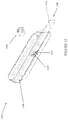
Figure 2 is a top rear perspective view of a lock arrangement offigure 1 ; -
Figure 3 is a top front perspective view of a lock arrangement offigure 1 ; -
Figure 4 is a front view of a lock arrangement offigure 1 ; -
Figure 5 is a top view of the lock arrangement without a skirt;Figure 6 is a top rear perspective view of a lock arrangement offigure 5 ; -
Figure 6 is a top rear perspective view of a lock arrangement offigure 5 ; -
Figure 7 is a front view of a lock arrangement offigure 5 ; -
Figure 8 is a top front perspective view of a lock arrangement offigure 5 ; -
Figure 9 is a top front perspective view of a shaped protrusion; -
Figure 10 is a top rear perspective view of a shaped protrusion offigure 9 ; -
Figure 11 is a top front perspective assembly view of a lock arrangement with the latch member in an extended position; -
Figure 12 is a top rear perspective assembly view of the lock arrangement offigure 11 with the latch member in an extended position; -
Figure 13 is a top section view of the lock arrangement offigure 11 with the latch member in an extended position; -
Figure 14 is a top front perspective view of a lock arrangement with the locking arrangement received in the lock receiving formation; -
Figure 15 is a top rear perspective assembly view of the lock arrangement offigure 14 with the locking arrangement received in the lock receiving formation; and -
Figure 16 is a top section view of the lock arrangement offigure 14 with the locking arrangement received in the lock receiving formation. - With reference to the above drawings, in which similar features are generally indicated by similar numerals, a locking assembly is indicated by the
numeral 1000. - In one embodiment now described, there is provided a
locking assembly 1000 suitable for locking a roller door (not shown). The lockingassembly 1000 comprises alatch assembly 1100 and alock arrangement 1200. - The
latch assembly 1100 comprises alatch tongue 1112 and abase arrangement 1120 securable to a roller door by means of securing formations (not shown). Thelatch tongue 1112 is movable between an extended position and a retracted position to latch the roller door. Thelatch tongue 1112 defines atongue aperture 1114. - The
base arrangement 1120 comprises a base plate 1122, and the base plate 1122 defines alatch aperture 1124. - The
latch tongue 1112 is elongate and planar. Thelatch tongue 1112 is movable between an extended position and a retracted position. - The
latch assembly 1100 is configurable to at least partly define alock receiving formation 1140. Thelock receiving formation 1140 is in the form of a shapedprotrusion 1144 surrounding alatch aperture 1124 configured to receive thelock arrangement 1200. The profile shape of theprotrusion 1144 is substantially oval or elliptical to complement the profile shape of thelock arrangement 1200. In another embodiment the latch tongue could also be locked in its retracted position. Thelatch tongue 1112 is locked in its extended position by inserting thelock arrangement 1200 into the shapedprotrusion 1144, thelatch aperture 1124 and thetongue aperture 1114. Thetongue aperture 1114 must be aligned with thelatch aperture 1124 to allow the insertion of thelock arrangement 1200. Insertion of thelock arrangement 1200 into thetongue aperture 1114 andlatch aperture 1124 prevents movement of thelatch tongue 1112 relative to thebase arrangement 1120. - In an alternative embodiment the lock arrangement need not be inserted into a tongue aperture, but could merely protrude into the path of movement of the latch tongue when it is in its extended position to prevent movement of the latch tongue into its retracted position.
- In a further embodiment the lock arrangement need not directly engage with the latch tongue, but could instead move an indirect coupling (not shown) to restrict movement of the latch tongue from its extended position.
- The
latch assembly 1100 andlock arrangement 1200 are complementarily configured to engage with each other operationally. - The shaped
protrusion 1144 is integrally formed with thebase arrangement 1120 or alternately secured to the base arrangement. The shapedprotrusion 1144 extends from thebase arrangement 1120 to afree end 1146. At thefree end 1146, the shapedprotrusion 1144 defines a curved contoured profile. It will be appreciated that a wide variety of profiles are possible and may be suitable for providing the advantages discussed below. - The shaped
protrusion 1144 defines a pair of locking ridges 1148 on aninner surface 1150. These locking ridges 1148 are involved in the locking of thelock arrangement 1200. - The shaped
protrusion 1144, the tongue aperture 1114 (in its extended position) and thelatch aperture 1124 together define the insertion passage for thelock arrangement 1200. - The
lock arrangement 1200 comprises alock body 1210 within which is housed akey cylinder 1220. Thekey cylinder 1220 is engageable by a key (not shown) to move between a locked position and an unlocked position. Thelock body 1210 is elliptical or substantially oval in shape, to complement the shaped profile of the shapedprotrusion 1144. - The
lock arrangement 1200 further comprises at least one and preferably a pair of opposed lockingmembers 1240 that are movable between an extended and a retracted position. The lockingmembers 1240 are biased to extend transversely from the lock body in their extended position when thekey cylinder 1220 is in its locked position, and when thekey cylinder 1220 is moved to its unlocked position this causes movement of the lockingmember 1240 to their retracted position. - The
lock arrangement 1200 also comprises askirt 1230 that extends around an outer surface of thelock body 1210. Theskirt 1230 need not necessarily extend all the way around lock body but it is preferable as this will allow a friction fit onto thelock body 1210. Theskirt 1230 also extends towards the end with the lockingmember 1240 and thefree end 1234 of theskirt 1230 has a profile complementary to the profile of the shapedprotrusion 1144. Theskirt 1230 is a plastic accessory fitting onto thelock body 1210. In another embodiment theskirt 1230 is integrally formed or secured to thelock body 1210 in a wide variety of other ways. - The contoured profiles are configured so that the
lock arrangement 1200 can only be inserted into the shapedprotrusion 1144 to cause the contoured profiles to fit together when thelock arrangement 1200 is aligned in one of two planes. In this alignment, thelock arrangement 1200 can be inserted into the shapedprotrusion 1144 with theskirt 1230 and the shapedprotrusion 1144 moving to be in a complementary alignment. The correct orientation and alignment of thelock arrangement 1200 with the shapedprotrusion 1144 is achieved by the ovoid shape of thelock arrangement 1200 and the mating of the complementary profiles. - The locking
members 1240 can move to their extended position when theskirt 1230 and the shapedprotrusion 1144 are abutting. The lockingmembers 1240 are extended and engage with the locking ridges 1148 to prevent extraction of thelock arrangement 1200. During insertion of thelock arrangement 1200 into the shapedprotrusion 1144 andlatch aperture 1124, the lockingmembers 1240 will be pushed towards their retracted position by theinner surface 1150. As the lock arrangement is inserted to the required depth, and thelocking members 1240 move past the locking ridges 1148, they will be free to move to their extended position under their bias. This will create a clicking or snapping noise, providing an audible confirmation to the correct alignment and depth of insertion. - Further, the depth of insertion will be such that the
lock arrangement 1200 will extend into the path of movement of thelatch tongue 1112 from its extended position to its retracted position, and into thetongue aperture 1114, thereby preventing movement of thelatch tongue 1112 from its extended position. - The
skirt 1230 further comprises grippingformations 1238 for providing grip to a user when inserting thelock arrangement 1200 into the shapedprotrusion 1144. - The advantages of the present invention include the provision of a visual cue to the user as to the required alignment/orientation of the lock arrangement as it is inserted by a user into the latch aperture, as well as to the depth of insertion required to ensure secure engagement of the locking members. This will ensure correct locking of the latch tongue and reduce the chances of unintentionally leaving doors unlocked.
- The lock arrangement includes a cylinder type lock with a skirt that can be correctly positioned and orientated in a door latch by the use of complementary profiles thereby enabling insertion in only one position and provide ease of use and confirmation that the lock has been correctly inserted and locked.
- The use of the oval shaped lock of the preferred embodiment provides the advantage to the owner or operator of a lockable facility that only oval shaped cylinder locks can be used by the tenant in order to secure the tenanted space.
- The lock arrangement can be used by owners and operators of storage facilities to lock storage bays where there is a dispute with the tenant and the latch allows the insertion of the lock arrangement to prevent unauthorized access.
- The lock arrangement is not fully received within the latch in the embodiments shown, however it is envisaged that it may be in other embodiments.
- In other alternative embodiments (not shown), the latch engaging formation may not be hollow or present an aperture at all, the base plate may not have an aperture with the locking arrangement extending along a side of the base plate, and in fact the base arrangement may not be a base plate at all, and could be of a wide variety of configurations, such as an elongate round bar, or any other suitable configuration for the purpose. Further, the latch tongue may not have an aperture, and instead the locking arrangement may simply engage with an exterior surface of the latch tongue to restrict movement from its extended position.
- It will of course be realised that while the foregoing has been given by way of illustrative example of this invention, all such and other modifications and variations thereto as would be apparent to persons skilled in the art are deemed to fall within the scope of this invention as it is defined by the claims.
- Throughout the description and claims of this specification the word "comprise" and variations of that word such as "comprises" and "comprising", are not intended to exclude other additives, components, integers or steps.
Claims (8)
- A lock arrangement (1200)
for use in association with a latch assembly (1100), said lock arrangement (1200) comprising:a lock body (1210) having a first end with a key aperture for a key and spring biased locking members (1240) extendable from adjacent a second end, the lock body (1210) has a shape that provides orientation with respect to positioning in the latch (1100); anda skirt (1230) substantially surrounding the lock body (1210) adjacent the first end and towards the second end, wherein a free end of the skirt (1230) has a curved profile complementary in shape to a curved profile of an extended end of a receiving formation (1140) substantially surrounding a latch aperture (1124) of the latch assembly (1100). - The lock arrangement as claimed in claim 1, wherein a length of the skirt (1230) and a position of the skirt (1230) on the lock body (1210) are configured to provide insertion position and orientation of the lock body (1210) with respect to the latch aperture (1124) of the latch assembly (1100) so that the lock body (1210) can lock a latch tongue (1112) of the latch assembly (1100) in an extended position.
- The lock arrangement as claimed in claim 1 or 2, wherein the skirt (1230) comprises one or more gripping surfaces (1238) to facilitate handling and installation of the lock body (1210) with respect to the latch assembly (1100).
- The lock arrangement as claimed in any preceding claim, wherein the skirt (1145) is integral with or attachable to the lock body (1210).
- The lock arrangement as claimed in any preceding claim, wherein the skirt (1145) is configured to provide a visual and/or audible feedback confirmation to a user of a correct insertion position and/or orientation of the lock body (1210) with respect to the latch aperture (1124).
- The lock arrangement as claimed in any preceding claim, wherein the lock body (1210) is oval in cross-section.
- The lock arrangement as claimed in claim 3, wherein the one or more gripping surfaces (1238) comprise a grip surface on an upper surface and/or a lower surface of the lock arrangement.
- The lock arrangement as claimed in any preceding claim, wherein the locking members (1240) are configured to move to an extended position when the skirt (1145) and the receiving formation are complementary aligned, and engage with locking ridges (1148) on the receiving formation (1140) to prevent extraction of the lock body (1210).
Applications Claiming Priority (1)
| Application Number | Priority Date | Filing Date | Title |
|---|---|---|---|
| PCT/AU2014/000781 WO2016019409A1 (en) | 2014-08-04 | 2014-08-04 | Lock arrangement |
Publications (3)
| Publication Number | Publication Date |
|---|---|
| EP3177790A1 EP3177790A1 (en) | 2017-06-14 |
| EP3177790A4 EP3177790A4 (en) | 2018-01-17 |
| EP3177790B1 true EP3177790B1 (en) | 2019-09-11 |
Family
ID=55262907
Family Applications (1)
| Application Number | Title | Priority Date | Filing Date |
|---|---|---|---|
| EP14899482.5A Active EP3177790B1 (en) | 2014-08-04 | 2014-08-04 | Lock arrangement |
Country Status (6)
| Country | Link |
|---|---|
| US (1) | US10017959B2 (en) |
| EP (1) | EP3177790B1 (en) |
| AU (1) | AU2014403141A1 (en) |
| EA (1) | EA201790181A1 (en) |
| SG (1) | SG11201700813TA (en) |
| WO (1) | WO2016019409A1 (en) |
Families Citing this family (2)
| Publication number | Priority date | Publication date | Assignee | Title |
|---|---|---|---|---|
| FR3080638B1 (en) * | 2018-04-25 | 2022-05-13 | Inducteurs Montage Creation | LOCKING DEVICE FOR DOORS |
| US12559974B2 (en) * | 2022-01-24 | 2026-02-24 | Timothy J. Costello | Latch tampering indicator |
Family Cites Families (22)
| Publication number | Priority date | Publication date | Assignee | Title |
|---|---|---|---|---|
| US2059698A (en) * | 1929-11-09 | 1936-11-03 | Briggs & Stratton Corp | Lock |
| US3465557A (en) * | 1967-11-15 | 1969-09-09 | Illinois Tool Works | Freezer lock assembly |
| US4099397A (en) * | 1977-06-29 | 1978-07-11 | Keystone Consolidated Industries, Inc. | Snap-in cylinder for disc and pin tumbler cam locks |
| US4381656A (en) * | 1979-11-30 | 1983-05-03 | Toyo Kogyo Co., Ltd. | Automobile door assembly having a door locking device |
| US4910982A (en) * | 1988-10-14 | 1990-03-27 | Engineered Security Products Corporation | Self-assembling locking device |
| US5435159A (en) * | 1989-10-03 | 1995-07-25 | Ramsauer; Dieter | Lock housing with flange for fitting in an aperture in a thin wall like a sheet metal cupboard door or sheet metal casing cover |
| US5251467A (en) * | 1992-09-08 | 1993-10-12 | Loctec Corporation | Front-installed cam lock |
| US5479800A (en) * | 1992-10-19 | 1996-01-02 | Fort Lock Corporation | Plastic lock |
| US5297405A (en) * | 1993-01-25 | 1994-03-29 | General Motors Corporation | Door handle assembly with snap-in key cylinder |
| US5724840A (en) * | 1996-03-21 | 1998-03-10 | Kaba High Security Locks Corporation | Cam lock |
| US5884510A (en) * | 1997-05-15 | 1999-03-23 | The Eastern Company | Bolt lock |
| US6079241A (en) * | 1998-04-27 | 2000-06-27 | Slc Technologies, Inc. | Method and apparatus for lock mounting |
| JP4073553B2 (en) * | 1998-09-02 | 2008-04-09 | 本田技研工業株式会社 | Key cylinder mounting structure |
| US6295850B1 (en) * | 1999-04-09 | 2001-10-02 | Loctec Corporation | Key-operated cylinder lock with removable plate tumbler container |
| USD469680S1 (en) * | 2001-01-24 | 2003-02-04 | The Eastern Company | Housing portions of a cam lock |
| US6523379B2 (en) * | 2001-04-20 | 2003-02-25 | Ryadon, Inc. | Locking cylinder and housing |
| US6684670B1 (en) * | 2002-08-07 | 2004-02-03 | Inner-Tite Corp. | Lock assembly with self retained barrel lock |
| US7100408B2 (en) * | 2004-03-02 | 2006-09-05 | Newfrey, Llc | Front loading lock assembly |
| US8347676B2 (en) * | 2004-11-30 | 2013-01-08 | Valeo Sistemas Automotivos Ltda. | Constructive improvement to an anti-theft lock device applied to automobile trunks |
| US20080289379A1 (en) * | 2007-05-23 | 2008-11-27 | Chateau Products, Inc. | Self-locking cylinder lock |
| EP2572065A4 (en) * | 2010-05-21 | 2017-09-20 | Janus International Group LLC | Door latch assembly |
| US20120103034A1 (en) * | 2010-11-01 | 2012-05-03 | Shartel Mark W | Lock for locking a movable member to fixed member |
-
2014
- 2014-08-04 EP EP14899482.5A patent/EP3177790B1/en active Active
- 2014-08-04 EA EA201790181A patent/EA201790181A1/en unknown
- 2014-08-04 WO PCT/AU2014/000781 patent/WO2016019409A1/en not_active Ceased
- 2014-08-04 SG SG11201700813TA patent/SG11201700813TA/en unknown
- 2014-08-04 AU AU2014403141A patent/AU2014403141A1/en not_active Abandoned
-
2017
- 2017-02-02 US US15/423,224 patent/US10017959B2/en not_active Expired - Fee Related
Non-Patent Citations (1)
| Title |
|---|
| None * |
Also Published As
| Publication number | Publication date |
|---|---|
| EA201790181A1 (en) | 2017-07-31 |
| EP3177790A1 (en) | 2017-06-14 |
| AU2014403141A1 (en) | 2017-03-02 |
| US10017959B2 (en) | 2018-07-10 |
| US20170198495A1 (en) | 2017-07-13 |
| EP3177790A4 (en) | 2018-01-17 |
| SG11201700813TA (en) | 2017-02-27 |
| WO2016019409A1 (en) | 2016-02-11 |
Similar Documents
| Publication | Publication Date | Title |
|---|---|---|
| EP2942456B1 (en) | Anti-theft lockset | |
| US20250263951A1 (en) | Rekeyable lock cylinder with enhanced torque resistance | |
| US7946142B2 (en) | Padlock hasp assembly | |
| US20180363334A1 (en) | Attachment member and lock having the same | |
| US5009087A (en) | Lock device with retaining cable | |
| US20140223976A1 (en) | Re-keyable cylinder lock | |
| US9297185B2 (en) | Padlock | |
| US10240371B2 (en) | Rolling door lock | |
| US10017959B2 (en) | Lock arrangement | |
| CA2926244C (en) | Cylinder lock with internal slider and key therefore | |
| US9963910B2 (en) | Locking device | |
| US20170350166A1 (en) | Magnetic lock and utility carts including same | |
| CN105257116A (en) | Device for opening and closing an article, especially made of leather, and article comprising such a device | |
| US20070234764A1 (en) | Hasps, Shackles and Padlocks | |
| US10435919B2 (en) | Anti-vandalism padlock | |
| KR101452848B1 (en) | A Safety Apparatus of Door | |
| US20170081878A1 (en) | Handcuff Shield | |
| WO2008147882A1 (en) | Self-locking cylinder lock | |
| JP5039173B2 (en) | Locking device for sliding door type automatic door device | |
| EP3097243B1 (en) | Cylinder lock and key in combination with the cylinder lock | |
| EP2511454B1 (en) | Lock capable of storing a key | |
| US20170226771A1 (en) | Handle-equipped lock | |
| JP4003972B2 (en) | Pin tumbler type cylinder lock for replacing the latch device of the door opening / closing handle | |
| NZ563652A (en) | A padlock having a removable shackle when the retaining means is not accessible when the padlock is closed | |
| AU2006281999B2 (en) | A padlock having a removable shackle |
Legal Events
| Date | Code | Title | Description |
|---|---|---|---|
| STAA | Information on the status of an ep patent application or granted ep patent |
Free format text: STATUS: THE INTERNATIONAL PUBLICATION HAS BEEN MADE |
|
| PUAI | Public reference made under article 153(3) epc to a published international application that has entered the european phase |
Free format text: ORIGINAL CODE: 0009012 |
|
| STAA | Information on the status of an ep patent application or granted ep patent |
Free format text: STATUS: REQUEST FOR EXAMINATION WAS MADE |
|
| 17P | Request for examination filed |
Effective date: 20170306 |
|
| AK | Designated contracting states |
Kind code of ref document: A1 Designated state(s): AL AT BE BG CH CY CZ DE DK EE ES FI FR GB GR HR HU IE IS IT LI LT LU LV MC MK MT NL NO PL PT RO RS SE SI SK SM TR |
|
| AX | Request for extension of the european patent |
Extension state: BA ME |
|
| DAX | Request for extension of the european patent (deleted) | ||
| A4 | Supplementary search report drawn up and despatched |
Effective date: 20171219 |
|
| RIC1 | Information provided on ipc code assigned before grant |
Ipc: E05B 17/04 20060101ALI20171213BHEP Ipc: E05B 17/20 20060101ALI20171213BHEP Ipc: E05B 65/00 20060101ALN20171213BHEP Ipc: E05B 9/04 20060101ALI20171213BHEP Ipc: E05B 67/36 20060101AFI20171213BHEP Ipc: E05C 1/04 20060101ALN20171213BHEP Ipc: E05B 15/12 20060101ALN20171213BHEP |
|
| RIC1 | Information provided on ipc code assigned before grant |
Ipc: E05B 9/04 20060101ALI20180126BHEP Ipc: E05B 15/12 20060101ALN20180126BHEP Ipc: E05B 65/00 20060101ALN20180126BHEP Ipc: E05B 17/04 20060101ALI20180126BHEP Ipc: E05C 1/04 20060101ALN20180126BHEP Ipc: E05B 17/20 20060101ALI20180126BHEP Ipc: E05B 67/36 20060101AFI20180126BHEP |
|
| REG | Reference to a national code |
Ref country code: HK Ref legal event code: DE Ref document number: 1239770 Country of ref document: HK |
|
| GRAP | Despatch of communication of intention to grant a patent |
Free format text: ORIGINAL CODE: EPIDOSNIGR1 |
|
| STAA | Information on the status of an ep patent application or granted ep patent |
Free format text: STATUS: GRANT OF PATENT IS INTENDED |
|
| RIC1 | Information provided on ipc code assigned before grant |
Ipc: E05B 67/36 20060101AFI20190308BHEP Ipc: E05B 65/00 20060101ALN20190308BHEP Ipc: E05B 15/12 20060101ALN20190308BHEP Ipc: E05B 9/04 20060101ALI20190308BHEP Ipc: E05B 17/04 20060101ALI20190308BHEP Ipc: E05C 1/04 20060101ALN20190308BHEP Ipc: E05B 17/20 20060101ALI20190308BHEP |
|
| INTG | Intention to grant announced |
Effective date: 20190409 |
|
| RIC1 | Information provided on ipc code assigned before grant |
Ipc: E05B 67/36 20060101AFI20190329BHEP Ipc: E05B 17/04 20060101ALI20190329BHEP Ipc: E05B 9/04 20060101ALI20190329BHEP Ipc: E05B 65/00 20060101ALN20190329BHEP Ipc: E05B 17/20 20060101ALI20190329BHEP Ipc: E05B 15/12 20060101ALN20190329BHEP Ipc: E05C 1/04 20060101ALN20190329BHEP |
|
| GRAS | Grant fee paid |
Free format text: ORIGINAL CODE: EPIDOSNIGR3 |
|
| GRAA | (expected) grant |
Free format text: ORIGINAL CODE: 0009210 |
|
| STAA | Information on the status of an ep patent application or granted ep patent |
Free format text: STATUS: THE PATENT HAS BEEN GRANTED |
|
| AK | Designated contracting states |
Kind code of ref document: B1 Designated state(s): AL AT BE BG CH CY CZ DE DK EE ES FI FR GB GR HR HU IE IS IT LI LT LU LV MC MK MT NL NO PL PT RO RS SE SI SK SM TR |
|
| REG | Reference to a national code |
Ref country code: GB Ref legal event code: FG4D |
|
| REG | Reference to a national code |
Ref country code: CH Ref legal event code: EP |
|
| REG | Reference to a national code |
Ref country code: AT Ref legal event code: REF Ref document number: 1178658 Country of ref document: AT Kind code of ref document: T Effective date: 20190915 |
|
| REG | Reference to a national code |
Ref country code: DE Ref legal event code: R096 Ref document number: 602014053687 Country of ref document: DE Ref country code: IE Ref legal event code: FG4D |
|
| REG | Reference to a national code |
Ref country code: NL Ref legal event code: MP Effective date: 20190911 |
|
| REG | Reference to a national code |
Ref country code: LT Ref legal event code: MG4D |
|
| PG25 | Lapsed in a contracting state [announced via postgrant information from national office to epo] |
Ref country code: NO Free format text: LAPSE BECAUSE OF FAILURE TO SUBMIT A TRANSLATION OF THE DESCRIPTION OR TO PAY THE FEE WITHIN THE PRESCRIBED TIME-LIMIT Effective date: 20191211 Ref country code: BG Free format text: LAPSE BECAUSE OF FAILURE TO SUBMIT A TRANSLATION OF THE DESCRIPTION OR TO PAY THE FEE WITHIN THE PRESCRIBED TIME-LIMIT Effective date: 20191211 Ref country code: LT Free format text: LAPSE BECAUSE OF FAILURE TO SUBMIT A TRANSLATION OF THE DESCRIPTION OR TO PAY THE FEE WITHIN THE PRESCRIBED TIME-LIMIT Effective date: 20190911 Ref country code: HR Free format text: LAPSE BECAUSE OF FAILURE TO SUBMIT A TRANSLATION OF THE DESCRIPTION OR TO PAY THE FEE WITHIN THE PRESCRIBED TIME-LIMIT Effective date: 20190911 Ref country code: SE Free format text: LAPSE BECAUSE OF FAILURE TO SUBMIT A TRANSLATION OF THE DESCRIPTION OR TO PAY THE FEE WITHIN THE PRESCRIBED TIME-LIMIT Effective date: 20190911 Ref country code: FI Free format text: LAPSE BECAUSE OF FAILURE TO SUBMIT A TRANSLATION OF THE DESCRIPTION OR TO PAY THE FEE WITHIN THE PRESCRIBED TIME-LIMIT Effective date: 20190911 |
|
| PG25 | Lapsed in a contracting state [announced via postgrant information from national office to epo] |
Ref country code: AL Free format text: LAPSE BECAUSE OF FAILURE TO SUBMIT A TRANSLATION OF THE DESCRIPTION OR TO PAY THE FEE WITHIN THE PRESCRIBED TIME-LIMIT Effective date: 20190911 Ref country code: ES Free format text: LAPSE BECAUSE OF FAILURE TO SUBMIT A TRANSLATION OF THE DESCRIPTION OR TO PAY THE FEE WITHIN THE PRESCRIBED TIME-LIMIT Effective date: 20190911 Ref country code: GR Free format text: LAPSE BECAUSE OF FAILURE TO SUBMIT A TRANSLATION OF THE DESCRIPTION OR TO PAY THE FEE WITHIN THE PRESCRIBED TIME-LIMIT Effective date: 20191212 Ref country code: RS Free format text: LAPSE BECAUSE OF FAILURE TO SUBMIT A TRANSLATION OF THE DESCRIPTION OR TO PAY THE FEE WITHIN THE PRESCRIBED TIME-LIMIT Effective date: 20190911 Ref country code: LV Free format text: LAPSE BECAUSE OF FAILURE TO SUBMIT A TRANSLATION OF THE DESCRIPTION OR TO PAY THE FEE WITHIN THE PRESCRIBED TIME-LIMIT Effective date: 20190911 |
|
| REG | Reference to a national code |
Ref country code: AT Ref legal event code: MK05 Ref document number: 1178658 Country of ref document: AT Kind code of ref document: T Effective date: 20190911 |
|
| PG25 | Lapsed in a contracting state [announced via postgrant information from national office to epo] |
Ref country code: RO Free format text: LAPSE BECAUSE OF FAILURE TO SUBMIT A TRANSLATION OF THE DESCRIPTION OR TO PAY THE FEE WITHIN THE PRESCRIBED TIME-LIMIT Effective date: 20190911 Ref country code: IT Free format text: LAPSE BECAUSE OF FAILURE TO SUBMIT A TRANSLATION OF THE DESCRIPTION OR TO PAY THE FEE WITHIN THE PRESCRIBED TIME-LIMIT Effective date: 20190911 Ref country code: PL Free format text: LAPSE BECAUSE OF FAILURE TO SUBMIT A TRANSLATION OF THE DESCRIPTION OR TO PAY THE FEE WITHIN THE PRESCRIBED TIME-LIMIT Effective date: 20190911 Ref country code: NL Free format text: LAPSE BECAUSE OF FAILURE TO SUBMIT A TRANSLATION OF THE DESCRIPTION OR TO PAY THE FEE WITHIN THE PRESCRIBED TIME-LIMIT Effective date: 20190911 Ref country code: AT Free format text: LAPSE BECAUSE OF FAILURE TO SUBMIT A TRANSLATION OF THE DESCRIPTION OR TO PAY THE FEE WITHIN THE PRESCRIBED TIME-LIMIT Effective date: 20190911 Ref country code: EE Free format text: LAPSE BECAUSE OF FAILURE TO SUBMIT A TRANSLATION OF THE DESCRIPTION OR TO PAY THE FEE WITHIN THE PRESCRIBED TIME-LIMIT Effective date: 20190911 Ref country code: PT Free format text: LAPSE BECAUSE OF FAILURE TO SUBMIT A TRANSLATION OF THE DESCRIPTION OR TO PAY THE FEE WITHIN THE PRESCRIBED TIME-LIMIT Effective date: 20200113 |
|
| PG25 | Lapsed in a contracting state [announced via postgrant information from national office to epo] |
Ref country code: IS Free format text: LAPSE BECAUSE OF FAILURE TO SUBMIT A TRANSLATION OF THE DESCRIPTION OR TO PAY THE FEE WITHIN THE PRESCRIBED TIME-LIMIT Effective date: 20200224 Ref country code: CZ Free format text: LAPSE BECAUSE OF FAILURE TO SUBMIT A TRANSLATION OF THE DESCRIPTION OR TO PAY THE FEE WITHIN THE PRESCRIBED TIME-LIMIT Effective date: 20190911 Ref country code: SK Free format text: LAPSE BECAUSE OF FAILURE TO SUBMIT A TRANSLATION OF THE DESCRIPTION OR TO PAY THE FEE WITHIN THE PRESCRIBED TIME-LIMIT Effective date: 20190911 Ref country code: SM Free format text: LAPSE BECAUSE OF FAILURE TO SUBMIT A TRANSLATION OF THE DESCRIPTION OR TO PAY THE FEE WITHIN THE PRESCRIBED TIME-LIMIT Effective date: 20190911 |
|
| REG | Reference to a national code |
Ref country code: DE Ref legal event code: R097 Ref document number: 602014053687 Country of ref document: DE |
|
| PLBE | No opposition filed within time limit |
Free format text: ORIGINAL CODE: 0009261 |
|
| STAA | Information on the status of an ep patent application or granted ep patent |
Free format text: STATUS: NO OPPOSITION FILED WITHIN TIME LIMIT |
|
| PG2D | Information on lapse in contracting state deleted |
Ref country code: IS |
|
| PG25 | Lapsed in a contracting state [announced via postgrant information from national office to epo] |
Ref country code: DK Free format text: LAPSE BECAUSE OF FAILURE TO SUBMIT A TRANSLATION OF THE DESCRIPTION OR TO PAY THE FEE WITHIN THE PRESCRIBED TIME-LIMIT Effective date: 20190911 Ref country code: IS Free format text: LAPSE BECAUSE OF FAILURE TO SUBMIT A TRANSLATION OF THE DESCRIPTION OR TO PAY THE FEE WITHIN THE PRESCRIBED TIME-LIMIT Effective date: 20200112 |
|
| 26N | No opposition filed |
Effective date: 20200615 |
|
| PG25 | Lapsed in a contracting state [announced via postgrant information from national office to epo] |
Ref country code: SI Free format text: LAPSE BECAUSE OF FAILURE TO SUBMIT A TRANSLATION OF THE DESCRIPTION OR TO PAY THE FEE WITHIN THE PRESCRIBED TIME-LIMIT Effective date: 20190911 |
|
| REG | Reference to a national code |
Ref country code: DE Ref legal event code: R119 Ref document number: 602014053687 Country of ref document: DE |
|
| PG25 | Lapsed in a contracting state [announced via postgrant information from national office to epo] |
Ref country code: MC Free format text: LAPSE BECAUSE OF FAILURE TO SUBMIT A TRANSLATION OF THE DESCRIPTION OR TO PAY THE FEE WITHIN THE PRESCRIBED TIME-LIMIT Effective date: 20190911 |
|
| REG | Reference to a national code |
Ref country code: CH Ref legal event code: PL |
|
| GBPC | Gb: european patent ceased through non-payment of renewal fee |
Effective date: 20200804 |
|
| PG25 | Lapsed in a contracting state [announced via postgrant information from national office to epo] |
Ref country code: CH Free format text: LAPSE BECAUSE OF NON-PAYMENT OF DUE FEES Effective date: 20200831 Ref country code: LI Free format text: LAPSE BECAUSE OF NON-PAYMENT OF DUE FEES Effective date: 20200831 Ref country code: LU Free format text: LAPSE BECAUSE OF NON-PAYMENT OF DUE FEES Effective date: 20200804 |
|
| REG | Reference to a national code |
Ref country code: BE Ref legal event code: MM Effective date: 20200831 |
|
| PG25 | Lapsed in a contracting state [announced via postgrant information from national office to epo] |
Ref country code: FR Free format text: LAPSE BECAUSE OF NON-PAYMENT OF DUE FEES Effective date: 20200831 Ref country code: DE Free format text: LAPSE BECAUSE OF NON-PAYMENT OF DUE FEES Effective date: 20210302 |
|
| PG25 | Lapsed in a contracting state [announced via postgrant information from national office to epo] |
Ref country code: BE Free format text: LAPSE BECAUSE OF NON-PAYMENT OF DUE FEES Effective date: 20200831 Ref country code: IE Free format text: LAPSE BECAUSE OF NON-PAYMENT OF DUE FEES Effective date: 20200804 Ref country code: GB Free format text: LAPSE BECAUSE OF NON-PAYMENT OF DUE FEES Effective date: 20200804 |
|
| PG25 | Lapsed in a contracting state [announced via postgrant information from national office to epo] |
Ref country code: TR Free format text: LAPSE BECAUSE OF FAILURE TO SUBMIT A TRANSLATION OF THE DESCRIPTION OR TO PAY THE FEE WITHIN THE PRESCRIBED TIME-LIMIT Effective date: 20190911 Ref country code: MT Free format text: LAPSE BECAUSE OF FAILURE TO SUBMIT A TRANSLATION OF THE DESCRIPTION OR TO PAY THE FEE WITHIN THE PRESCRIBED TIME-LIMIT Effective date: 20190911 Ref country code: CY Free format text: LAPSE BECAUSE OF FAILURE TO SUBMIT A TRANSLATION OF THE DESCRIPTION OR TO PAY THE FEE WITHIN THE PRESCRIBED TIME-LIMIT Effective date: 20190911 |
|
| PG25 | Lapsed in a contracting state [announced via postgrant information from national office to epo] |
Ref country code: MK Free format text: LAPSE BECAUSE OF FAILURE TO SUBMIT A TRANSLATION OF THE DESCRIPTION OR TO PAY THE FEE WITHIN THE PRESCRIBED TIME-LIMIT Effective date: 20190911 |
|
| REG | Reference to a national code |
Ref country code: HK Ref legal event code: WD Ref document number: 1239770 Country of ref document: HK |