EP3177486B1 - Mobile device holder for use in a vehicle - Google Patents
Mobile device holder for use in a vehicle Download PDFInfo
- Publication number
- EP3177486B1 EP3177486B1 EP15750226.1A EP15750226A EP3177486B1 EP 3177486 B1 EP3177486 B1 EP 3177486B1 EP 15750226 A EP15750226 A EP 15750226A EP 3177486 B1 EP3177486 B1 EP 3177486B1
- Authority
- EP
- European Patent Office
- Prior art keywords
- cover
- mobile device
- bin
- console
- cable
- Prior art date
- Legal status (The legal status is an assumption and is not a legal conclusion. Google has not performed a legal analysis and makes no representation as to the accuracy of the status listed.)
- Not-in-force
Links
- 229920001971 elastomer Polymers 0.000 claims description 4
- 239000000806 elastomer Substances 0.000 claims description 3
- 230000000712 assembly Effects 0.000 description 4
- 238000000429 assembly Methods 0.000 description 4
- 238000004140 cleaning Methods 0.000 description 4
- 238000003780 insertion Methods 0.000 description 3
- 230000037431 insertion Effects 0.000 description 3
- 239000012530 fluid Substances 0.000 description 2
- 230000002093 peripheral effect Effects 0.000 description 2
- 239000000758 substrate Substances 0.000 description 2
- 239000011248 coating agent Substances 0.000 description 1
- 238000000576 coating method Methods 0.000 description 1
- 238000010276 construction Methods 0.000 description 1
- 230000000994 depressogenic effect Effects 0.000 description 1
- 230000002708 enhancing effect Effects 0.000 description 1
- 239000002783 friction material Substances 0.000 description 1
- 238000009963 fulling Methods 0.000 description 1
- 239000010985 leather Substances 0.000 description 1
- 239000000463 material Substances 0.000 description 1
- 239000002184 metal Substances 0.000 description 1
- 239000004033 plastic Substances 0.000 description 1
- 230000000717 retained effect Effects 0.000 description 1
- 238000006748 scratching Methods 0.000 description 1
- 230000002393 scratching effect Effects 0.000 description 1
Images





Classifications
-
- B—PERFORMING OPERATIONS; TRANSPORTING
- B60—VEHICLES IN GENERAL
- B60R—VEHICLES, VEHICLE FITTINGS, OR VEHICLE PARTS, NOT OTHERWISE PROVIDED FOR
- B60R11/00—Arrangements for holding or mounting articles, not otherwise provided for
- B60R11/02—Arrangements for holding or mounting articles, not otherwise provided for for radio sets, television sets, telephones, or the like; Arrangement of controls thereof
- B60R11/0241—Arrangements for holding or mounting articles, not otherwise provided for for radio sets, television sets, telephones, or the like; Arrangement of controls thereof for telephones
-
- H—ELECTRICITY
- H04—ELECTRIC COMMUNICATION TECHNIQUE
- H04B—TRANSMISSION
- H04B1/00—Details of transmission systems, not covered by a single one of groups H04B3/00 - H04B13/00; Details of transmission systems not characterised by the medium used for transmission
- H04B1/38—Transceivers, i.e. devices in which transmitter and receiver form a structural unit and in which at least one part is used for functions of transmitting and receiving
- H04B1/3827—Portable transceivers
- H04B1/3877—Arrangements for enabling portable transceivers to be used in a fixed position, e.g. cradles or boosters
-
- B—PERFORMING OPERATIONS; TRANSPORTING
- B60—VEHICLES IN GENERAL
- B60R—VEHICLES, VEHICLE FITTINGS, OR VEHICLE PARTS, NOT OTHERWISE PROVIDED FOR
- B60R11/00—Arrangements for holding or mounting articles, not otherwise provided for
- B60R2011/0001—Arrangements for holding or mounting articles, not otherwise provided for characterised by position
- B60R2011/0003—Arrangements for holding or mounting articles, not otherwise provided for characterised by position inside the vehicle
- B60R2011/0007—Mid-console
-
- B—PERFORMING OPERATIONS; TRANSPORTING
- B60—VEHICLES IN GENERAL
- B60R—VEHICLES, VEHICLE FITTINGS, OR VEHICLE PARTS, NOT OTHERWISE PROVIDED FOR
- B60R11/00—Arrangements for holding or mounting articles, not otherwise provided for
- B60R2011/0042—Arrangements for holding or mounting articles, not otherwise provided for characterised by mounting means
- B60R2011/0049—Arrangements for holding or mounting articles, not otherwise provided for characterised by mounting means for non integrated articles
- B60R2011/0064—Connection with the article
- B60R2011/0075—Connection with the article using a containment or docking space
-
- B—PERFORMING OPERATIONS; TRANSPORTING
- B60—VEHICLES IN GENERAL
- B60R—VEHICLES, VEHICLE FITTINGS, OR VEHICLE PARTS, NOT OTHERWISE PROVIDED FOR
- B60R11/00—Arrangements for holding or mounting articles, not otherwise provided for
- B60R2011/0094—Arrangements for holding or mounting articles, not otherwise provided for characterised by means for covering after user, e.g. boxes, shutters or the like
Definitions
- the present invention relates to vehicle console assemblies, and more particularly to vehicle console assemblies including a mobile device holder.
- Vehicle console assemblies including console assemblies located between the driver and front passenger seats, in or near the vehicle dashboard or instrument panel, between or adjacent rear passenger seats, and in other locations are typically designed with a storage compartment and often include one or more cup holders. While driving, it is common for a vehicle user to place various personal objects (e.g., mobile electronic devices, keys, wallets, etc.) in the storage compartment or any cup holders of the console assembly. These solutions are not desirable for many vehicle occupants.
- various personal objects e.g., mobile electronic devices, keys, wallets, etc.
- the document US 2013/258604 A1 is representing the closest prior art, and discloses a console for a vehicle interior configured to position at least one mobile device connectable by a cable comprising: - a base providing a compartment; - a cover for the compartment movable to an open position; - a bin comprising an opening configured to provide storage for at least a portion of the cable; and - a cover for the bin; wherein the cover is configured to support at least one mobile device; and wherein the cover for the bin is configured to facilitate access for the cable in the bin.
- the cradle is provided on an underside of the cover.
- a console for a vehicle interior configured to position at least one mobile device connectable by a cable for use in the vehicle interior includes a base providing a compartment, a cover for the compartment movable to an open position providing a cradle for the mobile device, and a bin configured to provide storage for the cable and a cover for the bin.
- FIGS. 1 and 2 illustrate a vehicle 5 and a vehicle console assembly 10 located on the floor of the vehicle 5 between driver and passenger-side seats.
- the console assembly 10 includes a mobile device holder 14 ( FIG. 4A ) for a vehicle occupant to place or display various personal objects, such as a mobile device 18 (e.g., a mobile phone, a tablet computer, etc.) in a desired position and orientation (e.g., portrait or landscape).
- a mobile device 18 e.g., a mobile phone, a tablet computer, etc.
- the mobile device holder 14 may be located elsewhere within the interior of the vehicle 5.
- the mobile device holder 14 may be incorporated in a dashboard of the vehicle 5, as shown at 14a in FIG. 3 .
- the mobile device holder 14 may be incorporated in a rear console assembly (not shown) between driver and passenger-side rear seats, in an overhead console assembly attached to the roof of the vehicle 5, in an armrest of the vehicle 5, or in one or more door panels of the vehicle 5.
- the mobile device holder 14 includes a base 22 defining an compartment 26 and an opening 30 for accessing the compartment 26, and a support member or cover 34 coupled to the base 22 for selectively closing the opening 30 and supporting the entire weight of the mobile device 18.
- the base 22 is a separate component from the surrounding structure of the console assembly 10 and is attached to the surrounding structure of the console assembly 10 during assembly by multiple fasteners (not shown).
- Such fasteners may be configured as conventional threaded fasteners (e.g., screws or bolts), tool-less quick-connect elements (e.g., resilient locking elements), and the like.
- the base 22 may be integrally formed with the surrounding structure of the console assembly 10 as a single piece.
- the cover 34 is pivotably coupled to the base 22 about a pivot axis 38 ( FIG. 4C ) that is generally transverse to a longitudinal axis of the vehicle 5 (not shown).
- the vehicle console assembly 10 and/or the mobile device holder 14 may be reoriented within the interior of the vehicle 5 such that the pivot axis 38 of the cover 34 is oriented coaxial or parallel with the longitudinal axis of the vehicle 5.
- the mobile device holder 14 may be skewed toward the driver or passenger-side of the vehicle interior, thereby orienting the pivot axis 38 of the cover 34 in an oblique manner to the longitudinal axis of the vehicle 5, to facilitate viewing the mobile device 18 directly or head-on by either the driver or passenger in the front passenger-side seat.
- the cover 34 may be coupled to the base 22 in another manner providing a degree of freedom other than (or in addition to) pivoting.
- the cover 34 may be slidable relative to the base 22 rather than or in addition to being pivotable relative to the base 22.
- the cover 34 of the illustrated embodiment is pivotable between an open position ( FIGS. 4a and 4b ), in which the compartment 26 of the base 22 is accessible and an interior surface 46 of the cover 34 is oriented at an included angle A ( FIG. 11C ) with respect to a horizontal plane 50 passing through the console assembly 10 to provide an optimum viewing angle of the mobile device 18 for the occupants of the vehicle 5, to a closed position ( FIGS. 4d and 11a ), in which the opening 30 is closed and an exterior surface 54 of the cover 34 is generally flush with a surrounding top surface of the console assembly 10.
- the horizontal plane 50 ( FIG. 11C ) extends through the vehicle 5 and is generally parallel with the ground upon which the vehicle 5 sits. As shown in FIG.
- the included angle A is an oblique angle of about 60 degrees, thereby orienting the mobile device 18 supported upon the cover 34 in an oblique orientation relative to the horizontal plane 50.
- the included angle A may be less than about 60 degrees provided that the viewing angle of the mobile device 18 is acceptable to the occupants of the vehicle.
- the included angle A may be between about 60 degrees and about 90 degrees to support the mobile device 18 in a more upright orientation relative to the horizontal plane 50. At an included angle A of about 90 degrees, the mobile device 18 would be supported upon the cover 34 in an upright orientation relative to the horizontal plane 50.
- the cover 34 also includes multiple protrusions or cradles 58a-58c extending from the interior surface 46 upon which the mobile device 18 may be placed (see, for example, FIG. 4C ).
- the interior surface 46 is slip-resistant, which is provided by a soft cushion, coating, or overmold (interchangeably referred to as a "cushion 62"), for example, applied to a cover substrate 66 ( FIG. 5 ).
- the cushion 62 may be made from rubber, felt, leather, or another soft and/or high-friction material.
- the slip-resistant cushion 62 is applied to the entirety of the underside of the cover substrate 66, including the cradles 58a-58c, thereby further enhancing the grip upon the mobile device 18 that can be developed by the cover 34, and reducing the likelihood of damaging (e.g., by scratching, etc.) the mobile device 18 when it is supported by the cover 34.
- the cushion 62 may be only applied to the cradles 58a-58c or the interior surface 46.
- adjacent cradles 58a, 58b and 58b, 58c define respective openings 70a, 70b through which an attached electrical and/or data cable 74 of the mobile device 18 is insertable (see also FIG. 13 ).
- the mobile device 18 can be placed with its bottom end flat on adjacent cradles 58a, 58b or 58b, 58c in a portrait orientation without interference from the cable 74 or a device-end plug 78 of the cable 74.
- the cable 74 may be routed through the opening 70b.
- the cover 34 includes three cradles 58a-58c, a first opening 70a between a first and a second of the cradles 58a, 58b, and a second opening 70b between the second and a third of the cradles 58b, 58c ( FIG. 16 ).
- the cradle 58b is in the middle of the cover 34 and is at least twice as wide as the other cradles 58a, 58c, which are located on the extreme left and right sides of the cover 34 respectively.
- the cover 34 may include any of a number of different cradles 58a-58c and/or openings 70a, 70b in any of a number of different arrangements.
- the cover 34 may include only a single contiguous cradle spanning substantially the entire width of the cover 34, with or without notches, slots, or reliefs defined therein for placement of a cable 74 attached to the mobile device 18.
- the depth of the cradles 58a-58c is sufficiently large to accommodate mobile devices 18 of different thicknesses, and can even accommodate multiple mobile devices 18 in a stacked arrangement (i.e., with at least a second mobile device 18 placed atop and overlying a first mobile device 18 on the cover 34).
- the depth D of the cradles 58a-58c may be at least about 15 mm ( FIG. 7 ).
- the depth D of the cradles 58a-58c may be at least about 15 mm to about 25 mm, about 25 mm to about 35 mm, or about 35 mm to about 45 mm.
- the depth D of the cradles 58a-58c may be about 10 mm or less, and/or can be dimensioned to preclude mobile devices 18 from being stacked one on top of the other upon the cradles 58a-58c.
- the mobile device holder 14 also includes multiple electrical power and/or data ports 82 (e.g., a USB port) located within the compartment 26 of the base 22 and a cable organizer 86 (see also FIGS. 7-9 ) located beneath the cover 34 and between the ports 82.
- the cable organizer 86 includes a bin 90 in which one or more cables 74, or portions thereof, associated with one or more mobile devices 18 supported upon the cover 34 may be stored ( FIGS. 4b , 5 , and 7-9 ).
- the bin 90 includes a U-shaped opening 94 ( FIG.
- the bin 90 and/or the bin opening 94 may be configured to have any of a number of different shapes to accommodate the dimensions of the console assembly 10.
- the bin 90 may be shaped to span a substantial width of the base 22 so that multiple cables 74 from multiple mobile devices 18 positioned side-by-side on the cover 34 can be stored in the bin 90.
- the cover member 98 is configured as a flexible, stretchable and/or deformable elastomer sheet 102 clamped between the bin 90 and the base 22 ( FIG. 5 ).
- Three slits 106a-106c are formed in the sheet 102 in an "I" shape, thereby defining opposed flaps 110 that collectively cover the bin opening 94. More particularly, two of the slits 106a, 106b are laterally aligned with the respective openings 70a, 70b, while a third of the slits 106c extends transverse to and interconnects the slits 106a, 106b.
- circular holes 114 having a diameter at least as large as that of the cable 74 are formed at the ends of each of the slits 106a-106c through which the cable 74 may enter or exit the bin 90 without imparting a residual deflection upon either of the flaps 110.
- the opposite ends of the cable 74 may protrude through different holes 114 in the sheet 102 without deflecting the flaps 110.
- any other number of flaps 110 may be provided in a suitable arrangement (e.g., a single flap extending substantially the width of the bin 90).
- the opposed flaps 110 may be in contact with each other to completely close the bin opening 94, and the holes 114 may be omitted.
- the flaps 110 are sufficiently flexible to permit access to the different regions of the bin 90 for cleaning.
- the elastomer sheet 102 may be removable from the base 22 and/or bin 90 to allow unimpeded access to the different regions of the bin 90 for cleaning.
- the sheet 102 may be made of a rigid material (e.g., plastic, metal, etc.), and the flaps 110 may be movably coupled to the base 22 and/or the bin 90 in any of a number of different manners (e.g., using a pivoting arrangement, a sliding arrangement, etc.) to allow access into the bin 90 for stowing or removing the cable 74.
- a rigid sheet as the cover member 98 one or more of the flaps 110 may be removed to allow unimpeded access to the different regions of the bin 90 for cleaning.
- the cover member 98 may be configured as a rigid plate that covers the bin opening 94 and that is removable to allow unimpeded access to the different regions of the bin 90 for cleaning.
- a rigid plate may include one or more apertures through which opposite ends of the cable 74 may protrude for attachment to the port 82 and the mobile device 18, with the remainder of the cable 74 being contained within the bin 90 and shrouded by the rigid plate.
- the illustrated embodiment of the mobile device holder 14 includes a torsion spring assembly 146 coaxial with the pivot axis 38 that biases the cover 34 toward its open position.
- the torsion spring assembly 146 includes a first connector 150 received within an aperture 150 defined within an ear 154 of the cover 34, a second connector 162 received within an aperture 166 defined within a side wall of the base 22, and a torsion spring 118 having a first end affixed to the first connector 150 and a second end affixed to the second connector 162.
- the outer peripheral shape of the first connector 150 corresponds with the shape of the aperture 150; therefore, the first connector 150 is rotationally constrained to the cover 34.
- the outer peripheral shape of the second connector 162 corresponds with the shape of the aperture 166 in the base 22; therefore, the second connector 162 is rotationally constrained to the base 22.
- the first and second connectors 150, 162 are axially retained to each other, yet relative rotation between the first and second connectors 150, 162 is permitted. Accordingly, as the cover 34 is pivoted between the open and closed positions, the first connector 150 is rotated relative to the second connector 162, permitting the torsion spring 118 to unwind (when the cover 34 is opening) and wind (when the cover 34 is being closed).
- the cover 34 includes another ear 170 having a cylindrical protrusion 174 that is coaxial with the pivot axis 38 ( FIG. 11C ).
- the protrusion 174 is maintained in engagement with a guide wall 178, a portion of which is arcuate, formed on an opposite side wall of the base 22. In this manner, the protrusion 174 is slidable against the guide wall 178 as the cover 34 is pivoted between the open and closed positions while remaining coaxial with the pivot axis 38.
- any of a number of different features and/or components can be used to pivotably couple the cover 34 to the base 22 about the pivot axis 38.
- the mobile device holder 14 also includes a latch 122 (e.g., a push-push latch) for securing the cover 34 in its closed position.
- the latch 122 is received within a receptacle 182 offset from the pivot axis 38 and defined within a mounting flange 186 of the base 22 (see also FIGS. 10A and 10B ).
- the cover 34 includes a finger 190 (see also FIG. 5 ) offset from the pivot axis 38 that is engageable with the latch 122 when the cover 34 is secured in the closed position ( FIG. 10A ).
- the torsion spring 118 Upon releasing the latch 122 ( FIG. 10B ), the torsion spring 118 unwinds, thereby applying a torque to the cover 34 in the opening direction.
- the mobile device holder 14 also includes a damper 126 for controlling the rotational speed at which the cover 34 is opened.
- the damper 126 is configured as a rotary damper 126 including a gear 130 meshed with an arcuate toothed rack 134 formed on the cover 34 that is concentric with the pivot axis 38 (see also FIGS. 11a-11c and 15 ).
- the damper 126 includes a chamber in which a viscous fluid (e.g., oil) is contained and a rotor positioned within the fluid chamber to which the damper gear 130 is coupled for co-rotation. Accordingly, the damper 126 resists abrupt movement of the cover 34 as it is initially opened from the closed position. Thereafter, the damper 126 maintains the rotational speed of the cover 34 at a substantially constant rate as it is opened by the torsion spring 118.
- a viscous fluid e.g., oil
- a single mobile device 18 is shown placed on the adjacent cradles 58a, 58b in a portrait orientation with the cable 74 attached to the mobile device 18 extending through the opening 70a. Accordingly, a combination of a first and a second of the cradles 58a, 58b can be considered a first portion of the cover 34 upon which the mobile device 18 is supported.
- the mobile device 18 may be supported in the middle of the cover 34 by the cradle 58b or, if the width of the cradles 58a, 58c is about the same as or greater than one-half the width of the mobile device 18 (when viewed in a portrait orientation), the mobile device 18 may be supported on the extreme left or right sides of the cover 34 on the cradle 58a or the cradle 58c. Likewise, a single mobile device 18 may be placed upon any two adjacent cradles 58a, 58b or 58b, 58c in a landscape orientation, as shown in FIG.
- the length of the mobile device 18 may be supported in the middle of the cover 34 by only one of the cradles (e.g., the cradle 58b).
- a second mobile device 18a can be placed on the second and a third of the cradles 58b, 58c side by side with the first mobile device 18 in a portrait orientation, with the cable 74 attached to the mobile device 18a extending through the opening 70b.
- a combination of the second and third cradles 58b, 58c can be considered a second portion of the cover 34 upon which the second mobile device 18a is supported. Therefore, both a driver and a passenger of the vehicle 5 may place their respective mobile devices 18, 18a on the cover 34 when it is in the open position and electrically connect the devices 18, 18a to the respective ports 82 for charging and/or data transfer with a system of the vehicle 5.
- the first and second mobile devices 18, 18a can be placed side by side on the cradles 58a-58c, with the mobile device 18 in a landscape orientation and the mobile device 18a in a portrait orientation. Accordingly, a combination of a first and a second of the cradles 58a, 58b can be considered a first portion of the cover 34 upon which the mobile device 18 is supported, and a combination of the second and a third of the cradles 58b, 58c can be considered a second portion of the cover 34 upon which the second mobile device 18a is supported. Likewise, as shown in FIG.
- the first and second mobile devices 18, 18a can be placed side by side on the cradles 58a-58c in a landscape orientation. Accordingly, a combination of a first and a second of the cradles 58a, 58b can be considered a first portion of the cover 34 upon which the mobile device 18 is supported, and a combination of the second and a third of the cradles 58b, 58c can be considered a second portion of the cover 34 upon which the second mobile device 18a is supported.
- a user may open the cover 34 by pressing downward on a front portion of the cover 34 to release the latch 122 ( FIG. 10B ).
- the torsion spring 118 unwinds, thereby applying a torque to the cover 34 in an opening direction to pivot the cover 34 about the pivot axis 38.
- the toothed rack 134 also rotates about the pivot axis 38 ( FIGS. 11a-11c ), thereby rotating the damper gear 130.
- the damper 126 applies a reaction torque to the damper gear 130, and therefore the toothed rack 134, in an opposite direction.
- a user may place one or more mobile devices 18, 18a on the cradles 58a-58c of the cover 34 in a portrait or landscape orientation.
- a single mobile device 18 may be placed on the cover 34 in either a portrait orientation ( FIG. 16 ) or a landscape orientation ( FIG. 17 ), two mobile devices 18, 18a may be placed on the cover 34 side by side in portrait orientations ( FIG. 18 ), two mobile devices 18, 18a may be placed on the cover 34 side by side, one of which in a portrait orientation and the other in a landscape orientation ( FIG. 19 ), or two mobile devices 18, 18a may be placed on the cover 34 side by side in landscape orientations ( FIG. 20 ),
- the user may plug the cable 74 into the mobile device 18 and the port 82 to establish a data or power connection between the vehicle 5 and the mobile device 18 (see, for example, FIG. 4A ).
- Any excess length of the cable 74 may be inserted into the bin 90 of the cable organizer 86 by pushing or stuffing the cable 74 through the flaps 110 which, in turn, retain the inserted portion of the cable 74 within the bin 90.
- the overall aesthetic appearance of the console 10 is improved, and any interference posed by the cable 74 is reduced when a user interacts with the mobile device 18 and/or the port 82.
- the user can disconnect the cable 74 from the mobile device 18 and then push the mobile device-end plug 78 of the cable 74 into the bin 90 for storage ( FIGS. 4b and 7 ).
- the user may also disconnect a port-end plug 142 of the cable 74 from the port 82 and insert the port-end plug 142 into the bin 90 with the remainder of the cable 74 ( FIG. 9 ).
- the flaps 110 flex downward, thereby effectively enlarging the width of the slit 106b to accommodate the width of the port-end plug 142 ( FIG. 8 ).
- the user may pivot the cover 34 toward the closed position ( FIG. 4C ) to cover the cable organizer 86 and the ports 82.
- the latch 122 catches the cover 34 and maintains the cover 34 in the closed position against the bias of the torsion spring 118 ( FIG. 4D ).
- a mobile device holder 14 for use in a vehicle interior includes a base 22, a support member 34 coupled to the base 22 on which a mobile device 18 is supportable in either an oblique orientation or an upright orientation, and a cable organizer 86.
- the cable organizer 86 includes a bin 90 proximate the support member 34 into which a cable 74 for the mobile device 18 is receivable, and a cover member 98 at least partially covering the bin 90.
- the cover member 98 may be a flap 110 past which the cable 74 is movable for insertion into the bin 90.
- the flap 110 may be a first of a plurality of flaps 110 collectively covering the bin 90.
- the cover 98 may be a rigid plate removably coupled to the base 22.
- the rigid plate may include a hole through which an attached cable 74 of the mobile device 18 is receivable.
- the base 22 may define a compartment 26 and an opening 30 for accessing the compartment 26, and the support member 34 may be a cover 34 for selectively closing the opening 30.
- the cover 34 may include an interior surface 46 having a cushion 62 or a slip-resistant surface with which the mobile device 18 is in contact and supportable.
- the interior surface 46 of the cover 34 may define an included oblique angle A with respect to a horizontal plane 50 passing through the base 22 when the cover 34 is in an open position to facilitate viewing the mobile device 34.
- the cover 34 may be pivotably coupled to the base 22 between an open position in which the mobile device 18 is supportable on the interior surface 46, and a closed position in which the cover 34 closes the opening 30.
- the cover 34 includes a cradle 58a-c coupled to the interior surface 46 upon which the mobile device 18 is supportable.
- the cradle 58a-c may be a first of a plurality of cradles 58a-c coupled to the interior surface 46 of the cover 34, with adjacent cradles 58a, 58b or 58b, 58c defining an opening 70a, 70b through which an attached cable 74 of the mobile device 18 is insertable.
- a first mobile device 18 may be supportable by a combination of the first and a second of the plurality of cradles 58a, 58b, and a second mobile device 18a may be supportable by a combination of a third and a fourth of the plurality of cradles 58b, 58c.
- the interior surface 46 of the cover 34 may include a cushion 62 or a slip-resistant surface with which the mobile device 18 is in contact. Also in some embodiments, the interior surface 46 may be flat.
- the mobile device holder 14 may include a latch 122 for retaining the support member 34 in a closed position in which the opening 30 is closed. In other embodiments, the mobile device holder 14 may include a damper 126 for controlling the support member 34 when opening from a closed position in which the opening 30 is closed.
- the support member 34 may include a first portion upon which a first mobile device 18 is supportable in either an oblique orientation or an upright orientation, and a second portion upon which a second mobile device 18a is supportable in either an oblique orientation or an upright orientation, and in which the support member 34 is movable relative to the base 22 between an open position in which the first and second portions are accessible for supporting the respective first and second mobile devices 18, 18a thereon, and a closed position in which the first and second portions are inaccessible.
- the first portion of the support member 34 may be comprised of a first cradle 58a and a second cradle 58b defining therebetween a first opening 70a through which an attached cable 74 of the first mobile device 18 is insertable, and the second portion of the support member 34 may be comprised of the second cradle 58b and a third cradle 58c defining therebetween a second opening 70b through which an attached cable 74 of the second mobile device 18a is insertable.
- a mobile device holder 14 for use in a vehicular interior, and comprises a base 22 defining a compartment 26 and an opening 30 for accessing the compartment 26; and a cover 34 coupled to the base 22 for selectively closing the opening 30, wherein the cover 34 includes an interior surface 46 on which a mobile device 18 is supportable in either an oblique orientation or an upright orientation.
- the mobile device holder 14 may also comprise a cable organizer 86 incorporated in the base 22.
- the cable organizer 86 may include a bin 90 proximate the cover 34 into which a cable 74 for the mobile device 18 is receivable, and a cover 98 at least partially covering the bin 90.
- the cover 98 may be a deformable flap 110 past which the cable 74 is movable for insertion into the bin 90.
- the cover 34 is pivotably coupled to the base 22 between an open position in which the mobile device 18 is supportable on the interior surface 46, and a closed position in which the cover 34 closes the opening 30, and wherein the interior surface 46 includes a cushion 62 or a slip-resistant surface with which the mobile device 18 is in contact.
- a latch 122 is provided for retaining the cover 34 in a closed position in which the opening 30 is closed; and a damper 126 is provided for controlling movement of the cover 34 in response to being opened from the closed position.
- an electrical power port or a data port 82 is provided within the compartment 26 of the base 22.
- a mobile device holder 14 for use in a vehicular interior comprising a base 22, a cover 34 coupled to the base 22 and on which a mobile device 18 is supportable in either an oblique orientation or an upright orientation, and a cable organizer 86 incorporated in the base.
- the cable organizer 86 may include a bin 90 proximate the cover 34 into which a cable 74 for the mobile device 18 is receivable, and a cover 98 at least partially covering the bin 90.
- the cover 98 may be a flap 110 past which the cable 74 is movable for insertion into the bin 90.
- the base 22 defines a compartment 26 and an opening 30 for accessing the compartment 26, wherein the cover 34 selectively closes the opening 30.
- the cover 34 may include an interior surface 46 on which the mobile device 18 is supportable.
- an electrical power port or a data port 82 is provided within the compartment 26 of the base 22.
- a mobile device holder 14 for use in a vehicular interior comprises a base 22, and a cover 34 coupled to the base 22 and having a first portion 58a upon which a first mobile device 18a is supportable in either an oblique orientation or an upright orientation, and a second portion 58b upon which a second mobile device 18b is supportable in either an oblique orientation or an upright orientation, wherein the cover 34 is movable relative to the base 22 between an open position in which the first and second portions 58a, 58b are accessible for supporting the respective first and second mobile devices 18a, 18b thereon, and a closed position in which the first and second portions 58a, 58b are inaccessible.
- the first mobile device 18a includes a first thickness
- the second mobile device 18b includes a second thickness greater than the first thickness
- the first and second portions 58a, 58b of the cover 34 include a thickness at least as large as the second thickness of the second mobile device 18b.
- the base 22 may define a compartment 26 and an opening 30 for accessing the compartment 26, and the cover can selectively close the opening 30.
- the cover 34 may include an interior surface 46 on which at least one of the first mobile device 18a or the second mobile device 18b is supportable.
- an electrical power port or a data port 82 is provided within the compartment 26 of the base 22.
- a cable organizer 86 is incorporated in the base 22.
- the cable organizer 86 may include a bin 90 proximate the cover 34 into which a cable 74 of at least one of the first mobile device 18a or the second mobile device 18b is receivable, and a cover 98 at least partially covering the bin 90.
Landscapes
- Engineering & Computer Science (AREA)
- Mechanical Engineering (AREA)
- Computer Networks & Wireless Communication (AREA)
- Signal Processing (AREA)
- Fittings On The Vehicle Exterior For Carrying Loads, And Devices For Holding Or Mounting Articles (AREA)
- Vehicle Step Arrangements And Article Storage (AREA)
Description
- The present invention relates to vehicle console assemblies, and more particularly to vehicle console assemblies including a mobile device holder.
- Vehicle console assemblies, including console assemblies located between the driver and front passenger seats, in or near the vehicle dashboard or instrument panel, between or adjacent rear passenger seats, and in other locations are typically designed with a storage compartment and often include one or more cup holders. While driving, it is common for a vehicle user to place various personal objects (e.g., mobile electronic devices, keys, wallets, etc.) in the storage compartment or any cup holders of the console assembly. These solutions are not desirable for many vehicle occupants.
- The document
US 2013/258604 A1 is representing the closest prior art, and discloses a console for a vehicle interior configured to position at least one mobile device connectable by a cable comprising: - a base providing a compartment; - a cover for the compartment movable to an open position; - a bin comprising an opening configured to provide storage for at least a portion of the cable; and - a cover for the bin; wherein the cover is configured to support at least one mobile device; and wherein the cover for the bin is configured to facilitate access for the cable in the bin. - An apparatus configured to position at least one mobile device connectable by a cable for use in a vehicle interior includes a base providing a compartment and a cover for the compartment movable to an open position providing a cradle for at least one mobile device. The cradle is provided on an underside of the cover.
- A console for a vehicle interior configured to position at least one mobile device connectable by a cable for use in the vehicle interior includes a base providing a compartment, a cover for the compartment movable to an open position providing a cradle for the mobile device, and a bin configured to provide storage for the cable and a cover for the bin.
- Other features and aspects of the invention will become apparent by consideration of the following detailed description and accompanying drawings.
-
-
FIG. 1 is a rear perspective view of a vehicle. -
FIG. 2 is a rear perspective cutaway view of the vehicle ofFIG. 1 . -
FIG. 3 is a perspective view of an interior of the vehicle ofFIG. 1 , illustrating a vehicle console assembly. -
FIG. 4A is a top perspective view of a portion of the vehicle console assembly ofFIG. 2 , including a mobile device holder in accordance with an embodiment of the invention, illustrating a support member in an open position supporting a mobile device. -
FIG. 4B is a top perspective view of the mobile device holder ofFIG. 4A , illustrating the support member in the open position with the mobile device removed and an electrical cable of the mobile device partially stowed in a bin of the mobile device holder. -
FIG. 4C is a top perspective view of the mobile device holder ofFIG. 4A , illustrating the support member in a partially closed position. -
FIG. 4D is a top perspective view of the mobile device holder ofFIG. 4A , illustrating the support member in a closed position. -
FIG. 5 is an exploded perspective view of the mobile device holder ofFIG. 4A removed from the remainder of the vehicle console assembly. -
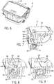
FIG. 6 is a top perspective view of the mobile device holder ofFIG. 4A removed from the remainder of the vehicle console assembly, illustrating the support member in the closed position. -
FIG. 7 is a cross-sectional perspective view of the mobile device holder ofFIG. 6 , illustrating the support member in the closed position. -
FIG. 8 is an enlarged view of the mobile device holder ofFIG. 7 , illustrating the electrical cable of the mobile device partially stowed in the bin of the mobile device holder. -
FIG. 9 is an enlarged view of the mobile device holder ofFIG. 7 , illustrating the electrical cable of the mobile device stowed in the bin of the mobile device holder. -
FIG. 10A is a side view of the mobile device holder ofFIG. 6 , illustrating the support member in the closed position. -
FIG. 10B is a side view of the mobile device holder ofFIG. 6 , illustrating the support member being depressed to release a latch for pivoting the support member to the open position. -
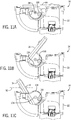
FIG. 11A is an opposite side view of the mobile device holder ofFIG. 6 , with portions shown in cutaway, illustrating the support member in the closed position. -
FIG. 11B is a side view of the mobile device holder ofFIG. 11A , illustrating the support member being pivoted toward the open position. -
FIG. 11C is a side view of the mobile device holder ofFIG. 11A , illustrating the support member in the closed position. -
FIG. 12 is a side perspective view of the mobile device holder ofFIG. 6 , illustrating the support member in the open position and a single mobile device supported thereon in a portrait orientation. -
FIG. 13 is a cross-sectional perspective view of the mobile device holder ofFIG. 12 with portions shown in cutaway. -
FIG. 14 is an opposite side perspective view of the mobile device holder ofFIG. 12 . -
FIG. 15 is a cross-sectional perspective view of the mobile device holder ofFIG. 14 . -
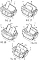
FIG. 16 is a top perspective view of the mobile device holder ofFIG. 6 , illustrating the support member in the open position and a single mobile device supported thereon in a portrait orientation. -
FIG. 17 is a top perspective view of the mobile device holder ofFIG. 6 , illustrating the support member in the open position and a single mobile device supported thereon in a landscape orientation. -
FIG. 18 is a top perspective view of the mobile device holder ofFIG. 6 , illustrating the support member in the open position and two mobile devices supported thereon side-by-side in portrait orientations. -
FIG. 19 is a top perspective view of the mobile device holder ofFIG. 6 , illustrating the support member in the open position and two mobile devices supported thereon side-by-side with a first of the mobile devices in a portrait orientation and a second of the mobile devices in a landscape orientation. -
FIG. 20 is a top perspective view of the mobile device holder ofFIG. 6 , illustrating the support member in the open position and two mobile devices supported thereon side-by-side in landscape orientations. - Before embodiments of the invention are explained in detail, it is to be understood that the invention is not limited in its application to the details of construction and the arrangement of components set forth in the following description or illustrated in the accompanying drawings. The invention is capable of other embodiments and of being practiced or of being carried out in various ways.
-
FIGS. 1 and 2 illustrate avehicle 5 and avehicle console assembly 10 located on the floor of thevehicle 5 between driver and passenger-side seats. Theconsole assembly 10 includes a mobile device holder 14 (FIG. 4A ) for a vehicle occupant to place or display various personal objects, such as a mobile device 18 (e.g., a mobile phone, a tablet computer, etc.) in a desired position and orientation (e.g., portrait or landscape). Alternatively, themobile device holder 14 may be located elsewhere within the interior of thevehicle 5. For example, themobile device holder 14 may be incorporated in a dashboard of thevehicle 5, as shown at 14a inFIG. 3 . As a further alternative, themobile device holder 14 may be incorporated in a rear console assembly (not shown) between driver and passenger-side rear seats, in an overhead console assembly attached to the roof of thevehicle 5, in an armrest of thevehicle 5, or in one or more door panels of thevehicle 5. - With reference to
FIG. 5 , themobile device holder 14 includes abase 22 defining ancompartment 26 and anopening 30 for accessing thecompartment 26, and a support member orcover 34 coupled to thebase 22 for selectively closing the opening 30 and supporting the entire weight of themobile device 18. In the illustrated embodiment of themobile device holder 14, thebase 22 is a separate component from the surrounding structure of theconsole assembly 10 and is attached to the surrounding structure of theconsole assembly 10 during assembly by multiple fasteners (not shown). Such fasteners may be configured as conventional threaded fasteners (e.g., screws or bolts), tool-less quick-connect elements (e.g., resilient locking elements), and the like. Alternatively, thebase 22 may be integrally formed with the surrounding structure of theconsole assembly 10 as a single piece. - In the illustrated embodiment of the
mobile device holder 14, thecover 34 is pivotably coupled to the base 22 about a pivot axis 38 (FIG. 4C ) that is generally transverse to a longitudinal axis of the vehicle 5 (not shown). Alternatively, thevehicle console assembly 10 and/or themobile device holder 14 may be reoriented within the interior of thevehicle 5 such that thepivot axis 38 of thecover 34 is oriented coaxial or parallel with the longitudinal axis of thevehicle 5. In yet another embodiment, themobile device holder 14 may be skewed toward the driver or passenger-side of the vehicle interior, thereby orienting thepivot axis 38 of thecover 34 in an oblique manner to the longitudinal axis of thevehicle 5, to facilitate viewing themobile device 18 directly or head-on by either the driver or passenger in the front passenger-side seat. In a further embodiment, thecover 34 may be coupled to the base 22 in another manner providing a degree of freedom other than (or in addition to) pivoting. For example, thecover 34 may be slidable relative to the base 22 rather than or in addition to being pivotable relative to thebase 22. - The
cover 34 of the illustrated embodiment is pivotable between an open position (FIGS. 4a and 4b ), in which thecompartment 26 of thebase 22 is accessible and aninterior surface 46 of thecover 34 is oriented at an included angle A (FIG. 11C ) with respect to ahorizontal plane 50 passing through theconsole assembly 10 to provide an optimum viewing angle of themobile device 18 for the occupants of thevehicle 5, to a closed position (FIGS. 4d and11a ), in which theopening 30 is closed and anexterior surface 54 of thecover 34 is generally flush with a surrounding top surface of theconsole assembly 10. The horizontal plane 50 (FIG. 11C ) extends through thevehicle 5 and is generally parallel with the ground upon which thevehicle 5 sits. As shown inFIG. 11C , in the illustrated embodiment of themobile device holder 14, the included angle A is an oblique angle of about 60 degrees, thereby orienting themobile device 18 supported upon thecover 34 in an oblique orientation relative to thehorizontal plane 50. Alternatively, when thecover 34 is in the open position, the included angle A may be less than about 60 degrees provided that the viewing angle of themobile device 18 is acceptable to the occupants of the vehicle. Likewise, when thecover 34 is in the open position, the included angle A may be between about 60 degrees and about 90 degrees to support themobile device 18 in a more upright orientation relative to thehorizontal plane 50. At an included angle A of about 90 degrees, themobile device 18 would be supported upon thecover 34 in an upright orientation relative to thehorizontal plane 50. - With reference to
FIG. 5 , thecover 34 also includes multiple protrusions or cradles 58a-58c extending from theinterior surface 46 upon which themobile device 18 may be placed (see, for example,FIG. 4C ). To enhance grip on themobile device 18, theinterior surface 46 is slip-resistant, which is provided by a soft cushion, coating, or overmold (interchangeably referred to as a "cushion 62"), for example, applied to a cover substrate 66 (FIG. 5 ). For example, thecushion 62 may be made from rubber, felt, leather, or another soft and/or high-friction material. In the illustrated embodiment of themobile device holder 14, the slip-resistant cushion 62 is applied to the entirety of the underside of thecover substrate 66, including thecradles 58a-58c, thereby further enhancing the grip upon themobile device 18 that can be developed by thecover 34, and reducing the likelihood of damaging (e.g., by scratching, etc.) themobile device 18 when it is supported by thecover 34. Alternatively, thecushion 62 may be only applied to thecradles 58a-58c or theinterior surface 46. - With continued reference to
FIG. 5 ,adjacent cradles respective openings data cable 74 of themobile device 18 is insertable (see alsoFIG. 13 ). In this manner, themobile device 18 can be placed with its bottom end flat onadjacent cradles cable 74 or a device-end plug 78 of thecable 74. Furthermore, when themobile device 14 is placed on its side flat onadjacent cradles FIG. 17 ), thecable 74 may be routed through theopening 70b. In the illustrated embodiment of themobile device holder 14, thecover 34 includes threecradles 58a-58c, afirst opening 70a between a first and a second of thecradles second opening 70b between the second and a third of thecradles FIG. 16 ). Thecradle 58b is in the middle of thecover 34 and is at least twice as wide as theother cradles cover 34 respectively. Alternatively, thecover 34 may include any of a number ofdifferent cradles 58a-58c and/oropenings cover 34 may include only a single contiguous cradle spanning substantially the entire width of thecover 34, with or without notches, slots, or reliefs defined therein for placement of acable 74 attached to themobile device 18. - In the illustrated embodiment of the
mobile device holder 14, the depth of thecradles 58a-58c is sufficiently large to accommodatemobile devices 18 of different thicknesses, and can even accommodate multiplemobile devices 18 in a stacked arrangement (i.e., with at least a secondmobile device 18 placed atop and overlying a firstmobile device 18 on the cover 34). For example, the depth D of thecradles 58a-58c may be at least about 15 mm (FIG. 7 ). In other embodiments of themobile device holder 14, and depending upon the relative size of thevehicle 5 in which theconsole 10 is incorporated, the depth D of thecradles 58a-58c may be at least about 15 mm to about 25 mm, about 25 mm to about 35 mm, or about 35 mm to about 45 mm. Alternatively, the depth D of thecradles 58a-58c may be about 10 mm or less, and/or can be dimensioned to precludemobile devices 18 from being stacked one on top of the other upon thecradles 58a-58c. - With reference to
FIG. 5 , themobile device holder 14 also includes multiple electrical power and/or data ports 82 (e.g., a USB port) located within thecompartment 26 of thebase 22 and a cable organizer 86 (see alsoFIGS. 7-9 ) located beneath thecover 34 and between theports 82. Thecable organizer 86 includes abin 90 in which one ormore cables 74, or portions thereof, associated with one or moremobile devices 18 supported upon thecover 34 may be stored (FIGS. 4b ,5 , and7-9 ). In the illustrated embodiment of thecable organizer 86, thebin 90 includes a U-shaped opening 94 (FIG. 5 ) overlaid with acover member 98 for substantially closing theopening 94 and obstructing the vehicle occupants' view into thebin 90. Alternatively, thebin 90 and/or thebin opening 94 may be configured to have any of a number of different shapes to accommodate the dimensions of theconsole assembly 10. Furthermore, thebin 90 may be shaped to span a substantial width of the base 22 so thatmultiple cables 74 from multiplemobile devices 18 positioned side-by-side on thecover 34 can be stored in thebin 90. - In the illustrated embodiment of the
cable organizer 86, thecover member 98 is configured as a flexible, stretchable and/ordeformable elastomer sheet 102 clamped between the bin 90 and the base 22 (FIG. 5 ). Threeslits 106a-106c are formed in thesheet 102 in an "I" shape, thereby definingopposed flaps 110 that collectively cover thebin opening 94. More particularly, two of theslits respective openings slits 106c extends transverse to and interconnects theslits slits 106a-c,circular holes 114 having a diameter at least as large as that of thecable 74 are formed at the ends of each of theslits 106a-106c through which thecable 74 may enter or exit thebin 90 without imparting a residual deflection upon either of theflaps 110. In other words, after the middle length of thecable 74 is stored in thebin 90, the opposite ends of thecable 74 may protrude throughdifferent holes 114 in thesheet 102 without deflecting theflaps 110. Although twoflaps 110 are shown in the illustrated embodiment, any other number offlaps 110 may be provided in a suitable arrangement (e.g., a single flap extending substantially the width of the bin 90). Alternatively, theopposed flaps 110 may be in contact with each other to completely close thebin opening 94, and theholes 114 may be omitted. Theflaps 110 are sufficiently flexible to permit access to the different regions of thebin 90 for cleaning. Alternatively, theelastomer sheet 102 may be removable from thebase 22 and/orbin 90 to allow unimpeded access to the different regions of thebin 90 for cleaning. - Alternatively, the
sheet 102 may be made of a rigid material (e.g., plastic, metal, etc.), and theflaps 110 may be movably coupled to thebase 22 and/or thebin 90 in any of a number of different manners (e.g., using a pivoting arrangement, a sliding arrangement, etc.) to allow access into thebin 90 for stowing or removing thecable 74. With such a rigid sheet as thecover member 98, one or more of theflaps 110 may be removed to allow unimpeded access to the different regions of thebin 90 for cleaning. As a further alternative, thecover member 98 may be configured as a rigid plate that covers thebin opening 94 and that is removable to allow unimpeded access to the different regions of thebin 90 for cleaning. Such a rigid plate may include one or more apertures through which opposite ends of thecable 74 may protrude for attachment to theport 82 and themobile device 18, with the remainder of thecable 74 being contained within thebin 90 and shrouded by the rigid plate. - With reference to
FIG. 5 , the illustrated embodiment of themobile device holder 14 includes atorsion spring assembly 146 coaxial with thepivot axis 38 that biases thecover 34 toward its open position. Thetorsion spring assembly 146 includes afirst connector 150 received within anaperture 150 defined within anear 154 of thecover 34, asecond connector 162 received within anaperture 166 defined within a side wall of thebase 22, and atorsion spring 118 having a first end affixed to thefirst connector 150 and a second end affixed to thesecond connector 162. The outer peripheral shape of thefirst connector 150 corresponds with the shape of theaperture 150; therefore, thefirst connector 150 is rotationally constrained to thecover 34. Likewise, the outer peripheral shape of thesecond connector 162 corresponds with the shape of theaperture 166 in thebase 22; therefore, thesecond connector 162 is rotationally constrained to thebase 22. The first andsecond connectors second connectors cover 34 is pivoted between the open and closed positions, thefirst connector 150 is rotated relative to thesecond connector 162, permitting thetorsion spring 118 to unwind (when thecover 34 is opening) and wind (when thecover 34 is being closed). - With continued reference to
FIG. 5 , on an opposite side, thecover 34 includes anotherear 170 having acylindrical protrusion 174 that is coaxial with the pivot axis 38 (FIG. 11C ). Theprotrusion 174 is maintained in engagement with aguide wall 178, a portion of which is arcuate, formed on an opposite side wall of thebase 22. In this manner, theprotrusion 174 is slidable against theguide wall 178 as thecover 34 is pivoted between the open and closed positions while remaining coaxial with thepivot axis 38. Alternatively, any of a number of different features and/or components can be used to pivotably couple thecover 34 to the base 22 about thepivot axis 38. - With reference to
FIG. 5 , themobile device holder 14 also includes a latch 122 (e.g., a push-push latch) for securing thecover 34 in its closed position. Thelatch 122 is received within areceptacle 182 offset from thepivot axis 38 and defined within a mountingflange 186 of the base 22 (see alsoFIGS. 10A and 10B ). Thecover 34 includes a finger 190 (see alsoFIG. 5 ) offset from thepivot axis 38 that is engageable with thelatch 122 when thecover 34 is secured in the closed position (FIG. 10A ). Upon releasing the latch 122 (FIG. 10B ), thetorsion spring 118 unwinds, thereby applying a torque to thecover 34 in the opening direction. - With reference to
FIGS. 5 and14 , themobile device holder 14 also includes adamper 126 for controlling the rotational speed at which thecover 34 is opened. In the illustrated embodiment of themobile device holder 14, thedamper 126 is configured as arotary damper 126 including agear 130 meshed with an arcuatetoothed rack 134 formed on thecover 34 that is concentric with the pivot axis 38 (see alsoFIGS. 11a-11c and15 ). Thedamper 126 includes a chamber in which a viscous fluid (e.g., oil) is contained and a rotor positioned within the fluid chamber to which thedamper gear 130 is coupled for co-rotation. Accordingly, thedamper 126 resists abrupt movement of thecover 34 as it is initially opened from the closed position. Thereafter, thedamper 126 maintains the rotational speed of thecover 34 at a substantially constant rate as it is opened by thetorsion spring 118. - With reference to
FIG. 16 , a singlemobile device 18 is shown placed on theadjacent cradles cable 74 attached to themobile device 18 extending through theopening 70a. Accordingly, a combination of a first and a second of thecradles cover 34 upon which themobile device 18 is supported. If thecable 74 is unattached, themobile device 18 may be supported in the middle of thecover 34 by thecradle 58b or, if the width of thecradles mobile device 18 may be supported on the extreme left or right sides of thecover 34 on thecradle 58a or thecradle 58c. Likewise, a singlemobile device 18 may be placed upon any twoadjacent cradles FIG. 17 , with thecable 74 passing through one of theopenings opening 70b as shown inFIG. 17 ) before passing through one of theholes 114 in thesheet 102. Provided that the length of themobile device 18 is sufficiently short (when viewed in the landscape orientation), it may be supported in the middle of thecover 34 by only one of the cradles (e.g., thecradle 58b). - As shown in
FIG. 18 , a secondmobile device 18a can be placed on the second and a third of thecradles mobile device 18 in a portrait orientation, with thecable 74 attached to themobile device 18a extending through theopening 70b. Accordingly, a combination of the second andthird cradles cover 34 upon which the secondmobile device 18a is supported. Therefore, both a driver and a passenger of thevehicle 5 may place their respectivemobile devices cover 34 when it is in the open position and electrically connect thedevices respective ports 82 for charging and/or data transfer with a system of thevehicle 5. - As shown in
FIG. 19 , the first and secondmobile devices cradles 58a-58c, with themobile device 18 in a landscape orientation and themobile device 18a in a portrait orientation. Accordingly, a combination of a first and a second of thecradles cover 34 upon which themobile device 18 is supported, and a combination of the second and a third of thecradles cover 34 upon which the secondmobile device 18a is supported. Likewise, as shown inFIG. 20 , the first and secondmobile devices cradles 58a-58c in a landscape orientation. Accordingly, a combination of a first and a second of thecradles cover 34 upon which themobile device 18 is supported, and a combination of the second and a third of thecradles cover 34 upon which the secondmobile device 18a is supported. - In operation, beginning with the
cover 34 in the closed position as shown in inFIG. 10A , a user may open thecover 34 by pressing downward on a front portion of thecover 34 to release the latch 122 (FIG. 10B ). After thelatch 122 is released, thetorsion spring 118 unwinds, thereby applying a torque to thecover 34 in an opening direction to pivot thecover 34 about thepivot axis 38. As thecover 34 opens, thetoothed rack 134 also rotates about the pivot axis 38 (FIGS. 11a-11c ), thereby rotating thedamper gear 130. Thedamper 126, in turn, applies a reaction torque to thedamper gear 130, and therefore thetoothed rack 134, in an opposite direction. As a result, pivoting of thecover 34 in the opening direction occurs at a substantially constant and relatively low rotational rate until thecover 34 assumes the open position (FIG. 11C ). Once thecover 34 is in the open position, a user may place one or moremobile devices cradles 58a-58c of thecover 34 in a portrait or landscape orientation. For example, a singlemobile device 18 may be placed on thecover 34 in either a portrait orientation (FIG. 16 ) or a landscape orientation (FIG. 17 ), twomobile devices cover 34 side by side in portrait orientations (FIG. 18 ), twomobile devices cover 34 side by side, one of which in a portrait orientation and the other in a landscape orientation (FIG. 19 ), or twomobile devices cover 34 side by side in landscape orientations (FIG. 20 ), - If desired, the user may plug the
cable 74 into themobile device 18 and theport 82 to establish a data or power connection between thevehicle 5 and the mobile device 18 (see, for example,FIG. 4A ). Any excess length of thecable 74 may be inserted into thebin 90 of thecable organizer 86 by pushing or stuffing thecable 74 through theflaps 110 which, in turn, retain the inserted portion of thecable 74 within thebin 90. By tucking the middle portion or excess length of thecable 74 into thecable organizer 86, the overall aesthetic appearance of theconsole 10 is improved, and any interference posed by thecable 74 is reduced when a user interacts with themobile device 18 and/or theport 82. - If the user decides to remove the
mobile device 18 from thedevice holder 14, the user can disconnect thecable 74 from themobile device 18 and then push the mobile device-end plug 78 of thecable 74 into thebin 90 for storage (FIGS. 4b and7 ). Optionally, the user may also disconnect a port-end plug 142 of thecable 74 from theport 82 and insert the port-end plug 142 into thebin 90 with the remainder of the cable 74 (FIG. 9 ). As the port-end plug 142 of thecable 74 is pushed between theflaps 110, theflaps 110 flex downward, thereby effectively enlarging the width of theslit 106b to accommodate the width of the port-end plug 142 (FIG. 8 ). Afterwards, the user may pivot thecover 34 toward the closed position (FIG. 4C ) to cover thecable organizer 86 and theports 82. Upon reaching the closed position, thelatch 122 catches thecover 34 and maintains thecover 34 in the closed position against the bias of the torsion spring 118 (FIG. 4D ). - According to an exemplary embodiment, a
mobile device holder 14 for use in a vehicle interior includes abase 22, asupport member 34 coupled to the base 22 on which amobile device 18 is supportable in either an oblique orientation or an upright orientation, and acable organizer 86. Thecable organizer 86 includes abin 90 proximate thesupport member 34 into which acable 74 for themobile device 18 is receivable, and acover member 98 at least partially covering thebin 90. - In some embodiments, the
cover member 98 may be aflap 110 past which thecable 74 is movable for insertion into thebin 90. Theflap 110 may be a first of a plurality offlaps 110 collectively covering thebin 90. In other embodiments, thecover 98 may be a rigid plate removably coupled to thebase 22. The rigid plate may include a hole through which an attachedcable 74 of themobile device 18 is receivable. - In some embodiments, the
base 22 may define acompartment 26 and anopening 30 for accessing thecompartment 26, and thesupport member 34 may be acover 34 for selectively closing theopening 30. Thecover 34 may include aninterior surface 46 having acushion 62 or a slip-resistant surface with which themobile device 18 is in contact and supportable. Theinterior surface 46 of thecover 34 may define an included oblique angle A with respect to ahorizontal plane 50 passing through the base 22 when thecover 34 is in an open position to facilitate viewing themobile device 34. In some embodiments, thecover 34 may be pivotably coupled to the base 22 between an open position in which themobile device 18 is supportable on theinterior surface 46, and a closed position in which thecover 34 closes theopening 30. - The
cover 34 includes acradle 58a-c coupled to theinterior surface 46 upon which themobile device 18 is supportable. Thecradle 58a-c may be a first of a plurality ofcradles 58a-c coupled to theinterior surface 46 of thecover 34, withadjacent cradles opening cable 74 of themobile device 18 is insertable. A firstmobile device 18 may be supportable by a combination of the first and a second of the plurality ofcradles mobile device 18a may be supportable by a combination of a third and a fourth of the plurality ofcradles interior surface 46 of thecover 34 may include acushion 62 or a slip-resistant surface with which themobile device 18 is in contact. Also in some embodiments, theinterior surface 46 may be flat. - In some embodiments, the
mobile device holder 14 may include alatch 122 for retaining thesupport member 34 in a closed position in which theopening 30 is closed. In other embodiments, themobile device holder 14 may include adamper 126 for controlling thesupport member 34 when opening from a closed position in which theopening 30 is closed. - In some embodiments, the
support member 34 may include a first portion upon which a firstmobile device 18 is supportable in either an oblique orientation or an upright orientation, and a second portion upon which a secondmobile device 18a is supportable in either an oblique orientation or an upright orientation, and in which thesupport member 34 is movable relative to the base 22 between an open position in which the first and second portions are accessible for supporting the respective first and secondmobile devices support member 34 may be comprised of afirst cradle 58a and asecond cradle 58b defining therebetween afirst opening 70a through which an attachedcable 74 of the firstmobile device 18 is insertable, and the second portion of thesupport member 34 may be comprised of thesecond cradle 58b and athird cradle 58c defining therebetween asecond opening 70b through which an attachedcable 74 of the secondmobile device 18a is insertable. - In some embodiments, a
mobile device holder 14 for use in a vehicular interior is provided, and comprises a base 22 defining acompartment 26 and anopening 30 for accessing thecompartment 26; and acover 34 coupled to thebase 22 for selectively closing theopening 30, wherein thecover 34 includes aninterior surface 46 on which amobile device 18 is supportable in either an oblique orientation or an upright orientation. Themobile device holder 14 may also comprise acable organizer 86 incorporated in thebase 22. Thecable organizer 86 may include abin 90 proximate thecover 34 into which acable 74 for themobile device 18 is receivable, and acover 98 at least partially covering thebin 90. Also, thecover 98 may be adeformable flap 110 past which thecable 74 is movable for insertion into thebin 90. In some embodiments, thecover 34 is pivotably coupled to the base 22 between an open position in which themobile device 18 is supportable on theinterior surface 46, and a closed position in which thecover 34 closes theopening 30, and wherein theinterior surface 46 includes acushion 62 or a slip-resistant surface with which themobile device 18 is in contact. Also, in some embodiments alatch 122 is provided for retaining thecover 34 in a closed position in which theopening 30 is closed; and adamper 126 is provided for controlling movement of thecover 34 in response to being opened from the closed position. In some embodiments, an electrical power port or adata port 82 is provided within thecompartment 26 of thebase 22. - Some embodiments provide a
mobile device holder 14 for use in a vehicular interior comprising abase 22, acover 34 coupled to thebase 22 and on which amobile device 18 is supportable in either an oblique orientation or an upright orientation, and acable organizer 86 incorporated in the base. Thecable organizer 86 may include abin 90 proximate thecover 34 into which acable 74 for themobile device 18 is receivable, and acover 98 at least partially covering thebin 90. Also, thecover 98 may be aflap 110 past which thecable 74 is movable for insertion into thebin 90. In some embodiments, thebase 22 defines acompartment 26 and anopening 30 for accessing thecompartment 26, wherein thecover 34 selectively closes theopening 30. Thecover 34 may include aninterior surface 46 on which themobile device 18 is supportable. In some embodiments, an electrical power port or adata port 82 is provided within thecompartment 26 of thebase 22. - In some embodiments, a
mobile device holder 14 for use in a vehicular interior is provided, and comprises abase 22, and acover 34 coupled to thebase 22 and having afirst portion 58a upon which a firstmobile device 18a is supportable in either an oblique orientation or an upright orientation, and asecond portion 58b upon which a second mobile device 18b is supportable in either an oblique orientation or an upright orientation, wherein thecover 34 is movable relative to the base 22 between an open position in which the first andsecond portions mobile devices 18a, 18b thereon, and a closed position in which the first andsecond portions mobile device 18a includes a first thickness, wherein the second mobile device 18b includes a second thickness greater than the first thickness, and the first andsecond portions cover 34 include a thickness at least as large as the second thickness of the second mobile device 18b. The base 22 may define acompartment 26 and anopening 30 for accessing thecompartment 26, and the cover can selectively close theopening 30. Also, thecover 34 may include aninterior surface 46 on which at least one of the firstmobile device 18a or the second mobile device 18b is supportable. In some embodiments, an electrical power port or adata port 82 is provided within thecompartment 26 of thebase 22. Also, in some embodiments, acable organizer 86 is incorporated in thebase 22. Thecable organizer 86 may include abin 90 proximate thecover 34 into which acable 74 of at least one of the firstmobile device 18a or the second mobile device 18b is receivable, and acover 98 at least partially covering thebin 90.
Claims (15)
- A console (10) for a vehicle interior configured to position at least one mobile device (18) connectable by a cable (74) comprising:- a base (22) providing a compartment (26);- a cover (34) for the compartment (26) comprising a cradle (58a-c) and movable to an open position;- a bin (90) comprising an opening (94) configured to provide storage for at least a portion of the cable (74); and- a cover (98) for the bin (90);wherein the cradle (58a-c) is configured to support the at least one mobile device (18);
wherein the cover (98) for the bin (90) is configured to facilitate access for the cable (74) in the bin (90);
wherein the console (10) comprises a spring (118) configured to bias the cover (34) toward the open position. - The console (10) of Claim 1 wherein the cover (98) for the bin (90) comprises a sheet (102).
- The console (10) of Claim 1 or 2 wherein the cover (98) for the bin (90) comprises at least one flexible portion (110) configured to provide an opening for the cable (74).
- The console (10) of one of Claims 1 to 3 wherein the cover (98) for the bin (90) comprises at least one of (a) a flexible sheet (102); (b) a stretchable sheet (102); (c) a deformable sheet (102); (d) an elastomer sheet (102); (e) a bin cover; (f) a member; (g) a cover member.
- The console (10) of one of Claims 1 to 4 wherein the cover (98) for the bin (90) is clamped between the bin (90) and the base (22).
- The console (10) of one of Claims 1 to 5 wherein the cover (98) for the bin (90) comprises a slit (106a-c) to provide access to the bin (90).
- The console (10) of Claim 6 wherein the cover (98) for the bin (90) comprises at least one flap (110) configured to deflect to at least partially uncover the bin (90).
- The console (10) of one of Claims 1 to 7 wherein the base (22) comprises a port (82) within the compartment (26) configured to provide at least one of electrical power and data.
- The console (10) of one of Claims 1 to 8 wherein the cover (98) for the bin (90) is positioned between the compartment (26) and the bin (90).
- The console (10) of one of Claims 1 to 9 wherein the cover (98) for the bin (90) provides a floor for the compartment (26).
- The console (10) of one of Claims 1 to 10 wherein the cover (98) for the bin (90) comprises a slit (106a-c) configured to deflect to provide access to the bin (90).
- The console (10) of one of Claims 1 to 11 wherein the cradle (58a-c) is configured to hold a first mobile device (18) and a second mobile device (18) when the cover (34) is in the open position.
- The console (10) of Claim 12 wherein the first mobile device (18) includes a first thickness; wherein the second mobile device (18) includes a second thickness greater than the first thickness; and wherein the cradle (58a-c) comprises a curved profile configured to accommodate the first thickness and the second thickness.
- The console (10) of one of Claims 1 to 13 comprising a latch (122) configured to latch the cover (34) to the base (22) in a closed position; and wherein the cover (34) is pivotally connected to the base (22) and an underside of the cover (34) is exposed when the cover (34) is in the open position.
- The console (10) of one of Claims 1 to 14 wherein the cover (34) comprises a slip resistant surface (62) on at least one of the underside of the cover (34) and the cradle (58a-c); and wherein the slip resistant surface (62) is configured to support a rear surface of the at least one mobile device (18) when the cover (34) is in the open position.
Applications Claiming Priority (2)
| Application Number | Priority Date | Filing Date | Title |
|---|---|---|---|
| US201462033923P | 2014-08-06 | 2014-08-06 | |
| PCT/US2015/044074 WO2016022840A1 (en) | 2014-08-06 | 2015-08-06 | Mobile device holder for use in a vehicle |
Publications (2)
| Publication Number | Publication Date |
|---|---|
| EP3177486A1 EP3177486A1 (en) | 2017-06-14 |
| EP3177486B1 true EP3177486B1 (en) | 2018-09-26 |
Family
ID=53836259
Family Applications (1)
| Application Number | Title | Priority Date | Filing Date |
|---|---|---|---|
| EP15750226.1A Not-in-force EP3177486B1 (en) | 2014-08-06 | 2015-08-06 | Mobile device holder for use in a vehicle |
Country Status (4)
| Country | Link |
|---|---|
| US (1) | US9783124B2 (en) |
| EP (1) | EP3177486B1 (en) |
| CN (1) | CN106794805B (en) |
| WO (1) | WO2016022840A1 (en) |
Cited By (2)
| Publication number | Priority date | Publication date | Assignee | Title |
|---|---|---|---|---|
| US11643019B2 (en) | 2021-03-03 | 2023-05-09 | Toyota Motor Engineering & Manufacturing North America, Inc. | Front console multi-position device holder |
| DE102024132598B3 (en) | 2024-11-08 | 2026-03-05 | Dr. Ing. H.C. F. Porsche Aktiengesellschaft | Storage compartment with cable outlet for use as part of the interior fittings of a motor vehicle as well as motor vehicles |
Families Citing this family (42)
| Publication number | Priority date | Publication date | Assignee | Title |
|---|---|---|---|---|
| EP3105395A1 (en) * | 2014-02-12 | 2016-12-21 | Johnson Controls Technology Company | Latch assembly for a vehicle compartment door |
| US10035477B1 (en) | 2017-01-11 | 2018-07-31 | Honda Motor Co., Ltd. | Cord management system, and methods of use and manufacture thereof |
| DE102017200943A1 (en) * | 2017-01-20 | 2018-07-26 | Ford Global Technologies, Llc | Holding device for mounting a mobile electronic device in a motor vehicle |
| US10291277B2 (en) * | 2017-02-07 | 2019-05-14 | AMobile Intelligent Corp. Limited | Secure portable patrol system |
| FR3063692B1 (en) * | 2017-03-07 | 2019-10-25 | Peugeot Citroen Automobiles Sa | CENTRAL CONSOLE STORAGE DEVICE FOR VEHICLE. |
| US10493922B2 (en) * | 2017-09-28 | 2019-12-03 | Nissan North America, Inc. | Re-configurable center console assembly |
| US20190111849A1 (en) * | 2017-10-16 | 2019-04-18 | Matthew Thomas Besley | Open Space Organizer Apparatus and System |
| CN208984116U (en) * | 2018-01-08 | 2019-06-14 | 飞利浦照明控股有限公司 | stand-alone sensor |
| JP6500295B1 (en) * | 2018-03-27 | 2019-04-17 | 三菱ロジスネクスト株式会社 | Vehicle holder |
| DE102018219007A1 (en) * | 2018-05-14 | 2019-11-14 | Volkswagen Aktiengesellschaft | Tray for a vehicle |
| US10442367B1 (en) * | 2018-08-01 | 2019-10-15 | Ford Global Technologies, Llc | Electronic device holder |
| FR3085320B1 (en) | 2018-08-29 | 2020-10-16 | Psa Automobiles Sa | MAGNETIC INDUCTION CHARGING DEVICE FOR MOBILE PHONE |
| US10793081B2 (en) | 2018-10-31 | 2020-10-06 | Ford Global Technologies, Llc | Deployable electronic device holder |
| US10773657B2 (en) * | 2018-11-09 | 2020-09-15 | Calsonic Kansei North America, Inc. | Removable electronic device holder |
| US20200186181A1 (en) * | 2018-12-06 | 2020-06-11 | GM Global Technology Operations LLC | Wireless charging phone retention assembly |
| WO2020154325A1 (en) | 2019-01-22 | 2020-07-30 | Shanghai Yanfeng Jinqiao Automotive Trim Systems Co. Ltd. | Vehicle interior component |
| US10440633B1 (en) * | 2019-02-15 | 2019-10-08 | Tarkan Bastiyali | Smart safe console system and method |
| US10906490B2 (en) * | 2019-04-08 | 2021-02-02 | Nissan North America, Inc. | Cover assembly |
| US11205909B2 (en) * | 2019-04-23 | 2021-12-21 | Zebra Technologies Corporation | Method and system for charge cradle lock control |
| US10793083B1 (en) * | 2019-04-30 | 2020-10-06 | Ford Global Technologies, Llc | Item holding assembly for a vehicle |
| US10780840B1 (en) * | 2019-07-31 | 2020-09-22 | Tammie Richardson | Cellphone stand drawer apparatus |
| ES2804620B2 (en) * | 2019-08-06 | 2022-05-24 | Seat Sa | Center console for a vehicle |
| US10789790B1 (en) * | 2019-09-23 | 2020-09-29 | Lyft, Inc. | Micromobility electric vehicle with electronic device holder and integrated display |
| USD937372S1 (en) * | 2020-01-30 | 2021-11-30 | Expectations, LLC | Mobile device holder for an exercise device |
| FR3107676A1 (en) * | 2020-02-28 | 2021-09-03 | Psa Automobiles Sa | ADAPTED SUPPORT ARRANGEMENT TO KEEP A NOMADIC MULTIMEDIA DEVICE IN A VEHICLE AND CORRESPONDING VEHICLE |
| JP2022014276A (en) * | 2020-07-06 | 2022-01-19 | 豊田合成株式会社 | Electronic apparatus holding device |
| CN111873916A (en) * | 2020-07-27 | 2020-11-03 | 奇瑞汽车股份有限公司 | Vehicle-mounted mobile phone storage device and automobile |
| CN112319383B (en) * | 2020-11-11 | 2022-02-01 | 重庆工业职业技术学院 | New energy automobile's well accuse device based on thing networking |
| DE102020215330A1 (en) | 2020-12-03 | 2022-06-09 | Volkswagen Aktiengesellschaft | Storage compartment for use in a motor vehicle for a mobile electronic device |
| USD1102259S1 (en) | 2021-07-30 | 2025-11-18 | Nicholas BARRETT | Desktop cord holder |
| US12013063B2 (en) | 2021-07-30 | 2024-06-18 | Nicholas BARRETT | Organizer and stand system |
| CN113479140B (en) * | 2021-08-20 | 2023-04-07 | 上海延锋金桥汽车饰件系统有限公司 | Vehicle interior component and vehicle comprising a vehicle interior component |
| US12049134B2 (en) * | 2022-02-08 | 2024-07-30 | Smartsafe Console, Llc | Smart safe console system |
| US12071099B2 (en) * | 2022-02-08 | 2024-08-27 | Smartsafe Console, Llc | Smart safe console system |
| US12377785B2 (en) | 2022-02-08 | 2025-08-05 | Bastiyali Inventions Llc | Smart safe console system |
| US12466359B2 (en) | 2022-02-08 | 2025-11-11 | Smartsafe Console, Llc | Smart safe console system |
| US12441252B2 (en) * | 2022-06-28 | 2025-10-14 | Kawasaki Motors, Ltd. | Storage and off-road vehicle |
| JP7690944B2 (en) * | 2022-12-20 | 2025-06-11 | トヨタ自動車株式会社 | Vehicle equipment storage holder |
| PL453185A1 (en) * | 2023-01-11 | 2026-05-11 | Smartsafe Console, Llc | Smart safe console system |
| US20240253571A1 (en) * | 2023-01-30 | 2024-08-01 | Lillian Steyne | Vehicle Caddy Device |
| US12589696B2 (en) | 2023-07-21 | 2026-03-31 | Toyota Motor Engineering & Manufacturing North America, Inc. | Apparatus, system, and method for vehicle center console lid storage |
| DE102024116617B3 (en) * | 2024-06-13 | 2025-07-31 | Bayerische Motoren Werke Aktiengesellschaft | Multifunctional center console for a vehicle, as well as vehicle with such a center console |
Family Cites Families (25)
| Publication number | Priority date | Publication date | Assignee | Title |
|---|---|---|---|---|
| JP2503906B2 (en) * | 1993-07-23 | 1996-06-05 | 日本電気株式会社 | Portable radio |
| JP3571851B2 (en) * | 1996-05-17 | 2004-09-29 | パイオニア株式会社 | Mounting mechanism for in-vehicle mobile phones |
| US5787167A (en) * | 1996-09-12 | 1998-07-28 | Prince Corporation | Vehicle telephone mounting system |
| WO1998037003A1 (en) * | 1997-02-18 | 1998-08-27 | Ferag Ag | Processing line for printing products |
| US6491194B2 (en) * | 2001-01-29 | 2002-12-10 | Ernest Marvin | Cell phone holder for motor vehicles |
| US7194087B2 (en) * | 2002-01-04 | 2007-03-20 | Honda Giken Kogyo Kabushiki Kaisha | Phone holder assembly |
| CN102316189B (en) * | 2005-01-24 | 2014-12-03 | 核心无线许可有限公司 | Supporting seat for mobile phone |
| DE202005013523U1 (en) * | 2005-08-26 | 2005-11-10 | Nokia Corp. | Clamping holder for mobile electronic apparatus with attenuated release mechanism and main member with two slidable side jaws, kept apart by spring, with arresting mechanism for slidable jaws and its release, etc |
| US7413229B2 (en) * | 2006-01-18 | 2008-08-19 | Chrysler Llc | Holder for an electronic device |
| CN101815633B (en) * | 2007-10-05 | 2013-06-05 | 通腾科技股份有限公司 | Docking apparatus for portable device |
| US9403490B2 (en) * | 2009-05-21 | 2016-08-02 | MobiValet Inc. | Holder for mobile communications device |
| US8525471B2 (en) * | 2009-12-28 | 2013-09-03 | Toyoda Gosei Co., Ltd | Moveable magnet and panel assembly useful in a vehicle |
| US8104816B2 (en) * | 2010-05-06 | 2012-01-31 | Toyota Motor Engineering & Manufacturing North America, Inc. | Storage assembly having retractable power cord |
| US8816636B2 (en) * | 2010-09-14 | 2014-08-26 | Toyoda Gosei Co., Ltd. | Console door pocket for electronic devices |
| DE102011084500A1 (en) * | 2011-10-14 | 2013-04-18 | Ford Global Technologies, Llc | Use for a dashboard |
| JP5970697B2 (en) * | 2012-03-28 | 2016-08-17 | トヨタ車体株式会社 | Vehicle tray |
| US20130258604A1 (en) * | 2012-03-30 | 2013-10-03 | Toyota Motor Engineering & Manufacturing | Slideable tray with cord retention feature |
| DE102013004442A1 (en) * | 2012-05-30 | 2013-12-05 | Peiker Acustic Gmbh & Co. Kg | Cell Phone Integration System |
| US8783752B2 (en) * | 2012-12-18 | 2014-07-22 | Toyota Motor Engineering & Manufacturing North America, Inc. | Mobile device retention and charging tray |
| CN203255083U (en) * | 2013-05-03 | 2013-10-30 | 上海通用汽车有限公司 | Clamping device of vehicle navigation mobile phone |
| FR3005617B1 (en) * | 2013-05-17 | 2016-09-02 | Faurecia Interieur Ind | DEVICE FOR SUPPORTING A PORTABLE ELECTRONIC APPARATUS, DASHBOARD EQUIPPED WITH SUCH A DEVICE |
| WO2015057855A1 (en) * | 2013-10-15 | 2015-04-23 | Johnson Controls Technology Company | Mobile device holder |
| DE102013019175A1 (en) * | 2013-11-18 | 2015-05-21 | Bayerische Motoren Werke Aktiengesellschaft | Cell Phone Integration System |
| KR101601112B1 (en) * | 2014-05-14 | 2016-03-08 | 현대자동차 주식회사 | Smart phone holder for vehicle |
| KR101619594B1 (en) * | 2014-07-11 | 2016-05-10 | 현대자동차주식회사 | Wireless charge system in door pocket of vehicle |
-
2015
- 2015-08-06 EP EP15750226.1A patent/EP3177486B1/en not_active Not-in-force
- 2015-08-06 WO PCT/US2015/044074 patent/WO2016022840A1/en not_active Ceased
- 2015-08-06 CN CN201580053695.2A patent/CN106794805B/en active Active
-
2017
- 2017-02-02 US US15/423,357 patent/US9783124B2/en active Active
Non-Patent Citations (1)
| Title |
|---|
| None * |
Cited By (2)
| Publication number | Priority date | Publication date | Assignee | Title |
|---|---|---|---|---|
| US11643019B2 (en) | 2021-03-03 | 2023-05-09 | Toyota Motor Engineering & Manufacturing North America, Inc. | Front console multi-position device holder |
| DE102024132598B3 (en) | 2024-11-08 | 2026-03-05 | Dr. Ing. H.C. F. Porsche Aktiengesellschaft | Storage compartment with cable outlet for use as part of the interior fittings of a motor vehicle as well as motor vehicles |
Also Published As
| Publication number | Publication date |
|---|---|
| WO2016022840A1 (en) | 2016-02-11 |
| CN106794805A (en) | 2017-05-31 |
| CN106794805B (en) | 2019-06-28 |
| EP3177486A1 (en) | 2017-06-14 |
| US20170144613A1 (en) | 2017-05-25 |
| US9783124B2 (en) | 2017-10-10 |
Similar Documents
| Publication | Publication Date | Title |
|---|---|---|
| US9783124B2 (en) | Mobile device holder for use in a vehicle | |
| US8172293B2 (en) | Vehicle electronic device support systems | |
| US9180803B2 (en) | Rear pass through power outlet | |
| US6616206B2 (en) | Center console assembly | |
| US7708328B2 (en) | Device holder and storage drawer | |
| US7431365B2 (en) | Console assembly for a vehicle | |
| US6942267B1 (en) | Multi-purpose object holder with selectable sizes | |
| US8256814B2 (en) | Console media and cord multi-position management system | |
| CN204720728U (en) | For the electric connector hub of vehicle | |
| US9917454B2 (en) | Instrument panel storage system incorporating a removable storage bin | |
| KR101734266B1 (en) | Console arm-rest for vehicle | |
| CN101346257A (en) | Device holder for installation into the car | |
| US20030128840A1 (en) | Phone holder assembly | |
| CN103935303A (en) | Vehicle portable device holding system | |
| US10391950B2 (en) | Stowable docking module | |
| WO2015057851A1 (en) | Mobile device holder | |
| WO2016200942A1 (en) | Vehicle interior component | |
| US10538333B1 (en) | Seat system | |
| CN114585541B (en) | Article storage structure for vehicle | |
| EP3126196A1 (en) | Console assembly and method of assembly and operation | |
| DE102015202254A1 (en) | Storage compartment and door, center console, armrest or the like with such a storage compartment | |
| EP1974990B1 (en) | Improvements in or relating to the positioning of connectors for electronic devices within motor vehicles | |
| KR100610862B1 (en) | Arm rest with cup holder | |
| US8388042B2 (en) | Integrated door and shelving system | |
| US10342397B1 (en) | Vehicle tissue dispenser |
Legal Events
| Date | Code | Title | Description |
|---|---|---|---|
| STAA | Information on the status of an ep patent application or granted ep patent |
Free format text: STATUS: THE INTERNATIONAL PUBLICATION HAS BEEN MADE |
|
| PUAI | Public reference made under article 153(3) epc to a published international application that has entered the european phase |
Free format text: ORIGINAL CODE: 0009012 |
|
| STAA | Information on the status of an ep patent application or granted ep patent |
Free format text: STATUS: REQUEST FOR EXAMINATION WAS MADE |
|
| 17P | Request for examination filed |
Effective date: 20170209 |
|
| AK | Designated contracting states |
Kind code of ref document: A1 Designated state(s): AL AT BE BG CH CY CZ DE DK EE ES FI FR GB GR HR HU IE IS IT LI LT LU LV MC MK MT NL NO PL PT RO RS SE SI SK SM TR |
|
| AX | Request for extension of the european patent |
Extension state: BA ME |
|
| STAA | Information on the status of an ep patent application or granted ep patent |
Free format text: STATUS: EXAMINATION IS IN PROGRESS |
|
| RAP1 | Party data changed (applicant data changed or rights of an application transferred) |
Owner name: JOHNSON CONTROLS TECHNOLOGY COMPANY |
|
| 17Q | First examination report despatched |
Effective date: 20170727 |
|
| DAV | Request for validation of the european patent (deleted) | ||
| DAX | Request for extension of the european patent (deleted) | ||
| GRAP | Despatch of communication of intention to grant a patent |
Free format text: ORIGINAL CODE: EPIDOSNIGR1 |
|
| STAA | Information on the status of an ep patent application or granted ep patent |
Free format text: STATUS: GRANT OF PATENT IS INTENDED |
|
| INTG | Intention to grant announced |
Effective date: 20180606 |
|
| GRAS | Grant fee paid |
Free format text: ORIGINAL CODE: EPIDOSNIGR3 |
|
| GRAA | (expected) grant |
Free format text: ORIGINAL CODE: 0009210 |
|
| STAA | Information on the status of an ep patent application or granted ep patent |
Free format text: STATUS: THE PATENT HAS BEEN GRANTED |
|
| AK | Designated contracting states |
Kind code of ref document: B1 Designated state(s): AL AT BE BG CH CY CZ DE DK EE ES FI FR GB GR HR HU IE IS IT LI LT LU LV MC MK MT NL NO PL PT RO RS SE SI SK SM TR |
|
| REG | Reference to a national code |
Ref country code: GB Ref legal event code: FG4D |
|
| REG | Reference to a national code |
Ref country code: CH Ref legal event code: EP |
|
| REG | Reference to a national code |
Ref country code: AT Ref legal event code: REF Ref document number: 1045605 Country of ref document: AT Kind code of ref document: T Effective date: 20181015 |
|
| REG | Reference to a national code |
Ref country code: IE Ref legal event code: FG4D |
|
| REG | Reference to a national code |
Ref country code: DE Ref legal event code: R096 Ref document number: 602015017082 Country of ref document: DE |
|
| REG | Reference to a national code |
Ref country code: NL Ref legal event code: MP Effective date: 20180926 |
|
| PG25 | Lapsed in a contracting state [announced via postgrant information from national office to epo] |
Ref country code: RS Free format text: LAPSE BECAUSE OF FAILURE TO SUBMIT A TRANSLATION OF THE DESCRIPTION OR TO PAY THE FEE WITHIN THE PRESCRIBED TIME-LIMIT Effective date: 20180926 Ref country code: LT Free format text: LAPSE BECAUSE OF FAILURE TO SUBMIT A TRANSLATION OF THE DESCRIPTION OR TO PAY THE FEE WITHIN THE PRESCRIBED TIME-LIMIT Effective date: 20180926 Ref country code: GR Free format text: LAPSE BECAUSE OF FAILURE TO SUBMIT A TRANSLATION OF THE DESCRIPTION OR TO PAY THE FEE WITHIN THE PRESCRIBED TIME-LIMIT Effective date: 20181227 Ref country code: NO Free format text: LAPSE BECAUSE OF FAILURE TO SUBMIT A TRANSLATION OF THE DESCRIPTION OR TO PAY THE FEE WITHIN THE PRESCRIBED TIME-LIMIT Effective date: 20181226 Ref country code: FI Free format text: LAPSE BECAUSE OF FAILURE TO SUBMIT A TRANSLATION OF THE DESCRIPTION OR TO PAY THE FEE WITHIN THE PRESCRIBED TIME-LIMIT Effective date: 20180926 Ref country code: SE Free format text: LAPSE BECAUSE OF FAILURE TO SUBMIT A TRANSLATION OF THE DESCRIPTION OR TO PAY THE FEE WITHIN THE PRESCRIBED TIME-LIMIT Effective date: 20180926 Ref country code: BG Free format text: LAPSE BECAUSE OF FAILURE TO SUBMIT A TRANSLATION OF THE DESCRIPTION OR TO PAY THE FEE WITHIN THE PRESCRIBED TIME-LIMIT Effective date: 20181226 |
|
| REG | Reference to a national code |
Ref country code: LT Ref legal event code: MG4D |
|
| PG25 | Lapsed in a contracting state [announced via postgrant information from national office to epo] |
Ref country code: LV Free format text: LAPSE BECAUSE OF FAILURE TO SUBMIT A TRANSLATION OF THE DESCRIPTION OR TO PAY THE FEE WITHIN THE PRESCRIBED TIME-LIMIT Effective date: 20180926 Ref country code: AL Free format text: LAPSE BECAUSE OF FAILURE TO SUBMIT A TRANSLATION OF THE DESCRIPTION OR TO PAY THE FEE WITHIN THE PRESCRIBED TIME-LIMIT Effective date: 20180926 Ref country code: HR Free format text: LAPSE BECAUSE OF FAILURE TO SUBMIT A TRANSLATION OF THE DESCRIPTION OR TO PAY THE FEE WITHIN THE PRESCRIBED TIME-LIMIT Effective date: 20180926 |
|
| REG | Reference to a national code |
Ref country code: DE Ref legal event code: R082 Ref document number: 602015017082 Country of ref document: DE Representative=s name: MEISSNER BOLTE PATENTANWAELTE RECHTSANWAELTE P, DE Ref country code: DE Ref legal event code: R081 Ref document number: 602015017082 Country of ref document: DE Owner name: SHANGHAI YANFENG JINQIAO AUTOMOTIVE TRIM SYSTE, CN Free format text: FORMER OWNER: JOHNSON CONTROLS TECHNOLOGY COMPANY, MILWAUKEE, WIS., US |
|
| REG | Reference to a national code |
Ref country code: AT Ref legal event code: MK05 Ref document number: 1045605 Country of ref document: AT Kind code of ref document: T Effective date: 20180926 |
|
| PG25 | Lapsed in a contracting state [announced via postgrant information from national office to epo] |
Ref country code: RO Free format text: LAPSE BECAUSE OF FAILURE TO SUBMIT A TRANSLATION OF THE DESCRIPTION OR TO PAY THE FEE WITHIN THE PRESCRIBED TIME-LIMIT Effective date: 20180926 Ref country code: IT Free format text: LAPSE BECAUSE OF FAILURE TO SUBMIT A TRANSLATION OF THE DESCRIPTION OR TO PAY THE FEE WITHIN THE PRESCRIBED TIME-LIMIT Effective date: 20180926 Ref country code: EE Free format text: LAPSE BECAUSE OF FAILURE TO SUBMIT A TRANSLATION OF THE DESCRIPTION OR TO PAY THE FEE WITHIN THE PRESCRIBED TIME-LIMIT Effective date: 20180926 Ref country code: CZ Free format text: LAPSE BECAUSE OF FAILURE TO SUBMIT A TRANSLATION OF THE DESCRIPTION OR TO PAY THE FEE WITHIN THE PRESCRIBED TIME-LIMIT Effective date: 20180926 Ref country code: ES Free format text: LAPSE BECAUSE OF FAILURE TO SUBMIT A TRANSLATION OF THE DESCRIPTION OR TO PAY THE FEE WITHIN THE PRESCRIBED TIME-LIMIT Effective date: 20180926 Ref country code: NL Free format text: LAPSE BECAUSE OF FAILURE TO SUBMIT A TRANSLATION OF THE DESCRIPTION OR TO PAY THE FEE WITHIN THE PRESCRIBED TIME-LIMIT Effective date: 20180926 Ref country code: IS Free format text: LAPSE BECAUSE OF FAILURE TO SUBMIT A TRANSLATION OF THE DESCRIPTION OR TO PAY THE FEE WITHIN THE PRESCRIBED TIME-LIMIT Effective date: 20190126 Ref country code: PL Free format text: LAPSE BECAUSE OF FAILURE TO SUBMIT A TRANSLATION OF THE DESCRIPTION OR TO PAY THE FEE WITHIN THE PRESCRIBED TIME-LIMIT Effective date: 20180926 Ref country code: AT Free format text: LAPSE BECAUSE OF FAILURE TO SUBMIT A TRANSLATION OF THE DESCRIPTION OR TO PAY THE FEE WITHIN THE PRESCRIBED TIME-LIMIT Effective date: 20180926 |
|
| PG25 | Lapsed in a contracting state [announced via postgrant information from national office to epo] |
Ref country code: SK Free format text: LAPSE BECAUSE OF FAILURE TO SUBMIT A TRANSLATION OF THE DESCRIPTION OR TO PAY THE FEE WITHIN THE PRESCRIBED TIME-LIMIT Effective date: 20180926 Ref country code: PT Free format text: LAPSE BECAUSE OF FAILURE TO SUBMIT A TRANSLATION OF THE DESCRIPTION OR TO PAY THE FEE WITHIN THE PRESCRIBED TIME-LIMIT Effective date: 20190126 Ref country code: SM Free format text: LAPSE BECAUSE OF FAILURE TO SUBMIT A TRANSLATION OF THE DESCRIPTION OR TO PAY THE FEE WITHIN THE PRESCRIBED TIME-LIMIT Effective date: 20180926 |
|
| REG | Reference to a national code |
Ref country code: DE Ref legal event code: R097 Ref document number: 602015017082 Country of ref document: DE |
|
| PG25 | Lapsed in a contracting state [announced via postgrant information from national office to epo] |
Ref country code: DK Free format text: LAPSE BECAUSE OF FAILURE TO SUBMIT A TRANSLATION OF THE DESCRIPTION OR TO PAY THE FEE WITHIN THE PRESCRIBED TIME-LIMIT Effective date: 20180926 |
|
| PLBE | No opposition filed within time limit |
Free format text: ORIGINAL CODE: 0009261 |
|
| STAA | Information on the status of an ep patent application or granted ep patent |
Free format text: STATUS: NO OPPOSITION FILED WITHIN TIME LIMIT |
|
| 26N | No opposition filed |
Effective date: 20190627 |
|
| PG25 | Lapsed in a contracting state [announced via postgrant information from national office to epo] |
Ref country code: SI Free format text: LAPSE BECAUSE OF FAILURE TO SUBMIT A TRANSLATION OF THE DESCRIPTION OR TO PAY THE FEE WITHIN THE PRESCRIBED TIME-LIMIT Effective date: 20180926 |
|
| PG25 | Lapsed in a contracting state [announced via postgrant information from national office to epo] |
Ref country code: TR Free format text: LAPSE BECAUSE OF FAILURE TO SUBMIT A TRANSLATION OF THE DESCRIPTION OR TO PAY THE FEE WITHIN THE PRESCRIBED TIME-LIMIT Effective date: 20180926 |
|
| GBPC | Gb: european patent ceased through non-payment of renewal fee |
Effective date: 20190806 |
|
| PG25 | Lapsed in a contracting state [announced via postgrant information from national office to epo] |
Ref country code: LI Free format text: LAPSE BECAUSE OF NON-PAYMENT OF DUE FEES Effective date: 20190831 Ref country code: CH Free format text: LAPSE BECAUSE OF NON-PAYMENT OF DUE FEES Effective date: 20190831 Ref country code: MC Free format text: LAPSE BECAUSE OF FAILURE TO SUBMIT A TRANSLATION OF THE DESCRIPTION OR TO PAY THE FEE WITHIN THE PRESCRIBED TIME-LIMIT Effective date: 20180926 Ref country code: LU Free format text: LAPSE BECAUSE OF NON-PAYMENT OF DUE FEES Effective date: 20190806 |
|
| REG | Reference to a national code |
Ref country code: BE Ref legal event code: MM Effective date: 20190831 |
|
| PG25 | Lapsed in a contracting state [announced via postgrant information from national office to epo] |
Ref country code: IE Free format text: LAPSE BECAUSE OF NON-PAYMENT OF DUE FEES Effective date: 20190806 Ref country code: FR Free format text: LAPSE BECAUSE OF NON-PAYMENT OF DUE FEES Effective date: 20190831 |
|
| PG25 | Lapsed in a contracting state [announced via postgrant information from national office to epo] |
Ref country code: BE Free format text: LAPSE BECAUSE OF NON-PAYMENT OF DUE FEES Effective date: 20190831 Ref country code: GB Free format text: LAPSE BECAUSE OF NON-PAYMENT OF DUE FEES Effective date: 20190806 |
|
| PG25 | Lapsed in a contracting state [announced via postgrant information from national office to epo] |
Ref country code: CY Free format text: LAPSE BECAUSE OF FAILURE TO SUBMIT A TRANSLATION OF THE DESCRIPTION OR TO PAY THE FEE WITHIN THE PRESCRIBED TIME-LIMIT Effective date: 20180926 |
|
| PG25 | Lapsed in a contracting state [announced via postgrant information from national office to epo] |
Ref country code: HU Free format text: LAPSE BECAUSE OF FAILURE TO SUBMIT A TRANSLATION OF THE DESCRIPTION OR TO PAY THE FEE WITHIN THE PRESCRIBED TIME-LIMIT; INVALID AB INITIO Effective date: 20150806 Ref country code: MT Free format text: LAPSE BECAUSE OF FAILURE TO SUBMIT A TRANSLATION OF THE DESCRIPTION OR TO PAY THE FEE WITHIN THE PRESCRIBED TIME-LIMIT Effective date: 20180926 |
|
| PGFP | Annual fee paid to national office [announced via postgrant information from national office to epo] |
Ref country code: DE Payment date: 20210630 Year of fee payment: 7 |
|
| PG25 | Lapsed in a contracting state [announced via postgrant information from national office to epo] |
Ref country code: MK Free format text: LAPSE BECAUSE OF FAILURE TO SUBMIT A TRANSLATION OF THE DESCRIPTION OR TO PAY THE FEE WITHIN THE PRESCRIBED TIME-LIMIT Effective date: 20180926 |
|
| REG | Reference to a national code |
Ref country code: DE Ref legal event code: R119 Ref document number: 602015017082 Country of ref document: DE |
|
| PG25 | Lapsed in a contracting state [announced via postgrant information from national office to epo] |
Ref country code: DE Free format text: LAPSE BECAUSE OF NON-PAYMENT OF DUE FEES Effective date: 20230301 |