EP3177410B1 - Landfill gas wellhead cap assembly - Google Patents
Landfill gas wellhead cap assembly Download PDFInfo
- Publication number
- EP3177410B1 EP3177410B1 EP15830051.7A EP15830051A EP3177410B1 EP 3177410 B1 EP3177410 B1 EP 3177410B1 EP 15830051 A EP15830051 A EP 15830051A EP 3177410 B1 EP3177410 B1 EP 3177410B1
- Authority
- EP
- European Patent Office
- Prior art keywords
- cap assembly
- port component
- cap
- component
- well
- Prior art date
- Legal status (The legal status is an assumption and is not a legal conclusion. Google has not performed a legal analysis and makes no representation as to the accuracy of the status listed.)
- Not-in-force
Links
Images



Classifications
-
- B—PERFORMING OPERATIONS; TRANSPORTING
- B09—DISPOSAL OF SOLID WASTE; RECLAMATION OF CONTAMINATED SOIL
- B09B—DISPOSAL OF SOLID WASTE NOT OTHERWISE PROVIDED FOR
- B09B1/00—Dumping solid waste
- B09B1/006—Shafts or wells in waste dumps
-
- E—FIXED CONSTRUCTIONS
- E21—EARTH OR ROCK DRILLING; MINING
- E21B—EARTH OR ROCK DRILLING; OBTAINING OIL, GAS, WATER, SOLUBLE OR MELTABLE MATERIALS OR A SLURRY OF MINERALS FROM WELLS
- E21B33/00—Sealing or packing boreholes or wells
- E21B33/02—Surface sealing or packing
- E21B33/03—Well heads; Setting-up thereof
Definitions
- the present disclosure relates to caps and like systems used for allowing a gas quality, pressure and flow checking instrument to be temporarily connected to a landfill gas system wellhead port to check the pressures and/or a rate of flow of gas through the wellhead. More particularly, the present disclosure relates to a new cap assembly that enables secure sealing of a cap component to a port component, and which further allows easy attachment of an external flexible hose to the port component when sampling needs to be performed, and which is able to more positively seal an orifice of the port component.
- Landfill gas wells typically have a port component to which an external gas flow rate sensing device may be temporarily attached, as can be seen for example in documents US 5 701 953 A , US 2008/0127726 A1 or US 2004/0177672 A1 .
- these port components make use of one or more barbs formed on an outer surface of the port.
- An elastomeric cap component is slid over the port component to close off the port thereof. When a technician needs to check the gas flow through the wellhead, the cap component is slidably removed from the port component and an external rubber or plastic hose is attached to the port component. An opposite end of the hose is connected to an external gas quality, pressure and flow measurement device.
- cap components used with wellhead structures are not able to seal an orifice of the port component to prevent freezing and blockage of the orifice during the winter months in cold climate areas. Freezing occurs when condensation occurs in the orifice and the condensation freezes. When this occurs, a technician must spend extra time unblocking the orifice before measurements can be taken through the port component.
- a cap assembly that can help prevent freezing and blockage of the orifice of the port component would therefore be highly desirable.
- WO 2011/006631 discloses an opening and closing device for a container in flexible material intended for the packaging of fluid products, the device comprising a pourer body and an opening and closing element associated removably with said pourer body.
- the device comprises further a base, substantially flattened and shaped so that it can be folded around a perimetric portion of predetermined external profile of said pourer body and can be sealed peripherally thereto, said base being intended to be sealed below to a predetermined portion of said flexible container provided with an aperture or which can be opened so as to bring into fluid communication said pourer body with the internal volume of said flexible container.
- the present invention provides a well cap assembly for use with a wellhead, as defined in claim 1.
- the well cap assembly 10 may include a cap component 12 and a port component 14.
- the cap component 12 may include a cap element 16 having a retaining button 18 around which one end 21 of a tether 20 may be secured.
- the other end of the tether 20 may form a loop 22 that is wrapped around the port component 14 so as not to be removable from the port component once the port component is physically attached to a well head structure (not shown).
- the port component 14 includes a threaded portion 24 which can be threadably attached to a threaded bore in the wellhead. As shown in Figure 3 , the port component 14 includes a bore 26 and an upper threaded portion 28. The upper threaded portion 28 is configured to engage with mating threads 30 formed on an inside surface 32 of the cap element 16. The diameter of the opening formed by the threads 30 is sufficient to allow the cap element 16 to be placed over an upper neck portion 34 of the port component 14 without interference from the upper threaded portion 28.
- the upper neck portion 34 may include one or more barbs 36, which in one embodiment are "soft" barbs. By "soft" barbs it is meant barbs that are not aggressively shaped.
- the single soft barb 36 illustrated in Figure 3 is essentially a semicircular shaped ridge that protrudes from the upper neck portion 34 about the entire circumference of the upper neck portion.
- the cap component 12 may also include a sealing element 38 secured, for example by suitable adhesives, to an inner upper end 40 of the cap component 12.
- the sealing element 38 may comprise an elastomeric component that has some degree of resiliency so that it is able to deform slightly and seal against an upper edge 42 of the upper neck portion 34 when the cap component 12 is tightly threaded onto the port component 14. This serves to provide an excellent seal to ensure no leakage of gas occurs out from the well head to which the port component 14 is attached.
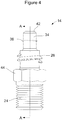
- the port component 14 further includes an integrally formed nut 44.
- the nut 44 enables the port component 14 to be threaded into a mating threaded bore in the wellhead using a conventional open end wrench and tightened securely.
- the upper threaded portion 28 in this example comprises a buttress thread, and it will be appreciated that the threads 30 on the inside surface 32 of the cap element 16 also incorporates a matching buttress thread. While a buttress thread is preferable for making an excellent connection, it will be appreciated that the cap assembly 10 is not limited to use with any one particular style of thread.
- the technician In operation, when a technician needs to check a gas flow rate at a wellhead that the cap assembly 10 is attached to, the technician would unscrew the cap component 12 from the port component 14. This can be done easily by hand.
- the tether 20 allows the cap component 12 to hang free while the technician slips the end of an external flexible (rubber or plastic) hose over the barb 36 on the upper neck portion 34.
- the barb 36 may be a soft barb which allows easily pushing the external hose onto the upper neck portion 34 and easy removal from the upper neck portion. The soft nature of the barb 36 ensures that virtually no wear and tear occurs on the inside surface of the external hose.
- the external hose can be slid off of the upper neck portion 34 and the cap component 12 can be threaded back onto the upper threaded portion 28 of the port component 14.
- the sealing element 38 will be engaging the upper edge 42 of the upper neck portion 34, thus sealing off the bore 26 of the port component 14 to ensure against any gas leakage.
- FIG. 5 shows a cap component 100 in accordance with another embodiment of the present disclosure.
- the cap component 100 is similar to cap component 12 and likewise includes a cap element 102 with a threaded inner surface 104 and a resilient (e.g., elastomeric) sealing element 106 (e.g., elastomeric) secured to an inner wall 108.
- the cap component 100 also includes a plug 110 preferably formed from a metallic material, for example from stainless steel or aluminum.
- the plug 110 has a diameter just slightly less than the diameter of bore portion 43 of the port component 14 (see Figure 3 ) so that it can be easily inserted into the bore portion 43, and so that there is only minimal clearance between the outer surface of the plug 110 and the inner surface of the bore portion 43.
- the plug 110 also preferably has a length such that it will extend into the port component 14, when the cap element 102 is fully threaded onto the port component 14, a significant portion of the length of the port component 14, or possibly even the entire length of the port component 14. This enables the plug 110 to protrude slightly into the path of the gas flowing through the wellhead.
- the plug 110 serves to conduct heat from the warm gas flowing through the wellhead to the inner surface of the bore portion 43 of the port component 14, to thus warm the port component 14, and thus prevent the buildup and blocking of the bore portion 43 with ice. In this regard it will be appreciated that freezing can occur when condensation inside the port component 14 freezes. If this occurs, the technician must first remove the blockage before he/she can attach the external hose of the measurement device to take gas flow readings.
- the length of the plug 110 will dictate the length of the tether 20 that is needed, since the tether needs to be sufficiently long to allow the plug 110 to be manipulated into and out from the port component 14.
- the plug 110 may be insert molded with the cap element 102 or attached to the cap component in any other suitable manner.
- the cap assembly 10 and its various embodiments discussed herein all provide a convenient, relatively inexpensive means for both closing off and allowing quick and easy access to a wellhead for gas flow sampling purposes.
- the cap assembly 10 can be installed in existing wellheads which have a threaded port for accepting the port component 14, and without any modification being required to the wellhead.
- the cap assembly 10 and its different embodiments make it even quicker and easier for the technician to attach gas flow measurement equipment to a wellhead to perform gas flow measurements.
Landscapes
- Engineering & Computer Science (AREA)
- Environmental & Geological Engineering (AREA)
- Mining & Mineral Resources (AREA)
- Life Sciences & Earth Sciences (AREA)
- Geology (AREA)
- Fluid Mechanics (AREA)
- Physics & Mathematics (AREA)
- General Life Sciences & Earth Sciences (AREA)
- Geochemistry & Mineralogy (AREA)
- Pipe Accessories (AREA)
- Pressure Vessels And Lids Thereof (AREA)
- Sampling And Sample Adjustment (AREA)
- Protection Of Pipes Against Damage, Friction, And Corrosion (AREA)
- Lining And Supports For Tunnels (AREA)
Description
- The present disclosure relates to caps and like systems used for allowing a gas quality, pressure and flow checking instrument to be temporarily connected to a landfill gas system wellhead port to check the pressures and/or a rate of flow of gas through the wellhead. More particularly, the present disclosure relates to a new cap assembly that enables secure sealing of a cap component to a port component, and which further allows easy attachment of an external flexible hose to the port component when sampling needs to be performed, and which is able to more positively seal an orifice of the port component.
- Landfill gas wells typically have a port component to which an external gas flow rate sensing device may be temporarily attached, as can be seen for example in documents
US 5 701 953 A ,US 2008/0127726 A1 orUS 2004/0177672 A1 . Typically these port components make use of one or more barbs formed on an outer surface of the port. An elastomeric cap component is slid over the port component to close off the port thereof. When a technician needs to check the gas flow through the wellhead, the cap component is slidably removed from the port component and an external rubber or plastic hose is attached to the port component. An opposite end of the hose is connected to an external gas quality, pressure and flow measurement device. When the technician is done making the gas (flow) measurements he/she would typically remove the hose that was used with the measurement device, and slide the cap component back over the barbs on the port component. Thus, the barbs sealing with the inside surface of the cap component is how a seal is achieved. - The above arrangement of a cap component making contact with the barbs on the port component has some drawbacks. For one, to achieve satisfactory sealing, there has to be an extremely tight fit between the cap component and the barbs, since this is where the actual sealing takes place. This often requires such a tight fit that the cap component can be difficult to slide on and off the port component. This is especially true in cold climates, where the rubber or plastic cap component may lose some of its stretchability. The very tight fit required also can result in rapid wear of the material on the inside surface of the cap component where contact with the barbs is made, which can lead to leaks of atmospheric air into the vacuum condition in the landfill gas collection wellhead and thereby degrade the energy and reuse value of the recovered gas. And the wear may not be that noticeable to the technician, so the possibility arises that the cap component inner surface may not be making a perfectly air tight seal with the port component, but this fact is not immediately detectable by the technician.
- Still another drawback is that present day cap components used with wellhead structures are not able to seal an orifice of the port component to prevent freezing and blockage of the orifice during the winter months in cold climate areas. Freezing occurs when condensation occurs in the orifice and the condensation freezes. When this occurs, a technician must spend extra time unblocking the orifice before measurements can be taken through the port component. A cap assembly that can help prevent freezing and blockage of the orifice of the port component would therefore be highly desirable.
-
WO 2011/006631 discloses an opening and closing device for a container in flexible material intended for the packaging of fluid products, the device comprising a pourer body and an opening and closing element associated removably with said pourer body. The device comprises further a base, substantially flattened and shaped so that it can be folded around a perimetric portion of predetermined external profile of said pourer body and can be sealed peripherally thereto, said base being intended to be sealed below to a predetermined portion of said flexible container provided with an aperture or which can be opened so as to bring into fluid communication said pourer body with the internal volume of said flexible container. - The present invention provides a well cap assembly for use with a wellhead, as defined in claim 1.
- The drawings described herein are for illustration purposes only and are not intended to limit the scope of the present disclosure in any way.
-
Figure 1 is a side elevational view of one embodiment of a well cap assembly in accordance with the present disclosure, where a cap component of the assembly is secured to a port component of the assembly; -
Figure 2 is view of the cap assembly ofFigure 1 but with the cap assembly rotated 90 degrees from the view shown inFigure 1 to better illustrate a tether that holds the cap component to the port component; -
Figure 3 is a cross sectional side view taken in accordance with section line A-A inFigure 2 showing the cap component sealingly engaged with the port component; -
Figure 4 is a side elevation view of just the port component of the well cap assembly; and -
Figure 5 is a side cross sectional view of another embodiment of the cap component of the well cap assembly that incorporates a plug. - The following description is merely exemplary in nature and is not intended to limit the present disclosure, application, or uses. It should be understood that throughout the drawings, corresponding reference numerals indicate like or corresponding parts and features.
- Referring to
Figures 1 and2 , a wellcap assembly 10 is shown in accordance with one embodiment of the present disclosure. The wellcap assembly 10 may include acap component 12 and aport component 14. Thecap component 12 may include acap element 16 having aretaining button 18 around which oneend 21 of atether 20 may be secured. The other end of thetether 20 may form aloop 22 that is wrapped around theport component 14 so as not to be removable from the port component once the port component is physically attached to a well head structure (not shown). - The
port component 14 includes a threadedportion 24 which can be threadably attached to a threaded bore in the wellhead. As shown inFigure 3 , theport component 14 includes abore 26 and an upper threadedportion 28. The upper threadedportion 28 is configured to engage withmating threads 30 formed on aninside surface 32 of thecap element 16. The diameter of the opening formed by thethreads 30 is sufficient to allow thecap element 16 to be placed over anupper neck portion 34 of theport component 14 without interference from the upper threadedportion 28. Theupper neck portion 34 may include one ormore barbs 36, which in one embodiment are "soft" barbs. By "soft" barbs it is meant barbs that are not aggressively shaped. The singlesoft barb 36 illustrated inFigure 3 is essentially a semicircular shaped ridge that protrudes from theupper neck portion 34 about the entire circumference of the upper neck portion. - The
cap component 12 may also include asealing element 38 secured, for example by suitable adhesives, to an innerupper end 40 of thecap component 12. Thesealing element 38 may comprise an elastomeric component that has some degree of resiliency so that it is able to deform slightly and seal against anupper edge 42 of theupper neck portion 34 when thecap component 12 is tightly threaded onto theport component 14. This serves to provide an excellent seal to ensure no leakage of gas occurs out from the well head to which theport component 14 is attached. - With reference to
Figures 3 and4 , theport component 14 further includes an integrally formednut 44. Thenut 44 enables theport component 14 to be threaded into a mating threaded bore in the wellhead using a conventional open end wrench and tightened securely. The upper threadedportion 28 in this example comprises a buttress thread, and it will be appreciated that thethreads 30 on theinside surface 32 of thecap element 16 also incorporates a matching buttress thread. While a buttress thread is preferable for making an excellent connection, it will be appreciated that thecap assembly 10 is not limited to use with any one particular style of thread. - In operation, when a technician needs to check a gas flow rate at a wellhead that the
cap assembly 10 is attached to, the technician would unscrew thecap component 12 from theport component 14. This can be done easily by hand. Thetether 20 allows thecap component 12 to hang free while the technician slips the end of an external flexible (rubber or plastic) hose over thebarb 36 on theupper neck portion 34. As noted above, thebarb 36 may be a soft barb which allows easily pushing the external hose onto theupper neck portion 34 and easy removal from the upper neck portion. The soft nature of thebarb 36 ensures that virtually no wear and tear occurs on the inside surface of the external hose. When the technician is done making measurements, the external hose can be slid off of theupper neck portion 34 and thecap component 12 can be threaded back onto the upper threadedportion 28 of theport component 14. Once thecap component 12 is fully threaded onto theport component 14, thesealing element 38 will be engaging theupper edge 42 of theupper neck portion 34, thus sealing off thebore 26 of theport component 14 to ensure against any gas leakage. This arrangement is expected to provide an even better seal than simply sliding a piece of hose or tubing over the end of a conventionally barbed port, as is typically presently done with conventional port components used with landfill gas wellheads. -
Figure 5 shows acap component 100 in accordance with another embodiment of the present disclosure. Thecap component 100 is similar tocap component 12 and likewise includes acap element 102 with a threadedinner surface 104 and a resilient (e.g., elastomeric) sealing element 106 (e.g., elastomeric) secured to aninner wall 108. Thecap component 100, however, also includes aplug 110 preferably formed from a metallic material, for example from stainless steel or aluminum. Theplug 110 has a diameter just slightly less than the diameter ofbore portion 43 of the port component 14 (seeFigure 3 ) so that it can be easily inserted into thebore portion 43, and so that there is only minimal clearance between the outer surface of theplug 110 and the inner surface of thebore portion 43. Theplug 110 also preferably has a length such that it will extend into theport component 14, when thecap element 102 is fully threaded onto theport component 14, a significant portion of the length of theport component 14, or possibly even the entire length of theport component 14. This enables theplug 110 to protrude slightly into the path of the gas flowing through the wellhead. Theplug 110 serves to conduct heat from the warm gas flowing through the wellhead to the inner surface of thebore portion 43 of theport component 14, to thus warm theport component 14, and thus prevent the buildup and blocking of thebore portion 43 with ice. In this regard it will be appreciated that freezing can occur when condensation inside theport component 14 freezes. If this occurs, the technician must first remove the blockage before he/she can attach the external hose of the measurement device to take gas flow readings. It will also be appreciated that the length of theplug 110 will dictate the length of thetether 20 that is needed, since the tether needs to be sufficiently long to allow theplug 110 to be manipulated into and out from theport component 14. Theplug 110 may be insert molded with thecap element 102 or attached to the cap component in any other suitable manner. - The
cap assembly 10 and its various embodiments discussed herein all provide a convenient, relatively inexpensive means for both closing off and allowing quick and easy access to a wellhead for gas flow sampling purposes. Thecap assembly 10 can be installed in existing wellheads which have a threaded port for accepting theport component 14, and without any modification being required to the wellhead. Thecap assembly 10 and its different embodiments make it even quicker and easier for the technician to attach gas flow measurement equipment to a wellhead to perform gas flow measurements.
Claims (10)
- A well cap assembly (10) for use with a wellhead, the wellhead enabling a fluid extracted from a well to flow therethrough, the well cap assembly (10) comprising:a port component (14) having:a bore (26) extending therethrough;an upper neck portion (34);an upper threaded portion (28) formed adjacent the upper neck portion (34), the upper neck portion (34) having a diameter which is less than a diameter formed by the upper threaded portion (28);a lower threaded portion (24);a circumferential barb (36) formed on the upper neck portion (34) configured to slidably receive an external flexible tube which is temporarily secured over the upper neck portion (34), to thus form a generally leak proof connection with the external flexible tube; anda cap element (16) having an internally threaded portion (30) for threadably engaging with the upper threaded portion (28) of the upper neck portion (34) and sealing the bore (26) of the port component (14).
- The well cap assembly (10) of claim 1, further comprising a tether (20) for securing the cap element (16) to the port component (14) while still permitting rotational movement of the cap element (16) relative to the port component (14).
- The well cap assembly (10) of claim 2, further comprising a resilient sealing component (38) affixed to an inner upper end (40) of the cap element (16), for engaging an upper edge of the upper neck portion (34) when the cap element (16) is tightened onto the upper threaded portion (28) of the upper neck portion (34).
- The well cap assembly (10) of claim 2 or claim 3, wherein the cap element (16) includes a retaining button (18) for retaining a first end of the tether (20) to the cap element (16).
- The well cap assembly (10) of any one of claims 2 to 4, wherein a second end of the tether (20) forms a loop (22) disposed around the port component (14) adjacent the lower threaded portion (24).
- The well cap assembly (10) of any one of the preceding claims, wherein the port component (14) includes an integrally formed nut (44) adjacent the lower threaded portion (24) for enabling an open end wrench to be used to engage the integrally formed nut (44) and to thread the port component (14) into a threaded bore in the wellhead.
- The well cap assembly (10) of any one of the preceding claims, wherein the upper threaded portion (28) of the port component (14) comprises a buttress thread.
- The well cap assembly (10) of any one of the preceding claims, further comprising an elongated plug (110) extending perpendicular from an inner upper end (108) of the cap element (16) and aligned coaxially with an axial center of the cap element (16), the elongated plug (110) having a length sufficiently long to extend through into a flow path of fluid flowing through the wellhead when the cap element (16) is attached to the port component (14).
- The well cap assembly (10) of claim 8, wherein the elongated plug (110) is comprised of a metallic material.
- The well cap assembly (10) of claim 8, wherein the elongated plug (110) is comprised of at least one of stainless steel or aluminum.
Applications Claiming Priority (2)
| Application Number | Priority Date | Filing Date | Title |
|---|---|---|---|
| US201462033836P | 2014-08-06 | 2014-08-06 | |
| PCT/US2015/043788 WO2016022669A1 (en) | 2014-08-06 | 2015-08-05 | Landfill gas wellhead cap assembly |
Publications (3)
| Publication Number | Publication Date |
|---|---|
| EP3177410A1 EP3177410A1 (en) | 2017-06-14 |
| EP3177410A4 EP3177410A4 (en) | 2018-04-18 |
| EP3177410B1 true EP3177410B1 (en) | 2018-11-28 |
Family
ID=55264489
Family Applications (1)
| Application Number | Title | Priority Date | Filing Date |
|---|---|---|---|
| EP15830051.7A Not-in-force EP3177410B1 (en) | 2014-08-06 | 2015-08-05 | Landfill gas wellhead cap assembly |
Country Status (8)
| Country | Link |
|---|---|
| US (1) | US10307805B2 (en) |
| EP (1) | EP3177410B1 (en) |
| CN (1) | CN106660084B (en) |
| AU (1) | AU2015301069B2 (en) |
| BR (1) | BR112017002240A2 (en) |
| CA (1) | CA2957027C (en) |
| ES (1) | ES2708335T3 (en) |
| WO (1) | WO2016022669A1 (en) |
Families Citing this family (1)
| Publication number | Priority date | Publication date | Assignee | Title |
|---|---|---|---|---|
| CN114405587A (en) * | 2022-03-08 | 2022-04-29 | 连云港浩森矿产品有限公司 | Silicon micro-powder grinding device with good environment-friendly effect and using method thereof |
Citations (2)
| Publication number | Priority date | Publication date | Assignee | Title |
|---|---|---|---|---|
| US5701953A (en) * | 1996-05-29 | 1997-12-30 | Ch2M Hill, Inc. | Well head for environmental extraction wells |
| US20080127726A1 (en) * | 2006-12-05 | 2008-06-05 | Elkins Earth Works, Llc | Portable gas monitor |
Family Cites Families (12)
| Publication number | Priority date | Publication date | Assignee | Title |
|---|---|---|---|---|
| US3458050A (en) * | 1968-09-10 | 1969-07-29 | Pall Corp | Frustoconical filter fittings |
| US4702754A (en) * | 1986-04-04 | 1987-10-27 | Blocker William C | Vapor delivery pressure test adapter |
| US4817450A (en) * | 1987-11-30 | 1989-04-04 | Spedco, Inc. | Pressure/temperature test plug assembly |
| US5063519A (en) * | 1989-09-18 | 1991-11-05 | Pacific Energy | Landfill gas production testing and extraction method |
| US6257626B1 (en) * | 1999-04-27 | 2001-07-10 | Flow-Rite Controls, Ltd. | Connector for fluid handling system |
| US7281439B2 (en) | 2003-03-13 | 2007-10-16 | Hvoc, L.L.C. | Volatile organic compound monitoring |
| US7568737B2 (en) * | 2006-09-22 | 2009-08-04 | Eaton Corporation | Male coupling for connecting to female threaded coupling |
| JP5021323B2 (en) * | 2007-01-25 | 2012-09-05 | 東洋製罐株式会社 | Inspection container |
| JP5129599B2 (en) * | 2007-05-08 | 2013-01-30 | 日本特殊陶業株式会社 | Gas sensor and manufacturing method thereof |
| US8245870B2 (en) * | 2008-03-18 | 2012-08-21 | Rubbermaid Incorporated | Container cap with tether |
| IT1394738B1 (en) * | 2009-07-13 | 2012-07-13 | Grc Pack Luxembourg S A | OPENING AND CLOSING DEVICE FOR FLEXIBLE MATERIAL CONTAINERS INTENDED FOR THE PACKAGING OF FLUID PRODUCTS, INCLUDING A FLEXIBLE CONTAINER AND SUCH A CLOSING AND METHOD OF PACKAGING A FLUID PRODUCT IN SUCH A PACKAGE |
| US9027769B2 (en) * | 2009-12-02 | 2015-05-12 | Amphipod, Inc. | Cap with integrated spout |
-
2015
- 2015-08-05 CN CN201580041793.4A patent/CN106660084B/en active Active
- 2015-08-05 EP EP15830051.7A patent/EP3177410B1/en not_active Not-in-force
- 2015-08-05 AU AU2015301069A patent/AU2015301069B2/en active Active
- 2015-08-05 ES ES15830051T patent/ES2708335T3/en active Active
- 2015-08-05 BR BR112017002240A patent/BR112017002240A2/en not_active Application Discontinuation
- 2015-08-05 WO PCT/US2015/043788 patent/WO2016022669A1/en not_active Ceased
- 2015-08-05 CA CA2957027A patent/CA2957027C/en not_active Expired - Fee Related
- 2015-08-05 US US15/500,774 patent/US10307805B2/en active Active
Patent Citations (2)
| Publication number | Priority date | Publication date | Assignee | Title |
|---|---|---|---|---|
| US5701953A (en) * | 1996-05-29 | 1997-12-30 | Ch2M Hill, Inc. | Well head for environmental extraction wells |
| US20080127726A1 (en) * | 2006-12-05 | 2008-06-05 | Elkins Earth Works, Llc | Portable gas monitor |
Also Published As
| Publication number | Publication date |
|---|---|
| US20170216894A1 (en) | 2017-08-03 |
| AU2015301069A1 (en) | 2017-02-02 |
| CN106660084A (en) | 2017-05-10 |
| AU2015301069B2 (en) | 2019-10-10 |
| CA2957027A1 (en) | 2016-02-11 |
| CA2957027C (en) | 2022-05-17 |
| WO2016022669A1 (en) | 2016-02-11 |
| CN106660084B (en) | 2019-12-10 |
| EP3177410A4 (en) | 2018-04-18 |
| EP3177410A1 (en) | 2017-06-14 |
| US10307805B2 (en) | 2019-06-04 |
| ES2708335T3 (en) | 2019-04-09 |
| BR112017002240A2 (en) | 2018-01-16 |
Similar Documents
| Publication | Publication Date | Title |
|---|---|---|
| CA2582655C (en) | Pipe clamp with built in test fitting | |
| US7984933B2 (en) | Multi-use torque fitting and compressible ferrule | |
| US9279526B2 (en) | Apparatuses and methods for providing finger-tightened and ratchet-secured connections between conduits | |
| US9475625B2 (en) | Closure system and method for resealing a caulking tube nozzle | |
| AU2003294711A1 (en) | Protective cap for a sealing stopper on a container for a capacitor | |
| WO2007139908A2 (en) | Temporary attachment tire pressure gauge | |
| US7677270B2 (en) | Plug for a hydraulic fitting | |
| US20160223097A1 (en) | Mounting assembly for mounting an adapter to a valve stem | |
| CN101730619B (en) | Tire sealing device | |
| CN109661532A (en) | Pipe joints and locking members | |
| US20140049042A1 (en) | Quick-connect assembly for a fluid valve | |
| JP2012197597A (en) | Pipe piercing tool and pipe piercing method | |
| KR101717808B1 (en) | Measuring needle with non return valve function | |
| CA2957027C (en) | Landfill gas wellhead cap assembly | |
| US20070169326A1 (en) | Bottle cap with integrated valve core remover | |
| AU642556B2 (en) | Mating core probe valve and retainer | |
| US20100012212A1 (en) | Apparatus for pressure testing a plumbing installation | |
| US9109738B2 (en) | Sealing plug for quick closing coupling system | |
| US20160325888A1 (en) | Tube Passage Sealing System | |
| KR101200263B1 (en) | Ball Valve Comprising Locking Device | |
| US6116262A (en) | Plumbing coupling and method of use | |
| DE502005006498D1 (en) | LOCKING DEVICE WITH PRESSURE VALVE | |
| JPH047438Y2 (en) | ||
| US20170223909A1 (en) | Combination maple fitting involving a plug on one end and a cap on the other end with a mounting clip on the side | |
| US20090091127A1 (en) | Saddle end cap |
Legal Events
| Date | Code | Title | Description |
|---|---|---|---|
| STAA | Information on the status of an ep patent application or granted ep patent |
Free format text: STATUS: THE INTERNATIONAL PUBLICATION HAS BEEN MADE |
|
| PUAI | Public reference made under article 153(3) epc to a published international application that has entered the european phase |
Free format text: ORIGINAL CODE: 0009012 |
|
| STAA | Information on the status of an ep patent application or granted ep patent |
Free format text: STATUS: REQUEST FOR EXAMINATION WAS MADE |
|
| 17P | Request for examination filed |
Effective date: 20170306 |
|
| AK | Designated contracting states |
Kind code of ref document: A1 Designated state(s): AL AT BE BG CH CY CZ DE DK EE ES FI FR GB GR HR HU IE IS IT LI LT LU LV MC MK MT NL NO PL PT RO RS SE SI SK SM TR |
|
| AX | Request for extension of the european patent |
Extension state: BA ME |
|
| DAV | Request for validation of the european patent (deleted) | ||
| DAX | Request for extension of the european patent (deleted) | ||
| A4 | Supplementary search report drawn up and despatched |
Effective date: 20180319 |
|
| RIC1 | Information provided on ipc code assigned before grant |
Ipc: B65D 41/02 20060101ALI20180313BHEP Ipc: E21B 33/03 20060101ALI20180313BHEP Ipc: B65D 55/16 20060101ALI20180313BHEP Ipc: B65D 41/04 20060101ALI20180313BHEP Ipc: B09B 1/00 20060101AFI20180313BHEP Ipc: B09B 5/00 20060101ALI20180313BHEP Ipc: B21B 33/02 20060101ALI20180313BHEP |
|
| GRAP | Despatch of communication of intention to grant a patent |
Free format text: ORIGINAL CODE: EPIDOSNIGR1 |
|
| STAA | Information on the status of an ep patent application or granted ep patent |
Free format text: STATUS: GRANT OF PATENT IS INTENDED |
|
| INTG | Intention to grant announced |
Effective date: 20180704 |
|
| GRAS | Grant fee paid |
Free format text: ORIGINAL CODE: EPIDOSNIGR3 |
|
| GRAA | (expected) grant |
Free format text: ORIGINAL CODE: 0009210 |
|
| STAA | Information on the status of an ep patent application or granted ep patent |
Free format text: STATUS: THE PATENT HAS BEEN GRANTED |
|
| AK | Designated contracting states |
Kind code of ref document: B1 Designated state(s): AL AT BE BG CH CY CZ DE DK EE ES FI FR GB GR HR HU IE IS IT LI LT LU LV MC MK MT NL NO PL PT RO RS SE SI SK SM TR |
|
| REG | Reference to a national code |
Ref country code: CH Ref legal event code: EP |
|
| REG | Reference to a national code |
Ref country code: AT Ref legal event code: REF Ref document number: 1069628 Country of ref document: AT Kind code of ref document: T Effective date: 20181215 |
|
| REG | Reference to a national code |
Ref country code: DE Ref legal event code: R096 Ref document number: 602015020632 Country of ref document: DE |
|
| REG | Reference to a national code |
Ref country code: IE Ref legal event code: FG4D |
|
| REG | Reference to a national code |
Ref country code: NL Ref legal event code: FP |
|
| REG | Reference to a national code |
Ref country code: ES Ref legal event code: FG2A Ref document number: 2708335 Country of ref document: ES Kind code of ref document: T3 Effective date: 20190409 |
|
| REG | Reference to a national code |
Ref country code: LT Ref legal event code: MG4D |
|
| REG | Reference to a national code |
Ref country code: AT Ref legal event code: MK05 Ref document number: 1069628 Country of ref document: AT Kind code of ref document: T Effective date: 20181128 |
|
| PG25 | Lapsed in a contracting state [announced via postgrant information from national office to epo] |
Ref country code: NO Free format text: LAPSE BECAUSE OF FAILURE TO SUBMIT A TRANSLATION OF THE DESCRIPTION OR TO PAY THE FEE WITHIN THE PRESCRIBED TIME-LIMIT Effective date: 20190228 Ref country code: AT Free format text: LAPSE BECAUSE OF FAILURE TO SUBMIT A TRANSLATION OF THE DESCRIPTION OR TO PAY THE FEE WITHIN THE PRESCRIBED TIME-LIMIT Effective date: 20181128 Ref country code: FI Free format text: LAPSE BECAUSE OF FAILURE TO SUBMIT A TRANSLATION OF THE DESCRIPTION OR TO PAY THE FEE WITHIN THE PRESCRIBED TIME-LIMIT Effective date: 20181128 Ref country code: IS Free format text: LAPSE BECAUSE OF FAILURE TO SUBMIT A TRANSLATION OF THE DESCRIPTION OR TO PAY THE FEE WITHIN THE PRESCRIBED TIME-LIMIT Effective date: 20190328 Ref country code: BG Free format text: LAPSE BECAUSE OF FAILURE TO SUBMIT A TRANSLATION OF THE DESCRIPTION OR TO PAY THE FEE WITHIN THE PRESCRIBED TIME-LIMIT Effective date: 20190228 Ref country code: LT Free format text: LAPSE BECAUSE OF FAILURE TO SUBMIT A TRANSLATION OF THE DESCRIPTION OR TO PAY THE FEE WITHIN THE PRESCRIBED TIME-LIMIT Effective date: 20181128 Ref country code: HR Free format text: LAPSE BECAUSE OF FAILURE TO SUBMIT A TRANSLATION OF THE DESCRIPTION OR TO PAY THE FEE WITHIN THE PRESCRIBED TIME-LIMIT Effective date: 20181128 Ref country code: LV Free format text: LAPSE BECAUSE OF FAILURE TO SUBMIT A TRANSLATION OF THE DESCRIPTION OR TO PAY THE FEE WITHIN THE PRESCRIBED TIME-LIMIT Effective date: 20181128 |
|
| PG25 | Lapsed in a contracting state [announced via postgrant information from national office to epo] |
Ref country code: RS Free format text: LAPSE BECAUSE OF FAILURE TO SUBMIT A TRANSLATION OF THE DESCRIPTION OR TO PAY THE FEE WITHIN THE PRESCRIBED TIME-LIMIT Effective date: 20181128 Ref country code: AL Free format text: LAPSE BECAUSE OF FAILURE TO SUBMIT A TRANSLATION OF THE DESCRIPTION OR TO PAY THE FEE WITHIN THE PRESCRIBED TIME-LIMIT Effective date: 20181128 Ref country code: SE Free format text: LAPSE BECAUSE OF FAILURE TO SUBMIT A TRANSLATION OF THE DESCRIPTION OR TO PAY THE FEE WITHIN THE PRESCRIBED TIME-LIMIT Effective date: 20181128 Ref country code: GR Free format text: LAPSE BECAUSE OF FAILURE TO SUBMIT A TRANSLATION OF THE DESCRIPTION OR TO PAY THE FEE WITHIN THE PRESCRIBED TIME-LIMIT Effective date: 20190301 Ref country code: PT Free format text: LAPSE BECAUSE OF FAILURE TO SUBMIT A TRANSLATION OF THE DESCRIPTION OR TO PAY THE FEE WITHIN THE PRESCRIBED TIME-LIMIT Effective date: 20190328 |
|
| PG25 | Lapsed in a contracting state [announced via postgrant information from national office to epo] |
Ref country code: DK Free format text: LAPSE BECAUSE OF FAILURE TO SUBMIT A TRANSLATION OF THE DESCRIPTION OR TO PAY THE FEE WITHIN THE PRESCRIBED TIME-LIMIT Effective date: 20181128 Ref country code: PL Free format text: LAPSE BECAUSE OF FAILURE TO SUBMIT A TRANSLATION OF THE DESCRIPTION OR TO PAY THE FEE WITHIN THE PRESCRIBED TIME-LIMIT Effective date: 20181128 Ref country code: CZ Free format text: LAPSE BECAUSE OF FAILURE TO SUBMIT A TRANSLATION OF THE DESCRIPTION OR TO PAY THE FEE WITHIN THE PRESCRIBED TIME-LIMIT Effective date: 20181128 |
|
| REG | Reference to a national code |
Ref country code: DE Ref legal event code: R097 Ref document number: 602015020632 Country of ref document: DE |
|
| PG25 | Lapsed in a contracting state [announced via postgrant information from national office to epo] |
Ref country code: RO Free format text: LAPSE BECAUSE OF FAILURE TO SUBMIT A TRANSLATION OF THE DESCRIPTION OR TO PAY THE FEE WITHIN THE PRESCRIBED TIME-LIMIT Effective date: 20181128 Ref country code: EE Free format text: LAPSE BECAUSE OF FAILURE TO SUBMIT A TRANSLATION OF THE DESCRIPTION OR TO PAY THE FEE WITHIN THE PRESCRIBED TIME-LIMIT Effective date: 20181128 Ref country code: SM Free format text: LAPSE BECAUSE OF FAILURE TO SUBMIT A TRANSLATION OF THE DESCRIPTION OR TO PAY THE FEE WITHIN THE PRESCRIBED TIME-LIMIT Effective date: 20181128 Ref country code: SK Free format text: LAPSE BECAUSE OF FAILURE TO SUBMIT A TRANSLATION OF THE DESCRIPTION OR TO PAY THE FEE WITHIN THE PRESCRIBED TIME-LIMIT Effective date: 20181128 |
|
| PGFP | Annual fee paid to national office [announced via postgrant information from national office to epo] |
Ref country code: NL Payment date: 20190826 Year of fee payment: 5 |
|
| PLBE | No opposition filed within time limit |
Free format text: ORIGINAL CODE: 0009261 |
|
| STAA | Information on the status of an ep patent application or granted ep patent |
Free format text: STATUS: NO OPPOSITION FILED WITHIN TIME LIMIT |
|
| PG25 | Lapsed in a contracting state [announced via postgrant information from national office to epo] |
Ref country code: SI Free format text: LAPSE BECAUSE OF FAILURE TO SUBMIT A TRANSLATION OF THE DESCRIPTION OR TO PAY THE FEE WITHIN THE PRESCRIBED TIME-LIMIT Effective date: 20181128 |
|
| PGFP | Annual fee paid to national office [announced via postgrant information from national office to epo] |
Ref country code: ES Payment date: 20190902 Year of fee payment: 5 Ref country code: IT Payment date: 20190826 Year of fee payment: 5 |
|
| 26N | No opposition filed |
Effective date: 20190829 |
|
| PG25 | Lapsed in a contracting state [announced via postgrant information from national office to epo] |
Ref country code: TR Free format text: LAPSE BECAUSE OF FAILURE TO SUBMIT A TRANSLATION OF THE DESCRIPTION OR TO PAY THE FEE WITHIN THE PRESCRIBED TIME-LIMIT Effective date: 20181128 |
|
| PG25 | Lapsed in a contracting state [announced via postgrant information from national office to epo] |
Ref country code: LI Free format text: LAPSE BECAUSE OF NON-PAYMENT OF DUE FEES Effective date: 20190831 Ref country code: MC Free format text: LAPSE BECAUSE OF FAILURE TO SUBMIT A TRANSLATION OF THE DESCRIPTION OR TO PAY THE FEE WITHIN THE PRESCRIBED TIME-LIMIT Effective date: 20181128 Ref country code: CH Free format text: LAPSE BECAUSE OF NON-PAYMENT OF DUE FEES Effective date: 20190831 Ref country code: LU Free format text: LAPSE BECAUSE OF NON-PAYMENT OF DUE FEES Effective date: 20190805 |
|
| REG | Reference to a national code |
Ref country code: BE Ref legal event code: MM Effective date: 20190831 |
|
| PG25 | Lapsed in a contracting state [announced via postgrant information from national office to epo] |
Ref country code: IE Free format text: LAPSE BECAUSE OF NON-PAYMENT OF DUE FEES Effective date: 20190805 |
|
| PG25 | Lapsed in a contracting state [announced via postgrant information from national office to epo] |
Ref country code: BE Free format text: LAPSE BECAUSE OF NON-PAYMENT OF DUE FEES Effective date: 20190831 |
|
| REG | Reference to a national code |
Ref country code: NL Ref legal event code: MM Effective date: 20200901 |
|
| PG25 | Lapsed in a contracting state [announced via postgrant information from national office to epo] |
Ref country code: CY Free format text: LAPSE BECAUSE OF FAILURE TO SUBMIT A TRANSLATION OF THE DESCRIPTION OR TO PAY THE FEE WITHIN THE PRESCRIBED TIME-LIMIT Effective date: 20181128 |
|
| PG25 | Lapsed in a contracting state [announced via postgrant information from national office to epo] |
Ref country code: MT Free format text: LAPSE BECAUSE OF FAILURE TO SUBMIT A TRANSLATION OF THE DESCRIPTION OR TO PAY THE FEE WITHIN THE PRESCRIBED TIME-LIMIT Effective date: 20181128 Ref country code: HU Free format text: LAPSE BECAUSE OF FAILURE TO SUBMIT A TRANSLATION OF THE DESCRIPTION OR TO PAY THE FEE WITHIN THE PRESCRIBED TIME-LIMIT; INVALID AB INITIO Effective date: 20150805 Ref country code: IT Free format text: LAPSE BECAUSE OF NON-PAYMENT OF DUE FEES Effective date: 20200805 |
|
| PG25 | Lapsed in a contracting state [announced via postgrant information from national office to epo] |
Ref country code: NL Free format text: LAPSE BECAUSE OF NON-PAYMENT OF DUE FEES Effective date: 20200901 |
|
| REG | Reference to a national code |
Ref country code: ES Ref legal event code: FD2A Effective date: 20211230 |
|
| PG25 | Lapsed in a contracting state [announced via postgrant information from national office to epo] |
Ref country code: ES Free format text: LAPSE BECAUSE OF NON-PAYMENT OF DUE FEES Effective date: 20200806 |
|
| PG25 | Lapsed in a contracting state [announced via postgrant information from national office to epo] |
Ref country code: MK Free format text: LAPSE BECAUSE OF FAILURE TO SUBMIT A TRANSLATION OF THE DESCRIPTION OR TO PAY THE FEE WITHIN THE PRESCRIBED TIME-LIMIT Effective date: 20181128 |
|
| P01 | Opt-out of the competence of the unified patent court (upc) registered |
Effective date: 20230621 |
|
| PGFP | Annual fee paid to national office [announced via postgrant information from national office to epo] |
Ref country code: GB Payment date: 20230828 Year of fee payment: 9 |
|
| PGFP | Annual fee paid to national office [announced via postgrant information from national office to epo] |
Ref country code: DE Payment date: 20230829 Year of fee payment: 9 Ref country code: FR Payment date: 20230825 Year of fee payment: 9 |
|
| REG | Reference to a national code |
Ref country code: DE Ref legal event code: R119 Ref document number: 602015020632 Country of ref document: DE |
|
| GBPC | Gb: european patent ceased through non-payment of renewal fee |
Effective date: 20240805 |
|
| PG25 | Lapsed in a contracting state [announced via postgrant information from national office to epo] |
Ref country code: DE Free format text: LAPSE BECAUSE OF NON-PAYMENT OF DUE FEES Effective date: 20250301 |
|
| PG25 | Lapsed in a contracting state [announced via postgrant information from national office to epo] |
Ref country code: GB Free format text: LAPSE BECAUSE OF NON-PAYMENT OF DUE FEES Effective date: 20240805 |
|
| PG25 | Lapsed in a contracting state [announced via postgrant information from national office to epo] |
Ref country code: FR Free format text: LAPSE BECAUSE OF NON-PAYMENT OF DUE FEES Effective date: 20240831 |