EP3176850A1 - Power storage module - Google Patents
Power storage module Download PDFInfo
- Publication number
- EP3176850A1 EP3176850A1 EP15828322.6A EP15828322A EP3176850A1 EP 3176850 A1 EP3176850 A1 EP 3176850A1 EP 15828322 A EP15828322 A EP 15828322A EP 3176850 A1 EP3176850 A1 EP 3176850A1
- Authority
- EP
- European Patent Office
- Prior art keywords
- electrical storage
- holding member
- fuse
- busbar
- storage unit
- Prior art date
- Legal status (The legal status is an assumption and is not a legal conclusion. Google has not performed a legal analysis and makes no representation as to the accuracy of the status listed.)
- Granted
Links
- 238000003860 storage Methods 0.000 title claims abstract description 246
- 238000001514 detection method Methods 0.000 claims abstract description 73
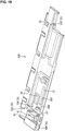
- 238000003466 welding Methods 0.000 description 45
- 229910052751 metal Inorganic materials 0.000 description 32
- 239000002184 metal Substances 0.000 description 32
- 230000001012 protector Effects 0.000 description 23
- 238000000034 method Methods 0.000 description 18
- 229910000838 Al alloy Inorganic materials 0.000 description 14
- PXHVJJICTQNCMI-UHFFFAOYSA-N Nickel Chemical compound [Ni] PXHVJJICTQNCMI-UHFFFAOYSA-N 0.000 description 14
- 229910052782 aluminium Inorganic materials 0.000 description 14
- XAGFODPZIPBFFR-UHFFFAOYSA-N aluminium Chemical compound [Al] XAGFODPZIPBFFR-UHFFFAOYSA-N 0.000 description 14
- RYGMFSIKBFXOCR-UHFFFAOYSA-N Copper Chemical compound [Cu] RYGMFSIKBFXOCR-UHFFFAOYSA-N 0.000 description 11
- 229910000881 Cu alloy Inorganic materials 0.000 description 11
- 229910052802 copper Inorganic materials 0.000 description 11
- 239000010949 copper Substances 0.000 description 11
- ATJFFYVFTNAWJD-UHFFFAOYSA-N Tin Chemical compound [Sn] ATJFFYVFTNAWJD-UHFFFAOYSA-N 0.000 description 7
- 229910052759 nickel Inorganic materials 0.000 description 7
- 238000003825 pressing Methods 0.000 description 7
- 239000000463 material Substances 0.000 description 6
- 230000000694 effects Effects 0.000 description 5
- 238000005219 brazing Methods 0.000 description 4
- 239000007769 metal material Substances 0.000 description 4
- 229920005989 resin Polymers 0.000 description 4
- 239000011347 resin Substances 0.000 description 4
- 238000005476 soldering Methods 0.000 description 4
- 239000000057 synthetic resin Substances 0.000 description 4
- 229920003002 synthetic resin Polymers 0.000 description 4
- 238000003780 insertion Methods 0.000 description 3
- 230000037431 insertion Effects 0.000 description 3
- 210000000078 claw Anatomy 0.000 description 2
- 239000004020 conductor Substances 0.000 description 2
- 238000006073 displacement reaction Methods 0.000 description 2
- 238000004519 manufacturing process Methods 0.000 description 2
- 238000004026 adhesive bonding Methods 0.000 description 1
- 238000005452 bending Methods 0.000 description 1
- 239000003990 capacitor Substances 0.000 description 1
- 238000002788 crimping Methods 0.000 description 1
- 239000011888 foil Substances 0.000 description 1
- 230000004927 fusion Effects 0.000 description 1
- 239000005001 laminate film Substances 0.000 description 1
- 230000000717 retained effect Effects 0.000 description 1
Images
























Classifications
-
- H—ELECTRICITY
- H01—ELECTRIC ELEMENTS
- H01G—CAPACITORS; CAPACITORS, RECTIFIERS, DETECTORS, SWITCHING DEVICES, LIGHT-SENSITIVE OR TEMPERATURE-SENSITIVE DEVICES OF THE ELECTROLYTIC TYPE
- H01G2/00—Details of capacitors not covered by a single one of groups H01G4/00-H01G11/00
- H01G2/14—Protection against electric or thermal overload
- H01G2/16—Protection against electric or thermal overload with fusing elements
-
- H—ELECTRICITY
- H01—ELECTRIC ELEMENTS
- H01G—CAPACITORS; CAPACITORS, RECTIFIERS, DETECTORS, SWITCHING DEVICES, LIGHT-SENSITIVE OR TEMPERATURE-SENSITIVE DEVICES OF THE ELECTROLYTIC TYPE
- H01G11/00—Hybrid capacitors, i.e. capacitors having different positive and negative electrodes; Electric double-layer [EDL] capacitors; Processes for the manufacture thereof or of parts thereof
- H01G11/10—Multiple hybrid or EDL capacitors, e.g. arrays or modules
- H01G11/12—Stacked hybrid or EDL capacitors
-
- H—ELECTRICITY
- H01—ELECTRIC ELEMENTS
- H01G—CAPACITORS; CAPACITORS, RECTIFIERS, DETECTORS, SWITCHING DEVICES, LIGHT-SENSITIVE OR TEMPERATURE-SENSITIVE DEVICES OF THE ELECTROLYTIC TYPE
- H01G11/00—Hybrid capacitors, i.e. capacitors having different positive and negative electrodes; Electric double-layer [EDL] capacitors; Processes for the manufacture thereof or of parts thereof
- H01G11/14—Arrangements or processes for adjusting or protecting hybrid or EDL capacitors
- H01G11/16—Arrangements or processes for adjusting or protecting hybrid or EDL capacitors against electric overloads, e.g. including fuses
-
- H—ELECTRICITY
- H01—ELECTRIC ELEMENTS
- H01G—CAPACITORS; CAPACITORS, RECTIFIERS, DETECTORS, SWITCHING DEVICES, LIGHT-SENSITIVE OR TEMPERATURE-SENSITIVE DEVICES OF THE ELECTROLYTIC TYPE
- H01G11/00—Hybrid capacitors, i.e. capacitors having different positive and negative electrodes; Electric double-layer [EDL] capacitors; Processes for the manufacture thereof or of parts thereof
- H01G11/74—Terminals, e.g. extensions of current collectors
- H01G11/76—Terminals, e.g. extensions of current collectors specially adapted for integration in multiple or stacked hybrid or EDL capacitors
-
- H—ELECTRICITY
- H01—ELECTRIC ELEMENTS
- H01G—CAPACITORS; CAPACITORS, RECTIFIERS, DETECTORS, SWITCHING DEVICES, LIGHT-SENSITIVE OR TEMPERATURE-SENSITIVE DEVICES OF THE ELECTROLYTIC TYPE
- H01G11/00—Hybrid capacitors, i.e. capacitors having different positive and negative electrodes; Electric double-layer [EDL] capacitors; Processes for the manufacture thereof or of parts thereof
- H01G11/78—Cases; Housings; Encapsulations; Mountings
- H01G11/82—Fixing or assembling a capacitive element in a housing, e.g. mounting electrodes, current collectors or terminals in containers or encapsulations
-
- H—ELECTRICITY
- H01—ELECTRIC ELEMENTS
- H01G—CAPACITORS; CAPACITORS, RECTIFIERS, DETECTORS, SWITCHING DEVICES, LIGHT-SENSITIVE OR TEMPERATURE-SENSITIVE DEVICES OF THE ELECTROLYTIC TYPE
- H01G2/00—Details of capacitors not covered by a single one of groups H01G4/00-H01G11/00
- H01G2/02—Mountings
- H01G2/04—Mountings specially adapted for mounting on a chassis
-
- H—ELECTRICITY
- H01—ELECTRIC ELEMENTS
- H01M—PROCESSES OR MEANS, e.g. BATTERIES, FOR THE DIRECT CONVERSION OF CHEMICAL ENERGY INTO ELECTRICAL ENERGY
- H01M10/00—Secondary cells; Manufacture thereof
- H01M10/42—Methods or arrangements for servicing or maintenance of secondary cells or secondary half-cells
- H01M10/48—Accumulators combined with arrangements for measuring, testing or indicating the condition of cells, e.g. the level or density of the electrolyte
- H01M10/482—Accumulators combined with arrangements for measuring, testing or indicating the condition of cells, e.g. the level or density of the electrolyte for several batteries or cells simultaneously or sequentially
-
- H—ELECTRICITY
- H01—ELECTRIC ELEMENTS
- H01M—PROCESSES OR MEANS, e.g. BATTERIES, FOR THE DIRECT CONVERSION OF CHEMICAL ENERGY INTO ELECTRICAL ENERGY
- H01M50/00—Constructional details or processes of manufacture of the non-active parts of electrochemical cells other than fuel cells, e.g. hybrid cells
- H01M50/10—Primary casings; Jackets or wrappings
- H01M50/172—Arrangements of electric connectors penetrating the casing
- H01M50/174—Arrangements of electric connectors penetrating the casing adapted for the shape of the cells
- H01M50/178—Arrangements of electric connectors penetrating the casing adapted for the shape of the cells for pouch or flexible bag cells
-
- H—ELECTRICITY
- H01—ELECTRIC ELEMENTS
- H01M—PROCESSES OR MEANS, e.g. BATTERIES, FOR THE DIRECT CONVERSION OF CHEMICAL ENERGY INTO ELECTRICAL ENERGY
- H01M50/00—Constructional details or processes of manufacture of the non-active parts of electrochemical cells other than fuel cells, e.g. hybrid cells
- H01M50/20—Mountings; Secondary casings or frames; Racks, modules or packs; Suspension devices; Shock absorbers; Transport or carrying devices; Holders
- H01M50/204—Racks, modules or packs for multiple batteries or multiple cells
- H01M50/207—Racks, modules or packs for multiple batteries or multiple cells characterised by their shape
- H01M50/211—Racks, modules or packs for multiple batteries or multiple cells characterised by their shape adapted for pouch cells
-
- H—ELECTRICITY
- H01—ELECTRIC ELEMENTS
- H01M—PROCESSES OR MEANS, e.g. BATTERIES, FOR THE DIRECT CONVERSION OF CHEMICAL ENERGY INTO ELECTRICAL ENERGY
- H01M50/00—Constructional details or processes of manufacture of the non-active parts of electrochemical cells other than fuel cells, e.g. hybrid cells
- H01M50/50—Current conducting connections for cells or batteries
- H01M50/543—Terminals
- H01M50/547—Terminals characterised by the disposition of the terminals on the cells
- H01M50/55—Terminals characterised by the disposition of the terminals on the cells on the same side of the cell
-
- H—ELECTRICITY
- H01—ELECTRIC ELEMENTS
- H01M—PROCESSES OR MEANS, e.g. BATTERIES, FOR THE DIRECT CONVERSION OF CHEMICAL ENERGY INTO ELECTRICAL ENERGY
- H01M50/00—Constructional details or processes of manufacture of the non-active parts of electrochemical cells other than fuel cells, e.g. hybrid cells
- H01M50/50—Current conducting connections for cells or batteries
- H01M50/543—Terminals
- H01M50/552—Terminals characterised by their shape
- H01M50/553—Terminals adapted for prismatic, pouch or rectangular cells
-
- H—ELECTRICITY
- H01—ELECTRIC ELEMENTS
- H01M—PROCESSES OR MEANS, e.g. BATTERIES, FOR THE DIRECT CONVERSION OF CHEMICAL ENERGY INTO ELECTRICAL ENERGY
- H01M50/00—Constructional details or processes of manufacture of the non-active parts of electrochemical cells other than fuel cells, e.g. hybrid cells
- H01M50/50—Current conducting connections for cells or batteries
- H01M50/569—Constructional details of current conducting connections for detecting conditions inside cells or batteries, e.g. details of voltage sensing terminals
-
- H—ELECTRICITY
- H01—ELECTRIC ELEMENTS
- H01M—PROCESSES OR MEANS, e.g. BATTERIES, FOR THE DIRECT CONVERSION OF CHEMICAL ENERGY INTO ELECTRICAL ENERGY
- H01M50/00—Constructional details or processes of manufacture of the non-active parts of electrochemical cells other than fuel cells, e.g. hybrid cells
- H01M50/50—Current conducting connections for cells or batteries
- H01M50/572—Means for preventing undesired use or discharge
- H01M50/574—Devices or arrangements for the interruption of current
- H01M50/581—Devices or arrangements for the interruption of current in response to temperature
-
- H—ELECTRICITY
- H01—ELECTRIC ELEMENTS
- H01M—PROCESSES OR MEANS, e.g. BATTERIES, FOR THE DIRECT CONVERSION OF CHEMICAL ENERGY INTO ELECTRICAL ENERGY
- H01M2200/00—Safety devices for primary or secondary batteries
- H01M2200/10—Temperature sensitive devices
- H01M2200/103—Fuse
-
- H—ELECTRICITY
- H01—ELECTRIC ELEMENTS
- H01M—PROCESSES OR MEANS, e.g. BATTERIES, FOR THE DIRECT CONVERSION OF CHEMICAL ENERGY INTO ELECTRICAL ENERGY
- H01M2220/00—Batteries for particular applications
- H01M2220/20—Batteries in motive systems, e.g. vehicle, ship, plane
-
- H—ELECTRICITY
- H01—ELECTRIC ELEMENTS
- H01M—PROCESSES OR MEANS, e.g. BATTERIES, FOR THE DIRECT CONVERSION OF CHEMICAL ENERGY INTO ELECTRICAL ENERGY
- H01M50/00—Constructional details or processes of manufacture of the non-active parts of electrochemical cells other than fuel cells, e.g. hybrid cells
- H01M50/50—Current conducting connections for cells or batteries
- H01M50/502—Interconnectors for connecting terminals of adjacent batteries; Interconnectors for connecting cells outside a battery casing
- H01M50/509—Interconnectors for connecting terminals of adjacent batteries; Interconnectors for connecting cells outside a battery casing characterised by the type of connection, e.g. mixed connections
- H01M50/51—Connection only in series
-
- H—ELECTRICITY
- H01—ELECTRIC ELEMENTS
- H01M—PROCESSES OR MEANS, e.g. BATTERIES, FOR THE DIRECT CONVERSION OF CHEMICAL ENERGY INTO ELECTRICAL ENERGY
- H01M50/00—Constructional details or processes of manufacture of the non-active parts of electrochemical cells other than fuel cells, e.g. hybrid cells
- H01M50/50—Current conducting connections for cells or batteries
- H01M50/502—Interconnectors for connecting terminals of adjacent batteries; Interconnectors for connecting cells outside a battery casing
- H01M50/514—Methods for interconnecting adjacent batteries or cells
- H01M50/516—Methods for interconnecting adjacent batteries or cells by welding, soldering or brazing
-
- Y—GENERAL TAGGING OF NEW TECHNOLOGICAL DEVELOPMENTS; GENERAL TAGGING OF CROSS-SECTIONAL TECHNOLOGIES SPANNING OVER SEVERAL SECTIONS OF THE IPC; TECHNICAL SUBJECTS COVERED BY FORMER USPC CROSS-REFERENCE ART COLLECTIONS [XRACs] AND DIGESTS
- Y02—TECHNOLOGIES OR APPLICATIONS FOR MITIGATION OR ADAPTATION AGAINST CLIMATE CHANGE
- Y02E—REDUCTION OF GREENHOUSE GAS [GHG] EMISSIONS, RELATED TO ENERGY GENERATION, TRANSMISSION OR DISTRIBUTION
- Y02E60/00—Enabling technologies; Technologies with a potential or indirect contribution to GHG emissions mitigation
- Y02E60/10—Energy storage using batteries
-
- Y—GENERAL TAGGING OF NEW TECHNOLOGICAL DEVELOPMENTS; GENERAL TAGGING OF CROSS-SECTIONAL TECHNOLOGIES SPANNING OVER SEVERAL SECTIONS OF THE IPC; TECHNICAL SUBJECTS COVERED BY FORMER USPC CROSS-REFERENCE ART COLLECTIONS [XRACs] AND DIGESTS
- Y02—TECHNOLOGIES OR APPLICATIONS FOR MITIGATION OR ADAPTATION AGAINST CLIMATE CHANGE
- Y02E—REDUCTION OF GREENHOUSE GAS [GHG] EMISSIONS, RELATED TO ENERGY GENERATION, TRANSMISSION OR DISTRIBUTION
- Y02E60/00—Enabling technologies; Technologies with a potential or indirect contribution to GHG emissions mitigation
- Y02E60/13—Energy storage using capacitors
-
- Y—GENERAL TAGGING OF NEW TECHNOLOGICAL DEVELOPMENTS; GENERAL TAGGING OF CROSS-SECTIONAL TECHNOLOGIES SPANNING OVER SEVERAL SECTIONS OF THE IPC; TECHNICAL SUBJECTS COVERED BY FORMER USPC CROSS-REFERENCE ART COLLECTIONS [XRACs] AND DIGESTS
- Y02—TECHNOLOGIES OR APPLICATIONS FOR MITIGATION OR ADAPTATION AGAINST CLIMATE CHANGE
- Y02T—CLIMATE CHANGE MITIGATION TECHNOLOGIES RELATED TO TRANSPORTATION
- Y02T10/00—Road transport of goods or passengers
- Y02T10/60—Other road transportation technologies with climate change mitigation effect
- Y02T10/70—Energy storage systems for electromobility, e.g. batteries
Definitions
- the present invention relates to an electrical storage module.
- battery modules mounted on, for example, electric cars or hybrid vehicles are constituted by connecting multiple electric cells in series or parallel with each other via busbars (see Patent Document 1, for example).
- a battery module includes detection terminals for detecting a state of the electric cells, and detection electric wires connected to the detection terminals.
- Patent Document 1 JP 2013-106400A
- An object of the present invention is to downsize an electrical storage module provided with fuses.
- an electrical storage module includes: an electrical storage element group in which a plurality of electrical storage elements are stacked on one another, each electrical storage element having lead terminals that protrude from a side edge of the electrical storage element; and fuses that are electrically connected to the lead terminals, wherein detection terminals for detecting a state of the electrical storage elements are directly connected to the fuses.
- the electrical storage module includes the fuses that are electrically connected to the lead terminals of the electrical storage elements, and the detection terminals are directly connected to the fuses.
- the present invention there is no need for fuse blocks for connecting the fuses and the detection terminals, or members for connecting the fuses and the detection terminals. Accordingly, it is possible to realize downsizing and to reduce the number of the components as compared with that of a conventional case.
- the present invention may have a configuration in which holding members that hold the lead terminals and fuse connecting busbars that electrically connect the fuses and the lead terminals, each holding member being provided with a fuse mounting part on which a fuse is mounted, and a terminal housing part in which a detection terminal is housed, wherein the fuses are electrically connected to the detection terminals and the electrical storage elements, by putting the electrical storage module into a state in which the fuses are mounted on the fuse mounting parts, the detection terminals are housed in the terminal housing parts, and the fuse connecting busbars and the lead terminals are connected to each other.
- the detection terminals may be connected to busbars via relay terminals.
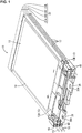
- FIGS. 1 to 34 An electrical storage module 10 according to Embodiment 1 will be described with reference to FIGS. 1 to 34 .
- FIGS. 1 to 34 there may be cases where reference signs are given to only one of a plurality of the same members and are not given to the remaining members.
- "front” and “rear” respectively refer to the left side and right side of FIG. 2 .
- the electrical storage module 10 of the present embodiment includes: an electrical storage element group 11 in which a plurality of (four in the present embodiment) electrical storage elements 12 are stacked on one another, each electrical storage element having lead terminals 13 that protrude from a side edge of the electrical storage element; and fuses 45 that are electrically connected to the lead terminals 13.
- the electrical storage module 10 further includes: holding members 30 that are respectively attached to the side edges at which the lead terminals 13 are provided, and hold the electrical storage elements 12; and fuse connecting busbars 40 that are connected to the lead terminals 13 and to the fuses 45.
- any electrical storage elements 12 such as secondary batteries, capacitors, and condensers may be used as needed as the electrical storage elements 12 constituting the electrical storage element group 11.
- secondary batteries are used as the electrical storage elements 12.
- the electrical storage module 10 includes: a stacked body 20 that is made of a stack of four electrical storage units 21 each obtained by placing the electrical storage element 12 on a heat transfer member 17 to which the holding members 30 are attached; and a case that is not shown.
- the four electrical storage units 21 that constitute the stacked body 20 are a first electrical storage unit 21A, a second electrical storage unit 21B, a third electrical storage unit 21C, and a fourth electrical storage unit 21D in the stated order from the bottom.
- Each of the electrical storage units 21 includes the holding members 30 attached to both ends in its longitudinal direction, the heat transfer member 17, and the electrical storage element 12.
- the heat transfer member 17 is a plate-shaped member made of a heat conductive material.
- aluminum or an aluminum alloy, which has excellent heat conductivity, is used as the heat conductive material.
- the holding members 30 made of an insulating resin material are attached to both ends in the longitudinal direction of the heat transfer member 17, and the electrical storage element 12 is placed on the upper surface of the heat transfer member 17.
- the electrical storage element 12 is substantially rectangular when viewed from above.
- the electrical storage element 12 includes: a container 14 obtained by welding side edges of a pair of substantially rectangular laminate films; an electrical storage component that is not shown and is contained in the inside of the container 14; and the lead terminals 13 that are connected to the electrical storage component inside the container 14 and are drawn from a side edge of the container 14 to the outside.
- the lead terminals 13 of positive and negative polarities are drawn from one side edge (front side edge) of the container 14.
- corner parts 15A at protruding ends of the lead terminals 13 are fitted to electrical storage element holding parts 31 of the holding member 30, so that displacement of the electrical storage element 12 is restricted.
- busbars 25 are connected by welding to the ends of the lead terminals 13 that are adjacent to each other in a stacking direction (vertical direction in FIG. 3 ), and the electrical storage elements 12 are electrically connected to each other via the busbars 25.
- external connection busbars 26 for connection to external devices are connected to the lead terminal 13 of the electrical storage element 12 of the first electrical storage unit 21A (electrical storage unit 21 in the lowermost stage), and to the lead terminal 13 of the electrical storage element 12 of the fourth electrical storage unit 21D (electrical storage unit 21 in the uppermost stage).
- the electrical storage elements 12 that are overlaid in the stacking direction are connected in series to each other by connecting the lead terminals 13 having opposite polarities to each other via the busbars 25.
- the lead terminals 13 include a positive lead terminal 13A and a negative lead terminal 13B.
- Metal fuse connecting busbars 40 to connect the fuses 45 and the lead terminals 13 are connected by welding to the lead terminals 13.
- the lead terminals 13 are made of aluminum or an aluminum alloy.
- the negative lead terminal 13B of the electrical storage element 12 is overlaid directly on and joined by welding to a first fuse connecting busbar 40A and the external connection busbar 26, which are arranged side by side on the holding member 30. Furthermore, in the first electrical storage unit 21A, the positive lead terminal 13A of the electrical storage element 12 is overlaid directly on and joined by welding to a second fuse connecting busbar 40B arranged on the holding member 30, and is joined by welding to the busbar 25 overlaid on this positive lead terminal 13A.
- the positive lead terminal 13A of the electrical storage element 12 is overlaid directly on and joined by welding to the fuse connecting busbar 40 arranged on the holding member 30, and is joined by welding to the busbar 25 overlaid on this positive lead terminal 13A (see FIGS. 17 and 24 ).
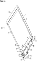
- the positive lead terminal 13A of the electrical storage element 12 is overlaid directly on and joined by welding to a third fuse connecting busbar 40C arranged sideways on the holding member 30, and is joined by welding to the external connection busbar 26 overlaid on this positive lead terminal 13A (see FIG. 30 ).
- Examples of the welding method include a laser welding method, an ultrasonic welding method, and the like.
- a holding member 30 of each electrical storage unit 21 is provided with electrical storage element holding parts 31 that are recessed and into which the corner parts 15A of the lead terminals 13 of the electrical storage element 12 are fitted.
- This electrical storage element holding parts 31 restrict the displacement of the lead terminals 13 (electrical storage element 12).
- the holding member 30 arranged on the front side is a first holding member 30A (see FIGS. 4 and 12 ), and the holding member 30 arranged on the rear side is a fifth holding member 30E (see FIG. 4 ).
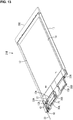
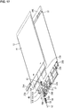
- the holding member 30 arranged on the front side is a second holding member 30B (see FIGS. 13 and 19 ), and the holding member 30 arranged on the rear side is the fifth holding member 30E (see FIG. 13 ).
- the holding member 30 arranged on the front side is a third holding member 30C (see FIGS. 20 and 25 ), and the holding member 30 arranged on the rear side is the fifth holding member 30E (see FIG. 20 ).
- the holding member 30 arranged on the front side is a fourth holding member 30D (see FIGS. 26 and 31 )
- the holding member 30 arranged on the rear side is the fifth holding member 30E (see FIG. 26 ).
- Each of the holding members 30A, 30B, 30C, and 30D arranged on the front side of the electrical storage units 21 includes a fuse mounting part 42 on which the fuse 45 is mounted, and a terminal housing part 48 in which the detection terminal 50 is housed, and holds the lead terminals 13 and the fuse connecting busbar 40 that electrically connects the fuse 45 and the lead terminal 13.
- Each holding member 30 is provided with a heat transfer member mounting part 32 into which the heat transfer member 17 is inserted and attached.
- the first holding member 30A has, at a position close to the right side of FIG. 12 , a positioning protrusion 33A for positioning the second holding member 30B.
- the second holding member 30B has, at the position close to the right side of FIG. 19 , a positioning hole 33B for receiving the positioning protrusion 33A of the first holding member 30A, and has, at the position close to the left side of the figure, a positioning protrusion 33A for positioning the third holding member 30C.
- the third holding member 30C has, at the position close to the left side of FIG. 25 , a positioning hole 33B for receiving the positioning protrusion 33A of the second holding member 30B, and has, at the position close to the right side of the figure, a positioning protrusion 33A for positioning the fourth holding member 30D.
- the fourth holding member 30D has, at the position close to the right side of FIG. 31 , a positioning hole 33B for receiving the positioning protrusion 33A of the third holding member 30C.
- the first holding member 30A has an engagement protrusion 34 that protrudes upward and engages with the second holding member 30B, and an engagement-receiving part 35 that receives and engages with the engagement protrusion 34 of the third holding member 30C.
- the second holding member 30B has an engagement-receiving part 35 that receives and engages with the engagement protrusion 34 of the first holding member 30A, and an engagement protrusion 34 that protrudes upward and engages with the fourth holding member 30D.
- the third holding member 30C has an engagement protrusion 34 that protrudes downward and engages with the engagement-receiving part 35 of the first holding member 30A.
- the fourth holding member 30D has an engagement-receiving part 35 that receives and engages with the engagement protrusion 34 of the second holding member 30B.
- the first holding member 30A, the second holding member 30B, the third holding member 30C, and the fourth holding member 30D are each provided with a connection member holding part 36 that holds the busbar 25 or the external connection busbar 26, and the lead terminal 13 in a state in which they are overlaid on each other.
- the connection member holding part 36 is provided with a recessed part 36A into which the busbar 25 or the external connection busbar 26 can be fitted, and a retaining protrusion 36B that retains the busbar 25 or the external connection busbar 26 that is fitted into the recessed part 36A.
- the first holding member 30A, the second holding member 30B, the third holding member 30C, and the fourth holding member 30D are each provided with a first welding hole 37 for use in welding and connecting the lead terminal 13 of the electrical storage element 12 to the connection member (the busbar 25 or the external connection busbar 26) to be connected to the lead terminal 13 of the electrical storage element 12 (see FIGS. 12 , 19 , 25 , and 31 ).
- the busbars 25 are made of aluminum or an aluminum alloy, and are arranged overlapping the lead terminals 13. As shown in FIG. 3 , the busbars 25 have a U-shaped cross section so that connection parts 25A connected to the lead terminals 13 are arranged at a distance in the vertical direction.
- the external connection busbars 26 are made of aluminum or an aluminum alloy, and are arranged overlapping the lead terminals 13. An end of each of the external connection busbars 26 protrudes frontward, and is provided with a connection hole 26A through which an external connection terminal (not shown) is to be connected thereto.
- the first holding member 30A, the second holding member 30B, the third holding member 30C, and the fourth holding member 30D are each provided with a busbar holding part 38 that holds the fuse connecting busbar 40, a fuse mounting part 42 on which the fuse 45 is mounted, and a terminal housing part 48 for housing the detection terminal 50 that is connected to the fuse 45.
- the fuse connecting busbar 40 held by the busbar holding part 38 has a terminal connection part 41A that is overlaid on and connected to the lead terminal 13, an extending part 41B that extends laterally from the terminal connection part 41A, and a tuning-fork terminal part 41C that is folded upward in the vertical direction relative to the extending part 41B, and is formed by being divided at an end into two portions.
- the fuse connecting busbar 40 is made of, for example, a metal material such as copper, a copper alloy, aluminum, or an aluminum alloy.
- the fuse 45 is interposed between the divided portions of the tuning-fork terminal part 41C, and is electrically connected to the tuning-fork terminal part 41C.
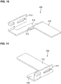
- fuse connecting busbars 40 Three types of the fuse connecting busbars 40, specifically, the first fuse connecting busbar 40A shown in FIG. 10 , the second fuse connecting busbar 40B shown in FIG. 11 , and the third fuse connecting busbar 40C shown in FIG. 18 , are used.
- the first fuse connecting busbar 40A is arranged under the negative lead terminal 13B of the first electrical storage unit 21A, and has a shape in which a step part 41D is formed between the terminal connection part 41A and the extending part 41B.
- the second fuse connecting busbars 40B are arranged under the positive lead terminal 13A of the first electrical storage unit 21A, and the positive lead terminal 13A of the third electrical storage unit 21C.
- the third fuse connecting busbars 40C are arranged under the positive lead terminal 13A of the second electrical storage unit 21B, and the positive lead terminal 13A of the fourth electrical storage unit 21D.
- the second fuse connecting busbar 40B and the third fuse connecting busbar 40C are symmetric, and do not have the step part 41D.
- the busbar holding part 38 has a recessed part 38A into which the terminal connection part 41A and the extending part 41B of the fuse connecting busbar 40 are fitted.
- the first holding member 30A, the second holding member 30B, the third holding member 30C, and the fourth holding member 30D each have a second welding hole 39 for use in welding the lead terminal 13 to the fuse connecting busbar 40 (see FIGS. 12 , 19 , 25 , and 31 ).
- the fuse mounting part 42 and the terminal housing part 48 are provided as one piece that is box-shaped as shown in FIGS. 12 , 19 , 25 , and 31 .
- the fuse mounting part 42 opens so that the fuse 45 can be inserted thereinto from the rear side.
- the upper wall of the fuse mounting part 42 is provided with a terminal insertion part 43 into which the tuning-fork terminal part 41C of the fuse connecting busbar 40 is inserted.
- the detection terminal 50 for detecting a state of the electrical storage element is directly connected to each fuse 45.
- the fuse 45 includes a connection part 45A that is interposed between the divided portions of the tuning-fork terminal part 41C of the fuse connecting busbar 40 and is electrically connected to the tuning-fork terminal part 41C, a connection part 45B that is directly connected to the detection terminal 50, and an insulating part 46 that is made of an insulating resin and is provided so as to join the two connection parts 45A and 45B (see FIGS. 5 , 14 , 21 , and 27 ).
- the two connection parts 45A and 45B are joined to each other in the inside of the insulating part 46.
- the connection parts 45A and 45B are made of a metal material. If an overcurrent flows through the fuse 45, the fuse 45 is melted down, interrupting the overcurrent.
- the terminal housing part 48 that houses the detection terminal 50 is an opening 48A that opens on the front side, and in which a fuse connection part 51 of the detection terminal 50 is arranged.
- the detection terminal 50 is obtained by pressing a metal plate material into a predetermined shape.
- An electric wire for voltage detection (voltage detection wire 53) is connected to the front end of the detection terminal 50, and the fuse connection part 51 connected to the connection part 45B of the fuse 45 is provided at the rear end of the detection terminal 50.
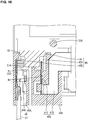
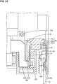
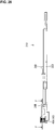
- the fuse connection part 51 is box-shaped, and is provided with an elastic contact piece 51A (see FIGS. 7 , 8 , 16 , 23 , and 29 ).
- the elastic contact piece 51A elastically comes into contact with the connection part 45B of the fuse 45, and is electrically connected thereto.
- the connection of the voltage detection wire 53 is achieved by crimping two pairs of barrel parts 52 of the detection terminal 50.
- the heat transfer member 17 to which the first holding member 30A and the fifth holding member 30E are attached, the heat transfer member 17 to which the second holding member 30B and the fifth holding member 30E are attached, the heat transfer member 17 to which the third holding member 30C and the fifth holding member 30E are attached, and the heat transfer member 17 to which the fourth holding member 30D and the fifth holding member 30E are attached are prepared.
- the terminal connection parts 41A and the extending parts 41B of the fuse connecting busbars 40 are fitted into the recessed parts 38A of the busbar holding parts 38 of the first holding member 30A, the second holding member 30B, the third holding member 30C, and the fourth holding member 30D, and the tuning-fork terminal parts 41C of the fuse connecting busbars 40 are inserted into the terminal insertion parts 43. Furthermore, the external connection busbar 26 is fitted into the recessed part 36A of the connection member holding part 36 of the first holding member 30A.
- the electrical storage elements 12 are respectively placed onto the heat transfer members 17, and the corner parts 15A of the lead terminals 13 are fitted into the electrical storage element holding parts 31 of the holding members 30, so that the lead terminals 13 are overlaid on the fuse connecting busbars 40.
- the lead terminals 13 are also overlaid on the external connection busbar 26.
- the fuse connecting busbars 40 are respectively arranged over the second welding holes 39 each formed in the recessed part 38A of the busbar holding part 38, and the external connection busbar 26 is arranged over the first welding hole 37 formed in the recessed part 36A of the connection member holding part 36.
- the fuse connecting busbar 40 and the lead terminal 13 that are arranged over each second welding hole 39 are joined to each other by ultrasonic welding via the second welding hole 39, and are brought into a connected state.
- the busbars 25 are fitted into and attached to the connection member holding parts 36 on the positive lead terminal 13A side of the first holding member 30A, the second holding member 30B, and the third holding member 30C, and the external connection busbar 26 is fitted into and attached to the connection member holding part 36 on the positive lead terminal 13A side of the fourth holding member 30D.
- the positive lead terminal 13A, and the busbar 25 or the external connection busbar 26 are arranged over the first welding hole 37 formed in the recessed part 36A of each connection member holding part 36.
- the lead terminal 13 and the busbar 25 or the external connection busbar 26 that are arranged over each first welding hole 37 are joined to each other by laser welding via the first welding hole 37.
- the positive lead terminal 13A is joined to the busbar 25, and the negative lead terminal 13B is joined to the external connection busbar 26, and thereby the first electrical storage unit 21A shown in FIG. 4 is obtained.
- the external connection busbar 26 is arranged below the negative lead terminal 13B (see FIG. 5 ).
- the positive lead terminal 13A is joined to the busbar 25, and thereby the second electrical storage unit 21B shown in FIG. 13 is obtained.
- the positive lead terminal 13A is joined to the busbar 25, and thereby the third electrical storage unit 21C shown in FIG. 20 is obtained.
- the positive lead terminal 13A is joined to the external connection busbar 26, and thereby the fourth electrical storage unit 21D shown in FIG. 26 is obtained.
- the fuses 45 are inserted into and mounted to the fuse mounting parts 42, and the detection terminals 50 are inserted into and housed in the terminal housing parts 48.
- the detection terminal 50 is locked to and retained by a lance 48B, and the elastic contact piece 51A of the fuse connection part 51 of the detection terminal 50 elastically comes into contact with the connection part 45B of the fuse 45. Accordingly, the fuses 45 are electrically connected to the detection terminals 50 and the electrical storage elements 12.
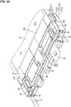
- the stacked body 20 is obtained by stacking the four electrical storage units 21 on one another.
- the second electrical storage unit 21B is overlaid on the first electrical storage unit 21A, the engagement protrusion 34 of the first holding member 30A is engaged with the engagement-receiving part 35 of the second holding member 30B, and the positioning protrusion 33A of the first holding member 30A is fitted into the positioning hole 33B of the second holding member 30B.
- the negative lead terminal 13B of the electrical storage element 12 of the second electrical storage unit 21B is positioned with respect to the busbar 25 joined to the positive lead terminal 13A of the electrical storage element 12 of the first electrical storage unit 21A.
- the negative lead terminal 13B of the electrical storage element 12 of the second electrical storage unit 21B, and the connection part 25A arranged on the upper side of the busbar 25 that is joined to the positive lead terminal 13A of the electrical storage element 12 of the first electrical storage unit 21A are joined to each other by laser welding.
- a stacked body 20A in which the second electrical storage unit 21B is stacked on the first electrical storage unit 21A, as shown in FIG. 32 is obtained.
- the third electrical storage unit 21C is further overlaid on the stacked body 20A, the engagement protrusion 34 of the third holding member 30C is engaged with the engagement-receiving part 35 of the first holding member 30A, and the positioning protrusion 33A of the second holding member 30B is fitted into the positioning hole 33B of the third holding member 30C.
- the negative lead terminal 13B of the electrical storage element 12 attached to the third electrical storage unit 21C is positioned with respect to the busbar 25 joined to the positive lead terminal 13A of the electrical storage element 12 of the second electrical storage unit 21B.
- the negative lead terminal 13B of the electrical storage element 12 of the third electrical storage unit 21C, and the connection part 25A arranged on the upper side of the busbar 25 that is joined to the positive lead terminal 13A of the electrical storage element 12 of the second electrical storage unit 21B are joined to each other by laser welding.
- the third electrical storage unit 21C is stacked on the second electrical storage unit 21B, and a stacked body 20B is obtained.
- the first electrical storage unit 21A, the second electrical storage unit 21B, and the third electrical storage unit 21C are stacked in the stated order from the bottom.
- the fourth electrical storage unit 21D is further overlaid on the stacked body 20B, the engagement protrusion 34 of the second holding member 30B is locked in the engagement-receiving part 35 of the fourth holding member 30D, and the positioning protrusion 33A of the third holding member 30C is fitted into the positioning hole 33B of the fourth holding member 30D.
- the negative lead terminal 13B of the electrical storage element 12 attached to the fourth electrical storage unit 21D is positioned with respect to the busbar 25 joined to the positive lead terminal 13A of the electrical storage element 12 of the third electrical storage unit 21C.
- the negative lead terminal 13B of the electrical storage element 12 of the fourth electrical storage unit 21D, and the connection part 25A arranged on the upper side of the busbar 25 joined to the positive lead terminal 13A of the electrical storage element 12 of the third electrical storage unit 21C are joined to each other by laser welding.
- the fourth electrical storage unit 21D is stacked on the third electrical storage unit 21C, and the stacked body 20 shown in FIG. 33 is obtained.
- the electrical storage module 10 is obtained by placing the stacked body 20 in the case.
- the electrical storage module 10 is provided with the fuses 45 that are electrically connected to the lead terminals 13 of the electrical storage elements 12, and to which the detection terminals 50 are directly connected, and thus there is no need for fuse blocks for connecting the fuses 45 and the detection terminals 50 or members for connecting the fuses 45 and the detection terminals 50. Accordingly, it is possible to realize downsizing and to reduce the number of components as compared with that of a conventional case. As a result, according to the present embodiment, it is possible to downsize the electrical storage module 10 provided with the fuses 45.
- the electrical storage module 10 includes the holding members 30 that have the fuse mounting parts 42 and the terminal housing parts 48, and hold the lead terminals 13 and the fuse connecting busbars 40.
- the fuses 45 are electrically connected to the detection terminals 50 and the electrical storage elements 12, by putting the electrical storage module into a state in which the fuses 45 are mounted on the fuse mounting parts 42, the detection terminals 50 are housed in the terminal housing parts 48, and the fuse connecting busbars 40 and the lead terminals 13 are connected to each other.
- the detection terminals 50 are housed in the terminal housing parts 48 thereof, and the fuse connecting busbars 40 and the lead terminals 13 are connected to each other, it is possible to electrically connect the detection terminals 50 and the electrical storage elements 12 to the fuses 45, thus achieving a connection operation with excellent operability.
- Embodiment 2 according to the technique disclosed in the present description will be described with reference to FIGS. 35 to 60 .
- An electrical storage module 110 according to the present embodiment is mounted in a vehicle that is not shown and is used as an electric power supply.
- the electrical storage module 110 is provided with an electrical storage unit 112 and a circuit unit 113.
- "right”, “front”, and “upper” respectively refer to the X-direction, the Y-direction, and the Z-direction. Furthermore, there may be cases where reference signs are given to only some of a plurality of the same members, and are not given to the remaining members.
- the electrical storage unit 112 as a whole has the shape of a substantially rectangular parallelepiped (see FIG. 35 ).
- the electrical storage unit 112 includes an electrical storage element group 128 in which a plurality of (six in the present embodiment) electrical storage elements 127 are lined up (see FIG. 38 ).
- Each electrical storage element 127 has an electrical storage component (not shown) that is interposed between a pair of rectangular laminate sheets.
- the pair of laminate sheets are joined to each other on their four sides in a state in which the electrical storage component is housed in the inner space therebetween.
- the sides of the pair of laminate sheet are joined to each other by a well-known method, such as thermal fusion bonding, glueing, or the like.
- the upper edge of the electrical storage element 127 is provided with a pair of tabs (an example of the lead terminal) 129 that protrude upward.
- One of the tabs 129 is a positive electrode tab 129A, and the other one is a negative electrode tab 129B.
- the tabs 129 are made of metallic foil. Any metal such as aluminum, an aluminum alloy, copper, or a copper alloy can be used for the metal constituting the tabs 129, as needed.
- the tabs 129 according to the present embodiment are made of copper or a copper alloy.
- the surfaces of the tabs 129 may each be provided with a plated layer made of metal such as tin or nickel.
- Two electrical storage elements 127 are held by being sandwiched between a pair of frames 130 that are made of an insulating synthetic resin in a state in which adjacent tabs 129 have different polarities (see FIG. 36 ).
- the frames 130 have the shape of frames that have, in their central portions, a space in which the electrical storage element 127 is housed.
- the left side edges and the right side edges of the frames 130 are provided with lock parts 131A and lock receiving parts 131B, which are elastically engaged with each other.
- the pair of frames 130 are configured to be assembled as one piece by the lock parts 131A being elastically engaged with the lock receiving parts 131B.
- Two tabs 129 located on the right side of the electrical storage elements 127 are bent at a right angle in the front-rear direction, and are thus connected to each other while overlapping each other.
- the tabs 129 are connected to each other by a well-known method such as laser welding, ultrasonic welding, resistance welding, soldering, or brazing.
- Three pairs of electrical storage elements 127 that are put together by the frames 130 are lined up and are bundled by two binding members 132 that are arranged on the upper and lower sides.
- the binding members 132 are constituted by annular belts that are made of metal or synthetic resin.
- Three pair of electrical storage elements 127 are put together as one piece as a result of the binding members 132 being fitted externally (see FIG. 35 ).
- the six electrical storage elements 127 are lined up so that adjacent tabs 129 have different polarities.
- Two tabs 129 located on the left side of the electrical storage elements 127 are connected to the tabs 129 of the other pairs of electrical storage elements 127 that are lined up so as to be adjacent frontward and rearward to those electrical storage elements 127.
- the tabs 129 are connected to each other by a well-known method such as laser welding, ultrasonic welding, resistance welding, soldering, or brazing.
- An insulating protector 133 (an example of the holding member) that is made of an insulating synthetic resin is attached to the upper portion of the plurality of electrical storage elements 127 bundled by the binding members 132.
- the insulating protector 133 is a substantially rectangular-shaped plate when viewed from above (see FIG. 38 ).
- the insulating protector 133 is provided with a positive electrode busbar 121 that is connected to the positive electrode tab 129A of the electrical storage element 127, and a negative electrode busbar 135 that is connected to the negative electrode tab 129B of the electrical storage element 127 (see FIG. 39 ).
- the positive electrode busbar 121 and the negative electrode busbar 135 are obtained by pressing metal plate materials into predetermined shapes. Any metal such as copper, a copper alloy, aluminum, or an aluminum alloy can be selected for the metal constituting the positive electrode busbar 121 and the negative electrode busbar 135, as needed.
- the positive electrode busbar 121 and the negative electrode busbar 135 are made of copper or a copper alloy.
- the surfaces of the positive electrode busbar 121 and the negative electrode busbar 135 may each be provided with a plated layer made of metal such as tin or nickel.
- the positive electrode busbar 121 is provided with: a positive electrode tab connection part 136 that is connected to the positive electrode tab 129A of the electrical storage element 127, and extends in the left-right direction; a held part 137 that extends downward from the positive electrode tab connection part 136, and is held by the insulating protector 133; and a positive electrode terminal connection part 138 that is provided at a position close to the left end of the held part 137, is bent frontward, and is connected to a first high-current busbar 144.
- the positive electrode tab 129A and the positive electrode tab connection part 136 are connected to each other by a well-known method such as laser welding, ultrasonic welding, soldering, or brazing. In the present embodiment, they are connected to each other by laser welding.
- the held part 137 has a lock receiving part 137A.
- the positive electrode busbar 121 is held by the insulating protector 133 as a result of a lock claw 139 of the insulating protector 133 being elastically engaged with the lock receiving part 137A.
- the positive electrode terminal connection part 138 is provided with a bolt through hole 140 that passes therethrough in the vertical direction. By screwing a bolt 141 into this bolt through hole 140, the positive electrode busbar 121 and the first high-current busbar 144 are electrically connected to each other.
- the negative electrode busbar 135 is provided with: a negative electrode tab connection part 142 that is connected to the negative electrode tab 129B of the electrical storage element 127, and extends in the left-right direction; a held part 143 that extends downward from the negative electrode tab connection part 142, and is held by the insulating protector 133; and an external negative electrode terminal 145 that is bent at a right angle rearward from the outer end, in the left-right direction, of the held part 143.
- the negative electrode tab 129B and the negative electrode tab connection part 142 are connected to each other by a well-known method such as laser welding, ultrasonic welding, soldering, or brazing. In the present embodiment, they are connected to each other by laser welding.
- the held part 143 has a lock receiving part 143A.
- the negative electrode busbar 135 is held by the insulating protector 133 as a result of a lock claw 146 of the insulating protector 133 being elastically engaged with the lock receiving part 143A.
- the external negative electrode terminal 145 is bent upward in the shape of a crank when viewed in the left-right direction.
- the end, in the front-rear direction, of the external negative electrode terminal 145 is provided with a bolt through hole 147 that passes therethrough in the vertical direction.
- the upper surface of the insulating protector 133 is provided with a plurality of openings 149 that pass therethrough in the vertical direction.
- the tabs 129 are inserted through the openings 149 from below.
- the upper surface of the insulating protector 133 is provided with two lines in which openings 149 are lined up at a distance in the front-rear direction are formed in the left-right direction.
- the positive electrode tabs 129A and the negative electrode tabs 129B of the electrical storage elements 127 are overlapped and welded to each other in the state of being passed through the openings 149.
- a fuse connecting busbar 150 is provided at a position in each opening 149 that is close to the central portion thereof in the left-right direction.
- the fuse connecting busbars 150 are obtained by pressing metal plate members into a predetermined shape. Any metal such as copper, a copper alloy, aluminum, or an aluminum alloy can be selected for the metal constituting the fuse connecting busbars 150, as needed.
- the surfaces of the fuse connecting busbars 150 may each be provided with a plated layer made of metal such as tin or nickel.
- Each fuse connecting busbar 150 is provided with: a tab connection part 151 that is connected to a positive electrode tab 129A or a negative electrode tab 129B that is arranged in the opening 149; an extended part 152 that extends downward from the tab connection part 151 and extends in the left-right direction; and a fuse terminal connection part 153 that extends downward from the extended part 152.
- the lower end of the fuse terminal connection part 153 is fork-shaped and is divided into two portions, which are configured to sandwich and hold a fuse terminal 155A of a low-current fuse 154 (an example of the fuse) that will be described later.
- the insulating protector 133 is provided with fuse mounting parts 156 to which the low-current fuses 154 are mounted and that are open downward (see FIG. 42 ).
- the above-described fuse terminal connection parts 153 of the fuse connecting busbars 150 protrude into the fuse mounting parts 156 from above (see FIG. 59 ).
- the low-current fuses 154 are mounted on the fuse mounting parts 156 from below. Each low-current fuse 154 has fuse terminals 155A and 155B on both ends in the left-right direction.
- fuse terminal connection parts 158 of voltage detection terminals (an example of the detection terminal) 157 protrude into the fuse mounting part 156 from above. Also the lower end of the fuse terminal connection part 158 of each voltage detection terminals 157 is fork-shaped and is divided into two portions, which are configured to sandwich and hold the fuse terminal 155B of the low-current fuse 154.
- the voltage detection terminals 157 are obtained by pressing metal plate members into a predetermined shape. Any metal such as copper, a copper alloy, aluminum, or an aluminum alloy can be selected for the metal constituting the voltage detection terminals 157, as needed.
- the surfaces of the voltage detection terminals 157 may each be provided with a plated layer made of metal such as tin or nickel.
- the voltage detection terminals 157 are formed so as to extend in the vertical direction. As described above, the lower ends of the voltage detection terminals 157 serve as the fuse terminal connection parts 158. On the other hand, the upper ends of the voltage detection terminals 157 are tab-shaped.
- the upper surface of the insulating protector 133 is provided with, in the central portion in the left-right direction, a plurality of (seven in the present embodiment) standby connectors 159 (an example of the terminal housing part) that are open upward (see FIG. 41 ).
- the standby connectors 159 are formed while being lined up in the zigzag shape in the front-rear direction. In other words, a line in which three standby connectors 159 are lined up in the front-rear direction, and a line in which four standby connectors 159 are lined up in the front-rear direction are arranged at a distance in the left-right direction, and the standby connectors 159 in the respective lines are arranged at positions that are shifted from each other in the left-right direction.
- the upper ends of the voltage detection terminals 157 are arranged so as to protrude upward into the standby connectors 159.
- Relay terminals 160 are fitted to the upper ends of the voltage detection terminals 157 from above (see FIG. 43 ).
- the relay terminals 160 are obtained by pressing metal plate materials into a predetermined shape and then bending the pressed metal plate materials. Any metal such as copper, a copper alloy, aluminum, or an aluminum alloy can be selected for the metal constituting the relay terminals 160, as needed. A plated layer made of metal such as tin or nickel may be formed on the surface of the relay terminals 160.
- the relay terminals 160 substantially have the shape of a box that opens in the vertical direction.
- An elastic piece 161 is arranged in each relay terminal 160. By bringing the elastic pieces 161 into elastic contact with the upper ends of the voltage detection terminals 157, the relay terminals 160 and the voltage detection terminals 157 are electrically connected to each other.
- the circuit unit 113 as a whole is substantially L-shaped when viewed in the left-right direction (see FIG. 54 ).
- the circuit unit 113 is attached to the upper surface of the electrical storage unit 112 and to a side surface that is contiguous downward from an edge of the upper surface.
- the circuit unit 113 is provided with: high-current components 183 through which relatively high current flows; and low-current components 184 through which a current lower than the current flowing through the high-current components 183 flows.
- the electrical storage unit 112 and the circuit unit 113 are assembled, by elastically engaging the lock parts 162A formed on the electrical storage unit 112 with the lock receiving parts 162B formed on the circuit unit 113 at the positions that correspond to the lock parts 162A (see FIGS. 57 and 60 ).
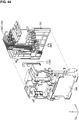
- the circuit unit 113 includes: a lower case 163; and an upper case 164 that is attached to the upper side of the lower case 163 (see FIG. 44 ).
- the lower case 163 and the upper case 164 are made of an insulating synthetic resin.
- the lower case 163 and the upper case 164 are assembled by elastically engaging lock parts 165A formed on the lower case 163 with lock receiving parts 165B formed on the upper case 164 at the positions that correspond to the lock parts 165A (see FIGS. 53 and 55 ).
- the lower case 163 is provided with: a side wall that extends in the vertical direction; and an upper wall that is bent at substantially a right angle from the upper end of the side wall in the front-rear direction (see FIG. 45 ).
- the lower surface of the upper wall of the lower case 163 is provided with circuit unit-side connectors 165 at positions that are in the vicinity of the central portion in the left-right direction and correspond to the standby connectors 159 of the insulating protector 133 (see FIG. 46 ).
- the circuit unit-side connectors 165 have the shape of a square tube that opens downward. Ends of first low-current busbars 167 (an example of the busbars and an example of the low-current components 184) that will be described later protrude into the circuit unit-side connectors 165 from above.
- the ends of the first low-current busbars 167 are fitted to the relay terminals 160 of the standby connectors 159 from above (see FIG. 59 ).
- guide parts 168 that protrude upward are formed in the vicinity of the standby connectors 159.
- two guide parts 168 are formed.
- One of the two guide parts 168 is formed at the position on the left side of the second standby connector 159 from the rear end.
- the other one of the guide parts 168 is formed on the left side of the second standby connector 159 from the front end.
- the lower surface of the upper wall of the lower case 163 is provided with, at the positions that correspond to the guide parts 168, guide-target parts 169 that are recessed upward and into which the guide parts 168 are inserted.
- the upper surface of the upper wall of the lower case 163 and the surface of the side wall of the lower case 163 that faces away from the electrical storage unit 112 are provided with: a plurality of (seven in the present embodiment) first low-current busbars 167 (an example of the low-current components 184); a plurality of (four in the present embodiment) second low-current busbars 170 (an example of the low-current components 184); and a plurality of (two in the present embodiment) third low-current busbars 171 (an example of the low-current components 184) (see FIG. 45 ).
- the first low-current busbars 167, the second low-current busbars 170, and the third low-current busbars 171 are arranged between the lower case 163 and the upper case 164.
- the first low-current busbars 167, the second low-current busbars 170, and the third low-current busbars 171 are obtained by pressing metal plate members into predetermined shapes. Any metal such as copper, a copper alloy, aluminum, or an aluminum alloy can be selected for the metal constituting the first low-current busbars 167, the second low-current busbars 170, and the third low-current busbars 171, as needed.
- the surfaces of the first low-current busbars 167, the second low-current busbars 170, and the third low-current busbars 171 may each be provided with a plated layer made of metal such as tin or nickel.
- the first low-current busbars 167 are arranged on the upper surface of the upper wall of the lower case 163 and the rear surface of the side wall of the lower case 163 (see FIG. 45 ).
- the ends of the portions of the first low-current busbars 167 that are provided on the upper surface of the upper wall of the lower case 163 are located inside of the above-described circuit unit-side connectors 165 while being bent downward, and are connected to the relay terminals 160.
- the lower ends of the first low-current busbars 167 are bent rearward, and thus are connected to a BSU 173 (Battery Sensing Unit) that will be descried later.
- the BSU 173 is configured to calculate a voltage value of each electrical storage element 127 based on a minute electric current that flows to the BSU 173 via the first low-current busbar 167.
- the second low-current busbars 170 are arranged on the rear surface of the side wall of the lower case 163 (see FIG. 45 ).
- the lower ends of the second low-current busbars 170 are bent rearward, and are connected to the BSU 173.
- the upper ends of the second low-current busbars 170 are bent rearward, and are connected to a current sensor 174 that will be described later.
- the BSU 173 is configured to calculate values of currents that flow through the first high-current busbar 144 (an example of the high-current components 183) that will be described later, based on current signals that are transferred from the current sensor 174 to the BSU 173 via the second low-current busbars 170.
- the third low-current busbars 171 are arranged on the rear surface of the lower case 163 (see FIG. 45 ).
- the lower ends of the third low-current busbars 171 are bent rearward, and are connected to the BSU 173.
- the upper ends of the third low-current busbars 171 are bent rearward, and are connected to a relay 175 (an example of the high-current components 183) that will be described later.
- the relay 175 is configured to be energized or deenergized in response to a switching signal that is transferred from the BSU 173 to the relay 175 via the third low-current busbars 171.
- the upper case 164 is provided with: a side wall that extend in the vertical direction; and an upper wall that is bent at substantially a right angle from the upper end of the side wall in the front-rear direction (see FIG. 47 ).
- the first high-current busbar 144 is provided on the upper surface of the upper wall of the upper case 164 and the rear surface of the side wall of the upper case 164 (see FIG. 35 ).
- the first high-current busbar 144 is obtained by pressing a metal plate member into a predetermined shape. Any metal such as copper, a copper alloy, aluminum, or an aluminum alloy can be selected for the metal constituting the first high-current busbar 144, as needed.
- the surface of the first high-current busbar 144 may be provided with a plated layer made of metal such as tin or nickel.
- the end of the first high-current busbar 144 that is arranged on the upper surface of the upper wall of the upper case 164 is fixed to the positive electrode terminal connection part 138 of the positive electrode busbar 121 with the bolt 141.
- the portion of the first high-current busbar 144 that is arranged on the rear surface of the side wall of the upper case 164 penetrates the current sensor 174 (see FIG. 49 ).
- the current sensor 174 detects a current flowing through the first high-current busbar 144 with a well-known method.
- the current sensor 174 transmits a current signal to the BSU 173 via the second low-current busbars 170.
- the current sensor 174 may be configured to transmit a current signal to an ECU via a connector and an external circuit-side connector.
- the lower end of the first high-current busbar 144 is connected to a lead terminal 178A of a high-current fuse 177 (an example of the high-current component 183) with the bolt 179.
- the high-current fuse 177 has a pair of lead terminals 178A and 178B.
- the lead terminal 178A which is one of the pair of lead terminals, is connected to the lower end of the above-described first high-current busbar 144.
- the other lead terminal 178B is connected to one lead terminal 180A of the relay 175 with a bolt 181.
- the relay 175 is turned on and off in response to a signal transmitted from the BSU 173 via the third low-current busbars 171.
- the BSU 173 receives a current signal from the current sensor 174 via the second low-current busbars 170, and turns the relay 175 off when the current value calculated based on this current signal is larger than a predetermined threshold.
- Another lead terminal 180B of the relay 175 is connected to a second high-current busbar 123 (an example of the high-current components 183) with a bolt 182.
- the second high-current busbar 123 is arranged on the rear surface of the side wall of the upper case 164 and the upper surface of the upper wall of the upper case 164.
- the end of the second high-current busbar 123 that is arranged on the upper surface of the upper wall of the upper case 164 serves as an external positive electrode terminal 148.
- the voltage detection terminals 157 are connected to the first low-current busbars 167 via the relay terminals 160. Accordingly, it is possible to downsize the routing space as compared with the case where electric wires are connected to the voltage detection terminals 157. Furthermore, since it is possible to process the plurality of first low-current busbars 167 into predetermined shapes in the same process, the manufacturing process can be simplified.
- the circuit unit 113 is provided with the insulating lower case 163, and the insulating upper case 164, which is attached to the lower case 163, and the first low-current busbars 167, the second low-current busbars 170, and the third low-current busbars 171 are arranged between the lower case 163 and the upper case 164. Accordingly, the first low-current busbars 167, the second low-current busbars 170, and the third low-current busbars 171 are reliably insulated by the lower case 163 and the upper case 164.
- the electrical storage unit 112 is provided with the guide parts 168 by which relative positioning of the electrical storage unit 112 and the circuit unit 113 is performed. Accordingly, it is possible to improve the work efficiency when the electrical storage unit 112 and the circuit unit 113 are assembled with each other.
- the electrical storage unit 112 includes the standby connectors 159
- the circuit unit 113 includes the circuit unit-side connectors 166, which are fitted to the standby connectors 159.
- the guide parts 168 are formed in the vicinity of the standby connectors 159. Accordingly, it is possible to prevent the standby connectors 159 and the circuit unit-side connectors 166 from being erroneously fitted to each other.
Landscapes
- Engineering & Computer Science (AREA)
- Power Engineering (AREA)
- Chemical & Material Sciences (AREA)
- Chemical Kinetics & Catalysis (AREA)
- Electrochemistry (AREA)
- General Chemical & Material Sciences (AREA)
- Microelectronics & Electronic Packaging (AREA)
- Manufacturing & Machinery (AREA)
- Connection Of Batteries Or Terminals (AREA)
- Electric Double-Layer Capacitors Or The Like (AREA)
- Battery Mounting, Suspending (AREA)
Abstract
Description
- The present invention relates to an electrical storage module.
- In general, battery modules mounted on, for example, electric cars or hybrid vehicles are constituted by connecting multiple electric cells in series or parallel with each other via busbars (see
Patent Document 1, for example). Such a battery module includes detection terminals for detecting a state of the electric cells, and detection electric wires connected to the detection terminals. - Patent Document 1:
JP 2013-106400A - In the battery module of
Patent Document 1, fuses are connected to the detection electric wires, and if the detection electric wires are shorted, the fuses will be melted down to prevent the electric cells from being shorted. Because this battery module includes a resin protector in which the detection electric wires are housed, and a fuse block that is separate from the resin protector, there is a limit in downsizing. - An object of the present invention is to downsize an electrical storage module provided with fuses.
- According to the present invention, an electrical storage module includes: an electrical storage element group in which a plurality of electrical storage elements are stacked on one another, each electrical storage element having lead terminals that protrude from a side edge of the electrical storage element; and fuses that are electrically connected to the lead terminals, wherein detection terminals for detecting a state of the electrical storage elements are directly connected to the fuses.
- According to the present invention, the electrical storage module includes the fuses that are electrically connected to the lead terminals of the electrical storage elements, and the detection terminals are directly connected to the fuses. Thus, according to the present invention, there is no need for fuse blocks for connecting the fuses and the detection terminals, or members for connecting the fuses and the detection terminals. Accordingly, it is possible to realize downsizing and to reduce the number of the components as compared with that of a conventional case.
- As a result, according to the present invention, it is possible to downsize the electrical storage module provided with the fuses.
- The present invention may have a configuration in which holding members that hold the lead terminals and fuse connecting busbars that electrically connect the fuses and the lead terminals, each holding member being provided with a fuse mounting part on which a fuse is mounted, and a terminal housing part in which a detection terminal is housed, wherein the fuses are electrically connected to the detection terminals and the electrical storage elements, by putting the electrical storage module into a state in which the fuses are mounted on the fuse mounting parts, the detection terminals are housed in the terminal housing parts, and the fuse connecting busbars and the lead terminals are connected to each other.
- With such a configuration, only by obtaining the state in which the fuses are mounted on the fuse mounting parts of the holding members, the detection terminals are housed in the terminal housing parts thereof, and the fuse connecting busbars and the lead terminals are connected to each other, it is possible to electrically connect the detection terminals and the electrical storage elements to the fuses, thus achieving the excellent operability of the connecting operation.
- The detection terminals may be connected to busbars via relay terminals.
- With such a configuration, it is possible to downsize the routing space as compared with the case where electric wires are connected to the detection terminals. Furthermore, since it is possible to process the plurality of busbars into predeteriend shapes in the same process, the manufacturing process can be simplified.
- According to the present invention, it is possible to downsize an electrical storage module provided with fuses.
-
-
FIG. 1 is a perspective view illustrating an electrical storage module according toEmbodiment 1. -
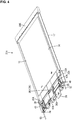
FIG. 2 is a plan view illustrating the electrical storage module. -
FIG. 3 is a cross-sectional view taken along a line A-A ofFIG. 2 . -
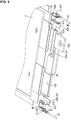
FIG. 4 is a perspective view illustrating a first electrical storage unit (electrical storage unit in the lowermost stage). -
FIG. 5 is a partial perspective view of the first electrical storage unit (without a holding member). -
FIG. 6 is a front view of the first electrical storage unit. -
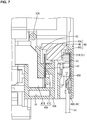
FIG. 7 is a cross-sectional view taken along a line B-B ofFIG. 6 . -
FIG. 8 is a cross-sectional view taken along a line C-CFIG. 6 . -
FIG. 9 is an exploded perspective view of the first electrical storage unit. -
FIG. 10 is a perspective view illustrating a first fuse connecting busbar. -
FIG. 11 is a perspective view illustrating a second fuse connecting busbar. -
FIG. 12 is a perspective view illustrating a first holding member. -
FIG. 13 is a perspective view illustrating a second electrical storage unit (electrical storage unit in the second stage from the bottom). -
FIG. 14 is a partial perspective view of the second electrical storage unit (without a holding member). -
FIG. 15 is a front view of the second electrical storage unit. -
FIG. 16 is a cross-sectional view taken along a line D-D ofFIG. 15 . -
FIG. 17 is an exploded perspective view of the second electrical storage unit. -
FIG. 18 is a perspective view illustrating a third fuse connecting busbar. -
FIG. 19 is a perspective view illustrating a second holding member. -
FIG. 20 is a perspective view illustrating a third electrical storage unit (electrical storage unit in the third stage from the bottom). -
FIG. 21 is a partial perspective view of the third electrical storage unit (without a holding member). -
FIG. 22 is a front view of the third electrical storage unit. -
FIG. 23 is a cross-sectional view taken along a line E-E ofFIG. 22 . -
FIG. 24 is an exploded perspective view of the third electrical storage unit. -
FIG. 25 is a perspective view illustrating a third holding member. -
FIG. 26 is a perspective view illustrating a fourth electrical storage unit (electrical storage unit at the uppermost stage). -
FIG. 27 is a partial perspective view of the fourth electrical storage unit (without a holding member). -
FIG. 28 is a front view of the fourth electrical storage unit. -
FIG. 29 is a cross-sectional view taken along a line F-F ofFIG. 28 . -
FIG. 30 is an exploded perspective view of the fourth electrical storage unit. -
FIG. 31 is a perspective view illustrating a fourth holding member. -
FIG. 32 is a perspective view illustrating a state in which the first electrical storage unit and the second electrical storage unit are stacked on each other. -
FIG. 33 is a perspective view illustrating a state in which the first electrical storage unit, the second electrical storage unit, and the third electrical storage unit are stacked on one another. -
FIG. 34 is a perspective view illustrating a state in which four electrical storage units are stacked on one another. -
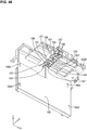
FIG. 35 is an exploded perspective view illustrating an electrical storage module according to Embodiment 2. -
FIG. 36 is an exploded perspective view illustrating frame parts and electrical storage elements. -
FIG. 37 is a perspective view illustrating the electrical storage elements sandwiched by the frame parts. -
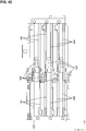
FIG. 38 is a plan view illustrating the electrical storage units. -
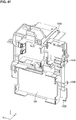
FIG. 39 is an exploded perspective view illustrating an insulating protector and the electric connection structure of the electrical storage units. -
FIG. 40 is a perspective view illustrating the insulating protector. -
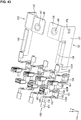
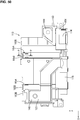
FIG. 41 is a plan view illustrating the insulating protector. -
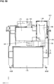
FIG. 42 is a bottom view illustrating the insulating protector. -
FIG. 43 is a perspective view illustrating the electric connection structure of the electrical storage units. -
FIG. 44 is an exploded perspective view illustrating a circuit unit. -
FIG. 45 is a perspective view illustrating a lower case and low-current components. -
FIG. 46 is a perspective view illustrating the lower case viewed in a direction different from the direction ofFIG. 45 . -
FIG. 47 is a perspective view illustrating an upper case. -
FIG. 48 is a perspective view illustrating the electric connection structure between the electrical storage units and the circuit unit. -
FIG. 49 is an exploded perspective view illustrating the upper case and high-current components. -
FIG. 50 is a plan view illustrating the circuit unit. -
FIG. 51 is a cross-sectional view taken along a line P-P ofFIG. 50 . -
FIG. 52 is a rear view illustrating the circuit unit. -
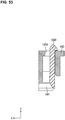
FIG. 53 is a cross-sectional view taken along a line Q-Q ofFIG. 52 . -
FIG. 54 is a side view illustrating the circuit unit. -
FIG. 55 is a front view illustrating the circuit unit. -
FIG. 56 is a perspective view illustrating a state in which the electrical storage units and the circuit unit are assembled. -
FIG. 57 is a rear view illustrating the state in which the electrical storage units and the circuit unit are assembled. -
FIG. 58 is a plan view illustrating the state in which the electrical storage units and the circuit unit are assembled. -
FIG. 59 is a cross-sectional view taken along a line R-R ofFIG. 58 . -
FIG. 60 is a cross-sectional view taken along a line S-S ofFIG. 58 . - An
electrical storage module 10 according toEmbodiment 1 will be described with reference toFIGS. 1 to 34 . In the drawings, there may be cases where reference signs are given to only one of a plurality of the same members and are not given to the remaining members. In the following description, "front" and "rear" respectively refer to the left side and right side ofFIG. 2 . - The
electrical storage module 10 of the present embodiment includes: an electricalstorage element group 11 in which a plurality of (four in the present embodiment)electrical storage elements 12 are stacked on one another, each electrical storage element havinglead terminals 13 that protrude from a side edge of the electrical storage element; and fuses 45 that are electrically connected to thelead terminals 13. In the present embodiment, theelectrical storage module 10 further includes: holdingmembers 30 that are respectively attached to the side edges at which thelead terminals 13 are provided, and hold theelectrical storage elements 12; andfuse connecting busbars 40 that are connected to thelead terminals 13 and to thefuses 45. - In the present embodiment, any
electrical storage elements 12 such as secondary batteries, capacitors, and condensers may be used as needed as theelectrical storage elements 12 constituting the electricalstorage element group 11. According to the present embodiment, secondary batteries are used as theelectrical storage elements 12. - As shown in
FIG. 1 , theelectrical storage module 10 according to the present embodiment includes: astacked body 20 that is made of a stack of four electrical storage units 21 each obtained by placing theelectrical storage element 12 on aheat transfer member 17 to which the holdingmembers 30 are attached; and a case that is not shown. - The four electrical storage units 21 that constitute the
stacked body 20 are a firstelectrical storage unit 21A, a secondelectrical storage unit 21B, a thirdelectrical storage unit 21C, and a fourthelectrical storage unit 21D in the stated order from the bottom. Each of the electrical storage units 21 includes the holdingmembers 30 attached to both ends in its longitudinal direction, theheat transfer member 17, and theelectrical storage element 12. - The
heat transfer member 17 is a plate-shaped member made of a heat conductive material. In the present embodiment, aluminum or an aluminum alloy, which has excellent heat conductivity, is used as the heat conductive material. The holdingmembers 30 made of an insulating resin material are attached to both ends in the longitudinal direction of theheat transfer member 17, and theelectrical storage element 12 is placed on the upper surface of theheat transfer member 17. - As shown in
FIG. 2 , theelectrical storage element 12 is substantially rectangular when viewed from above. Theelectrical storage element 12 includes: acontainer 14 obtained by welding side edges of a pair of substantially rectangular laminate films; an electrical storage component that is not shown and is contained in the inside of thecontainer 14; and thelead terminals 13 that are connected to the electrical storage component inside thecontainer 14 and are drawn from a side edge of thecontainer 14 to the outside. In the present embodiment, thelead terminals 13 of positive and negative polarities are drawn from one side edge (front side edge) of thecontainer 14. - On the side edge of the
electrical storage element 12,corner parts 15A at protruding ends of thelead terminals 13 are fitted to electrical storageelement holding parts 31 of the holdingmember 30, so that displacement of theelectrical storage element 12 is restricted. - In the present embodiment, as shown in
FIG. 3 ,busbars 25 are connected by welding to the ends of thelead terminals 13 that are adjacent to each other in a stacking direction (vertical direction inFIG. 3 ), and theelectrical storage elements 12 are electrically connected to each other via thebusbars 25. Furthermore,external connection busbars 26 for connection to external devices are connected to thelead terminal 13 of theelectrical storage element 12 of the firstelectrical storage unit 21A (electrical storage unit 21 in the lowermost stage), and to thelead terminal 13 of theelectrical storage element 12 of the fourthelectrical storage unit 21D (electrical storage unit 21 in the uppermost stage). - In the present embodiment, the
electrical storage elements 12 that are overlaid in the stacking direction are connected in series to each other by connecting thelead terminals 13 having opposite polarities to each other via thebusbars 25. Thelead terminals 13 include a positive lead terminal 13A and anegative lead terminal 13B. - Metal
fuse connecting busbars 40 to connect thefuses 45 and thelead terminals 13 are connected by welding to thelead terminals 13. Thelead terminals 13 are made of aluminum or an aluminum alloy. - In the first
electrical storage unit 21A, the negative lead terminal 13B of theelectrical storage element 12 is overlaid directly on and joined by welding to a firstfuse connecting busbar 40A and theexternal connection busbar 26, which are arranged side by side on the holdingmember 30. Furthermore, in the firstelectrical storage unit 21A, the positive lead terminal 13A of theelectrical storage element 12 is overlaid directly on and joined by welding to a secondfuse connecting busbar 40B arranged on the holdingmember 30, and is joined by welding to thebusbar 25 overlaid on this positive lead terminal 13A. - In the second
electrical storage unit 21B (electrical storage unit 21 in the second stage from the bottom) and the thirdelectrical storage unit 21C (electrical storage unit 21 in the third stage from the bottom), the positive lead terminal 13A of theelectrical storage element 12 is overlaid directly on and joined by welding to thefuse connecting busbar 40 arranged on the holdingmember 30, and is joined by welding to thebusbar 25 overlaid on this positivelead terminal 13A (seeFIGS. 17 and24 ). - In the fourth
electrical storage unit 21D, the positive lead terminal 13A of theelectrical storage element 12 is overlaid directly on and joined by welding to a thirdfuse connecting busbar 40C arranged sideways on the holdingmember 30, and is joined by welding to theexternal connection busbar 26 overlaid on this positivelead terminal 13A (seeFIG. 30 ). - Examples of the welding method include a laser welding method, an ultrasonic welding method, and the like.
- A holding
member 30 of each electrical storage unit 21 is provided with electrical storageelement holding parts 31 that are recessed and into which thecorner parts 15A of thelead terminals 13 of theelectrical storage element 12 are fitted. This electrical storageelement holding parts 31 restrict the displacement of the lead terminals 13 (electrical storage element 12). - In the present embodiment, five types of holding
members 30 are used. Of the two holdingmembers 30 constituting (i.e. part of) the firstelectrical storage unit 21A, the holdingmember 30 arranged on the front side is a first holdingmember 30A (seeFIGS. 4 and12 ), and the holdingmember 30 arranged on the rear side is a fifth holdingmember 30E (seeFIG. 4 ). - Of the two holding
members 30 constituting the secondelectrical storage unit 21B, the holdingmember 30 arranged on the front side is asecond holding member 30B (seeFIGS. 13 and19 ), and the holdingmember 30 arranged on the rear side is the fifth holdingmember 30E (seeFIG. 13 ). - Of the two holding
members 30 constituting the thirdelectrical storage unit 21C, the holdingmember 30 arranged on the front side is athird holding member 30C (seeFIGS. 20 and25 ), and the holdingmember 30 arranged on the rear side is the fifth holdingmember 30E (seeFIG. 20 ). - Of the two holding
members 30 constituting the fourthelectrical storage unit 21D, the holdingmember 30 arranged on the front side is afourth holding member 30D (seeFIGS. 26 and31 ), the holdingmember 30 arranged on the rear side is the fifth holdingmember 30E (seeFIG. 26 ). - Each of the holding
members fuse mounting part 42 on which thefuse 45 is mounted, and aterminal housing part 48 in which thedetection terminal 50 is housed, and holds thelead terminals 13 and thefuse connecting busbar 40 that electrically connects thefuse 45 and thelead terminal 13. - Each holding
member 30 is provided with a heat transfermember mounting part 32 into which theheat transfer member 17 is inserted and attached. - The
first holding member 30A has, at a position close to the right side ofFIG. 12 , apositioning protrusion 33A for positioning the second holdingmember 30B. Thesecond holding member 30B has, at the position close to the right side ofFIG. 19 , apositioning hole 33B for receiving thepositioning protrusion 33A of the first holdingmember 30A, and has, at the position close to the left side of the figure, apositioning protrusion 33A for positioning the third holdingmember 30C. - The
third holding member 30C has, at the position close to the left side ofFIG. 25 , apositioning hole 33B for receiving thepositioning protrusion 33A of the second holdingmember 30B, and has, at the position close to the right side of the figure, apositioning protrusion 33A for positioning the fourth holdingmember 30D. - The
fourth holding member 30D has, at the position close to the right side ofFIG. 31 , apositioning hole 33B for receiving thepositioning protrusion 33A of the third holdingmember 30C. - The
first holding member 30A has anengagement protrusion 34 that protrudes upward and engages with the second holdingmember 30B, and an engagement-receivingpart 35 that receives and engages with theengagement protrusion 34 of the third holdingmember 30C. Thesecond holding member 30B has an engagement-receivingpart 35 that receives and engages with theengagement protrusion 34 of the first holdingmember 30A, and anengagement protrusion 34 that protrudes upward and engages with the fourth holdingmember 30D. - The
third holding member 30C has anengagement protrusion 34 that protrudes downward and engages with the engagement-receivingpart 35 of the first holdingmember 30A. Thefourth holding member 30D has an engagement-receivingpart 35 that receives and engages with theengagement protrusion 34 of the second holdingmember 30B. - The
first holding member 30A, the second holdingmember 30B, the third holdingmember 30C, and the fourth holdingmember 30D are each provided with a connectionmember holding part 36 that holds thebusbar 25 or theexternal connection busbar 26, and thelead terminal 13 in a state in which they are overlaid on each other. The connectionmember holding part 36 is provided with a recessedpart 36A into which thebusbar 25 or theexternal connection busbar 26 can be fitted, and a retainingprotrusion 36B that retains thebusbar 25 or theexternal connection busbar 26 that is fitted into the recessedpart 36A. - The
first holding member 30A, the second holdingmember 30B, the third holdingmember 30C, and the fourth holdingmember 30D are each provided with afirst welding hole 37 for use in welding and connecting thelead terminal 13 of theelectrical storage element 12 to the connection member (thebusbar 25 or the external connection busbar 26) to be connected to thelead terminal 13 of the electrical storage element 12 (seeFIGS. 12 ,19 ,25 , and31 ). - The
busbars 25 are made of aluminum or an aluminum alloy, and are arranged overlapping thelead terminals 13. As shown inFIG. 3 , thebusbars 25 have a U-shaped cross section so thatconnection parts 25A connected to thelead terminals 13 are arranged at a distance in the vertical direction. - The
external connection busbars 26 are made of aluminum or an aluminum alloy, and are arranged overlapping thelead terminals 13. An end of each of theexternal connection busbars 26 protrudes frontward, and is provided with aconnection hole 26A through which an external connection terminal (not shown) is to be connected thereto. - The
first holding member 30A, the second holdingmember 30B, the third holdingmember 30C, and the fourth holdingmember 30D are each provided with abusbar holding part 38 that holds thefuse connecting busbar 40, afuse mounting part 42 on which thefuse 45 is mounted, and aterminal housing part 48 for housing thedetection terminal 50 that is connected to thefuse 45. - The
fuse connecting busbar 40 held by thebusbar holding part 38 has aterminal connection part 41A that is overlaid on and connected to thelead terminal 13, an extendingpart 41B that extends laterally from theterminal connection part 41A, and a tuning-fork terminal part 41C that is folded upward in the vertical direction relative to the extendingpart 41B, and is formed by being divided at an end into two portions. Thefuse connecting busbar 40 is made of, for example, a metal material such as copper, a copper alloy, aluminum, or an aluminum alloy. Thefuse 45 is interposed between the divided portions of the tuning-fork terminal part 41C, and is electrically connected to the tuning-fork terminal part 41C. - Three types of the
fuse connecting busbars 40, specifically, the firstfuse connecting busbar 40A shown inFIG. 10 , the secondfuse connecting busbar 40B shown inFIG. 11 , and the thirdfuse connecting busbar 40C shown inFIG. 18 , are used. - The first
fuse connecting busbar 40A is arranged under the negative lead terminal 13B of the firstelectrical storage unit 21A, and has a shape in which astep part 41D is formed between theterminal connection part 41A and the extendingpart 41B. - The second
fuse connecting busbars 40B are arranged under the positive lead terminal 13A of the firstelectrical storage unit 21A, and the positive lead terminal 13A of the thirdelectrical storage unit 21C. - The third
fuse connecting busbars 40C are arranged under the positive lead terminal 13A of the secondelectrical storage unit 21B, and the positive lead terminal 13A of the fourthelectrical storage unit 21D. - The second
fuse connecting busbar 40B and the thirdfuse connecting busbar 40C are symmetric, and do not have thestep part 41D. - The
busbar holding part 38 has a recessedpart 38A into which theterminal connection part 41A and the extendingpart 41B of thefuse connecting busbar 40 are fitted. Thefirst holding member 30A, the second holdingmember 30B, the third holdingmember 30C, and the fourth holdingmember 30D each have asecond welding hole 39 for use in welding thelead terminal 13 to the fuse connecting busbar 40 (seeFIGS. 12 ,19 ,25 , and31 ). - The
fuse mounting part 42 and theterminal housing part 48 are provided as one piece that is box-shaped as shown inFIGS. 12 ,19 ,25 , and31 . Thefuse mounting part 42 opens so that thefuse 45 can be inserted thereinto from the rear side. The upper wall of thefuse mounting part 42 is provided with aterminal insertion part 43 into which the tuning-fork terminal part 41C of thefuse connecting busbar 40 is inserted. - The
detection terminal 50 for detecting a state of the electrical storage element is directly connected to eachfuse 45. Specifically, thefuse 45 includes aconnection part 45A that is interposed between the divided portions of the tuning-fork terminal part 41C of thefuse connecting busbar 40 and is electrically connected to the tuning-fork terminal part 41C, aconnection part 45B that is directly connected to thedetection terminal 50, and an insulatingpart 46 that is made of an insulating resin and is provided so as to join the twoconnection parts FIGS. 5 ,14 ,21 , and27 ). The twoconnection parts part 46. Theconnection parts fuse 45, thefuse 45 is melted down, interrupting the overcurrent. - The
terminal housing part 48 that houses thedetection terminal 50 is anopening 48A that opens on the front side, and in which afuse connection part 51 of thedetection terminal 50 is arranged. - The
detection terminal 50 is obtained by pressing a metal plate material into a predetermined shape. An electric wire for voltage detection (voltage detection wire 53) is connected to the front end of thedetection terminal 50, and thefuse connection part 51 connected to theconnection part 45B of thefuse 45 is provided at the rear end of thedetection terminal 50. Thefuse connection part 51 is box-shaped, and is provided with anelastic contact piece 51A (seeFIGS. 7 ,8 ,16 ,23 , and29 ). Theelastic contact piece 51A elastically comes into contact with theconnection part 45B of thefuse 45, and is electrically connected thereto. The connection of thevoltage detection wire 53 is achieved by crimping two pairs ofbarrel parts 52 of thedetection terminal 50. - The
heat transfer member 17 to which the first holdingmember 30A and the fifth holdingmember 30E are attached, theheat transfer member 17 to which the second holdingmember 30B and the fifth holdingmember 30E are attached, theheat transfer member 17 to which the third holdingmember 30C and the fifth holdingmember 30E are attached, and theheat transfer member 17 to which the fourth holdingmember 30D and the fifth holdingmember 30E are attached are prepared. - The
terminal connection parts 41A and the extendingparts 41B of thefuse connecting busbars 40 are fitted into the recessedparts 38A of thebusbar holding parts 38 of the first holdingmember 30A, the second holdingmember 30B, the third holdingmember 30C, and the fourth holdingmember 30D, and the tuning-fork terminal parts 41C of thefuse connecting busbars 40 are inserted into theterminal insertion parts 43. Furthermore, theexternal connection busbar 26 is fitted into the recessedpart 36A of the connectionmember holding part 36 of the first holdingmember 30A. - Then, the
electrical storage elements 12 are respectively placed onto theheat transfer members 17, and thecorner parts 15A of thelead terminals 13 are fitted into the electrical storageelement holding parts 31 of the holdingmembers 30, so that thelead terminals 13 are overlaid on thefuse connecting busbars 40. At the first holdingmember 30A, thelead terminals 13 are also overlaid on theexternal connection busbar 26. In this state, thefuse connecting busbars 40 are respectively arranged over the second welding holes 39 each formed in the recessedpart 38A of thebusbar holding part 38, and theexternal connection busbar 26 is arranged over thefirst welding hole 37 formed in the recessedpart 36A of the connectionmember holding part 36. - The
fuse connecting busbar 40 and thelead terminal 13 that are arranged over eachsecond welding hole 39 are joined to each other by ultrasonic welding via thesecond welding hole 39, and are brought into a connected state. - Then, the
busbars 25 are fitted into and attached to the connectionmember holding parts 36 on the positive lead terminal 13A side of the first holdingmember 30A, the second holdingmember 30B, and the third holdingmember 30C, and theexternal connection busbar 26 is fitted into and attached to the connectionmember holding part 36 on the positive lead terminal 13A side of the fourth holdingmember 30D. In this state, thepositive lead terminal 13A, and thebusbar 25 or theexternal connection busbar 26 are arranged over thefirst welding hole 37 formed in the recessedpart 36A of each connectionmember holding part 36. - Then, the
lead terminal 13 and thebusbar 25 or theexternal connection busbar 26 that are arranged over eachfirst welding hole 37 are joined to each other by laser welding via thefirst welding hole 37. - By this, at the first holding
member 30A, thepositive lead terminal 13A is joined to thebusbar 25, and thenegative lead terminal 13B is joined to theexternal connection busbar 26, and thereby the firstelectrical storage unit 21A shown inFIG. 4 is obtained. In the firstelectrical storage unit 21A, theexternal connection busbar 26 is arranged below thenegative lead terminal 13B (seeFIG. 5 ). - At the second holding
member 30B, thepositive lead terminal 13A is joined to thebusbar 25, and thereby the secondelectrical storage unit 21B shown inFIG. 13 is obtained. At the third holdingmember 30C, thepositive lead terminal 13A is joined to thebusbar 25, and thereby the thirdelectrical storage unit 21C shown inFIG. 20 is obtained. - At the fourth holding
member 30D, thepositive lead terminal 13A is joined to theexternal connection busbar 26, and thereby the fourthelectrical storage unit 21D shown inFIG. 26 is obtained. - Then, the
fuses 45 are inserted into and mounted to thefuse mounting parts 42, and thedetection terminals 50 are inserted into and housed in theterminal housing parts 48. When eachdetection terminal 50 is inserted through theopening 48A of theterminal housing part 48, thedetection terminal 50 is locked to and retained by alance 48B, and theelastic contact piece 51A of thefuse connection part 51 of thedetection terminal 50 elastically comes into contact with theconnection part 45B of thefuse 45. Accordingly, thefuses 45 are electrically connected to thedetection terminals 50 and theelectrical storage elements 12. - Then, the
stacked body 20 is obtained by stacking the four electrical storage units 21 on one another. The secondelectrical storage unit 21B is overlaid on the firstelectrical storage unit 21A, theengagement protrusion 34 of the first holdingmember 30A is engaged with the engagement-receivingpart 35 of the second holdingmember 30B, and thepositioning protrusion 33A of the first holdingmember 30A is fitted into thepositioning hole 33B of the second holdingmember 30B. As a result, the negative lead terminal 13B of theelectrical storage element 12 of the secondelectrical storage unit 21B is positioned with respect to thebusbar 25 joined to the positive lead terminal 13A of theelectrical storage element 12 of the firstelectrical storage unit 21A. - The negative lead terminal 13B of the
electrical storage element 12 of the secondelectrical storage unit 21B, and theconnection part 25A arranged on the upper side of thebusbar 25 that is joined to the positive lead terminal 13A of theelectrical storage element 12 of the firstelectrical storage unit 21A are joined to each other by laser welding. As a result, astacked body 20A in which the secondelectrical storage unit 21B is stacked on the firstelectrical storage unit 21A, as shown inFIG. 32 , is obtained. - The third
electrical storage unit 21C is further overlaid on thestacked body 20A, theengagement protrusion 34 of the third holdingmember 30C is engaged with the engagement-receivingpart 35 of the first holdingmember 30A, and thepositioning protrusion 33A of the second holdingmember 30B is fitted into thepositioning hole 33B of the third holdingmember 30C. As a result, the negative lead terminal 13B of theelectrical storage element 12 attached to the thirdelectrical storage unit 21C is positioned with respect to thebusbar 25 joined to the positive lead terminal 13A of theelectrical storage element 12 of the secondelectrical storage unit 21B. - The negative lead terminal 13B of the
electrical storage element 12 of the thirdelectrical storage unit 21C, and theconnection part 25A arranged on the upper side of thebusbar 25 that is joined to the positive lead terminal 13A of theelectrical storage element 12 of the secondelectrical storage unit 21B are joined to each other by laser welding. As a result, as shown inFIG. 33 , the thirdelectrical storage unit 21C is stacked on the secondelectrical storage unit 21B, and astacked body 20B is obtained. In thestacked body 20B, the firstelectrical storage unit 21A, the secondelectrical storage unit 21B, and the thirdelectrical storage unit 21C are stacked in the stated order from the bottom. - The fourth
electrical storage unit 21D is further overlaid on thestacked body 20B, theengagement protrusion 34 of the second holdingmember 30B is locked in the engagement-receivingpart 35 of the fourth holdingmember 30D, and thepositioning protrusion 33A of the third holdingmember 30C is fitted into thepositioning hole 33B of the fourth holdingmember 30D. As a result, the negative lead terminal 13B of theelectrical storage element 12 attached to the fourthelectrical storage unit 21D is positioned with respect to thebusbar 25 joined to the positive lead terminal 13A of theelectrical storage element 12 of the thirdelectrical storage unit 21C. - The negative lead terminal 13B of the
electrical storage element 12 of the fourthelectrical storage unit 21D, and theconnection part 25A arranged on the upper side of thebusbar 25 joined to the positive lead terminal 13A of theelectrical storage element 12 of the thirdelectrical storage unit 21C are joined to each other by laser welding. As a result, the fourthelectrical storage unit 21D is stacked on the thirdelectrical storage unit 21C, and thestacked body 20 shown inFIG. 33 is obtained. Theelectrical storage module 10 is obtained by placing thestacked body 20 in the case. - The following will describe functions and effects of the present embodiment. In the present embodiment, the
electrical storage module 10 is provided with thefuses 45 that are electrically connected to thelead terminals 13 of theelectrical storage elements 12, and to which thedetection terminals 50 are directly connected, and thus there is no need for fuse blocks for connecting thefuses 45 and thedetection terminals 50 or members for connecting thefuses 45 and thedetection terminals 50. Accordingly, it is possible to realize downsizing and to reduce the number of components as compared with that of a conventional case. As a result, according to the present embodiment, it is possible to downsize theelectrical storage module 10 provided with thefuses 45. - Furthermore, in the present embodiment, the
electrical storage module 10 includes the holdingmembers 30 that have thefuse mounting parts 42 and theterminal housing parts 48, and hold thelead terminals 13 and thefuse connecting busbars 40. Thefuses 45 are electrically connected to thedetection terminals 50 and theelectrical storage elements 12, by putting the electrical storage module into a state in which thefuses 45 are mounted on thefuse mounting parts 42, thedetection terminals 50 are housed in theterminal housing parts 48, and thefuse connecting busbars 40 and thelead terminals 13 are connected to each other. In other words, according to the present embodiment, only by obtaining the state in which thefuses 45 are mounted on thefuse mounting parts 42 of the holdingmembers 30, thedetection terminals 50 are housed in theterminal housing parts 48 thereof, and thefuse connecting busbars 40 and thelead terminals 13 are connected to each other, it is possible to electrically connect thedetection terminals 50 and theelectrical storage elements 12 to thefuses 45, thus achieving a connection operation with excellent operability. - Embodiment 2 according to the technique disclosed in the present description will be described with reference to
FIGS. 35 to 60 . Anelectrical storage module 110 according to the present embodiment is mounted in a vehicle that is not shown and is used as an electric power supply. Theelectrical storage module 110 is provided with anelectrical storage unit 112 and acircuit unit 113. In the following description, "right", "front", and "upper" respectively refer to the X-direction, the Y-direction, and the Z-direction. Furthermore, there may be cases where reference signs are given to only some of a plurality of the same members, and are not given to the remaining members. - The
electrical storage unit 112 as a whole has the shape of a substantially rectangular parallelepiped (seeFIG. 35 ). Theelectrical storage unit 112 includes an electricalstorage element group 128 in which a plurality of (six in the present embodiment)electrical storage elements 127 are lined up (seeFIG. 38 ). Eachelectrical storage element 127 has an electrical storage component (not shown) that is interposed between a pair of rectangular laminate sheets. The pair of laminate sheets are joined to each other on their four sides in a state in which the electrical storage component is housed in the inner space therebetween. The sides of the pair of laminate sheet are joined to each other by a well-known method, such as thermal fusion bonding, glueing, or the like. - The upper edge of the
electrical storage element 127 is provided with a pair of tabs (an example of the lead terminal) 129 that protrude upward. One of thetabs 129 is apositive electrode tab 129A, and the other one is anegative electrode tab 129B. Thetabs 129 are made of metallic foil. Any metal such as aluminum, an aluminum alloy, copper, or a copper alloy can be used for the metal constituting thetabs 129, as needed. Thetabs 129 according to the present embodiment are made of copper or a copper alloy. The surfaces of thetabs 129 may each be provided with a plated layer made of metal such as tin or nickel. - Two
electrical storage elements 127 are held by being sandwiched between a pair offrames 130 that are made of an insulating synthetic resin in a state in whichadjacent tabs 129 have different polarities (seeFIG. 36 ). Theframes 130 have the shape of frames that have, in their central portions, a space in which theelectrical storage element 127 is housed. The left side edges and the right side edges of theframes 130 are provided withlock parts 131A andlock receiving parts 131B, which are elastically engaged with each other. The pair offrames 130 are configured to be assembled as one piece by thelock parts 131A being elastically engaged with thelock receiving parts 131B. - Two
tabs 129 located on the right side of theelectrical storage elements 127 are bent at a right angle in the front-rear direction, and are thus connected to each other while overlapping each other. Thetabs 129 are connected to each other by a well-known method such as laser welding, ultrasonic welding, resistance welding, soldering, or brazing. - Three pairs of
electrical storage elements 127 that are put together by theframes 130 are lined up and are bundled by two bindingmembers 132 that are arranged on the upper and lower sides. The bindingmembers 132 are constituted by annular belts that are made of metal or synthetic resin. Three pair ofelectrical storage elements 127 are put together as one piece as a result of the bindingmembers 132 being fitted externally (seeFIG. 35 ). - The six
electrical storage elements 127 are lined up so thatadjacent tabs 129 have different polarities. Twotabs 129 located on the left side of theelectrical storage elements 127 are connected to thetabs 129 of the other pairs ofelectrical storage elements 127 that are lined up so as to be adjacent frontward and rearward to thoseelectrical storage elements 127. Thetabs 129 are connected to each other by a well-known method such as laser welding, ultrasonic welding, resistance welding, soldering, or brazing. - An insulating protector 133 (an example of the holding member) that is made of an insulating synthetic resin is attached to the upper portion of the plurality of
electrical storage elements 127 bundled by the bindingmembers 132. The insulatingprotector 133 is a substantially rectangular-shaped plate when viewed from above (seeFIG. 38 ). - By elastically engaging the
lock parts 134A formed on the upper ends of theframes 130 with thelock receiving parts 134B formed at the positions on the insulatingprotector 133 that correspond to thelock parts 134A, theframes 130 and the insulatingprotector 133 are assembled. - The insulating
protector 133 is provided with apositive electrode busbar 121 that is connected to thepositive electrode tab 129A of theelectrical storage element 127, and anegative electrode busbar 135 that is connected to thenegative electrode tab 129B of the electrical storage element 127 (seeFIG. 39 ). Thepositive electrode busbar 121 and thenegative electrode busbar 135 are obtained by pressing metal plate materials into predetermined shapes. Any metal such as copper, a copper alloy, aluminum, or an aluminum alloy can be selected for the metal constituting thepositive electrode busbar 121 and thenegative electrode busbar 135, as needed. In the present embodiment, thepositive electrode busbar 121 and thenegative electrode busbar 135 are made of copper or a copper alloy. The surfaces of thepositive electrode busbar 121 and thenegative electrode busbar 135 may each be provided with a plated layer made of metal such as tin or nickel. - The
positive electrode busbar 121 is provided with: a positive electrodetab connection part 136 that is connected to thepositive electrode tab 129A of theelectrical storage element 127, and extends in the left-right direction; a heldpart 137 that extends downward from the positive electrodetab connection part 136, and is held by the insulatingprotector 133; and a positive electrodeterminal connection part 138 that is provided at a position close to the left end of the heldpart 137, is bent frontward, and is connected to a first high-current busbar 144. - The
positive electrode tab 129A and the positive electrodetab connection part 136 are connected to each other by a well-known method such as laser welding, ultrasonic welding, soldering, or brazing. In the present embodiment, they are connected to each other by laser welding. - The held
part 137 has alock receiving part 137A. Thepositive electrode busbar 121 is held by the insulatingprotector 133 as a result of alock claw 139 of the insulatingprotector 133 being elastically engaged with thelock receiving part 137A. - The positive electrode
terminal connection part 138 is provided with a bolt throughhole 140 that passes therethrough in the vertical direction. By screwing abolt 141 into this bolt throughhole 140, thepositive electrode busbar 121 and the first high-current busbar 144 are electrically connected to each other. - The
negative electrode busbar 135 is provided with: a negative electrodetab connection part 142 that is connected to thenegative electrode tab 129B of theelectrical storage element 127, and extends in the left-right direction; a heldpart 143 that extends downward from the negative electrodetab connection part 142, and is held by the insulatingprotector 133; and an externalnegative electrode terminal 145 that is bent at a right angle rearward from the outer end, in the left-right direction, of the heldpart 143. - The
negative electrode tab 129B and the negative electrodetab connection part 142 are connected to each other by a well-known method such as laser welding, ultrasonic welding, soldering, or brazing. In the present embodiment, they are connected to each other by laser welding. - The held
part 143 has alock receiving part 143A. Thenegative electrode busbar 135 is held by the insulatingprotector 133 as a result of alock claw 146 of the insulatingprotector 133 being elastically engaged with thelock receiving part 143A. - The external
negative electrode terminal 145 is bent upward in the shape of a crank when viewed in the left-right direction. The end, in the front-rear direction, of the externalnegative electrode terminal 145 is provided with a bolt throughhole 147 that passes therethrough in the vertical direction. - The upper surface of the insulating
protector 133 is provided with a plurality ofopenings 149 that pass therethrough in the vertical direction. Thetabs 129 are inserted through theopenings 149 from below. In the present embodiment, the upper surface of the insulatingprotector 133 is provided with two lines in whichopenings 149 are lined up at a distance in the front-rear direction are formed in the left-right direction. Thepositive electrode tabs 129A and thenegative electrode tabs 129B of theelectrical storage elements 127 are overlapped and welded to each other in the state of being passed through theopenings 149. - A
fuse connecting busbar 150 is provided at a position in eachopening 149 that is close to the central portion thereof in the left-right direction. Thefuse connecting busbars 150 are obtained by pressing metal plate members into a predetermined shape. Any metal such as copper, a copper alloy, aluminum, or an aluminum alloy can be selected for the metal constituting thefuse connecting busbars 150, as needed. The surfaces of thefuse connecting busbars 150 may each be provided with a plated layer made of metal such as tin or nickel. - Each
fuse connecting busbar 150 is provided with: atab connection part 151 that is connected to apositive electrode tab 129A or anegative electrode tab 129B that is arranged in theopening 149; anextended part 152 that extends downward from thetab connection part 151 and extends in the left-right direction; and a fuseterminal connection part 153 that extends downward from theextended part 152. The lower end of the fuseterminal connection part 153 is fork-shaped and is divided into two portions, which are configured to sandwich and hold afuse terminal 155A of a low-current fuse 154 (an example of the fuse) that will be described later. - The insulating
protector 133 is provided withfuse mounting parts 156 to which the low-current fuses 154 are mounted and that are open downward (seeFIG. 42 ). The above-described fuseterminal connection parts 153 of thefuse connecting busbars 150 protrude into thefuse mounting parts 156 from above (seeFIG. 59 ). - The low-
current fuses 154 are mounted on thefuse mounting parts 156 from below. Each low-current fuse 154 hasfuse terminals - Also fuse
terminal connection parts 158 of voltage detection terminals (an example of the detection terminal) 157 protrude into thefuse mounting part 156 from above. Also the lower end of the fuseterminal connection part 158 of eachvoltage detection terminals 157 is fork-shaped and is divided into two portions, which are configured to sandwich and hold thefuse terminal 155B of the low-current fuse 154. - The
voltage detection terminals 157 are obtained by pressing metal plate members into a predetermined shape. Any metal such as copper, a copper alloy, aluminum, or an aluminum alloy can be selected for the metal constituting thevoltage detection terminals 157, as needed. The surfaces of thevoltage detection terminals 157 may each be provided with a plated layer made of metal such as tin or nickel. - The
voltage detection terminals 157 are formed so as to extend in the vertical direction. As described above, the lower ends of thevoltage detection terminals 157 serve as the fuseterminal connection parts 158. On the other hand, the upper ends of thevoltage detection terminals 157 are tab-shaped. - The upper surface of the insulating
protector 133 is provided with, in the central portion in the left-right direction, a plurality of (seven in the present embodiment) standby connectors 159 (an example of the terminal housing part) that are open upward (seeFIG. 41 ). Thestandby connectors 159 are formed while being lined up in the zigzag shape in the front-rear direction. In other words, a line in which threestandby connectors 159 are lined up in the front-rear direction, and a line in which fourstandby connectors 159 are lined up in the front-rear direction are arranged at a distance in the left-right direction, and thestandby connectors 159 in the respective lines are arranged at positions that are shifted from each other in the left-right direction. - The upper ends of the
voltage detection terminals 157 are arranged so as to protrude upward into thestandby connectors 159.Relay terminals 160 are fitted to the upper ends of thevoltage detection terminals 157 from above (seeFIG. 43 ). - The
relay terminals 160 are obtained by pressing metal plate materials into a predetermined shape and then bending the pressed metal plate materials. Any metal such as copper, a copper alloy, aluminum, or an aluminum alloy can be selected for the metal constituting therelay terminals 160, as needed. A plated layer made of metal such as tin or nickel may be formed on the surface of therelay terminals 160. - The
relay terminals 160 substantially have the shape of a box that opens in the vertical direction. Anelastic piece 161 is arranged in eachrelay terminal 160. By bringing theelastic pieces 161 into elastic contact with the upper ends of thevoltage detection terminals 157, therelay terminals 160 and thevoltage detection terminals 157 are electrically connected to each other. - The
circuit unit 113 as a whole is substantially L-shaped when viewed in the left-right direction (seeFIG. 54 ). Thecircuit unit 113 is attached to the upper surface of theelectrical storage unit 112 and to a side surface that is contiguous downward from an edge of the upper surface. Thecircuit unit 113 is provided with: high-current components 183 through which relatively high current flows; and low-current components 184 through which a current lower than the current flowing through the high-current components 183 flows. - The
electrical storage unit 112 and thecircuit unit 113 are assembled, by elastically engaging thelock parts 162A formed on theelectrical storage unit 112 with thelock receiving parts 162B formed on thecircuit unit 113 at the positions that correspond to thelock parts 162A (seeFIGS. 57 and60 ). - The
circuit unit 113 includes: alower case 163; and anupper case 164 that is attached to the upper side of the lower case 163 (seeFIG. 44 ). Thelower case 163 and theupper case 164 are made of an insulating synthetic resin. - The
lower case 163 and theupper case 164 are assembled by elastically engaginglock parts 165A formed on thelower case 163 withlock receiving parts 165B formed on theupper case 164 at the positions that correspond to thelock parts 165A (seeFIGS. 53 and55 ). - The
lower case 163 is provided with: a side wall that extends in the vertical direction; and an upper wall that is bent at substantially a right angle from the upper end of the side wall in the front-rear direction (seeFIG. 45 ). - The lower surface of the upper wall of the
lower case 163 is provided with circuit unit-side connectors 165 at positions that are in the vicinity of the central portion in the left-right direction and correspond to thestandby connectors 159 of the insulating protector 133 (seeFIG. 46 ). The circuit unit-side connectors 165 have the shape of a square tube that opens downward. Ends of first low-current busbars 167 (an example of the busbars and an example of the low-current components 184) that will be described later protrude into the circuit unit-side connectors 165 from above. The ends of the first low-current busbars 167 are fitted to therelay terminals 160 of thestandby connectors 159 from above (seeFIG. 59 ). - On the upper surface of the insulating
protector 133 of theelectrical storage unit 112, guideparts 168 that protrude upward are formed in the vicinity of thestandby connectors 159. In the present embodiment, twoguide parts 168 are formed. One of the twoguide parts 168 is formed at the position on the left side of thesecond standby connector 159 from the rear end. Furthermore, the other one of theguide parts 168 is formed on the left side of thesecond standby connector 159 from the front end. - The lower surface of the upper wall of the
lower case 163 is provided with, at the positions that correspond to theguide parts 168, guide-target parts 169 that are recessed upward and into which theguide parts 168 are inserted. By inserting theguide parts 168 into the guide-target parts 169, it is possible to perform relative positioning of theelectrical storage unit 112 and thecircuit unit 113. - The upper surface of the upper wall of the
lower case 163 and the surface of the side wall of thelower case 163 that faces away from theelectrical storage unit 112 are provided with: a plurality of (seven in the present embodiment) first low-current busbars 167 (an example of the low-current components 184); a plurality of (four in the present embodiment) second low-current busbars 170 (an example of the low-current components 184); and a plurality of (two in the present embodiment) third low-current busbars 171 (an example of the low-current components 184) (seeFIG. 45 ). - In a state in which the
lower case 163 and theupper case 164 are assembled, the first low-current busbars 167, the second low-current busbars 170, and the third low-current busbars 171 are arranged between thelower case 163 and theupper case 164. - The first low-
current busbars 167, the second low-current busbars 170, and the third low-current busbars 171 are obtained by pressing metal plate members into predetermined shapes. Any metal such as copper, a copper alloy, aluminum, or an aluminum alloy can be selected for the metal constituting the first low-current busbars 167, the second low-current busbars 170, and the third low-current busbars 171, as needed. The surfaces of the first low-current busbars 167, the second low-current busbars 170, and the third low-current busbars 171 may each be provided with a plated layer made of metal such as tin or nickel. - The first low-
current busbars 167 are arranged on the upper surface of the upper wall of thelower case 163 and the rear surface of the side wall of the lower case 163 (seeFIG. 45 ). The ends of the portions of the first low-current busbars 167 that are provided on the upper surface of the upper wall of thelower case 163 are located inside of the above-described circuit unit-side connectors 165 while being bent downward, and are connected to therelay terminals 160. The lower ends of the first low-current busbars 167 are bent rearward, and thus are connected to a BSU 173 (Battery Sensing Unit) that will be descried later. TheBSU 173 is configured to calculate a voltage value of eachelectrical storage element 127 based on a minute electric current that flows to theBSU 173 via the first low-current busbar 167. - The second low-
current busbars 170 are arranged on the rear surface of the side wall of the lower case 163 (seeFIG. 45 ). The lower ends of the second low-current busbars 170 are bent rearward, and are connected to theBSU 173. The upper ends of the second low-current busbars 170 are bent rearward, and are connected to acurrent sensor 174 that will be described later. TheBSU 173 is configured to calculate values of currents that flow through the first high-current busbar 144 (an example of the high-current components 183) that will be described later, based on current signals that are transferred from thecurrent sensor 174 to theBSU 173 via the second low-current busbars 170. - The third low-
current busbars 171 are arranged on the rear surface of the lower case 163 (seeFIG. 45 ). The lower ends of the third low-current busbars 171 are bent rearward, and are connected to theBSU 173. The upper ends of the third low-current busbars 171 are bent rearward, and are connected to a relay 175 (an example of the high-current components 183) that will be described later. Therelay 175 is configured to be energized or deenergized in response to a switching signal that is transferred from theBSU 173 to therelay 175 via the third low-current busbars 171. - The
upper case 164 is provided with: a side wall that extend in the vertical direction; and an upper wall that is bent at substantially a right angle from the upper end of the side wall in the front-rear direction (seeFIG. 47 ). The first high-current busbar 144 is provided on the upper surface of the upper wall of theupper case 164 and the rear surface of the side wall of the upper case 164 (seeFIG. 35 ). The first high-current busbar 144 is obtained by pressing a metal plate member into a predetermined shape. Any metal such as copper, a copper alloy, aluminum, or an aluminum alloy can be selected for the metal constituting the first high-current busbar 144, as needed. The surface of the first high-current busbar 144 may be provided with a plated layer made of metal such as tin or nickel. - The end of the first high-
current busbar 144 that is arranged on the upper surface of the upper wall of theupper case 164 is fixed to the positive electrodeterminal connection part 138 of thepositive electrode busbar 121 with thebolt 141. The portion of the first high-current busbar 144 that is arranged on the rear surface of the side wall of theupper case 164 penetrates the current sensor 174 (seeFIG. 49 ). Thecurrent sensor 174 detects a current flowing through the first high-current busbar 144 with a well-known method. Thecurrent sensor 174 transmits a current signal to theBSU 173 via the second low-current busbars 170. Note that thecurrent sensor 174 may be configured to transmit a current signal to an ECU via a connector and an external circuit-side connector. - Furthermore, the lower end of the first high-
current busbar 144 is connected to alead terminal 178A of a high-current fuse 177 (an example of the high-current component 183) with thebolt 179. - The high-
current fuse 177 has a pair oflead terminals lead terminal 178A, which is one of the pair of lead terminals, is connected to the lower end of the above-described first high-current busbar 144. The other lead terminal 178B is connected to onelead terminal 180A of therelay 175 with abolt 181. - The
relay 175 is turned on and off in response to a signal transmitted from theBSU 173 via the third low-current busbars 171. TheBSU 173 receives a current signal from thecurrent sensor 174 via the second low-current busbars 170, and turns therelay 175 off when the current value calculated based on this current signal is larger than a predetermined threshold. - Another lead terminal 180B of the
relay 175 is connected to a second high-current busbar 123 (an example of the high-current components 183) with abolt 182. - The second high-
current busbar 123 is arranged on the rear surface of the side wall of theupper case 164 and the upper surface of the upper wall of theupper case 164. The end of the second high-current busbar 123 that is arranged on the upper surface of the upper wall of theupper case 164 serves as an externalpositive electrode terminal 148. - The following will describe functions and effects of the present embodiment. In the present embodiment, the
voltage detection terminals 157 are connected to the first low-current busbars 167 via therelay terminals 160. Accordingly, it is possible to downsize the routing space as compared with the case where electric wires are connected to thevoltage detection terminals 157. Furthermore, since it is possible to process the plurality of first low-current busbars 167 into predetermined shapes in the same process, the manufacturing process can be simplified. - Furthermore, according to the present embodiment, the
circuit unit 113 is provided with the insulatinglower case 163, and the insulatingupper case 164, which is attached to thelower case 163, and the first low-current busbars 167, the second low-current busbars 170, and the third low-current busbars 171 are arranged between thelower case 163 and theupper case 164. Accordingly, the first low-current busbars 167, the second low-current busbars 170, and the third low-current busbars 171 are reliably insulated by thelower case 163 and theupper case 164. - Furthermore, according to the present embodiment, the
electrical storage unit 112 is provided with theguide parts 168 by which relative positioning of theelectrical storage unit 112 and thecircuit unit 113 is performed. Accordingly, it is possible to improve the work efficiency when theelectrical storage unit 112 and thecircuit unit 113 are assembled with each other. - Furthermore, according to the present embodiment, the
electrical storage unit 112 includes thestandby connectors 159, and thecircuit unit 113 includes the circuit unit-side connectors 166, which are fitted to thestandby connectors 159. Theguide parts 168 are formed in the vicinity of thestandby connectors 159. Accordingly, it is possible to prevent thestandby connectors 159 and the circuit unit-side connectors 166 from being erroneously fitted to each other. - The technique disclosed in the present description is not limited to the embodiments described in the description and illustrated in the drawings, and may encompass the following embodiments, for example.
- (1) In the foregoing embodiment, the holding
member 30 that has thefuse mounting part 42 and theterminal housing part 48, and holds thelead terminals 13 and thefuse connecting busbar 40 is shown, but the present invention is not limited to such an embodiment. The holding member may only have the function to hold the lead terminal. - (2) In the foregoing embodiment, by connecting the
fuse connecting busbars 40 and thelead terminals 13 to each other, mounting thefuses 45, and disposing thedetection terminals 50 in theterminal housing parts 48, a state is obtained in which thefuses 45 are mounted on thefuse mounting parts 42, thedetection terminals 50 are housed in theterminal housing parts 48, and thefuse connecting busbars 40 and thelead terminals 13 are connected to each other, but the present invention is not limited to this. - It is also possible that the fuse connecting busbar and the lead terminal are connected and the detection terminals are housed, and then the fuses are mounted.
- (3) In the foregoing embodiment, the electrical
storage element group 11 in which fourelectrical storage elements 12 are stacked on one another is shown, but an electrical storage element group in which five or more electrical storage elements are stacked on one another, or an electrical storage element group in which two or three electrical storage elements are stacked on one another may be used. - (4) In the foregoing embodiment, the
busbars 25, theexternal connection busbars 26, and thelead terminals 13 that are made of aluminum or an aluminum alloy are shown. They are preferably made of the same type of metal, but may be made of different metal materials. Examples of the metal material other than aluminum and an aluminum alloy include copper and a copper alloy. - (5) In the foregoing embodiment, the voltage detection terminals for detecting a voltage are shown as the
detection terminals 50, but the detection terminals may be terminals for detecting a temperature. - (6) In the foregoing embodiment, an example is shown in which the
lead terminals 13, and theconnection members lead terminals 13 and thefuse connecting busbars 40 are joined to each other by ultrasonic welding, but the welding method is not limited to those. Any suitable welding method may be used as long as it takes into consideration materials of members to be joined to each other, and the like. -
- 10, 110:
- Electrical storage module
- 11, 128:
- Electrical storage element group
- 12, 127:
- Electrical storage element
- 13:
- Lead terminal
- 13A:
- Positive lead terminal
- 13B:
- Negative lead terminal
- 20:
- Stacked body
- 21:
- Electrical storage unit
- 21A:
- First electrical storage unit
- 21B:
- Second electrical storage unit
- 21C:
- Third electrical storage unit
- 21D:
- Fourth electrical storage unit
- 25:
- Busbar
- 25A:
- Connection part
- 26:
- External connection busbar
- 30:
- Holding member
- 30A:
- First holding member
- 30B:
- Second holding member
- 30C:
- Third holding member
- 30D:
- Fourth holding member
- 30E:
- Fifth holding member
- 40:
- Fuse connecting busbar (detection member)
- 41A:
- Terminal connection part
- 41B:
- Extending part
- 41C:
- Tuning-fork terminal part
- 42:
- Fuse mounting part
- 43:
- Terminal insertion part
- 45:
- Fuse
- 45A, 45B:
- Connection part
- 48:
- Terminal housing part
- 50:
- Detection terminal
- 51:
- Fuse connection part
- 51A:
- Elastic contact piece
- 53:
- Voltage detection wire
- 150:
- Fuse connecting busbar
- 157:
- Voltage detection terminal
- 167:
- First low-current busbar
- 160:
- Relay terminal
Claims (3)
- An electrical storage module comprising:an electrical storage element group in which a plurality of electrical storage elements are stacked on one another, each electrical storage element having lead terminals that protrude from a side edge of the electrical storage element; andfuses that are electrically connected to the lead terminals,wherein detection terminals for detecting a state of the electrical storage elements are directly connected to the fuses.
- The electrical storage module according to claim 1, further comprising:holding members that hold the lead terminals and fuse connecting busbars that electrically connect the fuses and the lead terminals, each holding member being provided with a fuse mounting part on which a fuse is mounted, and a terminal housing part in which a detection terminal is housed,wherein the fuses are electrically connected to the detection terminals and the electrical storage elements, by putting the electrical storage module into a state in which the fuses are mounted on the fuse mounting parts, the detection terminals are housed in the terminal housing parts, and the fuse connecting busbars and the lead terminals are connected to each other.
- The electrical storage module according to claim 1 or 2,
wherein the detection terminals are connected to busbars via relay terminals.
Applications Claiming Priority (2)
| Application Number | Priority Date | Filing Date | Title |
|---|---|---|---|
| JP2014155247 | 2014-07-30 | ||
| PCT/JP2015/071482 WO2016017683A1 (en) | 2014-07-30 | 2015-07-29 | Power storage module |
Publications (3)
| Publication Number | Publication Date |
|---|---|
| EP3176850A1 true EP3176850A1 (en) | 2017-06-07 |
| EP3176850A4 EP3176850A4 (en) | 2017-08-23 |
| EP3176850B1 EP3176850B1 (en) | 2019-05-22 |
Family
ID=55217581
Family Applications (1)
| Application Number | Title | Priority Date | Filing Date |
|---|---|---|---|
| EP15828322.6A Not-in-force EP3176850B1 (en) | 2014-07-30 | 2015-07-29 | Power storage module |
Country Status (5)
| Country | Link |
|---|---|
| US (1) | US10210996B2 (en) |
| EP (1) | EP3176850B1 (en) |
| JP (1) | JP6172397B2 (en) |
| CN (1) | CN106575726B (en) |
| WO (1) | WO2016017683A1 (en) |
Families Citing this family (9)
| Publication number | Priority date | Publication date | Assignee | Title |
|---|---|---|---|---|
| JP6578881B2 (en) * | 2015-10-23 | 2019-09-25 | 株式会社オートネットワーク技術研究所 | Wiring module |
| CN107732118A (en) * | 2016-08-10 | 2018-02-23 | 深圳市沃特玛电池有限公司 | A kind of electric automobile chassis structure |
| JP6524051B2 (en) * | 2016-12-09 | 2019-06-05 | 矢崎総業株式会社 | Conductor connection structure and conductive module |
| KR102364283B1 (en) * | 2017-12-01 | 2022-02-16 | 주식회사 엘지에너지솔루션 | Battery Module Having Heat Dissipation Plate |
| KR102270828B1 (en) * | 2017-12-19 | 2021-06-29 | 주식회사 엘지에너지솔루션 | Battery Module Having Bus-Bar Assembly |
| JP6414361B1 (en) * | 2018-03-30 | 2018-10-31 | 株式会社オートネットワーク技術研究所 | Connection module |
| KR102656950B1 (en) * | 2021-11-12 | 2024-04-16 | 주식회사 엘지에너지솔루션 | Battery moule and battery pack including the same |
| CN114156579A (en) * | 2021-12-23 | 2022-03-08 | 湖北亿纬动力有限公司 | Battery top cap subassembly and battery |
| KR20240120266A (en) * | 2023-01-31 | 2024-08-07 | 에스케이온 주식회사 | Welding bead and secondary battery module including the same |
Family Cites Families (11)
| Publication number | Priority date | Publication date | Assignee | Title |
|---|---|---|---|---|
| EP0892450B1 (en) * | 1997-03-24 | 2004-05-12 | Matsushita Electric Industrial Co., Ltd. | Battery power source unit |
| JP3343889B2 (en) * | 1997-10-13 | 2002-11-11 | トヨタ自動車株式会社 | Connection plate for battery holder |
| JP2002222626A (en) * | 2001-01-25 | 2002-08-09 | Alps Electric Co Ltd | Current fuse and battery using the current fuse |
| JP5084104B2 (en) * | 2005-01-05 | 2012-11-28 | 日本電気株式会社 | Electrical device assembly |
| JP2011216401A (en) | 2010-04-01 | 2011-10-27 | Hitachi Vehicle Energy Ltd | Power storage module and power storage device |
| JP5508923B2 (en) * | 2010-04-09 | 2014-06-04 | 日立ビークルエナジー株式会社 | Power storage module |
| KR101815876B1 (en) * | 2011-04-28 | 2018-01-08 | 에스케이이노베이션 주식회사 | Battery pack with apparatus to prevent surge current |
| KR101469518B1 (en) * | 2011-08-01 | 2014-12-05 | 주식회사 엘지화학 | Battery Module of Improved Stability |
| JP2013106400A (en) | 2011-11-11 | 2013-05-30 | Auto Network Gijutsu Kenkyusho:Kk | Wiring module |
| JP5607684B2 (en) * | 2012-07-09 | 2014-10-15 | 日本電気株式会社 | Assembled battery |
| JP6095948B2 (en) * | 2012-11-05 | 2017-03-15 | 矢崎総業株式会社 | Bus bar module and power supply |
-
2015
- 2015-07-29 US US15/327,278 patent/US10210996B2/en active Active
- 2015-07-29 JP JP2016538392A patent/JP6172397B2/en not_active Expired - Fee Related
- 2015-07-29 CN CN201580041152.9A patent/CN106575726B/en not_active Expired - Fee Related
- 2015-07-29 EP EP15828322.6A patent/EP3176850B1/en not_active Not-in-force
- 2015-07-29 WO PCT/JP2015/071482 patent/WO2016017683A1/en not_active Ceased
Also Published As
| Publication number | Publication date |
|---|---|
| CN106575726A (en) | 2017-04-19 |
| US20170207023A1 (en) | 2017-07-20 |
| WO2016017683A1 (en) | 2016-02-04 |
| JP6172397B2 (en) | 2017-08-02 |
| US10210996B2 (en) | 2019-02-19 |
| CN106575726B (en) | 2019-07-19 |
| EP3176850A4 (en) | 2017-08-23 |
| EP3176850B1 (en) | 2019-05-22 |
| JPWO2016017683A1 (en) | 2017-04-27 |
Similar Documents
| Publication | Publication Date | Title |
|---|---|---|
| EP3176850B1 (en) | Power storage module | |
| CN108140768B (en) | Electricity storage module | |
| KR100971342B1 (en) | Lithium polymer battery | |
| US10181592B2 (en) | Electricity storage module | |
| CN107078246B (en) | Electricity storage module | |
| CN112889180A (en) | Battery module | |
| US10490797B2 (en) | Electricity storage module | |
| EP3046164A1 (en) | Electricity storage module | |
| CN116247384A (en) | battery stack | |
| EP3240065A1 (en) | Electricity storage module | |
| US10418613B2 (en) | Electricity storage module | |
| CN115023850A (en) | Voltage detection line and voltage detection line assembly | |
| US10170805B2 (en) | Electricity storage module | |
| US20170069898A1 (en) | Connection member and electricity storage module | |
| CN106068570B (en) | Electricity storage module | |
| WO2016017668A1 (en) | Electricity storage module |
Legal Events
| Date | Code | Title | Description |
|---|---|---|---|
| STAA | Information on the status of an ep patent application or granted ep patent |
Free format text: STATUS: THE INTERNATIONAL PUBLICATION HAS BEEN MADE |
|
| 17P | Request for examination filed |
Effective date: 20170125 |
|
| AK | Designated contracting states |
Kind code of ref document: A1 Designated state(s): AL AT BE BG CH CY CZ DE DK EE ES FI FR GB GR HR HU IE IS IT LI LT LU LV MC MK MT NL NO PL PT RO RS SE SI SK SM TR |
|
| AX | Request for extension of the european patent |
Extension state: BA ME |
|
| PUAI | Public reference made under article 153(3) epc to a published international application that has entered the european phase |
Free format text: ORIGINAL CODE: 0009012 |
|
| STAA | Information on the status of an ep patent application or granted ep patent |
Free format text: STATUS: REQUEST FOR EXAMINATION WAS MADE |
|
| A4 | Supplementary search report drawn up and despatched |
Effective date: 20170725 |
|
| RIC1 | Information provided on ipc code assigned before grant |
Ipc: H01G 11/12 20130101ALI20170719BHEP Ipc: H01G 2/16 20060101ALI20170719BHEP Ipc: H01G 2/04 20060101ALI20170719BHEP Ipc: H01G 11/16 20130101ALI20170719BHEP Ipc: H01M 2/34 20060101ALI20170719BHEP Ipc: H01M 2/10 20060101AFI20170719BHEP Ipc: H01G 11/82 20130101ALI20170719BHEP Ipc: H01M 2/02 20060101ALI20170719BHEP Ipc: H01G 11/76 20130101ALI20170719BHEP |
|
| DAV | Request for validation of the european patent (deleted) | ||
| DAX | Request for extension of the european patent (deleted) | ||
| GRAP | Despatch of communication of intention to grant a patent |
Free format text: ORIGINAL CODE: EPIDOSNIGR1 |
|
| STAA | Information on the status of an ep patent application or granted ep patent |
Free format text: STATUS: GRANT OF PATENT IS INTENDED |
|
| RIC1 | Information provided on ipc code assigned before grant |
Ipc: H01M 2/34 20060101ALI20181128BHEP Ipc: H01G 11/76 20130101ALI20181128BHEP Ipc: H01G 2/16 20060101ALI20181128BHEP Ipc: H01M 2/20 20060101ALI20181128BHEP Ipc: H01M 10/48 20060101ALI20181128BHEP Ipc: H01M 2/02 20060101ALI20181128BHEP Ipc: H01G 2/04 20060101ALI20181128BHEP Ipc: H01M 2/30 20060101ALI20181128BHEP Ipc: H01G 11/12 20130101ALI20181128BHEP Ipc: H01G 11/82 20130101ALI20181128BHEP Ipc: H01G 11/16 20130101ALI20181128BHEP Ipc: H01M 2/10 20060101AFI20181128BHEP |
|
| INTG | Intention to grant announced |
Effective date: 20181217 |
|
| RIN1 | Information on inventor provided before grant (corrected) |
Inventor name: KUBOKI, HIDEYUKI Inventor name: SAKATA, TOMOYUKI Inventor name: HIGASHIKOZONO, MAKOTO Inventor name: HIRAI, HIROKI Inventor name: NAKAGAWA, KENJI |
|
| GRAS | Grant fee paid |
Free format text: ORIGINAL CODE: EPIDOSNIGR3 |
|
| GRAA | (expected) grant |
Free format text: ORIGINAL CODE: 0009210 |
|
| STAA | Information on the status of an ep patent application or granted ep patent |
Free format text: STATUS: THE PATENT HAS BEEN GRANTED |
|
| AK | Designated contracting states |
Kind code of ref document: B1 Designated state(s): AL AT BE BG CH CY CZ DE DK EE ES FI FR GB GR HR HU IE IS IT LI LT LU LV MC MK MT NL NO PL PT RO RS SE SI SK SM TR |
|
| REG | Reference to a national code |
Ref country code: GB Ref legal event code: FG4D |
|
| REG | Reference to a national code |
Ref country code: CH Ref legal event code: EP |
|
| REG | Reference to a national code |
Ref country code: IE Ref legal event code: FG4D |
|
| REG | Reference to a national code |
Ref country code: DE Ref legal event code: R096 Ref document number: 602015030940 Country of ref document: DE |
|
| REG | Reference to a national code |
Ref country code: AT Ref legal event code: REF Ref document number: 1137177 Country of ref document: AT Kind code of ref document: T Effective date: 20190615 |
|
| REG | Reference to a national code |
Ref country code: NL Ref legal event code: MP Effective date: 20190522 |
|
| REG | Reference to a national code |
Ref country code: LT Ref legal event code: MG4D |
|
| PG25 | Lapsed in a contracting state [announced via postgrant information from national office to epo] |
Ref country code: AL Free format text: LAPSE BECAUSE OF FAILURE TO SUBMIT A TRANSLATION OF THE DESCRIPTION OR TO PAY THE FEE WITHIN THE PRESCRIBED TIME-LIMIT Effective date: 20190522 Ref country code: PT Free format text: LAPSE BECAUSE OF FAILURE TO SUBMIT A TRANSLATION OF THE DESCRIPTION OR TO PAY THE FEE WITHIN THE PRESCRIBED TIME-LIMIT Effective date: 20190922 Ref country code: SE Free format text: LAPSE BECAUSE OF FAILURE TO SUBMIT A TRANSLATION OF THE DESCRIPTION OR TO PAY THE FEE WITHIN THE PRESCRIBED TIME-LIMIT Effective date: 20190522 Ref country code: FI Free format text: LAPSE BECAUSE OF FAILURE TO SUBMIT A TRANSLATION OF THE DESCRIPTION OR TO PAY THE FEE WITHIN THE PRESCRIBED TIME-LIMIT Effective date: 20190522 Ref country code: NO Free format text: LAPSE BECAUSE OF FAILURE TO SUBMIT A TRANSLATION OF THE DESCRIPTION OR TO PAY THE FEE WITHIN THE PRESCRIBED TIME-LIMIT Effective date: 20190822 Ref country code: NL Free format text: LAPSE BECAUSE OF FAILURE TO SUBMIT A TRANSLATION OF THE DESCRIPTION OR TO PAY THE FEE WITHIN THE PRESCRIBED TIME-LIMIT Effective date: 20190522 Ref country code: HR Free format text: LAPSE BECAUSE OF FAILURE TO SUBMIT A TRANSLATION OF THE DESCRIPTION OR TO PAY THE FEE WITHIN THE PRESCRIBED TIME-LIMIT Effective date: 20190522 Ref country code: LT Free format text: LAPSE BECAUSE OF FAILURE TO SUBMIT A TRANSLATION OF THE DESCRIPTION OR TO PAY THE FEE WITHIN THE PRESCRIBED TIME-LIMIT Effective date: 20190522 |
|
| PG25 | Lapsed in a contracting state [announced via postgrant information from national office to epo] |
Ref country code: RS Free format text: LAPSE BECAUSE OF FAILURE TO SUBMIT A TRANSLATION OF THE DESCRIPTION OR TO PAY THE FEE WITHIN THE PRESCRIBED TIME-LIMIT Effective date: 20190522 Ref country code: BG Free format text: LAPSE BECAUSE OF FAILURE TO SUBMIT A TRANSLATION OF THE DESCRIPTION OR TO PAY THE FEE WITHIN THE PRESCRIBED TIME-LIMIT Effective date: 20190822 Ref country code: GR Free format text: LAPSE BECAUSE OF FAILURE TO SUBMIT A TRANSLATION OF THE DESCRIPTION OR TO PAY THE FEE WITHIN THE PRESCRIBED TIME-LIMIT Effective date: 20190823 Ref country code: LV Free format text: LAPSE BECAUSE OF FAILURE TO SUBMIT A TRANSLATION OF THE DESCRIPTION OR TO PAY THE FEE WITHIN THE PRESCRIBED TIME-LIMIT Effective date: 20190522 |
|
| REG | Reference to a national code |
Ref country code: AT Ref legal event code: MK05 Ref document number: 1137177 Country of ref document: AT Kind code of ref document: T Effective date: 20190522 |
|
| PG25 | Lapsed in a contracting state [announced via postgrant information from national office to epo] |
Ref country code: DK Free format text: LAPSE BECAUSE OF FAILURE TO SUBMIT A TRANSLATION OF THE DESCRIPTION OR TO PAY THE FEE WITHIN THE PRESCRIBED TIME-LIMIT Effective date: 20190522 Ref country code: EE Free format text: LAPSE BECAUSE OF FAILURE TO SUBMIT A TRANSLATION OF THE DESCRIPTION OR TO PAY THE FEE WITHIN THE PRESCRIBED TIME-LIMIT Effective date: 20190522 Ref country code: CZ Free format text: LAPSE BECAUSE OF FAILURE TO SUBMIT A TRANSLATION OF THE DESCRIPTION OR TO PAY THE FEE WITHIN THE PRESCRIBED TIME-LIMIT Effective date: 20190522 Ref country code: RO Free format text: LAPSE BECAUSE OF FAILURE TO SUBMIT A TRANSLATION OF THE DESCRIPTION OR TO PAY THE FEE WITHIN THE PRESCRIBED TIME-LIMIT Effective date: 20190522 Ref country code: AT Free format text: LAPSE BECAUSE OF FAILURE TO SUBMIT A TRANSLATION OF THE DESCRIPTION OR TO PAY THE FEE WITHIN THE PRESCRIBED TIME-LIMIT Effective date: 20190522 Ref country code: SK Free format text: LAPSE BECAUSE OF FAILURE TO SUBMIT A TRANSLATION OF THE DESCRIPTION OR TO PAY THE FEE WITHIN THE PRESCRIBED TIME-LIMIT Effective date: 20190522 |
|
| REG | Reference to a national code |
Ref country code: DE Ref legal event code: R097 Ref document number: 602015030940 Country of ref document: DE |
|
| PG25 | Lapsed in a contracting state [announced via postgrant information from national office to epo] |
Ref country code: MC Free format text: LAPSE BECAUSE OF FAILURE TO SUBMIT A TRANSLATION OF THE DESCRIPTION OR TO PAY THE FEE WITHIN THE PRESCRIBED TIME-LIMIT Effective date: 20190522 Ref country code: IT Free format text: LAPSE BECAUSE OF FAILURE TO SUBMIT A TRANSLATION OF THE DESCRIPTION OR TO PAY THE FEE WITHIN THE PRESCRIBED TIME-LIMIT Effective date: 20190522 Ref country code: SM Free format text: LAPSE BECAUSE OF FAILURE TO SUBMIT A TRANSLATION OF THE DESCRIPTION OR TO PAY THE FEE WITHIN THE PRESCRIBED TIME-LIMIT Effective date: 20190522 |
|
| REG | Reference to a national code |
Ref country code: CH Ref legal event code: PL |
|
| PLBE | No opposition filed within time limit |
Free format text: ORIGINAL CODE: 0009261 |
|
| STAA | Information on the status of an ep patent application or granted ep patent |
Free format text: STATUS: NO OPPOSITION FILED WITHIN TIME LIMIT |
|
| PG25 | Lapsed in a contracting state [announced via postgrant information from national office to epo] |
Ref country code: TR Free format text: LAPSE BECAUSE OF FAILURE TO SUBMIT A TRANSLATION OF THE DESCRIPTION OR TO PAY THE FEE WITHIN THE PRESCRIBED TIME-LIMIT Effective date: 20190522 |
|
| REG | Reference to a national code |
Ref country code: BE Ref legal event code: MM Effective date: 20190731 |
|
| 26N | No opposition filed |
Effective date: 20200225 |
|
| GBPC | Gb: european patent ceased through non-payment of renewal fee |
Effective date: 20190822 |
|
| PG25 | Lapsed in a contracting state [announced via postgrant information from national office to epo] |
Ref country code: PL Free format text: LAPSE BECAUSE OF FAILURE TO SUBMIT A TRANSLATION OF THE DESCRIPTION OR TO PAY THE FEE WITHIN THE PRESCRIBED TIME-LIMIT Effective date: 20190522 |
|
| PG25 | Lapsed in a contracting state [announced via postgrant information from national office to epo] |
Ref country code: CH Free format text: LAPSE BECAUSE OF NON-PAYMENT OF DUE FEES Effective date: 20190731 Ref country code: LI Free format text: LAPSE BECAUSE OF NON-PAYMENT OF DUE FEES Effective date: 20190731 Ref country code: SI Free format text: LAPSE BECAUSE OF FAILURE TO SUBMIT A TRANSLATION OF THE DESCRIPTION OR TO PAY THE FEE WITHIN THE PRESCRIBED TIME-LIMIT Effective date: 20190522 Ref country code: BE Free format text: LAPSE BECAUSE OF NON-PAYMENT OF DUE FEES Effective date: 20190731 Ref country code: LU Free format text: LAPSE BECAUSE OF NON-PAYMENT OF DUE FEES Effective date: 20190729 |
|
| PG25 | Lapsed in a contracting state [announced via postgrant information from national office to epo] |
Ref country code: FR Free format text: LAPSE BECAUSE OF NON-PAYMENT OF DUE FEES Effective date: 20190731 |
|
| PG25 | Lapsed in a contracting state [announced via postgrant information from national office to epo] |
Ref country code: IE Free format text: LAPSE BECAUSE OF NON-PAYMENT OF DUE FEES Effective date: 20190729 |
|
| PG25 | Lapsed in a contracting state [announced via postgrant information from national office to epo] |
Ref country code: GB Free format text: LAPSE BECAUSE OF NON-PAYMENT OF DUE FEES Effective date: 20190822 |
|
| PG25 | Lapsed in a contracting state [announced via postgrant information from national office to epo] |
Ref country code: ES Free format text: LAPSE BECAUSE OF FAILURE TO SUBMIT A TRANSLATION OF THE DESCRIPTION OR TO PAY THE FEE WITHIN THE PRESCRIBED TIME-LIMIT Effective date: 20190522 |
|
| REG | Reference to a national code |
Ref country code: DE Ref legal event code: R079 Ref document number: 602015030940 Country of ref document: DE Free format text: PREVIOUS MAIN CLASS: H01M0002100000 Ipc: H01M0050200000 |
|
| PG25 | Lapsed in a contracting state [announced via postgrant information from national office to epo] |
Ref country code: CY Free format text: LAPSE BECAUSE OF FAILURE TO SUBMIT A TRANSLATION OF THE DESCRIPTION OR TO PAY THE FEE WITHIN THE PRESCRIBED TIME-LIMIT Effective date: 20190522 |
|
| PG25 | Lapsed in a contracting state [announced via postgrant information from national office to epo] |
Ref country code: IS Free format text: LAPSE BECAUSE OF FAILURE TO SUBMIT A TRANSLATION OF THE DESCRIPTION OR TO PAY THE FEE WITHIN THE PRESCRIBED TIME-LIMIT Effective date: 20190922 |
|
| PG25 | Lapsed in a contracting state [announced via postgrant information from national office to epo] |
Ref country code: HU Free format text: LAPSE BECAUSE OF FAILURE TO SUBMIT A TRANSLATION OF THE DESCRIPTION OR TO PAY THE FEE WITHIN THE PRESCRIBED TIME-LIMIT; INVALID AB INITIO Effective date: 20150729 Ref country code: MT Free format text: LAPSE BECAUSE OF FAILURE TO SUBMIT A TRANSLATION OF THE DESCRIPTION OR TO PAY THE FEE WITHIN THE PRESCRIBED TIME-LIMIT Effective date: 20190522 |
|
| PG25 | Lapsed in a contracting state [announced via postgrant information from national office to epo] |
Ref country code: MK Free format text: LAPSE BECAUSE OF FAILURE TO SUBMIT A TRANSLATION OF THE DESCRIPTION OR TO PAY THE FEE WITHIN THE PRESCRIBED TIME-LIMIT Effective date: 20190522 |
|
| PGFP | Annual fee paid to national office [announced via postgrant information from national office to epo] |
Ref country code: DE Payment date: 20220608 Year of fee payment: 8 |
|
| P01 | Opt-out of the competence of the unified patent court (upc) registered |
Effective date: 20230517 |
|
| REG | Reference to a national code |
Ref country code: DE Ref legal event code: R119 Ref document number: 602015030940 Country of ref document: DE |
|
| PG25 | Lapsed in a contracting state [announced via postgrant information from national office to epo] |
Ref country code: DE Free format text: LAPSE BECAUSE OF NON-PAYMENT OF DUE FEES Effective date: 20240201 |