EP3176805B1 - Electromagnetic relay and coil terminal - Google Patents
Electromagnetic relay and coil terminal Download PDFInfo
- Publication number
- EP3176805B1 EP3176805B1 EP15827238.5A EP15827238A EP3176805B1 EP 3176805 B1 EP3176805 B1 EP 3176805B1 EP 15827238 A EP15827238 A EP 15827238A EP 3176805 B1 EP3176805 B1 EP 3176805B1
- Authority
- EP
- European Patent Office
- Prior art keywords
- movable
- fixed contact
- pair
- fixed
- contact
- Prior art date
- Legal status (The legal status is an assumption and is not a legal conclusion. Google has not performed a legal analysis and makes no representation as to the accuracy of the status listed.)
- Active
Links
- 238000010586 diagram Methods 0.000 description 26
- XEEYBQQBJWHFJM-UHFFFAOYSA-N Iron Chemical group [Fe] XEEYBQQBJWHFJM-UHFFFAOYSA-N 0.000 description 14
- 230000008878 coupling Effects 0.000 description 6
- 238000010168 coupling process Methods 0.000 description 6
- 238000005859 coupling reaction Methods 0.000 description 6
- 230000004907 flux Effects 0.000 description 6
- 239000000463 material Substances 0.000 description 6
- 238000004519 manufacturing process Methods 0.000 description 4
- 238000000034 method Methods 0.000 description 4
- 230000008569 process Effects 0.000 description 4
- 238000004804 winding Methods 0.000 description 3
- 239000000853 adhesive Substances 0.000 description 2
- 230000001070 adhesive effect Effects 0.000 description 2
- 238000005452 bending Methods 0.000 description 2
- 230000005284 excitation Effects 0.000 description 2
- 229910052751 metal Inorganic materials 0.000 description 2
- 239000002184 metal Substances 0.000 description 2
- 239000011347 resin Substances 0.000 description 2
- 229920005989 resin Polymers 0.000 description 2
- 229910000938 samarium–cobalt magnet Inorganic materials 0.000 description 2
- 230000009471 action Effects 0.000 description 1
- 230000004075 alteration Effects 0.000 description 1
- 230000015572 biosynthetic process Effects 0.000 description 1
- 230000001419 dependent effect Effects 0.000 description 1
- 238000007599 discharging Methods 0.000 description 1
- 230000000694 effects Effects 0.000 description 1
- 229910001172 neodymium magnet Inorganic materials 0.000 description 1
- 230000002265 prevention Effects 0.000 description 1
- 230000007480 spreading Effects 0.000 description 1
Images


Classifications
-
- H—ELECTRICITY
- H01—ELECTRIC ELEMENTS
- H01H—ELECTRIC SWITCHES; RELAYS; SELECTORS; EMERGENCY PROTECTIVE DEVICES
- H01H50/00—Details of electromagnetic relays
- H01H50/14—Terminal arrangements
-
- H—ELECTRICITY
- H01—ELECTRIC ELEMENTS
- H01H—ELECTRIC SWITCHES; RELAYS; SELECTORS; EMERGENCY PROTECTIVE DEVICES
- H01H50/00—Details of electromagnetic relays
- H01H50/16—Magnetic circuit arrangements
- H01H50/36—Stationary parts of magnetic circuit, e.g. yoke
- H01H50/38—Part of main magnetic circuit shaped to suppress arcing between the contacts of the relay
-
- H—ELECTRICITY
- H01—ELECTRIC ELEMENTS
- H01H—ELECTRIC SWITCHES; RELAYS; SELECTORS; EMERGENCY PROTECTIVE DEVICES
- H01H50/00—Details of electromagnetic relays
- H01H50/02—Bases; Casings; Covers
-
- H—ELECTRICITY
- H01—ELECTRIC ELEMENTS
- H01H—ELECTRIC SWITCHES; RELAYS; SELECTORS; EMERGENCY PROTECTIVE DEVICES
- H01H50/00—Details of electromagnetic relays
- H01H50/44—Magnetic coils or windings
- H01H50/443—Connections to coils
-
- H—ELECTRICITY
- H01—ELECTRIC ELEMENTS
- H01H—ELECTRIC SWITCHES; RELAYS; SELECTORS; EMERGENCY PROTECTIVE DEVICES
- H01H50/00—Details of electromagnetic relays
- H01H50/54—Contact arrangements
- H01H50/56—Contact spring sets
-
- H—ELECTRICITY
- H01—ELECTRIC ELEMENTS
- H01H—ELECTRIC SWITCHES; RELAYS; SELECTORS; EMERGENCY PROTECTIVE DEVICES
- H01H50/00—Details of electromagnetic relays
- H01H50/54—Contact arrangements
- H01H50/56—Contact spring sets
- H01H50/58—Driving arrangements structurally associated therewith; Mounting of driving arrangements on armature
-
- H—ELECTRICITY
- H01—ELECTRIC ELEMENTS
- H01H—ELECTRIC SWITCHES; RELAYS; SELECTORS; EMERGENCY PROTECTIVE DEVICES
- H01H1/00—Contacts
- H01H1/12—Contacts characterised by the manner in which co-operating contacts engage
- H01H1/14—Contacts characterised by the manner in which co-operating contacts engage by abutting
- H01H1/24—Contacts characterised by the manner in which co-operating contacts engage by abutting with resilient mounting
- H01H1/26—Contacts characterised by the manner in which co-operating contacts engage by abutting with resilient mounting with spring blade support
-
- H—ELECTRICITY
- H01—ELECTRIC ELEMENTS
- H01H—ELECTRIC SWITCHES; RELAYS; SELECTORS; EMERGENCY PROTECTIVE DEVICES
- H01H50/00—Details of electromagnetic relays
- H01H50/16—Magnetic circuit arrangements
- H01H50/18—Movable parts of magnetic circuits, e.g. armature
- H01H50/24—Parts rotatable or rockable outside coil
-
- H—ELECTRICITY
- H01—ELECTRIC ELEMENTS
- H01H—ELECTRIC SWITCHES; RELAYS; SELECTORS; EMERGENCY PROTECTIVE DEVICES
- H01H9/00—Details of switching devices, not covered by groups H01H1/00 - H01H7/00
- H01H9/30—Means for extinguishing or preventing arc between current-carrying parts
- H01H9/44—Means for extinguishing or preventing arc between current-carrying parts using blow-out magnet
- H01H9/443—Means for extinguishing or preventing arc between current-carrying parts using blow-out magnet using permanent magnets
Definitions
- the present invention relates to an electromagnetic relay and a coil terminal.
- each of electromagnetic relays of Patent Documents 1-4 is known as an electromagnetic relay including a plurality of permanent magnets for extinguishing the magnetic arc.
- each of electromagnetic relays of Patent Documents 2, 3 and 5-7 is known as an electromagnetic relay extending the arc in a single direction.
- Each of electromagnetic relays of above-mentioned Patent Documents 1-4 includes the plurality of permanent magnets for extinguishing the magnetic arc, and therefore there is a problem that a manufacturing cost increases, compared with an electromagnetic relay including a single permanent magnet for extinguishing the magnetic arc.
- Each of electromagnetic relays of above-mentioned Patent Documents 2, 3 and 5-7 extends the arc in a single direction.
- the arc may not be extended effectively according to the direction of a current flowing between a fixed contact and a movable contact. That is, in each of the electromagnetic relays of above-mentioned Patent Documents 2, 3 and 5-7, there is a problem that a difference occurs in an extinguishing capability of the arc according to the direction of the current flowing between the movable contact and the fixed contact.
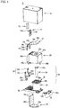
- FIG. 1 is an exploded view of an electromagnetic relay (hereinafter referred to as "relay") 1 according to a present embodiment.
- FIG. 2 is a perspective view of the relay 1.
- the relay 1 is a direct current (DC) high voltage type relay, and is used as a relay for battery pre-charge (prevention of an inrush current to a main relay contact) of an electric vehicle, for example.
- DC high voltage does not mean a high voltage prescribed in IEC (International Electrotechnical Commission) but means a voltage more than 12VDC or 24VDC used in a general car battery, for example.
- the relay 1 has to reliably extinguish an arc generated between a fixed contact and a movable contact at the time of load block of the DC high voltage.
- a polarity is designated to connection of a load side.
- the relay 1 which is the relay for battery pre-charge, current directions reverse each other at the time of battery charging and discharging, and it is therefore required that the polarity of connection of the load side is not designated. Therefore, the relay 1 has to extinguish the arc regardless of a direction of the current flowing between the movable contact and the fixed contact.
- the use of the relay 1 is not limited to the electric vehicle, and the relay 1 can be used for various devices and facilities.
- the relay 1 includes a case 10, a permanent magnet 12 for extinguishing magnetic arc, a hinge spring 14, an armature 16, a movable contact spring 18, an insulating cover 20, fixed contact terminals 22 (22a and 22b), an iron core 24, a spool 26, a base 28, a coil 30, a pair of coil terminals 32 (32a and 32b), and a yoke 34.
- the pair of coil terminals 32 (32a and 32b) supplies a current to excite an electromagnetic device composed of the iron core 24, the spool 26 and the coil 30.
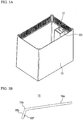
- a magnet holder 101 is formed in the inside of the case 10, and the permanent magnet 12 is held in the magnet holder 101.
- the permanent magnet 12 held in the magnet holder 101 is arranged between the fixed contact terminals 22a and 22b, as illustrated in FIG. 2 .
- the case 10 is omitted.
- a surface having a N-pole of the permanent magnet 12 is directed to a side of the fixed contact terminal 22b, and a surface having a S-pole of the permanent magnet 12 is directed to a side of the fixed contact terminal 22a.
- the positions of the surface having the N-pole and the surface having the S-pole may be reversed each other.
- a samarium cobalt magnet which is superior in residual flux density, coercive force and heat resistance is used as the permanent magnet 12, for example. Especially, since the heat of the arc reaches the permanent magnet 12, the samarium cobalt magnet which is superior in the heat resistance to a neodymium magnet is used.
- the hinge spring 14 is formed in an inverted L-shape in a side view, and includes a horizontal portion 14a that biases a suspended portion 16b of the armature 16 downward, and a suspended portion 14b that is fixed to a vertical portion 34b of the yoke 34.
- the armature 16 is a magnetic body having a dogleg-shaped in a side view, and includes a flat plate portion 16a that is attracted by the iron core 24, and the suspended portion 16b extending downward from the flat plate portion 16a via a bent portion 16c, as illustrated in FIG. 3B . Moreover, a through-hole 16d is formed in the center of the bent portion 16c so that the horizontal portion 14a of the hinge spring 14 protrudes, as illustrated in FIGs. 1 and 2 . Cutout portions 16e into which projecting portions 34c of the yoke 34 are fitted are formed on the flat plate portion 16a. Projections 16f for fixing the movable contact spring 18 to the suspended portion 16b by caulking are provided on the suspended portion 16b.
- the armature 16 performs rotary motion with the cutout portions 16e, as a fulcrum, into which the projecting portions 34c of the yoke 34 are fitted.
- the iron core 24 attracts the flat plate portion 16a.
- the horizontal portion 14a of the hinge spring 14 contacts the suspended portion 16b and is pushed upward from the suspended portion 16b.
- the suspended portion 16b is pushed down by a restoring force of the horizontal portion 14a of the hinge spring 14. Thereby, the flat plate portion 16a is separated from the iron core 24.
- a surface of the flat plate portion 16a opposite to the iron core 24 or the insulating cover 20 is defined as a first surface, and a rear surface of the first surface is defined as a second surface.
- a surface of the suspended portion 16b opposite to the yoke 34 or the insulating cover 20 is defined as a first surface, and a rear surface of the first surface is defined as a second surface.
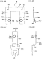
- FIG. 4A is a front view of the movable contact spring 18, and FIG. 4B is a side view of the movable contact spring 18.
- FIG. 4C is a front view of fixed contact terminals 22a and 22b, and
- FIG. 4D is a side view of the fixed contact terminals 22a and 22b.
- the movable contact spring 18 is a conductive plate spring having a U shape in a front view, and includes a pair of movable pieces, i.e., a first movable piece 18a and a second movable piece18b, and a coupling portion 18c that couples upper ends of the first movable piece 18a and the second movable piece 18b with each other.
- the first movable piece 18a and the second movable piece18b are bent at positions 18da and 18db which are nearer to the bottom ends than the centers, respectively.
- a portion below the position 18da of the first movable piece 18a is defined as a lower portion 18a1
- a portion above the position 18da of the first movable piece 18a is defined as an upper portion 18a2.
- a portion below the position 18db of the second movable piece 18b is defined as a lower portion 18b1
- a portion above the position 18db of the second movable piece 18b is defined as an upper portion 18b2.
- a movable contact 36a composed of a material having excellent arc resistance is provided on the lower portion 18a1 of the first movable piece 18a.
- a movable contact 36b composed of a material having excellent arc resistance is provided on the lower portion 18b1 of the second movable piece 18b.
- the upper portion 18a2 of the first movable piece 18a and the upper portion 18b2 of the second movable piece 18b are bent in a direction away from fixed contacts 38a and 38b (i.e., a fixed contact and a second fixed contact) mentioned later which the movable contacts 36a and 36b (i.e., a first movable contact and a second movable contact) contact, respectively.
- the fixed contact terminals 22a and 22b are press-fitted to through-holes, not shown, provided on the base 28 from above, and are fixed to the base 28.
- the fixed contact terminals 22a and 22b are bent like a crank in a side view.
- Each of the fixed contact terminals 22a and 22b includes an upper portion 22e, an inclined portion 22f and a lower portion 22d.
- the upper portion 22e is coupled with the lower portion 22d via the inclined portion 22f, and the upper portion 22e, the inclined portion 22f and the lower portion 22d are integrally formed.
- the lower portion 22d that fixes the fixed contact terminals 22a and 22b to the base 28 functions as a fulcrum.
- the upper portion 22e is bent so as to separate from the movable contact spring 18 or the insulating cover 20 than the lower portion 22d.
- the fixed contacts 38a and 38b composed of a material having excellent arc resistance are provided on the upper portions 22e of the fixed contact terminals 22a and 22b, respectively.
- the insulating cover 20 is made of resin, and a through-hole 20a exposing a head portion 24a of the iron core 24 is formed on a ceiling portion 20e of the insulating cover 20.
- Projection-shaped fixing portions 20b i.e., a first fixing portion
- 20c i.e., a second fixing portion
- the fixing portion 20b engages with one end of the base 28, and the fixing portion 20c is inserted into a hole, not shown, of the base 28.
- a back stop 20d made of resin is integrally formed with the insulating cover 20.
- the back stop 20d As a stopper contacts the movable contact spring 18.
- the occurrence of a collision sound of metal parts such as the movable contact spring 18 and the yoke 34 can be suppressed. Therefore, an operating sound of the relay 1 can be reduced.
- the iron core 24 is inserted into a through-hole 26a formed on a head portion 26b of the spool 26.
- the coil 30 is wound around the spool 26, and integrally formed with the base 28.
- the iron core 24, the spool 26 and the coil 30 constitute the electromagnetic device 31.
- the electromagnetic device 31 attracts the flat plate portion 16a of the armature 16 or release the attraction thereof in accordance with ON/OFF of the current. Thereby, opening or closing action of the movable contact spring 18 against the fixed contact terminals 22a and 22b is carried out.
- the pair of coil terminals 32 is press-fitted into the base 28, and the wiring of the coil 30 is entwined with each of the pair of coil terminals 32.
- the yoke 34 is an L-shaped conductive member in a side view, and includes a horizontal portion 34a that is fixed to a rear surface of the base 28, and the vertical portion 34b that is erected vertically to the horizontal portion 34a.
- the vertical portion 34b is press-fitted into a through-hole, not shown, of the base 28 and a through-hole, not shown, of the insulating cover 20 from the bottom of the base 28.
- the projecting portions 34c provided on both ends of the top of the vertical portion 34b protrude from the ceiling portion 20e of the insulating cover 20, as illustrated in FIG. 2 .
- two plate-like yokes 40a and 40b may be provided, as illustrated in FIG. 5A .
- the yoke 40a is arranged opposite to the surface having the pole (e.g. the S-pole) of the permanent magnet 12, and is arranged so that the permanent magnet 12 and the yoke 40a sandwich the fixed contact terminal 22a.
- the yoke 40b is arranged to opposite to the surface having the pole (e.g. the N-pole) of the permanent magnet 12, and is arranged so that the permanent magnet 12 and the yoke 40b sandwich the fixed contact terminal 22b.
- a U-shaped yoke 39 may be provided, as illustrated in FIG. 5B .
- the yoke 39 is arranged opposite to two surfaces having respective poles of the permanent magnet 12, and is arranged so as to surround the permanent magnet 12 and the fixed contact terminals 22a and 22b.
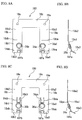
- FIG. 6A is a diagram schematically illustrating a direction of a current flowing into the relay 1, and especially illustrates a state where the fixed contacts and the movable contacts are separated.
- FIG. 6B is a diagram illustrating an arc-extinguishing as viewed from a side of the fixed contact terminal 22a
- FIG. 6C is a diagram illustrating an arc-extinguishing as viewed from a side of the fixed contact terminal 22b.
- a direction (a first direction) in which the current flows is indicated by arrows.
- any one of the fixed contact terminals 22a and 22b is connected to a power supply side, not shown, and the other is connected to a load side, not shown.
- the iron core 24 attracts the flat plate portion 16a, and the armature 16 rotates with the projecting portions 34c and the cutout portions 16e as fulcrums.
- the suspended portion 16b and the movable contact spring 18 fixed to the suspended portion 16b rotate with the rotation of the armature 16, and the movable contacts 36a and 36b contact corresponding fixed contacts 38a and 38b, respectively.
- the movable contacts 36a and 36b begin to separate from the fixed contacts 38a and 38b by the rotation of the armature 16, respectively, the current flowing between the movable contact 36a and the fixed contact 38a and the current flowing between the movable contact 36b and the fixed contact 38b are not completely interrupted, and the arc occurs between the fixed contacts 38a and 38b and the movable contacts 36a and 36b.
- a direction of the magnetic field is a depth direction toward the fixed contact terminal 22b from the fixed contact terminal 22a as illustrated in FIG. 6B in a place where the current flows from the movable contact 36a to the fixed contact 38a. Therefore, the arc which occurs between the movable contact 36a and the fixed contact 38a is extended in a space in a lower direction (a third direction) by Lorentz force as indicated by an arrow A of FIG. 6B and extinguished.
- the direction of the magnetic field is the depth direction toward the fixed contact terminal 22b from the fixed contact terminal 22a as illustrated in FIG. 6C . Therefore, the arc which occurs between the movable contact 36b and the fixed contact 38b is extended in a space in an upper direction (a fourth direction) by Lorentz force as indicated by an arrow B of FIG. 6C and extinguished.
- FIG. 7A is a diagram schematically illustrating a direction of the current flowing into the relay 1.
- FIG. 7B is a diagram illustrating an arc-extinguishing as viewed from the side of the fixed contact terminal 22a
- FIG. 7C is a diagram illustrating an arc-extinguishing as viewed from the side of the fixed contact terminal 22b.
- a direction (a second direction) in which the current flows is indicated by arrows.
- the direction in which the current flows is reversed to the example of FIGs. 6A to 6C .
- any one of the fixed contact terminals 22a and 22b is connected to the power supply side, not shown, and the other is connected to the load side, not shown.
- the iron core 24 attracts the flat plate portion 16a, and the armature 16 rotates with the projecting portions 34c and the cutout portions 16e as fulcrums.
- the suspended portion 16b and the movable contact spring 18 fixed to the suspended portion 16b rotate with the rotation of the armature 16, and the movable contacts 36a and 36b contact corresponding fixed contacts 38a and 38b, respectively.
- the movable contacts 36a and 36b begin to separate from the fixed contacts 38a and 38b by the rotation of the armature 16, respectively, the current flowing between the movable contact 36a and the fixed contact 38a and the current flowing between the movable contact 36b and the fixed contact 38b are not completely interrupted, and the arc occurs between the fixed contacts 38a and 38b and the movable contacts 36a and 36b.
- the direction of the magnetic field is the depth direction toward the fixed contact terminal 22b from the fixed contact terminal 22a as illustrated in FIG. 7B in a place where the current flows from the fixed contact 38a to movable contact 36a. Therefore, the arc which occurs between the movable contact 36a and the fixed contact 38a is extended in a space in the upper direction by Lorentz force as indicated by an arrow A of FIG. 7B and extinguished.
- the direction of the magnetic field is the depth direction toward the fixed contact terminal 22b from the fixed contact terminal 22a as illustrated in FIG. 7C . Therefore, the arc which occurs between the movable contact 36b and the fixed contact 38b is extended in a space in the lower direction by Lorentz force as indicated by an arrow B of FIG. 7C and extinguished.
- the relay 1 of the present embodiment can extend the arc which occurs between the movable contact 36a and the fixed contact 38a and the arc which occurs between the movable contact 36b and the fixed contact 38b in the spaces of the opposite direction at the same time, respectively, and extinguish them, regardless of the directions of the current flowing between the movable contact 36a and the fixed contact 38a and the current flowing between the movable contact 36b and the fixed contact 38b.
- the fulcrums (e.g. the cutout portions 16e) of a movable member including the armature 16 and the movable contact spring 18 are arranged above the movable contacts 36a and 36b or the fixed contacts 38a and 38b, and the fulcrums (e.g. the lower portions 22d) of the fixed contact terminals 22a and 22b are arranged below the movable contacts 36a and 36b or the fixed contacts 38a and 38b. Therefore, even when the arc which occurs between the movable contact 36a and the fixed contact 38a is extended upward or downward according to the direction of the current flowing between the movable contact 36a and the fixed contact 38a, it is possible to secure the spaces for extending the arc.
- FIG. 8A is a front view of a movable contact spring 180
- FIG. 8B is a side view of the movable contact spring 180
- FIG. 8C is a front view of a variation of the movable contact spring 180
- FIG. 8D is a side view of the variation of the movable contact spring 180.
- Components of the movable contact spring 180 identical with those of the movable contact spring 18 of FIGs. 4A and 4B are designated by identical reference numerals.
- the movable contact spring 180 is a conductive plate spring having a U shape in a front view, and includes the pair of movable pieces, i.e., the first movable piece 18a and the second movable piece18b, and the coupling portion 18c that couples upper ends of the first movable piece 18a and the second movable piece 18b with each other.
- the first movable piece 18a is bent twice at the position 18da nearer to the bottom end than the center and a position 18ea nearer to the bottom end than the position 18da.
- the second movable piece 18b is bent twice at the position 18db nearer to the bottom end than the center and a position 18eb nearer to the bottom end than the position 18db.
- a portion below the position 18ea of the first movable piece 18a is defined as a lowest portion 18a3
- a portion between the positions 18ea and 18da is defined as the lower portion 18a1
- a portion above the position 18da of the first movable piece 18a is defined as the upper portion 18a2.
- a portion below the position 18eb of the second movable piece 18b is defined as a lowest portion 18b3
- a portion between the positions 18eb and 18db is defined as the lower portion 18b1
- a portion above the position 18db of the second movable piece 18b is defined as the upper portion 18b2.
- the movable contact 36a composed of the material having excellent arc resistance is provided on the lower portion 18a1 of the first movable piece 18a.
- the movable contact 36b composed of the material having excellent arc resistance is provided on the lower portion 18b1 of the second movable piece 18b.
- the upper portion 18a2 and the lowest portion 18a3 of the first movable piece 18a and the upper portion 18b2 and the lowest portion 18b3 of the second movable piece 18b are bent in a direction away from the fixed contact terminals 22a and 22b, respectively.
- the upper portions 18a2 and 18b2 function as an arc runner which moves the arc generated between the contacts to the space in the upper direction.
- the lowest portions 18a3 and 18b3 function as an arc runner which moves the arc generated between the contacts to the space in the lower direction.
- a cut-and-raised portion 18fa (a first cut-and-raised portion) that projects toward the movable contact 36a from the lowest portion 18a3 along a surface of the lowest portion 18a3 and inclines with respect to the lower portion 18a1.
- a cut-and-raised portion 18fb (the first cut-and-raised portion) that projects toward the movable contact 36b from the lowest portion 18b3 along a surface of the lowest portion 18b3 and inclines with respect to the lower portion 18b1.
- the cut-and-raised portions 18fa and 18fb coupled with the lowest portions 18a3 and 18b3 a distance between the movable contact 36a and the lowest portion 18a3 (i.e., a member other than the contact) and a distance between the movable contact 36b and the lowest portion 18b3 are reduced. Therefore, the arc generated between the movable contact 36a and the fixed contact 38a and the arc generated between the movable contact 36b and the fixed contact 38b can quickly move from these contacts to the lowest portions 18a3 and 18b3 (i.e., the member other than the contact), respectively. Therefore, the cut-and-raised portions 18fa and 18fb can suppress the wear of the contacts.
- formed on the first movable piece 18a may be a cut-and-raised portion 18ga (a second cut-and-raised portion) that projects toward the movable contact 36a from the upper portion 18a2 so as to incline with respect to the lower portion 18a1 along a surface of the upper portion 18a2, as illustrated in FIGs. 8C and 8D .
- formed on the second movable piece 18b may be a cut-and-raised portion 18gb (the second cut-and-raised portion) that projects toward the movable contact 36b from the upper portion 18b2 so as to incline with respect to the lower portion 18b1 along a surface of the upper portion 18b2.
- FIG. 9A is a front view of fixed contact terminals 220a and 220b
- FIG. 9B is a side view of the fixed contact terminals 220a and 220b.
- Components of the fixed contact terminals 220a and 220b identical with those of the fixed contact terminals 22a and 22b of FIGs. 4C and 4D are designated by identical reference numerals.
- the fixed contact terminals 220a and 220b are press-fitted to through-holes, not shown, provided on the base 28 from above, and are fixed to the base 28.
- the fixed contact terminals 220a and 220b are bent like a crank in a side view.
- Each of the fixed contact terminals 220a and 220b includes an uppermost portion 22g, the upper portion 22e, the inclined portion 22f and the lower portion 22d.
- the lower portion 22d that fixes the fixed contact terminals 220a and 220b to the base 28 functions as the fulcrum.
- the upper portion 22e is bent so as to separate from the movable contact spring 180 or the insulating cover 20 than the lower portion 22d.
- the fixed contacts 38a and 38b composed of a material having excellent arc resistance are provided on the upper portions 22e of the fixed contact terminals 220a and 220b, respectively.
- the fixed contact terminals 220a and 220b are different in the inclusion of the uppermost portion 22g from the fixed contact terminals 22a and 22b of FIG. 4C .
- the uppermost portion 22g is formed by bending the fixed contact terminals 220a and 220b at a position 22h higher than the fixed contacts 38a and 38b.
- a portion above the position 22h is the uppermost portion 22g
- a portion between the position 22h and the inclined portion 22f is the upper portion 22e.
- the uppermost portion 22g is bent so as to separate from the movable contact spring 180 or the insulating cover 20 than the upper portion 22e.
- the uppermost portions 22g functions as an arc runner which moves the arc generated between the contacts to the space in the upper direction.
- a cut-and-raised portion 22i (a third cut-and-raised portion) that projects toward the fixed contacts 38a and 38b from the uppermost portion 22g so as to incline with respect to the upper portion 22e along a surface of the uppermost portion 22g.
- FIG. 10A is a diagram illustrating an arc-extinguishing as viewed from the side of the fixed contact terminal 220a
- FIG. 10B is a diagram illustrating an arc-extinguishing as viewed from the side of the fixed contact terminal 220b.
- a direction in which the current flows is indicates by arrows.
- the first movable piece 18a and the second movable piece 18b are bent in a direction in which the upper portion 18a2 and the lowest portion 18a3 of the first movable piece 18a and the upper portion 18b2 and the lowest portion 18b3 of the second movable piece 18b separate from the fixed contact terminals 220a and 220b opposite to the movable contacts 36a and 36b, respectively.
- the uppermost portion 22g of the fixed contact terminals 220a and 220b is bent in the direction away from the movable contact spring 180 or the insulating cover 20.
- the uppermost portion 22g, the upper portion 18a2 and the upper portion 18b2 can quickly move the arc generated between the movable contact 36a and the fixed contact 38a and the arc generated between the movable contact 36b and the fixed contact 38b to the space in the upper direction, and can reduce the wear of the movable contacts 36a and 36b and the fixed contacts 38a and 38b.
- a gap between the uppermost portion 22g and the upper portions 18a2 and 18b2 gradually spreads as going to the upper direction of FIGs. 10A and 10B .
- a gap between the fixed contact terminal 220a and the lowest portion 18b3 gradually spreads as going to the lower direction of FIGs. 10A and 10B .
- the lowest portion 18a3 and 18b3 can quickly move the arc generated between the movable contact 36a and the fixed contact 38a and the arc generated between the movable contact 36b and the fixed contact 38b to the space in the lower direction, and can reduce the wear of the movable contacts 36a and 36b and the fixed contacts 38a and 38b.
- the cut-and-raised portion 22i is formed toward the fixed contacts 38a and 38b from the uppermost portion 22g functioning as the arc runner, so that the arc can be quickly moved to the arc runner, and the wear of the fixed contacts 38a and 38b can be reduced.
- a reason why the formation of the cut-and-raised portions can quickly move the arc to the arc runner is that a distance in which the arc moves from the fixed contacts or the movable contacts to a member other than their contacts (here, the cut-and-raised portions coupled with the arc runner) is reduced compared with a case where the cut-and-raised portions are not formed.
- the cut-and-raised portions 18ga and 18fa are formed toward the movable contact 36a from the upper portion 18a2 functioning as the arc runner and the lowest portion 18a3, so that the arc can be quickly moved to the arc runner, and the wear of the movable contact 36a can be reduced.
- the cut-and-raised portions 18gb and 18fb are formed toward the movable contact 36b from the upper portion 18b2 functioning as the arc runner and the lowest portion 18b3, so that the arc can be quickly moved to the arc runner, and the wear of the movable contact 36b can be reduced.
- FIG. 11 is a cross-portion view of the relay 1.
- the relay 1 is a direct current high voltage type relay. It is necessary to secure an insulating distance (i.e., a space and a creepage distance) between a strong electrical side (specifically, the armature 16, the movable contact spring 18, the fixed contact terminals 22a and 22b, the iron core 24 and the yoke 34) into which the current as a power to be supplied to a load flows, and a weak electrical side (specifically, the coil 30) into which a current for exciting the electromagnet flows.
- a strong electrical side specifically, the armature 16, the movable contact spring 18, the fixed contact terminals 22a and 22b, the iron core 24 and the yoke 34
- a weak electrical side specifically, the coil 30
- the spool 26 which is arranged between the head portion 24a of the iron core 24 and the coil 30 includes an uneven portion 26c (a third uneven portion) on the head portion 24a, as illustrated in FIG. 11 .
- the base 28 which is arranged between the coil 30 and the yoke 34 includes an uneven portion 28a (a fourth uneven portion) in its own part.
- an inner wall of the insulating cover 20 includes an uneven portion 20g (a first uneven portion) and an uneven portion 20h (a second uneven portion) at positions opposite to the uneven portion 26c and the uneven portion 28a, respectively.
- the uneven portion 20g of the insulating cover 20 is fitted into the uneven portion 26c of the spool 26. These uneven portions are provided, so that the sufficient insulating distance can be secured between the head portion 24a of the iron core 24 and the coil 30 without increasing the relay 1 in size. Moreover, the uneven portion 20h of the insulating cover 20 is fitted into the uneven portion 28a of the base 28. Thereby, the sufficient insulating distance can be secured between the coil 30 and the yoke 34 without increasing the relay 1 in size.
- FIG. 12A is a perspective view of the electromagnetic relay 1 when the case 10 is removed.
- FIG. 12B is a cross-portion view taken along line A-A of FIG. 12A .
- the base 28 includes an uneven portion 28b (a fifth uneven portion) between the fixed contact terminals 220a and 220b, as illustrated in FIG. 12A and 12B .
- irregularities are formed between the fixed contact terminals 220a and 220b, so that the creepage distance between the fixed contact terminals 220a and 220b can be secured, and anti-tracking performance can be improved.
- the fixed contact terminals 220a and 220b are used, but the fixed contact terminals 22a and 22b may be used.
- FIG. 13A is a diagram schematically illustrating the configuration of the base 28 and the pair of coil terminals 32.
- FIG. 13B is a diagram illustrating a state where the pair of coil terminals 32 is pressed into the base 28.
- FIG. 13C is a rear view of the base 28.
- FIG. 13D is a diagram illustrating the coil terminal 32b.
- a side in which the pair of coil terminals 32 is press-fitted is a rear surface of the relay 1.
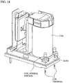
- FIG. 14 is a diagram illustrating a coil terminal mounted on a conventional relay.
- conventional coil terminals have a rod-like shape, and are press-fitted from above the base. Then, coil binding portions of the coil terminal are arranged adjacent to the coil (e.g. see a relay of Japanese Laid-open Patent Publication No. 2013-80692 ). Therefore, to wind the coil, the coil binding portions of the coil terminals are bent in a direction away from the coil. Then, after having finished winding the coil, the bending-back of the coil binding portions is performed to return the coil binding portions to a state illustrated in FIG. 14 . However, the slack and the disconnection of the coil may occur due to the bending-back of the coil binding portions.
- the coil terminal 32a is press-fitted into a T-shaped hole 28c provided on a rear surface of the base 28 in a rear view
- the coil terminal 32b is press-fitted into a T-shaped hole 28d provided on the rear surface of the base 28 in the rear view (see FIG. 13C ).
- the coil terminal 32a is formed by bending a piece of metal plate, and includes a first horizontal portion 50a and a second horizontal portion 51a that are press-fitted into the T-shaped hole 28c and restrict the movement of the coil terminal 32a in a vertical direction, and a vertical portion 52a that restrict the movement of the coil terminal 32a in a horizontal direction.
- the first horizontal portion 50a and the second horizontal portion 51a are provided to invert each other horizontally from a top part of the vertical portion 52a.
- the first horizontal portion 50a and the second horizontal portion 51a are provided so as to be mutually shifted in a longitudinal direction.
- the coil terminal 32a extends vertically downward from the vertical portion 52a, includes: a leg portion 53a that are connected to a power supply, not shown; a coil binding portion 54a that is stood in an oblique direction from one end of the second horizontal portion 51a; and a projecting portion 55a that defines a winding position of the coil 30.
- the coil terminal 32b includes: a first horizontal portion 50b and a second horizontal portion 51b that restrict the movement of the coil terminal 32b in the vertical direction; a vertical portion 52b that restricts the movement of the coil terminal 32b in a horizontal direction; a leg portion 53b that extends vertically downward from the vertical portion 52b, and is connected to the power supply, not shown; a coil binding portion 54b that is stood at a sharp angle from one end of the second horizontal portion 51b; and a projecting portion 55b that defines the winding position of the coil 30 (see FIG. 13D ).
- the base 28 does not exist at positions corresponding to the coil binding portions 54a and 54b, and the coil binding portions 54a and 54b are exposed from the base 28 in a state where the coil terminals 32a and 32b are press-fitted into the base 28. It is preferable that an edge 54a-1 of the coil binding portion 54a and an edge 54b-1 of the coil binding portion 54b are arranged at positions lower than an upper surface 28e of the base 28, as illustrated in FIG. 13B . In this case, the coil 30 can be wound around the spool 26 without considering the coil binding portions 54a and 54b.
- the coil binding portions 54a and 54b are stood at the sharp angle from the horizontal portions (the second horizontal portions 51a and 51b) of the coil terminals 32a and 32b, and hence a space necessary to wind the coil 30 around the spool can be secured. According to the coil terminals 32a and 32b, the bending-back of the coil binding portions is unnecessary, and the slack and the disconnection of the coil 30 can be avoided.
- FIG. 15A is a bottom view of the relay 1 when the case 10 is not mounted.
- FIG. 15B is a bottom view of the relay 1 when the case 10 is mounted.
- the base 28 includes: a recess portion 28f that engages with a projection-shaped fixing portion 20b formed on a bottom of the insulating cover 20; through-holes 28g (a first through-hole) into which projection-shaped fixing portions 20c formed on the bottom of the insulating cover 20 are inserted; through-holes 28h (a second through-hole) into which the fixed contact terminals 22a and 22b are press-fitted; and holes 28i into which the vertical portion 52a of the coil terminal 32a and the vertical portion 52b of the coil terminal 32b are press-fitted.
- the fixed contact terminals 22a and 22b are press-fitted into the through-holes 28h, and the vertical portion 52a of the coil terminal 32a and the vertical portion 52b of the coil terminal 32b are press-fitted into the holes 28i.
- the fixing portion 20b is engaged with the recess portion 28f of the base 28, the fixing portions 20c are inserted into the through-holes 28g of the base 28, and then the case 10 is attached to the base 28 and the bottom of the base 28 is adhered with an adhesive.
- An oblique line portion of FIG. 15B illustrates a portion where the adhesive is applied.
- the insulating cover 20 can be adhered to the base 28 at the same time. Compared with a case where the process of adhering the insulating cover 20 to the base 28 and the process of adhering the fixed contact terminals 22a and 22b and the coil terminals 32a and 32b to the base 28 are performed separately, it is possible to reduce the adhering process and the manufacturing cost.
- the permanent magnet 12 for arc-extinguishing is arranged between the fixed contact terminal 22a and the first movable piece 18a, and the fixed contact terminal 22b and the second movable piece 18b.
- the fulcrums (e.g. the cutout portions 16e) of the movable member including the armature 16 and the movable contact spring 18, and the fulcrums (e.g. the lower portions 22d) of the fixed contact terminals 22a and 22b are arranged mutually in opposite directions with respect to the movable contacts 36a and 36b or the fixed contacts 38a and 38b.
Description
- The present invention relates to an electromagnetic relay and a coil terminal.
- There has been known an electromagnetic relay in which a permanent magnet for extinguishing a magnetic arc generates a magnetic flux between relay contacts and an arc generated between the relay contacts is extended by Lorentz force and extinguished. For example, each of electromagnetic relays of Patent Documents 1-4 is known as an electromagnetic relay including a plurality of permanent magnets for extinguishing the magnetic arc. Moreover, each of electromagnetic relays of Patent Documents 2, 3 and 5-7 is known as an electromagnetic relay extending the arc in a single direction.
-
- [Patent Document 1] Japanese Laid-open Patent Publication No.
2013-196783 - [Patent Document 2] Japanese Patent No.
5085754 - [Patent Document 3] Japanese Patent No.
4810937 - [Patent Document 4] Japanese Laid-open Patent Publication No.
2000-67725 - [Patent Document 5] Japanese Patent No.
5202072 - [Patent Document 6] Utility Model Application Laid-Open Publication No.
63-157143 - [Patent Document 7] Japanese Laid-open Patent Publication No.
10-326553 - [Patent Document 8]
EP 2 672 497 A1 discloses an electromagnetic relay including an armature that oscillates according to excitation and non-excitation of an electromagnetic block, movable contact members provided with movable contact points and attached to the armature to move in association with the moving armature, and fixed contact members provided with fixed contact points with and from which the movable contact points come into contact and separate. - Each of electromagnetic relays of above-mentioned Patent Documents 1-4 includes the plurality of permanent magnets for extinguishing the magnetic arc, and therefore there is a problem that a manufacturing cost increases, compared with an electromagnetic relay including a single permanent magnet for extinguishing the magnetic arc.
- Each of electromagnetic relays of above-mentioned Patent Documents 2, 3 and 5-7 extends the arc in a single direction. However, the arc may not be extended effectively according to the direction of a current flowing between a fixed contact and a movable contact. That is, in each of the electromagnetic relays of above-mentioned Patent Documents 2, 3 and 5-7, there is a problem that a difference occurs in an extinguishing capability of the arc according to the direction of the current flowing between the movable contact and the fixed contact.
- It is an object of the present invention to provide an electromagnetic relay and a coil terminal that can extinguish the arc effectively regardless of the direction of the current flowing between the movable contact and the fixed contact, and reduce the manufacturing cost.
- The invention is defined in the independent claim, to which reference should now be made. Advantageous embodiments are set out in the dependent claims.
- According to the present invention, it is possible to extinguish the arc effectively regardless of the direction of the current flowing between the movable contact and the fixed contact, and reduce the manufacturing cost.
-
-
FIG. 1 is an exploded view of an electromagnetic relay (relay) 1 according to a present embodiment; -
FIG. 2 is a perspective view of therelay 1; -
FIG. 3A is a diagram illustrating internal structure of acase 10; -
FIG. 3B is a side view of anarmature 16; -
FIG. 4A is a front view of amovable contact spring 18; -
FIG. 4B is a side view of themovable contact spring 18; -
FIG. 4C is a front view of fixedcontact terminals -
FIG. 4D is a side view of thefixed contact terminals -
FIGs. 5A and 5B are diagrams illustrating variations of therelay 1; -
FIG. 6A is a diagram schematically illustrating a direction of a current flowing into therelay 1; -
FIG. 6B is a diagram illustrating an arc-extinguishing as viewed from a side of thefixed contact terminal 22a; -
FIG. 6C is a diagram illustrating an arc-extinguishing as viewed from a side of thefixed contact terminal 22b; -
FIG. 7A is a diagram schematically illustrating a direction of a current flowing into therelay 1; -
FIG. 7B is a diagram illustrating an arc-extinguishing as viewed from the side of thefixed contact terminal 22a; -
FIG. 7C is a diagram illustrating an arc-extinguishing as viewed from the side of thefixed contact terminal 22b; -
FIG. 8A is a front view of amovable contact spring 180; -
FIG. 8B is a side view of themovable contact spring 180; -
FIG. 8C is a front view of a variation of themovable contact spring 180; -
FIG. 8D is a side view of the variation of themovable contact spring 180; -
FIG. 9A is a front view of fixedcontact terminals -
FIG. 9B is a side view of the fixedcontact terminals -
FIG. 10A is a diagram illustrating an arc-extinguishing as viewed from a side of the fixedcontact terminal 220a; -
FIG. 10B is a diagram illustrating an arc-extinguishing as viewed from a side of the fixedcontact terminal 220b; -
FIG. 11 is a cross-portion view of therelay 1; -
FIG. 12A is a perspective view of theelectromagnetic relay 1 when thecase 10 is removed; -
FIG. 12B is a cross-portion view taken along line A-A ofFIG. 12A ; -
FIG. 13A is a diagram schematically illustrating the configuration of abase 28 and a pair ofcoil terminals 32; -
FIG. 13B is a diagram illustrating a state where the pair ofcoil terminals 32 is pressed into thebase 28; -
FIG. 13C is a rear view of thebase 28; -
FIG. 13D is a diagram illustrating acoil terminal 32b; -
FIG. 14 is a diagram illustrating a coil terminal mounted on a conventional relay; -
FIG. 15A is a bottom view of therelay 1 when thecase 10 is not mounted; and -
FIG. 15B is a bottom view of therelay 1 when thecase 10 is mounted. - Hereinafter, a description will be given of embodiments with drawings.
-
FIG. 1 is an exploded view of an electromagnetic relay (hereinafter referred to as "relay") 1 according to a present embodiment.FIG. 2 is a perspective view of therelay 1. - The
relay 1 according to the present embodiment is a direct current (DC) high voltage type relay, and is used as a relay for battery pre-charge (prevention of an inrush current to a main relay contact) of an electric vehicle, for example. Here, the DC high voltage does not mean a high voltage prescribed in IEC (International Electrotechnical Commission) but means a voltage more than 12VDC or 24VDC used in a general car battery, for example. - The
relay 1 has to reliably extinguish an arc generated between a fixed contact and a movable contact at the time of load block of the DC high voltage. In the general DC high voltage type relay, a polarity is designated to connection of a load side. However, in therelay 1 which is the relay for battery pre-charge, current directions reverse each other at the time of battery charging and discharging, and it is therefore required that the polarity of connection of the load side is not designated. Therefore, therelay 1 has to extinguish the arc regardless of a direction of the current flowing between the movable contact and the fixed contact. Here, the use of therelay 1 is not limited to the electric vehicle, and therelay 1 can be used for various devices and facilities. - As illustrated in
FIG. 1 , therelay 1 includes acase 10, apermanent magnet 12 for extinguishing magnetic arc, ahinge spring 14, anarmature 16, amovable contact spring 18, an insulatingcover 20, fixed contact terminals 22 (22a and 22b), aniron core 24, aspool 26, abase 28, acoil 30, a pair of coil terminals 32 (32a and 32b), and ayoke 34. The pair of coil terminals 32 (32a and 32b) supplies a current to excite an electromagnetic device composed of theiron core 24, thespool 26 and thecoil 30. - As illustrated in
FIG. 3A , amagnet holder 101 is formed in the inside of thecase 10, and thepermanent magnet 12 is held in themagnet holder 101. Thepermanent magnet 12 held in themagnet holder 101 is arranged between thefixed contact terminals FIG. 2 . InFIG. 2 , thecase 10 is omitted. For example, a surface having a N-pole of thepermanent magnet 12 is directed to a side of the fixedcontact terminal 22b, and a surface having a S-pole of thepermanent magnet 12 is directed to a side of the fixedcontact terminal 22a. The positions of the surface having the N-pole and the surface having the S-pole may be reversed each other. Moreover, a samarium cobalt magnet which is superior in residual flux density, coercive force and heat resistance is used as thepermanent magnet 12, for example. Especially, since the heat of the arc reaches thepermanent magnet 12, the samarium cobalt magnet which is superior in the heat resistance to a neodymium magnet is used. - Referring to
FIG. 1 , thehinge spring 14 is formed in an inverted L-shape in a side view, and includes ahorizontal portion 14a that biases a suspendedportion 16b of thearmature 16 downward, and a suspendedportion 14b that is fixed to avertical portion 34b of theyoke 34. - The
armature 16 is a magnetic body having a dogleg-shaped in a side view, and includes aflat plate portion 16a that is attracted by theiron core 24, and the suspendedportion 16b extending downward from theflat plate portion 16a via abent portion 16c, as illustrated inFIG. 3B . Moreover, a through-hole 16d is formed in the center of thebent portion 16c so that thehorizontal portion 14a of thehinge spring 14 protrudes, as illustrated inFIGs. 1 and2 .Cutout portions 16e into which projectingportions 34c of theyoke 34 are fitted are formed on theflat plate portion 16a.Projections 16f for fixing themovable contact spring 18 to the suspendedportion 16b by caulking are provided on the suspendedportion 16b. - The
armature 16 performs rotary motion with thecutout portions 16e, as a fulcrum, into which the projectingportions 34c of theyoke 34 are fitted. When a current flows into thecoil 30, theiron core 24 attracts theflat plate portion 16a. At this time, thehorizontal portion 14a of thehinge spring 14 contacts the suspendedportion 16b and is pushed upward from the suspendedportion 16b. When the current of thecoil 30 is cut off, the suspendedportion 16b is pushed down by a restoring force of thehorizontal portion 14a of thehinge spring 14. Thereby, theflat plate portion 16a is separated from theiron core 24. Here, a surface of theflat plate portion 16a opposite to theiron core 24 or the insulatingcover 20 is defined as a first surface, and a rear surface of the first surface is defined as a second surface. Moreover, a surface of the suspendedportion 16b opposite to theyoke 34 or the insulatingcover 20 is defined as a first surface, and a rear surface of the first surface is defined as a second surface. -
FIG. 4A is a front view of themovable contact spring 18, andFIG. 4B is a side view of themovable contact spring 18.FIG. 4C is a front view offixed contact terminals FIG. 4D is a side view of the fixedcontact terminals - The
movable contact spring 18 is a conductive plate spring having a U shape in a front view, and includes a pair of movable pieces, i.e., a firstmovable piece 18a and a second movable piece18b, and acoupling portion 18c that couples upper ends of the firstmovable piece 18a and the secondmovable piece 18b with each other. - The first
movable piece 18a and the second movable piece18b are bent at positions 18da and 18db which are nearer to the bottom ends than the centers, respectively. Here, a portion below the position 18da of the firstmovable piece 18a is defined as a lower portion 18a1, and a portion above the position 18da of the firstmovable piece 18a is defined as an upper portion 18a2. Similarly, a portion below the position 18db of the secondmovable piece 18b is defined as a lower portion 18b1, and a portion above the position 18db of the secondmovable piece 18b is defined as an upper portion 18b2. - A
movable contact 36a composed of a material having excellent arc resistance is provided on the lower portion 18a1 of the firstmovable piece 18a. Amovable contact 36b composed of a material having excellent arc resistance is provided on the lower portion 18b1 of the secondmovable piece 18b. In the firstmovable piece 18a and the secondmovable piece 18b, the upper portion 18a2 of the firstmovable piece 18a and the upper portion 18b2 of the secondmovable piece 18b are bent in a direction away from fixedcontacts movable contacts - Through-
holes 18e into which theprojections 16f provided on the suspendedportion 16b are fitted are formed on thecoupling portion 18c. Theprojections 16f are fitted and caulked into the through-holes 18e, so that themovable contact spring 18 is fixed to the first surface of the suspendedportion 16b of thearmature 16. - The fixed
contact terminals base 28. The fixedcontact terminals contact terminals upper portion 22e, aninclined portion 22f and alower portion 22d. Theupper portion 22e is coupled with thelower portion 22d via theinclined portion 22f, and theupper portion 22e, theinclined portion 22f and thelower portion 22d are integrally formed. Thelower portion 22d that fixes the fixedcontact terminals upper portion 22e is bent so as to separate from themovable contact spring 18 or the insulatingcover 20 than thelower portion 22d. The fixedcontacts upper portions 22e of the fixedcontact terminals bifurcated terminal 22c to be connected to a power supply, not shown, is provided on thelower portions 22d of the fixedcontact terminals - Referring to
FIG. 1 , the insulatingcover 20 is made of resin, and a through-hole 20a exposing ahead portion 24a of theiron core 24 is formed on aceiling portion 20e of the insulatingcover 20. Projection-shapedfixing portions 20b (i.e., a first fixing portion) and 20c (i.e., a second fixing portion) are formed on a bottom portion of the insulatingcover 20 to fix the insulatingcover 20 to thebase 28. The fixingportion 20b engages with one end of thebase 28, and the fixingportion 20c is inserted into a hole, not shown, of thebase 28. Moreover, aback stop 20d made of resin is integrally formed with the insulatingcover 20. When the current does not flow into the coil 30 (i.e., when anelectromagnetic device 31 mentioned later is OFF), theback stop 20d as a stopper contacts themovable contact spring 18. By theback stop 20d, the occurrence of a collision sound of metal parts such as themovable contact spring 18 and theyoke 34 can be suppressed. Therefore, an operating sound of therelay 1 can be reduced. - The
iron core 24 is inserted into a through-hole 26a formed on ahead portion 26b of thespool 26. Thecoil 30 is wound around thespool 26, and integrally formed with thebase 28. Theiron core 24, thespool 26 and thecoil 30 constitute theelectromagnetic device 31. Theelectromagnetic device 31 attracts theflat plate portion 16a of thearmature 16 or release the attraction thereof in accordance with ON/OFF of the current. Thereby, opening or closing action of themovable contact spring 18 against the fixedcontact terminals coil terminals 32 is press-fitted into thebase 28, and the wiring of thecoil 30 is entwined with each of the pair ofcoil terminals 32. - The
yoke 34 is an L-shaped conductive member in a side view, and includes ahorizontal portion 34a that is fixed to a rear surface of thebase 28, and thevertical portion 34b that is erected vertically to thehorizontal portion 34a. Thevertical portion 34b is press-fitted into a through-hole, not shown, of thebase 28 and a through-hole, not shown, of the insulatingcover 20 from the bottom of thebase 28. Thereby, the projectingportions 34c provided on both ends of the top of thevertical portion 34b protrude from theceiling portion 20e of the insulatingcover 20, as illustrated inFIG. 2 . - Here, to stabilize a direction of the magnetic flux of the
permanent magnet 12 and to reduce leak magnetic flux, two plate-like yokes FIG. 5A . In this case, theyoke 40a is arranged opposite to the surface having the pole (e.g. the S-pole) of thepermanent magnet 12, and is arranged so that thepermanent magnet 12 and theyoke 40a sandwich the fixedcontact terminal 22a. Theyoke 40b is arranged to opposite to the surface having the pole (e.g. the N-pole) of thepermanent magnet 12, and is arranged so that thepermanent magnet 12 and theyoke 40b sandwich the fixedcontact terminal 22b. Alternatively, to stabilize the direction of the magnetic flux of thepermanent magnet 12 and to reduce the leak magnetic flux, aU-shaped yoke 39 may be provided, as illustrated inFIG. 5B . In this case, theyoke 39 is arranged opposite to two surfaces having respective poles of thepermanent magnet 12, and is arranged so as to surround thepermanent magnet 12 and the fixedcontact terminals -
FIG. 6A is a diagram schematically illustrating a direction of a current flowing into therelay 1, and especially illustrates a state where the fixed contacts and the movable contacts are separated.FIG. 6B is a diagram illustrating an arc-extinguishing as viewed from a side of the fixedcontact terminal 22a, andFIG. 6C is a diagram illustrating an arc-extinguishing as viewed from a side of the fixedcontact terminal 22b. InFIGs. 6A to 6C , a direction (a first direction) in which the current flows is indicated by arrows. - In
FIG. 6A , any one of the fixedcontact terminals coil 30, theiron core 24 attracts theflat plate portion 16a, and thearmature 16 rotates with the projectingportions 34c and thecutout portions 16e as fulcrums. The suspendedportion 16b and themovable contact spring 18 fixed to the suspendedportion 16b rotate with the rotation of thearmature 16, and themovable contacts contacts contact terminal 22b in a state where themovable contacts contacts contact terminal 22b, the fixedcontact 38b, themovable contact 36b, the secondmovable piece 18b, thecoupling portion 18c, the firstmovable piece 18a, themovable contact 36a, the fixedcontact 38a and the fixedcontact terminal 22a in this order, as illustrated inFIG. 6A . Then, when the current which flows into thecoil 30 is cut off, thearmature 16 rotates counterclockwise illustrated inFIG. 6B by the restoring force of thehinge spring 14. Although themovable contacts contacts armature 16, respectively, the current flowing between themovable contact 36a and the fixedcontact 38a and the current flowing between themovable contact 36b and the fixedcontact 38b are not completely interrupted, and the arc occurs between the fixedcontacts movable contacts - In the
relay 1 illustrated inFIGs. 6A to 6C , a direction of the magnetic field is a depth direction toward the fixedcontact terminal 22b from the fixedcontact terminal 22a as illustrated inFIG. 6B in a place where the current flows from themovable contact 36a to the fixedcontact 38a. Therefore, the arc which occurs between themovable contact 36a and the fixedcontact 38a is extended in a space in a lower direction (a third direction) by Lorentz force as indicated by an arrow A ofFIG. 6B and extinguished. On the other hand, in a place where the current flows from the fixedcontact 38b to themovable contact 36b, the direction of the magnetic field is the depth direction toward the fixedcontact terminal 22b from the fixedcontact terminal 22a as illustrated inFIG. 6C . Therefore, the arc which occurs between themovable contact 36b and the fixedcontact 38b is extended in a space in an upper direction (a fourth direction) by Lorentz force as indicated by an arrow B ofFIG. 6C and extinguished. -
FIG. 7A is a diagram schematically illustrating a direction of the current flowing into therelay 1.FIG. 7B is a diagram illustrating an arc-extinguishing as viewed from the side of the fixedcontact terminal 22a, andFIG. 7C is a diagram illustrating an arc-extinguishing as viewed from the side of the fixedcontact terminal 22b. InFIGs. 7A to 7C , a direction (a second direction) in which the current flows is indicated by arrows. Here, the direction in which the current flows is reversed to the example ofFIGs. 6A to 6C . - In
FIG. 7A , as withFIG. 6A , any one of the fixedcontact terminals coil 30, theiron core 24 attracts theflat plate portion 16a, and thearmature 16 rotates with the projectingportions 34c and thecutout portions 16e as fulcrums. The suspendedportion 16b and themovable contact spring 18 fixed to the suspendedportion 16b rotate with the rotation of thearmature 16, and themovable contacts contacts contact terminal 22a in a state where themovable contacts contacts contact terminal 22a, the fixedcontact 38a, themovable contact 36a, the firstmovable piece 18a, thecoupling portion 18c, the second movable piece18b, themovable contact 36b, the fixedcontact 38b and the fixedcontact terminal 22b in this order, as illustrated inFIG. 7A . Then, when the current which flows into thecoil 30 is cut off, thearmature 16 rotates counterclockwise illustrated inFIG. 7B by the restoring force of thehinge spring 14. Although themovable contacts contacts armature 16, respectively, the current flowing between themovable contact 36a and the fixedcontact 38a and the current flowing between themovable contact 36b and the fixedcontact 38b are not completely interrupted, and the arc occurs between the fixedcontacts movable contacts - In the
relay 1 illustrated inFIGs. 7A to 7C , the direction of the magnetic field is the depth direction toward the fixedcontact terminal 22b from the fixedcontact terminal 22a as illustrated inFIG. 7B in a place where the current flows from the fixedcontact 38a tomovable contact 36a. Therefore, the arc which occurs between themovable contact 36a and the fixedcontact 38a is extended in a space in the upper direction by Lorentz force as indicated by an arrow A ofFIG. 7B and extinguished. On the other hand, in a place where the current flows from themovable contact 36b to the fixedcontact 38b, the direction of the magnetic field is the depth direction toward the fixedcontact terminal 22b from the fixedcontact terminal 22a as illustrated inFIG. 7C . Therefore, the arc which occurs between themovable contact 36b and the fixedcontact 38b is extended in a space in the lower direction by Lorentz force as indicated by an arrow B ofFIG. 7C and extinguished. - Therefore, according to
FIGs. 6A to 7C , therelay 1 of the present embodiment can extend the arc which occurs between themovable contact 36a and the fixedcontact 38a and the arc which occurs between themovable contact 36b and the fixedcontact 38b in the spaces of the opposite direction at the same time, respectively, and extinguish them, regardless of the directions of the current flowing between themovable contact 36a and the fixedcontact 38a and the current flowing between themovable contact 36b and the fixedcontact 38b. - The fulcrums (e.g. the
cutout portions 16e) of a movable member including thearmature 16 and themovable contact spring 18 are arranged above themovable contacts contacts lower portions 22d) of the fixedcontact terminals movable contacts contacts movable contact 36a and the fixedcontact 38a is extended upward or downward according to the direction of the current flowing between themovable contact 36a and the fixedcontact 38a, it is possible to secure the spaces for extending the arc. Similarly, even when the arc which occurs between themovable contact 36b and the fixedcontact 38b is extended upward or downward according to the direction of the current flowing between themovable contact 36b and the fixedcontact 38b, it is possible to secure the spaces for extending the arc. - In the following, a description will be given of a variation of the
movable contact spring 18 and a variation of the fixedcontact terminals -
FIG. 8A is a front view of amovable contact spring 180, andFIG. 8B is a side view of themovable contact spring 180.FIG. 8C is a front view of a variation of themovable contact spring 180, andFIG. 8D is a side view of the variation of themovable contact spring 180. Components of themovable contact spring 180 identical with those of themovable contact spring 18 ofFIGs. 4A and 4B are designated by identical reference numerals. - The
movable contact spring 180 is a conductive plate spring having a U shape in a front view, and includes the pair of movable pieces, i.e., the firstmovable piece 18a and the second movable piece18b, and thecoupling portion 18c that couples upper ends of the firstmovable piece 18a and the secondmovable piece 18b with each other. - The first
movable piece 18a is bent twice at the position 18da nearer to the bottom end than the center and a position 18ea nearer to the bottom end than the position 18da. The secondmovable piece 18b is bent twice at the position 18db nearer to the bottom end than the center and a position 18eb nearer to the bottom end than the position 18db. Here, a portion below the position 18ea of the firstmovable piece 18a is defined as a lowest portion 18a3, a portion between the positions 18ea and 18da is defined as the lower portion 18a1, and a portion above the position 18da of the firstmovable piece 18a is defined as the upper portion 18a2. Similarly, a portion below the position 18eb of the secondmovable piece 18b is defined as a lowest portion 18b3, a portion between the positions 18eb and 18db is defined as the lower portion 18b1, and a portion above the position 18db of the secondmovable piece 18b is defined as the upper portion 18b2. - The
movable contact 36a composed of the material having excellent arc resistance is provided on the lower portion 18a1 of the firstmovable piece 18a. Themovable contact 36b composed of the material having excellent arc resistance is provided on the lower portion 18b1 of the secondmovable piece 18b. In the firstmovable piece 18a and the secondmovable piece 18b, the upper portion 18a2 and the lowest portion 18a3 of the firstmovable piece 18a and the upper portion 18b2 and the lowest portion 18b3 of the secondmovable piece 18b are bent in a direction away from the fixedcontact terminals - The upper portions 18a2 and 18b2 function as an arc runner which moves the arc generated between the contacts to the space in the upper direction. The lowest portions 18a3 and 18b3 function as an arc runner which moves the arc generated between the contacts to the space in the lower direction.
- Through-
holes 18e into which theprojections 16f provided on the suspendedportion 16b are fitted are formed on thecoupling portion 18c. Theprojections 16f are fitted and caulked into the through-holes 18e, so that themovable contact spring 18 is fixed to the first surface of the suspendedportion 16b of thearmature 16. - Formed on the first
movable piece 18a is a cut-and-raised portion 18fa (a first cut-and-raised portion) that projects toward themovable contact 36a from the lowest portion 18a3 along a surface of the lowest portion 18a3 and inclines with respect to the lower portion 18a1. Moreover, formed on the secondmovable piece 18b is a cut-and-raised portion 18fb (the first cut-and-raised portion) that projects toward themovable contact 36b from the lowest portion 18b3 along a surface of the lowest portion 18b3 and inclines with respect to the lower portion 18b1. By the cut-and-raised portions 18fa and 18fb coupled with the lowest portions 18a3 and 18b3, a distance between themovable contact 36a and the lowest portion 18a3 (i.e., a member other than the contact) and a distance between themovable contact 36b and the lowest portion 18b3 are reduced. Therefore, the arc generated between themovable contact 36a and the fixedcontact 38a and the arc generated between themovable contact 36b and the fixedcontact 38b can quickly move from these contacts to the lowest portions 18a3 and 18b3 (i.e., the member other than the contact), respectively. Therefore, the cut-and-raised portions 18fa and 18fb can suppress the wear of the contacts. - Moreover, formed on the first
movable piece 18a may be a cut-and-raised portion 18ga (a second cut-and-raised portion) that projects toward themovable contact 36a from the upper portion 18a2 so as to incline with respect to the lower portion 18a1 along a surface of the upper portion 18a2, as illustrated inFIGs. 8C and 8D . In addition, formed on the secondmovable piece 18b may be a cut-and-raised portion 18gb (the second cut-and-raised portion) that projects toward themovable contact 36b from the upper portion 18b2 so as to incline with respect to the lower portion 18b1 along a surface of the upper portion 18b2. -
FIG. 9A is a front view offixed contact terminals FIG. 9B is a side view of the fixedcontact terminals contact terminals contact terminals FIGs. 4C and 4D are designated by identical reference numerals. - The fixed
contact terminals base 28. The fixedcontact terminals contact terminals uppermost portion 22g, theupper portion 22e, theinclined portion 22f and thelower portion 22d. Thelower portion 22d that fixes the fixedcontact terminals upper portion 22e is bent so as to separate from themovable contact spring 180 or the insulatingcover 20 than thelower portion 22d. The fixedcontacts upper portions 22e of the fixedcontact terminals bifurcated terminal 22c to be connected to the power supply, not shown, is provided on thelower portions 22d of the fixedcontact terminals - The fixed
contact terminals uppermost portion 22g from the fixedcontact terminals FIG. 4C . Theuppermost portion 22g is formed by bending the fixedcontact terminals position 22h higher than the fixedcontacts FIGs. 9A and 9B , a portion above theposition 22h is theuppermost portion 22g, and a portion between theposition 22h and theinclined portion 22f is theupper portion 22e. - The
uppermost portion 22g is bent so as to separate from themovable contact spring 180 or the insulatingcover 20 than theupper portion 22e. Theuppermost portions 22g functions as an arc runner which moves the arc generated between the contacts to the space in the upper direction. Moreover, formed on the fixedcontact terminals portion 22i (a third cut-and-raised portion) that projects toward the fixedcontacts uppermost portion 22g so as to incline with respect to theupper portion 22e along a surface of theuppermost portion 22g. -
FIG. 10A is a diagram illustrating an arc-extinguishing as viewed from the side of the fixedcontact terminal 220a, andFIG. 10B is a diagram illustrating an arc-extinguishing as viewed from the side of the fixedcontact terminal 220b. InFIGs. 10A and 10B , a direction in which the current flows is indicates by arrows. - As illustrated in
FIG. 10A and 10B , the firstmovable piece 18a and the secondmovable piece 18b are bent in a direction in which the upper portion 18a2 and the lowest portion 18a3 of the firstmovable piece 18a and the upper portion 18b2 and the lowest portion 18b3 of the secondmovable piece 18b separate from the fixedcontact terminals movable contacts uppermost portion 22g of the fixedcontact terminals movable contact spring 180 or the insulatingcover 20. - Thereby, the
uppermost portion 22g, the upper portion 18a2 and the upper portion 18b2 can quickly move the arc generated between themovable contact 36a and the fixedcontact 38a and the arc generated between themovable contact 36b and the fixedcontact 38b to the space in the upper direction, and can reduce the wear of themovable contacts contacts uppermost portion 22g and the upper portions 18a2 and 18b2 gradually spreads as going to the upper direction ofFIGs. 10A and 10B . Moreover, a gap between the fixedcontact terminal 220a and the lowest portion 18b3 gradually spreads as going to the lower direction ofFIGs. 10A and 10B . By gradually spreading the gaps, the arc moving upward or downward can be extended in a horizontal direction ofFIGs. 10A and 10B , and be extinguished more effectively. - Similarly, the lowest portion 18a3 and 18b3 can quickly move the arc generated between the
movable contact 36a and the fixedcontact 38a and the arc generated between themovable contact 36b and the fixedcontact 38b to the space in the lower direction, and can reduce the wear of themovable contacts contacts - Then, the cut-and-raised
portion 22i is formed toward the fixedcontacts uppermost portion 22g functioning as the arc runner, so that the arc can be quickly moved to the arc runner, and the wear of the fixedcontacts movable contact 36a from the upper portion 18a2 functioning as the arc runner and the lowest portion 18a3, so that the arc can be quickly moved to the arc runner, and the wear of themovable contact 36a can be reduced. The cut-and-raised portions 18gb and 18fb are formed toward themovable contact 36b from the upper portion 18b2 functioning as the arc runner and the lowest portion 18b3, so that the arc can be quickly moved to the arc runner, and the wear of themovable contact 36b can be reduced. -
FIG. 11 is a cross-portion view of therelay 1. Therelay 1 is a direct current high voltage type relay. It is necessary to secure an insulating distance (i.e., a space and a creepage distance) between a strong electrical side (specifically, thearmature 16, themovable contact spring 18, the fixedcontact terminals iron core 24 and the yoke 34) into which the current as a power to be supplied to a load flows, and a weak electrical side (specifically, the coil 30) into which a current for exciting the electromagnet flows. However, when the insulating distance is provided linearly inside therelay 1, therelay 1 increases in size. - For this reason, the
spool 26 which is arranged between thehead portion 24a of theiron core 24 and thecoil 30 includes anuneven portion 26c (a third uneven portion) on thehead portion 24a, as illustrated inFIG. 11 . Moreover, the base 28 which is arranged between thecoil 30 and theyoke 34 includes anuneven portion 28a (a fourth uneven portion) in its own part. In addition, an inner wall of the insulatingcover 20 includes anuneven portion 20g (a first uneven portion) and an uneven portion 20h (a second uneven portion) at positions opposite to theuneven portion 26c and theuneven portion 28a, respectively. - The
uneven portion 20g of the insulatingcover 20 is fitted into theuneven portion 26c of thespool 26. These uneven portions are provided, so that the sufficient insulating distance can be secured between thehead portion 24a of theiron core 24 and thecoil 30 without increasing therelay 1 in size. Moreover, the uneven portion 20h of the insulatingcover 20 is fitted into theuneven portion 28a of thebase 28. Thereby, the sufficient insulating distance can be secured between thecoil 30 and theyoke 34 without increasing therelay 1 in size. -
FIG. 12A is a perspective view of theelectromagnetic relay 1 when thecase 10 is removed.FIG. 12B is a cross-portion view taken along line A-A ofFIG. 12A . - By dusts generated due to consumption of the
movable contacts contacts fixed contact terminals base 28 includes anuneven portion 28b (a fifth uneven portion) between thefixed contact terminals FIG. 12A and 12B . Thereby, irregularities are formed between thefixed contact terminals fixed contact terminals FIGs. 12A and 12B , the fixedcontact terminals contact terminals -
FIG. 13A is a diagram schematically illustrating the configuration of thebase 28 and the pair ofcoil terminals 32.FIG. 13B is a diagram illustrating a state where the pair ofcoil terminals 32 is pressed into thebase 28.FIG. 13C is a rear view of thebase 28.FIG. 13D is a diagram illustrating thecoil terminal 32b. Here, a side in which the pair ofcoil terminals 32 is press-fitted is a rear surface of therelay 1.FIG. 14 is a diagram illustrating a coil terminal mounted on a conventional relay. - As illustrated in
FIG 14 , conventional coil terminals have a rod-like shape, and are press-fitted from above the base. Then, coil binding portions of the coil terminal are arranged adjacent to the coil (e.g. see a relay of Japanese Laid-open Patent Publication No.2013-80692 FIG. 14 . However, the slack and the disconnection of the coil may occur due to the bending-back of the coil binding portions. - In
coil terminals - The
coil terminal 32a is press-fitted into a T-shapedhole 28c provided on a rear surface of the base 28 in a rear view, and thecoil terminal 32b is press-fitted into a T-shapedhole 28d provided on the rear surface of the base 28 in the rear view (seeFIG. 13C ). - As illustrated in
FIG. 13A , thecoil terminal 32a is formed by bending a piece of metal plate, and includes a firsthorizontal portion 50a and a secondhorizontal portion 51a that are press-fitted into the T-shapedhole 28c and restrict the movement of thecoil terminal 32a in a vertical direction, and avertical portion 52a that restrict the movement of thecoil terminal 32a in a horizontal direction. The firsthorizontal portion 50a and the secondhorizontal portion 51a are provided to invert each other horizontally from a top part of thevertical portion 52a. Moreover, the firsthorizontal portion 50a and the secondhorizontal portion 51a are provided so as to be mutually shifted in a longitudinal direction. - In addition, the
coil terminal 32a extends vertically downward from thevertical portion 52a, includes: aleg portion 53a that are connected to a power supply, not shown; acoil binding portion 54a that is stood in an oblique direction from one end of the secondhorizontal portion 51a; and a projectingportion 55a that defines a winding position of thecoil 30. - As with the
coil terminal 32a, thecoil terminal 32b includes: a firsthorizontal portion 50b and a secondhorizontal portion 51b that restrict the movement of thecoil terminal 32b in the vertical direction; avertical portion 52b that restricts the movement of thecoil terminal 32b in a horizontal direction; aleg portion 53b that extends vertically downward from thevertical portion 52b, and is connected to the power supply, not shown; acoil binding portion 54b that is stood at a sharp angle from one end of the secondhorizontal portion 51b; and a projectingportion 55b that defines the winding position of the coil 30 (seeFIG. 13D ). - As illustrated in
FIG. 13B , thebase 28 does not exist at positions corresponding to thecoil binding portions coil binding portions coil terminals base 28. It is preferable that anedge 54a-1 of thecoil binding portion 54a and anedge 54b-1 of thecoil binding portion 54b are arranged at positions lower than anupper surface 28e of thebase 28, as illustrated inFIG. 13B . In this case, thecoil 30 can be wound around thespool 26 without considering thecoil binding portions - Thus, the
coil binding portions horizontal portions coil terminals coil 30 around the spool can be secured. According to thecoil terminals coil 30 can be avoided. -
FIG. 15A is a bottom view of therelay 1 when thecase 10 is not mounted.FIG. 15B is a bottom view of therelay 1 when thecase 10 is mounted. - As illustrated in
FIG. 15A , thebase 28 includes: arecess portion 28f that engages with a projection-shapedfixing portion 20b formed on a bottom of the insulatingcover 20; through-holes 28g (a first through-hole) into which projection-shapedfixing portions 20c formed on the bottom of the insulatingcover 20 are inserted; through-holes 28h (a second through-hole) into which the fixedcontact terminals holes 28i into which thevertical portion 52a of thecoil terminal 32a and thevertical portion 52b of thecoil terminal 32b are press-fitted. - In the present embodiment, the fixed
contact terminals holes 28h, and thevertical portion 52a of thecoil terminal 32a and thevertical portion 52b of thecoil terminal 32b are press-fitted into theholes 28i. The fixingportion 20b is engaged with therecess portion 28f of thebase 28, the fixingportions 20c are inserted into the through-holes 28g of thebase 28, and then thecase 10 is attached to thebase 28 and the bottom of thebase 28 is adhered with an adhesive. An oblique line portion ofFIG. 15B illustrates a portion where the adhesive is applied. - In this case, in a process of adhering the fixed
contact terminals coil terminals base 28, the insulatingcover 20 can be adhered to the base 28 at the same time. Compared with a case where the process of adhering the insulatingcover 20 to thebase 28 and the process of adhering the fixedcontact terminals coil terminals - As described above, according to the above-mentioned embodiment, in the
hinge type relay 1 that moves themovable contact spring 18 by rotary motion of thearmature 16, thepermanent magnet 12 for arc-extinguishing is arranged between the fixedcontact terminal 22a and the firstmovable piece 18a, and the fixedcontact terminal 22b and the secondmovable piece 18b. The fulcrums (e.g. thecutout portions 16e) of the movable member including thearmature 16 and themovable contact spring 18, and the fulcrums (e.g. thelower portions 22d) of the fixedcontact terminals movable contacts contacts - Thereby, it is possible to extend the arc toward the fulcrums of the movable member, and further to extend the arc toward the fulcrums of the fixed
contact terminals - Some preferred embodiments of the present invention have been described in detail, but the present invention is not limited to these specifically described embodiments but may have various variations and alterations within the scope of the claimed invention.
Claims (11)
- An electromagnetic relay (1) characterized by comprising:a base (28);a pair of fixed terminals (22) each including a fixed contact (22a, 22b) and a first fulcrum (22d) fixed to the base (28);a movable spring (18) including a pair of movable pieces (18a, 18b), each of the movable pieces (18a, 18b) including a movable contact (36a, 36b) contacting and separating from the fixed contact (22a, 22b);an armature (16) that is coupled with the movable spring (18), and moves the movable spring (18) by a rotary motion around a second fulcrum (16e);an electromagnetic device (31) that drives the armature (16); anda permanent magnet (12) that is arranged between the pair of fixed terminals (22) and between the pair of movable pieces (18a, 18b), and generates a magnetic field;wherein the first fulcrum (22d) and the second fulcrum (16e) are arranged on opposite sides of the movable contact (36a, 36b) or the fixed contact (22a, 22b),characterised in that an N-pole of the permanent magnet (12) is directed to a side of one of the pair of fixed terminals (22) so that a first arc generated between the fixed contact (22a, 22b) of the one of the pair of fixed terminals (22) and the movable contact (36a, 36b) of one of the pair of movable pieces (18a, 18b) extends in a direction, andan S-pole of the permanent magnet (12) is directed to a side of another of the pair of the fixed terminals (22) so that a second arc generated between the fixed contact (22a, 22b) of the another of the pair of fixed terminals (22) and the movable contact (36a, 36b) of another of the pair of movable pieces (18a, 18b) extends in an opposite direction to the direction.
- The electromagnetic relay according to claim 1, characterized in that
the first arc extends in the direction and the second arc extends in the opposite direction when a current flows in one direction between the fixed contact (22a, 22b) and the movable contact (36a, 36b), and
the first arc extends in the opposite direction and the second arc extends in the direction when the current flows in another direction between the fixed contact (22a, 22b) and the movable contact (36a, 36b), the another direction being opposite to the one direction. - The electromagnetic relay according to claim 1, characterized in that each of the pair of movable pieces (18a, 18b) includes an upper portion, and a lower portion on which the movable contact (36a, 36b) is mounted and that is bent from the upper portion away from the fixed contact (22a, 22b) opposite to the movable contact (36a, 36b).
- The electromagnetic relay according to claim 3, characterized in that each of the pair of movable pieces (18a, 18b) further includes a lowest portion that is bent from the lower portion.
- The electromagnetic relay according to claim 4, characterized in that each of the pair of movable pieces (18a, 18b) includes a first cut-and-raised portion that projects toward the movable contact (36a, 36b) from the lowest portion.
- The electromagnetic relay according to claim 3, characterized in that each of the pair of movable pieces (18a, 18b) includes a second cut-and-raised portion that projects toward the movable contact (36a, 36b) from the upper portion.
- The electromagnetic relay according to claim 1, characterized in that each of the pair of fixed terminals (22) includes a second upper portion on which the fixed contact (22a, 22b) is mounted, and an uppermost portion that is arranged above the fixed contact (22a, 22b) and is bent in a direction away from the movable spring (18).
- The electromagnetic relay according to any one of claims 1 to 7, characterized by further comprising:an insulating cover (20) that covers the electromagnetic device (31) and a part of the base (28), and include a first uneven portion and a second uneven portion,wherein the electromagnetic device (31) includes a third uneven portion opposite to the first uneven portion of the insulating cover (20),the base (28) includes a fourth uneven portion opposite to the second uneven portion of the insulating cover (20), andwhen the insulating cover (20) is mounted on the base (28), the first uneven portion and the second uneven portion are fitted into the third uneven portion and the fourth uneven portion, respectively.
- The electromagnetic relay according to any one of claims 1 to 8, characterized in that
the base (28) includes a fifth uneven portion between the pair of fixed terminals (22). - The electromagnetic relay according to claim 8, characterized by comprising:
a stopper that is formed integrally with the insulating cover (20), and contacts the movable spring (18) when the electromagnetic device (31) is turned off. - The electromagnetic relay according to claim 1, characterized by comprising:a coil terminal (32) electrically connected to a coil (30) included in the electromagnetic device (31),wherein the coil terminal (32) includes a coil binding portion (54) exposed from the base (28) in a state where the coil terminal is press-fitted into the base (28),the coil binding portion (54) is stood at a sharp angle from a horizontal portion of the coil terminal (32).
Priority Applications (1)
| Application Number | Priority Date | Filing Date | Title |
|---|---|---|---|
| EP18166379.0A EP3367413B1 (en) | 2014-07-28 | 2015-05-12 | Electromagnetic relay and coil terminal |
Applications Claiming Priority (2)
| Application Number | Priority Date | Filing Date | Title |
|---|---|---|---|
| JP2014152869A JP6433706B2 (en) | 2014-07-28 | 2014-07-28 | Electromagnetic relay and coil terminal |
| PCT/JP2015/063672 WO2016017231A1 (en) | 2014-07-28 | 2015-05-12 | Electromagnetic relay and coil terminal |
Related Child Applications (2)
| Application Number | Title | Priority Date | Filing Date |
|---|---|---|---|
| EP18166379.0A Division-Into EP3367413B1 (en) | 2014-07-28 | 2015-05-12 | Electromagnetic relay and coil terminal |
| EP18166379.0A Division EP3367413B1 (en) | 2014-07-28 | 2015-05-12 | Electromagnetic relay and coil terminal |
Publications (3)
| Publication Number | Publication Date |
|---|---|
| EP3176805A1 EP3176805A1 (en) | 2017-06-07 |
| EP3176805A4 EP3176805A4 (en) | 2018-09-26 |
| EP3176805B1 true EP3176805B1 (en) | 2020-07-15 |
Family
ID=55217135
Family Applications (2)
| Application Number | Title | Priority Date | Filing Date |
|---|---|---|---|
| EP18166379.0A Active EP3367413B1 (en) | 2014-07-28 | 2015-05-12 | Electromagnetic relay and coil terminal |
| EP15827238.5A Active EP3176805B1 (en) | 2014-07-28 | 2015-05-12 | Electromagnetic relay and coil terminal |
Family Applications Before (1)
| Application Number | Title | Priority Date | Filing Date |
|---|---|---|---|
| EP18166379.0A Active EP3367413B1 (en) | 2014-07-28 | 2015-05-12 | Electromagnetic relay and coil terminal |
Country Status (6)
| Country | Link |
|---|---|
| US (2) | US10242829B2 (en) |
| EP (2) | EP3367413B1 (en) |
| JP (1) | JP6433706B2 (en) |
| KR (3) | KR101993108B1 (en) |
| CN (1) | CN106537548B (en) |
| WO (1) | WO2016017231A1 (en) |
Families Citing this family (16)
| Publication number | Priority date | Publication date | Assignee | Title |
|---|---|---|---|---|
| JP6422249B2 (en) * | 2014-07-03 | 2018-11-14 | 富士通コンポーネント株式会社 | Electromagnetic relay |
| US9865420B2 (en) * | 2014-07-23 | 2018-01-09 | Fujitsu Component Limited | Electromagnetic relay |
| JP6433706B2 (en) * | 2014-07-28 | 2018-12-05 | 富士通コンポーネント株式会社 | Electromagnetic relay and coil terminal |
| JP6808434B2 (en) | 2016-10-05 | 2021-01-06 | 富士通コンポーネント株式会社 | Electromagnetic relay |
| JP6959728B2 (en) * | 2016-11-04 | 2021-11-05 | 富士通コンポーネント株式会社 | Electromagnetic relay |
| JP6836241B2 (en) * | 2016-12-27 | 2021-02-24 | 富士通コンポーネント株式会社 | Electromagnetic relay |
| US11368031B2 (en) | 2017-11-08 | 2022-06-21 | Eaton Intelligent Power Limited | Power distribution and circuit protection for a mobile application having a high efficiency inverter |
| US11070049B2 (en) | 2017-11-08 | 2021-07-20 | Eaton Intelligent Power Limited | System, method, and apparatus for power distribution in an electric mobile application using a combined breaker and relay |
| CN116742575A (en) | 2017-11-08 | 2023-09-12 | 伊顿智能动力有限公司 | Power distribution unit and fuse management for electric mobile applications |
| US11108225B2 (en) | 2017-11-08 | 2021-08-31 | Eaton Intelligent Power Limited | System, method, and apparatus for power distribution in an electric mobile application using a combined breaker and relay |
| JP6973200B2 (en) | 2018-03-13 | 2021-11-24 | オムロン株式会社 | Contact switchgear |
| US11689010B2 (en) | 2019-02-22 | 2023-06-27 | Eaton Intelligent Power Limited | Coolant fitting promoting turbulent flow |
| JP7313168B2 (en) * | 2019-03-19 | 2023-07-24 | 富士通コンポーネント株式会社 | electromagnetic relay |
| JP7400689B2 (en) * | 2020-10-20 | 2023-12-19 | オムロン株式会社 | electromagnetic relay |
| JP7007506B2 (en) * | 2021-03-12 | 2022-01-24 | 富士通コンポーネント株式会社 | Electromagnetic relay |
| JP7456405B2 (en) * | 2021-03-15 | 2024-03-27 | オムロン株式会社 | electromagnetic relay |
Family Cites Families (90)
| Publication number | Priority date | Publication date | Assignee | Title |
|---|---|---|---|---|
| US3017474A (en) * | 1960-02-09 | 1962-01-16 | Mallory & Co Inc P R | Miniature relay |
| JPS4810937B1 (en) | 1969-07-30 | 1973-04-09 | ||
| US3677535A (en) | 1970-08-24 | 1972-07-18 | Lord Corp | Axial suspension system that accommodate relative lateral movement |
| SE356156B (en) | 1972-06-19 | 1973-05-14 | Ericsson Telefon Ab L M | |
| JPS5085754A (en) | 1973-12-07 | 1975-07-10 | ||
| GB1497709A (en) | 1975-06-20 | 1978-01-12 | Steam Vacuum Extraction Ltd | Steam and vacuum cleaning apparatus |
| US4112400A (en) * | 1977-05-17 | 1978-09-05 | Jaidinger Mfg. Co., Inc. | Relay for printed circuits |
| FR2491676A1 (en) * | 1980-10-03 | 1982-04-09 | Thomson Csf | ELECTROMAGNETIC RELAY |
| DE3043148C2 (en) | 1980-11-15 | 1984-04-26 | Danfoss A/S, Nordborg | Coil arrangements, in particular for relays, and processes for their manufacture |
| JPS60107552A (en) | 1983-11-15 | 1985-06-13 | Furukawa Electric Co Ltd:The | Analysis for composition of base material for optical fiber |
| JPS60107552U (en) * | 1983-12-26 | 1985-07-22 | オムロン株式会社 | electromagnetic relay |
| JPS60162351A (en) | 1984-02-02 | 1985-08-24 | Fuji Photo Film Co Ltd | Dial indicating device |
| JPS60162351U (en) * | 1984-04-05 | 1985-10-28 | オムロン株式会社 | electromagnetic relay |
| JPS63157143A (en) | 1986-12-22 | 1988-06-30 | Toshiba Corp | Solder resist pattern forming method |
| JPS63157143U (en) | 1987-03-31 | 1988-10-14 | ||
| US5041870A (en) * | 1988-10-21 | 1991-08-20 | Omron Tateisi Electronics Co. | Electromagnetic relay |
| US5239281A (en) * | 1990-06-29 | 1993-08-24 | Takamisawa Electric Co., Ltd. | Small sized electromagnetic relay |
| KR940007415B1 (en) | 1991-04-23 | 1994-08-18 | 한국과학기술연구원 | (1h-1, 2,4-triazolyl) disilaalkane and process for preparing thereof |
| JP2570248Y2 (en) | 1991-08-20 | 1998-05-06 | 梅屋金物株式会社 | Furniture piercing |
| JP2767331B2 (en) | 1991-09-30 | 1998-06-18 | 東芝硝子株式会社 | Glass forming equipment |
| JP2570248B2 (en) | 1991-11-28 | 1997-01-08 | 松下電工株式会社 | Sealed contact device |
| JPH08255544A (en) * | 1995-03-20 | 1996-10-01 | Nec Corp | Lead-less surface mounting relay |
| EP0780870A3 (en) * | 1995-12-21 | 1998-10-07 | Siemens Aktiengesellschaft | Small sized monostable electromagnetic relay |
| JPH10326553A (en) | 1997-05-28 | 1998-12-08 | Matsushita Electric Works Ltd | Electromagnetic relay |
| US6211761B1 (en) * | 1997-09-10 | 2001-04-03 | Takamisawa Electric Co., Ltd. | Electromagnetic relay, joining structure for hinge spring and yoke in the electromagnetic relay, and flux penetration preventing structure |
| EP0982746B1 (en) | 1998-08-26 | 2007-05-09 | Matsushita Electric Works, Ltd. | Single-pole relay switch |
| JP2000067725A (en) | 1998-08-26 | 2000-03-03 | Matsushita Electric Works Ltd | Sealing contact device |
| EP1164613B1 (en) | 1999-03-05 | 2004-12-29 | Omron Corporation | Electromagnetic relay |
| JP3590738B2 (en) * | 1999-04-27 | 2004-11-17 | Necトーキン株式会社 | Electromagnetic relay, adjustment method and assembly method thereof |
| JP4085513B2 (en) * | 1999-04-28 | 2008-05-14 | オムロン株式会社 | Electrical equipment sealing structure |
| JP2002100274A (en) * | 2000-09-26 | 2002-04-05 | Omron Corp | Electromagnetic relay |
| JP4131160B2 (en) * | 2002-11-08 | 2008-08-13 | オムロン株式会社 | Electromagnetic relay |
| JP4168733B2 (en) * | 2002-11-12 | 2008-10-22 | オムロン株式会社 | Electromagnetic relay |
| JP4131161B2 (en) * | 2002-11-12 | 2008-08-13 | オムロン株式会社 | Electromagnetic relay |
| JP4168820B2 (en) * | 2003-04-24 | 2008-10-22 | オムロン株式会社 | Electromagnetic relay |
| JP4168821B2 (en) * | 2003-04-24 | 2008-10-22 | オムロン株式会社 | Electromagnetic relay |
| JP4140432B2 (en) * | 2003-04-24 | 2008-08-27 | オムロン株式会社 | Electromagnetic relay |
| JP4140439B2 (en) * | 2003-05-12 | 2008-08-27 | オムロン株式会社 | Electromagnetic relay |
| JP3896548B2 (en) * | 2003-08-28 | 2007-03-22 | Necトーキン株式会社 | Electromagnetic relay |
| JP4190379B2 (en) * | 2003-09-12 | 2008-12-03 | 富士通コンポーネント株式会社 | Combined electromagnetic relay |
| JP4389653B2 (en) * | 2004-04-30 | 2009-12-24 | オムロン株式会社 | Electromagnetic relay |
| JP2006210018A (en) * | 2005-01-25 | 2006-08-10 | Idec Corp | Coil terminal for relay, and relay |
| JP4810937B2 (en) * | 2005-09-06 | 2011-11-09 | オムロン株式会社 | Switchgear |
| JP5142652B2 (en) * | 2007-01-31 | 2013-02-13 | 富士通コンポーネント株式会社 | Polarized electromagnetic relay and coil assembly |
| US8193881B2 (en) | 2007-09-14 | 2012-06-05 | Fujitsu Component Limited | Relay |
| JP5202072B2 (en) * | 2007-09-14 | 2013-06-05 | 富士通コンポーネント株式会社 | relay |
| JP5222669B2 (en) * | 2008-09-16 | 2013-06-26 | 富士通コンポーネント株式会社 | Electromagnetic relay |
| TW201019364A (en) * | 2008-11-12 | 2010-05-16 | Good Sky Electric Co Ltd | An electromagnetic relay |
| JP5131219B2 (en) * | 2009-02-02 | 2013-01-30 | アンデン株式会社 | Electromagnetic relay |
| EP2549510B1 (en) * | 2010-03-15 | 2023-01-25 | Omron Corporation | Contact switching device |
| JP5566172B2 (en) * | 2010-04-16 | 2014-08-06 | 富士通コンポーネント株式会社 | Electromagnetic relay |
| CN103339705B (en) * | 2011-03-14 | 2017-02-15 | 欧姆龙株式会社 | Electromagnetic relay |
| JP5085754B2 (en) * | 2011-03-14 | 2012-11-28 | オムロン株式会社 | Electromagnetic relay |
| JP4883232B1 (en) * | 2011-03-14 | 2012-02-22 | オムロン株式会社 | Electromagnetic relay |
| JP5804769B2 (en) * | 2011-05-18 | 2015-11-04 | 富士通コンポーネント株式会社 | Electromagnetic relay |
| KR101354405B1 (en) * | 2011-06-07 | 2014-01-22 | 후지쯔 콤포넌트 가부시끼가이샤 | Electromagnetic relay and manufacturing method therefor |
| JP6054599B2 (en) * | 2011-08-11 | 2016-12-27 | 富士通コンポーネント株式会社 | Switches and connectors |
| JP5917852B2 (en) * | 2011-08-11 | 2016-05-18 | 富士通コンポーネント株式会社 | Switches and connectors |
| JP5917853B2 (en) * | 2011-08-11 | 2016-05-18 | 富士通コンポーネント株式会社 | Switches and connectors |
| JP5864960B2 (en) * | 2011-09-01 | 2016-02-17 | 富士通コンポーネント株式会社 | Electromagnetic relay |
| JP5984087B2 (en) | 2011-09-22 | 2016-09-06 | パナソニックIpマネジメント株式会社 | Electromagnetic relay |
| JP6025414B2 (en) * | 2011-09-30 | 2016-11-16 | 富士通コンポーネント株式会社 | Electromagnetic relay |
| US9534336B2 (en) * | 2011-10-06 | 2017-01-03 | Whirlpool Corporation | Dispensing treating chemistry in a laundry treating appliance |
| JP2013196763A (en) | 2012-03-15 | 2013-09-30 | Omron Corp | Electromagnetic relay |
| JP5966469B2 (en) | 2012-03-15 | 2016-08-10 | オムロン株式会社 | Sealed contact device |
| DE102012006436B4 (en) * | 2012-03-30 | 2020-01-30 | Phoenix Contact Gmbh & Co. Kg | Poled electromagnetic relay and process for its manufacture |
| JP6168785B2 (en) * | 2012-03-30 | 2017-07-26 | 富士通コンポーネント株式会社 | Polarized electromagnetic relay |
| JP5992721B2 (en) * | 2012-04-27 | 2016-09-14 | 富士通コンポーネント株式会社 | Electromagnetic relay |
| CN103456567B (en) | 2012-06-04 | 2017-09-19 | 松下知识产权经营株式会社 | Electromagnetic relay |
| JP6066598B2 (en) * | 2012-07-04 | 2017-01-25 | 富士通コンポーネント株式会社 | Electromagnetic relay |
| JP6071376B2 (en) * | 2012-09-21 | 2017-02-01 | 富士通コンポーネント株式会社 | Electromagnetic relay |
| JP5946382B2 (en) * | 2012-09-21 | 2016-07-06 | 富士通コンポーネント株式会社 | Electromagnetic relay |
| JP6043173B2 (en) * | 2012-12-07 | 2016-12-14 | 富士通コンポーネント株式会社 | Electromagnetic relay |
| JP5756825B2 (en) * | 2013-04-22 | 2015-07-29 | オムロン株式会社 | Electromagnetic relay |
| JP2015035403A (en) * | 2013-08-09 | 2015-02-19 | オムロン株式会社 | Contact point mechanism and electromagnetic relay using the same |
| JP6202943B2 (en) * | 2013-08-26 | 2017-09-27 | 富士通コンポーネント株式会社 | Electromagnetic relay |
| JP6265657B2 (en) * | 2013-08-26 | 2018-01-24 | 富士通コンポーネント株式会社 | Electromagnetic relay |
| TW201537606A (en) * | 2014-03-28 | 2015-10-01 | Excel Cell Elect Co Ltd | Latch electromagnetic relay |
| JP2015191857A (en) * | 2014-03-28 | 2015-11-02 | 富士通コンポーネント株式会社 | electromagnetic relay |
| JP6403048B2 (en) * | 2014-05-12 | 2018-10-10 | パナソニックIpマネジメント株式会社 | Contact device |
| JP6655792B2 (en) * | 2014-05-12 | 2020-02-26 | パナソニックIpマネジメント株式会社 | Contact device |
| JP6422249B2 (en) * | 2014-07-03 | 2018-11-14 | 富士通コンポーネント株式会社 | Electromagnetic relay |
| US9865420B2 (en) * | 2014-07-23 | 2018-01-09 | Fujitsu Component Limited | Electromagnetic relay |
| JP6433706B2 (en) * | 2014-07-28 | 2018-12-05 | 富士通コンポーネント株式会社 | Electromagnetic relay and coil terminal |
| JP6403476B2 (en) * | 2014-07-28 | 2018-10-10 | 富士通コンポーネント株式会社 | Electromagnetic relay |
| JP6447919B2 (en) * | 2015-04-07 | 2019-01-09 | パナソニックIpマネジメント株式会社 | Electromagnetic relay |
| JP6556514B2 (en) * | 2015-06-19 | 2019-08-07 | 富士通コンポーネント株式会社 | Electromagnetic relay |
| JP6959728B2 (en) * | 2016-11-04 | 2021-11-05 | 富士通コンポーネント株式会社 | Electromagnetic relay |
| JP6836241B2 (en) * | 2016-12-27 | 2021-02-24 | 富士通コンポーネント株式会社 | Electromagnetic relay |
| JP7068929B2 (en) * | 2018-05-31 | 2022-05-17 | 富士通コンポーネント株式会社 | Electromagnetic relay |
-
2014
- 2014-07-28 JP JP2014152869A patent/JP6433706B2/en active Active
-
2015
- 2015-05-12 KR KR1020187030261A patent/KR101993108B1/en active IP Right Grant
- 2015-05-12 CN CN201580036898.0A patent/CN106537548B/en active Active
- 2015-05-12 WO PCT/JP2015/063672 patent/WO2016017231A1/en active Application Filing
- 2015-05-12 KR KR1020167034278A patent/KR20160148710A/en active Search and Examination
- 2015-05-12 KR KR1020187030262A patent/KR101931479B1/en active IP Right Grant
- 2015-05-12 EP EP18166379.0A patent/EP3367413B1/en active Active
- 2015-05-12 US US15/322,282 patent/US10242829B2/en active Active
- 2015-05-12 EP EP15827238.5A patent/EP3176805B1/en active Active
-
2019
- 2019-02-04 US US16/266,400 patent/US11120961B2/en active Active
Non-Patent Citations (1)
| Title |
|---|
| None * |
Also Published As
| Publication number | Publication date |
|---|---|
| KR20160148710A (en) | 2016-12-26 |
| EP3367413B1 (en) | 2020-12-16 |
| EP3176805A4 (en) | 2018-09-26 |
| CN106537548B (en) | 2019-07-16 |
| WO2016017231A1 (en) | 2016-02-04 |
| JP6433706B2 (en) | 2018-12-05 |
| EP3176805A1 (en) | 2017-06-07 |
| EP3367413A1 (en) | 2018-08-29 |
| US20170133183A1 (en) | 2017-05-11 |
| KR101931479B1 (en) | 2019-03-13 |
| JP2016031802A (en) | 2016-03-07 |
| KR20180117726A (en) | 2018-10-29 |
| US11120961B2 (en) | 2021-09-14 |
| CN106537548A (en) | 2017-03-22 |
| US10242829B2 (en) | 2019-03-26 |
| KR101993108B1 (en) | 2019-06-25 |
| KR20180117725A (en) | 2018-10-29 |
| US20190189375A1 (en) | 2019-06-20 |
Similar Documents
| Publication | Publication Date | Title |
|---|---|---|
| EP3176805B1 (en) | Electromagnetic relay and coil terminal | |
| KR101742872B1 (en) | Electromagnetic relay | |
| JP6556514B2 (en) | Electromagnetic relay | |
| CN108022799B (en) | Electromagnetic relay | |
| EP2590194A1 (en) | Contact Switching Mechanism and Electromagnetic Relay | |
| CN106057582B (en) | Electromagnetic relay | |
| JP2022141412A (en) | electromagnetic relay | |
| US10658141B2 (en) | Electromagnetic relay | |
| JP5549642B2 (en) | relay | |
| JP6336852B2 (en) | Electromagnetic relay | |
| US11348750B2 (en) | Relay | |
| KR102507410B1 (en) | Latching Relay Apparatus | |
| JP7107169B2 (en) | relay | |
| JP2023008418A (en) | electromagnetic relay |
Legal Events
| Date | Code | Title | Description |
|---|---|---|---|
| STAA | Information on the status of an ep patent application or granted ep patent |
Free format text: STATUS: THE INTERNATIONAL PUBLICATION HAS BEEN MADE |
|
| 17P | Request for examination filed |
Effective date: 20161122 |
|
| AK | Designated contracting states |
Kind code of ref document: A1 Designated state(s): AL AT BE BG CH CY CZ DE DK EE ES FI FR GB GR HR HU IE IS IT LI LT LU LV MC MK MT NL NO PL PT RO RS SE SI SK SM TR |
|
| AX | Request for extension of the european patent |
Extension state: BA ME |
|
| PUAI | Public reference made under article 153(3) epc to a published international application that has entered the european phase |
Free format text: ORIGINAL CODE: 0009012 |
|
| STAA | Information on the status of an ep patent application or granted ep patent |
Free format text: STATUS: REQUEST FOR EXAMINATION WAS MADE |
|
| DAV | Request for validation of the european patent (deleted) | ||
| DAX | Request for extension of the european patent (deleted) | ||
| RAP1 | Party data changed (applicant data changed or rights of an application transferred) |
Owner name: FUJITSU COMPONENT LIMITED |
|
| RIN1 | Information on inventor provided before grant (corrected) |
Inventor name: IWAMOTO, DAIEI Inventor name: HASEGAWA, YOICHI |
|
| RIC1 | Information provided on ipc code assigned before grant |
Ipc: H01H 50/56 20060101ALI20180517BHEP Ipc: H01H 50/58 20060101ALI20180517BHEP Ipc: H01H 50/38 20060101AFI20180517BHEP |
|
| A4 | Supplementary search report drawn up and despatched |
Effective date: 20180824 |
|
| RIC1 | Information provided on ipc code assigned before grant |
Ipc: H01H 50/58 20060101ALI20180820BHEP Ipc: H01H 50/38 20060101AFI20180820BHEP Ipc: H01H 50/56 20060101ALI20180820BHEP |
|
| GRAP | Despatch of communication of intention to grant a patent |
Free format text: ORIGINAL CODE: EPIDOSNIGR1 |
|
| STAA | Information on the status of an ep patent application or granted ep patent |
Free format text: STATUS: GRANT OF PATENT IS INTENDED |
|
| INTG | Intention to grant announced |
Effective date: 20200206 |
|
| GRAS | Grant fee paid |
Free format text: ORIGINAL CODE: EPIDOSNIGR3 |
|
| GRAA | (expected) grant |
Free format text: ORIGINAL CODE: 0009210 |
|
| STAA | Information on the status of an ep patent application or granted ep patent |
Free format text: STATUS: THE PATENT HAS BEEN GRANTED |
|
| AK | Designated contracting states |
Kind code of ref document: B1 Designated state(s): AL AT BE BG CH CY CZ DE DK EE ES FI FR GB GR HR HU IE IS IT LI LT LU LV MC MK MT NL NO PL PT RO RS SE SI SK SM TR |
|
| REG | Reference to a national code |
Ref country code: CH Ref legal event code: EP Ref country code: GB Ref legal event code: FG4D |
|
| REG | Reference to a national code |
Ref country code: DE Ref legal event code: R096 Ref document number: 602015055900 Country of ref document: DE |
|
| REG | Reference to a national code |
Ref country code: IE Ref legal event code: FG4D |
|
| REG | Reference to a national code |
Ref country code: AT Ref legal event code: REF Ref document number: 1291926 Country of ref document: AT Kind code of ref document: T Effective date: 20200815 |
|
| REG | Reference to a national code |
Ref country code: LT Ref legal event code: MG4D |
|
| REG | Reference to a national code |
Ref country code: AT Ref legal event code: MK05 Ref document number: 1291926 Country of ref document: AT Kind code of ref document: T Effective date: 20200715 |
|
| REG | Reference to a national code |
Ref country code: NL Ref legal event code: MP Effective date: 20200715 |
|
| REG | Reference to a national code |
Ref country code: DE Ref legal event code: R082 Ref document number: 602015055900 Country of ref document: DE Representative=s name: HL KEMPNER PATENTANWAELTE, SOLICITORS (ENGLAND, DE Ref country code: DE Ref legal event code: R082 Ref document number: 602015055900 Country of ref document: DE Representative=s name: HL KEMPNER PATENTANWALT, RECHTSANWALT, SOLICIT, DE |
|
| PG25 | Lapsed in a contracting state [announced via postgrant information from national office to epo] |
Ref country code: FI Free format text: LAPSE BECAUSE OF FAILURE TO SUBMIT A TRANSLATION OF THE DESCRIPTION OR TO PAY THE FEE WITHIN THE PRESCRIBED TIME-LIMIT Effective date: 20200715 Ref country code: LT Free format text: LAPSE BECAUSE OF FAILURE TO SUBMIT A TRANSLATION OF THE DESCRIPTION OR TO PAY THE FEE WITHIN THE PRESCRIBED TIME-LIMIT Effective date: 20200715 Ref country code: HR Free format text: LAPSE BECAUSE OF FAILURE TO SUBMIT A TRANSLATION OF THE DESCRIPTION OR TO PAY THE FEE WITHIN THE PRESCRIBED TIME-LIMIT Effective date: 20200715 Ref country code: SE Free format text: LAPSE BECAUSE OF FAILURE TO SUBMIT A TRANSLATION OF THE DESCRIPTION OR TO PAY THE FEE WITHIN THE PRESCRIBED TIME-LIMIT Effective date: 20200715 Ref country code: ES Free format text: LAPSE BECAUSE OF FAILURE TO SUBMIT A TRANSLATION OF THE DESCRIPTION OR TO PAY THE FEE WITHIN THE PRESCRIBED TIME-LIMIT Effective date: 20200715 Ref country code: NO Free format text: LAPSE BECAUSE OF FAILURE TO SUBMIT A TRANSLATION OF THE DESCRIPTION OR TO PAY THE FEE WITHIN THE PRESCRIBED TIME-LIMIT Effective date: 20201015 Ref country code: GR Free format text: LAPSE BECAUSE OF FAILURE TO SUBMIT A TRANSLATION OF THE DESCRIPTION OR TO PAY THE FEE WITHIN THE PRESCRIBED TIME-LIMIT Effective date: 20201016 Ref country code: PT Free format text: LAPSE BECAUSE OF FAILURE TO SUBMIT A TRANSLATION OF THE DESCRIPTION OR TO PAY THE FEE WITHIN THE PRESCRIBED TIME-LIMIT Effective date: 20201116 Ref country code: AT Free format text: LAPSE BECAUSE OF FAILURE TO SUBMIT A TRANSLATION OF THE DESCRIPTION OR TO PAY THE FEE WITHIN THE PRESCRIBED TIME-LIMIT Effective date: 20200715 Ref country code: BG Free format text: LAPSE BECAUSE OF FAILURE TO SUBMIT A TRANSLATION OF THE DESCRIPTION OR TO PAY THE FEE WITHIN THE PRESCRIBED TIME-LIMIT Effective date: 20201015 |
|
| PG25 | Lapsed in a contracting state [announced via postgrant information from national office to epo] |
Ref country code: PL Free format text: LAPSE BECAUSE OF FAILURE TO SUBMIT A TRANSLATION OF THE DESCRIPTION OR TO PAY THE FEE WITHIN THE PRESCRIBED TIME-LIMIT Effective date: 20200715 Ref country code: LV Free format text: LAPSE BECAUSE OF FAILURE TO SUBMIT A TRANSLATION OF THE DESCRIPTION OR TO PAY THE FEE WITHIN THE PRESCRIBED TIME-LIMIT Effective date: 20200715 Ref country code: RS Free format text: LAPSE BECAUSE OF FAILURE TO SUBMIT A TRANSLATION OF THE DESCRIPTION OR TO PAY THE FEE WITHIN THE PRESCRIBED TIME-LIMIT Effective date: 20200715 Ref country code: IS Free format text: LAPSE BECAUSE OF FAILURE TO SUBMIT A TRANSLATION OF THE DESCRIPTION OR TO PAY THE FEE WITHIN THE PRESCRIBED TIME-LIMIT Effective date: 20201115 |
|
| PG25 | Lapsed in a contracting state [announced via postgrant information from national office to epo] |
Ref country code: NL Free format text: LAPSE BECAUSE OF FAILURE TO SUBMIT A TRANSLATION OF THE DESCRIPTION OR TO PAY THE FEE WITHIN THE PRESCRIBED TIME-LIMIT Effective date: 20200715 |
|
| REG | Reference to a national code |
Ref country code: DE Ref legal event code: R097 Ref document number: 602015055900 Country of ref document: DE |
|
| PG25 | Lapsed in a contracting state [announced via postgrant information from national office to epo] |
Ref country code: IT Free format text: LAPSE BECAUSE OF FAILURE TO SUBMIT A TRANSLATION OF THE DESCRIPTION OR TO PAY THE FEE WITHIN THE PRESCRIBED TIME-LIMIT Effective date: 20200715 Ref country code: DK Free format text: LAPSE BECAUSE OF FAILURE TO SUBMIT A TRANSLATION OF THE DESCRIPTION OR TO PAY THE FEE WITHIN THE PRESCRIBED TIME-LIMIT Effective date: 20200715 Ref country code: CZ Free format text: LAPSE BECAUSE OF FAILURE TO SUBMIT A TRANSLATION OF THE DESCRIPTION OR TO PAY THE FEE WITHIN THE PRESCRIBED TIME-LIMIT Effective date: 20200715 Ref country code: EE Free format text: LAPSE BECAUSE OF FAILURE TO SUBMIT A TRANSLATION OF THE DESCRIPTION OR TO PAY THE FEE WITHIN THE PRESCRIBED TIME-LIMIT Effective date: 20200715 Ref country code: RO Free format text: LAPSE BECAUSE OF FAILURE TO SUBMIT A TRANSLATION OF THE DESCRIPTION OR TO PAY THE FEE WITHIN THE PRESCRIBED TIME-LIMIT Effective date: 20200715 Ref country code: SM Free format text: LAPSE BECAUSE OF FAILURE TO SUBMIT A TRANSLATION OF THE DESCRIPTION OR TO PAY THE FEE WITHIN THE PRESCRIBED TIME-LIMIT Effective date: 20200715 |
|
| PLBE | No opposition filed within time limit |
Free format text: ORIGINAL CODE: 0009261 |
|
| STAA | Information on the status of an ep patent application or granted ep patent |
Free format text: STATUS: NO OPPOSITION FILED WITHIN TIME LIMIT |
|
| PG25 | Lapsed in a contracting state [announced via postgrant information from national office to epo] |
Ref country code: AL Free format text: LAPSE BECAUSE OF FAILURE TO SUBMIT A TRANSLATION OF THE DESCRIPTION OR TO PAY THE FEE WITHIN THE PRESCRIBED TIME-LIMIT Effective date: 20200715 |
|
| 26N | No opposition filed |
Effective date: 20210416 |
|
| PG25 | Lapsed in a contracting state [announced via postgrant information from national office to epo] |
Ref country code: SK Free format text: LAPSE BECAUSE OF FAILURE TO SUBMIT A TRANSLATION OF THE DESCRIPTION OR TO PAY THE FEE WITHIN THE PRESCRIBED TIME-LIMIT Effective date: 20200715 |
|
| PG25 | Lapsed in a contracting state [announced via postgrant information from national office to epo] |
Ref country code: SI Free format text: LAPSE BECAUSE OF FAILURE TO SUBMIT A TRANSLATION OF THE DESCRIPTION OR TO PAY THE FEE WITHIN THE PRESCRIBED TIME-LIMIT Effective date: 20200715 |
|
| REG | Reference to a national code |
Ref country code: CH Ref legal event code: PL |
|
| PG25 | Lapsed in a contracting state [announced via postgrant information from national office to epo] |
Ref country code: CH Free format text: LAPSE BECAUSE OF NON-PAYMENT OF DUE FEES Effective date: 20210531 Ref country code: LU Free format text: LAPSE BECAUSE OF NON-PAYMENT OF DUE FEES Effective date: 20210512 Ref country code: LI Free format text: LAPSE BECAUSE OF NON-PAYMENT OF DUE FEES Effective date: 20210531 Ref country code: MC Free format text: LAPSE BECAUSE OF FAILURE TO SUBMIT A TRANSLATION OF THE DESCRIPTION OR TO PAY THE FEE WITHIN THE PRESCRIBED TIME-LIMIT Effective date: 20200715 |
|
| REG | Reference to a national code |
Ref country code: BE Ref legal event code: MM Effective date: 20210531 |
|
| PG25 | Lapsed in a contracting state [announced via postgrant information from national office to epo] |
Ref country code: IE Free format text: LAPSE BECAUSE OF NON-PAYMENT OF DUE FEES Effective date: 20210512 |
|
| PG25 | Lapsed in a contracting state [announced via postgrant information from national office to epo] |
Ref country code: BE Free format text: LAPSE BECAUSE OF NON-PAYMENT OF DUE FEES Effective date: 20210531 |
|
| REG | Reference to a national code |
Ref country code: FR Ref legal event code: PLFP Year of fee payment: 9 |
|
| PG25 | Lapsed in a contracting state [announced via postgrant information from national office to epo] |
Ref country code: HU Free format text: LAPSE BECAUSE OF FAILURE TO SUBMIT A TRANSLATION OF THE DESCRIPTION OR TO PAY THE FEE WITHIN THE PRESCRIBED TIME-LIMIT; INVALID AB INITIO Effective date: 20150512 |
|
| PGFP | Annual fee paid to national office [announced via postgrant information from national office to epo] |
Ref country code: GB Payment date: 20230330 Year of fee payment: 9 |
|
| PG25 | Lapsed in a contracting state [announced via postgrant information from national office to epo] |
Ref country code: CY Free format text: LAPSE BECAUSE OF FAILURE TO SUBMIT A TRANSLATION OF THE DESCRIPTION OR TO PAY THE FEE WITHIN THE PRESCRIBED TIME-LIMIT Effective date: 20200715 |
|
| PGFP | Annual fee paid to national office [announced via postgrant information from national office to epo] |
Ref country code: FR Payment date: 20230411 Year of fee payment: 9 Ref country code: DE Payment date: 20230331 Year of fee payment: 9 |