EP3176702A1 - Semiconductor device and control method of semiconductor device - Google Patents
Semiconductor device and control method of semiconductor device Download PDFInfo
- Publication number
- EP3176702A1 EP3176702A1 EP16194438.4A EP16194438A EP3176702A1 EP 3176702 A1 EP3176702 A1 EP 3176702A1 EP 16194438 A EP16194438 A EP 16194438A EP 3176702 A1 EP3176702 A1 EP 3176702A1
- Authority
- EP
- European Patent Office
- Prior art keywords
- control receiving
- unit
- semiconductor device
- operation request
- arbitration
- Prior art date
- Legal status (The legal status is an assumption and is not a legal conclusion. Google has not performed a legal analysis and makes no representation as to the accuracy of the status listed.)
- Granted
Links
Images



Classifications
-
- G—PHYSICS
- G06—COMPUTING OR CALCULATING; COUNTING
- G06F—ELECTRIC DIGITAL DATA PROCESSING
- G06F9/00—Arrangements for program control, e.g. control units
- G06F9/06—Arrangements for program control, e.g. control units using stored programs, i.e. using an internal store of processing equipment to receive or retain programs
- G06F9/46—Multiprogramming arrangements
- G06F9/50—Allocation of resources, e.g. of the central processing unit [CPU]
- G06F9/5005—Allocation of resources, e.g. of the central processing unit [CPU] to service a request
- G06F9/5027—Allocation of resources, e.g. of the central processing unit [CPU] to service a request the resource being a machine, e.g. CPUs, Servers, Terminals
- G06F9/5044—Allocation of resources, e.g. of the central processing unit [CPU] to service a request the resource being a machine, e.g. CPUs, Servers, Terminals considering hardware capabilities
-
- G—PHYSICS
- G06—COMPUTING OR CALCULATING; COUNTING
- G06F—ELECTRIC DIGITAL DATA PROCESSING
- G06F13/00—Interconnection of, or transfer of information or other signals between, memories, input/output devices or central processing units
- G06F13/14—Handling requests for interconnection or transfer
- G06F13/36—Handling requests for interconnection or transfer for access to common bus or bus system
- G06F13/362—Handling requests for interconnection or transfer for access to common bus or bus system with centralised access control
-
- G—PHYSICS
- G06—COMPUTING OR CALCULATING; COUNTING
- G06F—ELECTRIC DIGITAL DATA PROCESSING
- G06F13/00—Interconnection of, or transfer of information or other signals between, memories, input/output devices or central processing units
- G06F13/38—Information transfer, e.g. on bus
- G06F13/40—Bus structure
- G06F13/4004—Coupling between buses
- G06F13/4022—Coupling between buses using switching circuits, e.g. switching matrix, connection or expansion network
-
- G—PHYSICS
- G06—COMPUTING OR CALCULATING; COUNTING
- G06F—ELECTRIC DIGITAL DATA PROCESSING
- G06F15/00—Digital computers in general; Data processing equipment in general
- G06F15/16—Combinations of two or more digital computers each having at least an arithmetic unit, a program unit and a register, e.g. for a simultaneous processing of several programs
- G06F15/163—Interprocessor communication
- G06F15/173—Interprocessor communication using an interconnection network, e.g. matrix, shuffle, pyramid, star, snowflake
- G06F15/17306—Intercommunication techniques
- G06F15/17312—Routing techniques specific to parallel machines, e.g. wormhole, store and forward, shortest path problem congestion
-
- G—PHYSICS
- G06—COMPUTING OR CALCULATING; COUNTING
- G06F—ELECTRIC DIGITAL DATA PROCESSING
- G06F15/00—Digital computers in general; Data processing equipment in general
- G06F15/76—Architectures of general purpose stored program computers
- G06F15/78—Architectures of general purpose stored program computers comprising a single central processing unit
- G06F15/7807—System on chip, i.e. computer system on a single chip; System in package, i.e. computer system on one or more chips in a single package
-
- G—PHYSICS
- G06—COMPUTING OR CALCULATING; COUNTING
- G06F—ELECTRIC DIGITAL DATA PROCESSING
- G06F9/00—Arrangements for program control, e.g. control units
- G06F9/06—Arrangements for program control, e.g. control units using stored programs, i.e. using an internal store of processing equipment to receive or retain programs
- G06F9/46—Multiprogramming arrangements
- G06F9/52—Program synchronisation; Mutual exclusion, e.g. by means of semaphores
- G06F9/526—Mutual exclusion algorithms
Definitions
- the present invention relates to a semiconductor device and a control method of a semiconductor device.
- An SoC System-on-a-chip
- the SoC includes a plurality of CPUs.
- a plurality of applications are performed at the same time.
- upsizing of the SoC is advanced by performance improvement of a system on which the SoC is mounted.
- an operation request to a hardware IP (Intellectual Property) of the semiconductor chip may be received from a plurality of applications at the same time.
- the hardware IP is partial circuit information collected for each function to form the semiconductor chip and is information implemented by hardware. In this case, it is necessary to arbitrate operation requests conflicting with each other in order to avoid malfunction and the like.
- to acquire a privilege to use a shared resource it is necessary to perform arbitration processing by communication between CPUs and communication between an operating system and an application (software). Therefore, a response of the arbitration processing depends on CPU throughput, the operating system, and the application (software). As the speed of the hardware IP of semiconductor device increases, the response frequency of software increases and a load applied to CPU also increases. Therefore, it is difficult to realize response performance of the arbitration processing by software.
- a semiconductor device includes a CPU section in which a plurality of software modules are executed and a hardware IP.
- the hardware IP includes a first storage unit including a plurality of control receiving units that receive operation requests of the plurality of software modules, a calculation unit that performs processing based on an operation request, and an arbitration unit that controls information transmission between the plurality of control receiving units and the calculation unit so that the calculation unit receives only one operation request.
- a control method of the semiconductor device controls information transmission between a plurality of control receiving units included in a first storage unit of the hardware IP and a calculation unit of the hardware IP so that the calculation unit receives only an operation request from any one of the plurality of control receiving units that receive operation requests of the plurality of software modules.
- FIG. 1 is a block diagram schematically showing a hardware configuration of the semiconductor device 100 according to the first embodiment.
- the semiconductor device 100 includes CPUs (Central Processing Units) 10_1 to 10_N (N is an integer greater than or equal to 2) and a hardware IP (Intellectual Property) 11.
- the CPUs 10_1 to 10_N and the hardware IP 11 can transmit and receive information to and from each other through a bus 20.
- the CPUs 10_1 to 10_N are configured to be able to execute a predetermined operating system.
- the operating system may be executed by any one of the CPUs 10_1 to 10_N or may be executed by a plurality of CPUs. This example shows that operating systems OS_1 to OS_N are executed by the CPUs 10_1 to 10_N, respectively.
- the CPUs 10_1 to 10_N are also referred to as a CPU section 10.
- each operating system one or a plurality of software modules are executed.
- software modules S1 to Sn are executed by the CPUs 10_1 to 10_N (that is, operating systems OS_1 to OS_N), respectively.
- the hardware IP 11 includes a storage unit 1, an arbitration unit 2, and a calculation unit 3.
- the storage unit 1 is provided with control receiving units CR1 to CRn respectively corresponding to the software modules S1 to Sn to be executed.
- Each of the control receiving units CR1 to CRn includes, for example, an independent register.
- the control receiving units CR1 to CRn have one-to-one correspondence relationship with the software modules S1 to Sn, respectively, without overlapping.
- a control receiving units CRi (i is an integer that satisfies 1 ⁇ i ⁇ n) receives an operation request from only a software module Si and transmits information in the control receiving units CRi to only the software module Si.
- the arbitration unit 2 controls exchange of information (information transmission) between the control receiving units CR1 to CRn and the calculation unit 3 so that only an operation request from any one of the control receiving units CR1 to CRn is transmitted to the calculation unit 3. Further, the arbitration unit 2 controls exchange of information (information transmission) between the control receiving units CR1 to CRn and the calculation unit 3 so that information (response information) generated as a result of an operation, which is performed by the calculation unit 3 according to the received operation request, is transmitted to the control receiving unit that has outputted the operation request.
- the calculation unit 3 is a shared resource shared by the CPUs 10_1 to 10_N.
- the calculation unit 3 performs processing according to an operation request from software.
- Fig. 2 is a block diagram schematically showing a configuration of the semiconductor device 100 according to the first embodiment. For simplifying the drawing, an operating system and a bus are not shown in Fig. 2 .
- the software modules S1 to S4 transmit operation requests OR1 to OR4 to the control receiving units CR1 to CR4, respectively, at the same time or at close timings.
- the control receiving units CR1 to CR4 hold the received operation requests OR1 to OR4, respectively.
- the arbitration unit 2 selects an operation request to be transferred to the calculation unit 3 from among the operation requests held by the control receiving units CR1 to CR4 according to a set arbitration method.
- the arbitration unit 2 can apply an arbitration method such as round robin and LRU (Least Recently Used) as the arbitration method.
- the arbitration unit 2 may randomly select a control receiving unit.
- the arbitration unit 2 operates so that an operation request held by the selected control receiving unit is transmitted to the calculation unit 3 according to the set arbitration method.
- the arbitration unit 2 includes a switching circuit 2A (also referred to as a first switching circuit) and a control unit 2B.
- the switching circuit 2A includes switching elements Q1 to Q4.
- the switching element Q1 may be formed by a transistor such as a MOSFET (Metal-Oxide-Semiconductor Field-Effect Transistor) and a bipolar transistor.
- MOSFET Metal-Oxide-Semiconductor Field-Effect Transistor
- the switching elements Q1 to Q4 are inserted between the control receiving units CR1 to CR4 and the calculation unit 3, respectively.
- the control unit 2B controls open/close (on/off) of the switching elements Q1 to Q4 by control signals CON1 to CON4.
- control signals CON1 to CON4 For example, when the switching elements Q1 to Q4 are MOSFETs, the control unit 2B controls open/close (on/off) of the switching elements Q1 to Q4 by applying gate voltages (that is, control signals CON1 to CON4) to gates (control terminals) of the switching elements Q1 to Q4.
- the control unit 2B controls the switching elements Q1 to Q4 so that only one of the switching elements Q1 to Q4 is closed (becomes on).
- the control unit 2B selects a control receiving unit to which an operation request is transmitted according to the set arbitration method described above.
- a case will be described in which the control receiving unit CR2 is selected as the control receiving unit to which an operation request is transmitted.
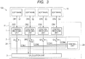
- Fig. 3 is a block diagram showing the arbitration operation in the semiconductor device 100 according to the first embodiment. For simplifying the drawing, an operating system and a bus are not shown in Fig. 3 .
- the control unit 2B closes the switching element Q2 (causes the switching element Q2 to be on) and opens the switching elements Q1, Q3, and Q4 (causes the switching elements Q1, Q3, and Q4 to be off).
- the control receiving unit CR2 and the calculation unit 3 are coupled to each other.
- the control receiving unit CR2 outputs the held operation request OR2 to the calculation unit 3.
- the calculation unit 3 performs processing according to the received operation request OR2.
- the switching elements Q1, Q3, and Q4 are physically separated from the calculation unit 3, so that the calculation unit 3 can reliably perform the processing according to the operation request OR2.
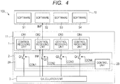
- Fig. 4 is a block diagram showing the response operation of the calculation unit 3 of the semiconductor device 100 according to the first embodiment. For simplifying the drawing, an operating system and a bus are not shown in Fig. 4 .
- the calculation unit 3 may transmit a processing completion notification and information generated as a result of the performed processing such as information indicating the load of the calculation unit 3 as response information INF.
- the arbitration of the operation requests is performed in the hardware IP, so that the CPU need not perform software processing, and thereby it is possible to reduce the load of the CPU.
- the control receiving units corresponding to the software modules executed by the CPU are provided in the hardware IP, so that the CPU can sequentially output operation requests from the software modules. As a result, it can be understood that operation requests to be transmitted are not accumulated in the CPU and the load of the CPU can be further reduced.
- the operation requests OR1 to ORn of the software modules S1 to Sn are transmitted to the control receiving units CR1 to CRn dedicatedly provided, respectively. Therefore, each operation request can reach the calculation unit 3 without interfering or intersecting with the other operation requests.
- the control receiving units exclusively and respectively corresponding to the software modules S1 to Sn from a viewpoint of securing functional safety of the software modules, it is possible to secure the functional safety of the software modules.
- each of a terrestrial digital broadcasting reproduction application and a DVD/BD (Digital Versatile Disc/Blue-ray Disc) (registered trademark) reproduction application independently issues an operation request to a video/audio decoder IP (Intellectual Property).
- a video/audio decoder IP Intelligent Property
- arbitration processing can be performed in the hardware IP 11 of the semiconductor device 100.
- each of an application for transmitting moving image data to TV through WiFi and an application for reproducing a moving image on a panel of the smartphone independently issues an operation request to a video/audio codec IP (Intellectual Property).
- a video/audio codec IP Intelligent Property
- the control receiving units the number of which is the same as that of the software modules to be executed, are provided.
- the greater the number of the software modules the greater the number of the control receiving units to be provided, so that it causes the semiconductor device (that is, SoC) to be large.
- SoC semiconductor device
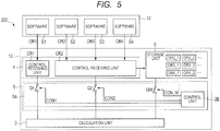
- Fig. 5 is a block diagram schematically showing a configuration of a semiconductor device 200 according to the second embodiment.
- a hardware IP 12 of the semiconductor device 200 corresponds to the hardware IP 11 of the semiconductor device 100 according to the first embodiment.
- the hardware IP 12 has a configuration in which the storage unit 1 of the hardware IP 11 according to the first embodiment is replaced by a storage unit 4, the arbitration unit 2 is replaced by an arbitration unit 5, and further a storage unit 6 is added.
- the storage units 1 and 4 are also referred to as a first storage unit and the storage unit 6 is also referred to as a second storage unit.
- the other configuration of the semiconductor device 200 is the same as that of the semiconductor device 1, so that the description thereof will be omitted.
- the storage unit 4 is provided with control receiving units CR1 to CRm (m is an integer that satisfies 2 ⁇ m ⁇ n) that receive operation requests transmitted from the software modules S1 to Sn to be executed.
- control receiving units CR1 to CRm m is an integer that satisfies 2 ⁇ m ⁇ n
- the number of the control receiving units is smaller than that of the software modules.
- Each of the control receiving units CR1 to CRm receives an operation request from a corresponding software module and transmits information in the control receiving unit to the corresponding software module.
- the storage unit 6 may be various types of storage device such as an external memory (DRAM: Dynamic Random Access Memory) and a cache memory.
- the storage unit 6 sequentially stores operation requests transmitted from a part or all of the control receiving units CR1 to CRm and transits a stored operation request to the control unit 2B according to a request of the control unit 2B.
- the arbitration unit 5 has a configuration in which the switching circuit 2A of the arbitration unit 2 is replaced by a switching circuit 5A (also referred to as the first switching circuit).
- the switching circuit 5A has a configuration in which the switching elements Q3 and Q4 of the switching circuit 2A are deleted and a switching element QM is newly added.
- the switching element QM may be formed by a transistor such as a MOSFET (Metal-Oxide-Semiconductor Field-Effect Transistor) and a bipolar transistor.
- MOSFET Metal-Oxide-Semiconductor Field-Effect Transistor
- the control unit 2B controls open/close (on/off) of the switching elements Q1, Q2, and QM by control signals CON1, CON2, and CON_M.
- the control unit 2B controls open/close (on/off) of the switching element QM by applying a gate voltage (that is, the control signal CON_M) to the gate (control terminal) of the switching elements QM.
- the control unit 2B controls the switching elements Q1, Q2, and QM so that only one of the switching elements Q1, Q2, and QM is closed (becomes on).
- the storage unit 6 transmits a stored operation request to the control unit 2B according to a request of the control unit 2B.
- the control unit 2B performs control so that only one of the switching elements Q1 and Q2 is closed (becomes on).
- the storage unit 4 transmits the operation request to a register corresponding to the operation request to be outputted.
- the control unit 2B closes (turns on) a switching element (the witching element Q1 or Q2) coupled to the register that has received the operation request, the operation request can be transmitted from the register to the calculation unit 3.
- the software modules S1 to S4 transmit operation requests OR1 to OR4, respectively, at the same time or at close timings.
- the control receiving unit CR1 receives only the operation request OR1 from the software module S1.
- the control receiving unit CR1 and the software module S1 have one-to-one correspondence relationship.
- the control receiving unit CR2 receives the operation requests OR2 to OR4 from the software modules S2 to S4.
- the control receiving unit CR2 transmits the received operation requests to the storage unit 6.
- the transmitted operation requests are stored in the storage unit 4.
- Fig. 5 shows the operation requests stored in the storage unit 6 as OR2_1, OR2_2, ..., OR3_1, OR3_2, ..., OR4_1, OR4_2, ).
- the operation requests stored in the storage unit may be labeled according to a software module of a transmission source (priority may be set between the software modules) or may be labeled according to an order of transmission (priority may be set in order from the operation request transmitted earliest to the operation request transmitted last).
- the control receiving unit CR2 stores the received operation requests in the storage unit 6, and thereafter, deletes the stored operation requests from the control receiving unit CR2 and returns to a state in which the control receiving unit CR2 can receive the other operation requests transmitted from the software modules.
- control receiving unit CR2 can reduce time for holding the operation requests and receive operation requests transmitted continuously from a plurality of software modules without delay. As a result, it is possible to avoid waiting for transmission of operation requests of the software modules S2 to S4, so that it is possible to improve utilization efficiency of the CPU.
- the arbitration unit 5 determines which operation request of the operation requests stored in the control receiving units CR1 and CR2 and the storage unit 6 is to be transferred to the calculation unit 3 according to a set arbitration method. For example, when using round robin as the arbitration method, the arbitration unit 5 selects the transmission source of the operation request by sequentially referring to the control receiving unit CR1, the control receiving unit CR2, and the storage unit 6. When referring to the storage unit 6, the arbitration unit 5 refers to an operation request attached with a label of highest priority.
- the arbitration unit 5 performs a control operation in the same manner as in the first embodiment so that the operation request from the selected transmission source is transmitted to the calculation unit 3.
- control receiving unit CR1 may sequentially store the received operation requests in the storage unit 6. Thereby, the control receiving unit CR1 can reduce time for holding the operation requests and receive operation requests without delay even when the operation requests are continuously transmitted from the software module S1. As a result, it is possible to avoid waiting for transmission of operation requests of the software module S1, so that it is possible to improve utilization efficiency of the CPU.
- control receiving unit CR1 corresponds to only the software module S1. However, the control receiving unit CR1 may correspond to a plurality of software modules.
- control receiving units receives operation requests transmitted from a plurality of software modules and thereby it is possible to reduce the number of control receiving units. Thereby, it is advantageous to be able to reduce the size of the semiconductor device.
- the control receiving unit CR1 corresponds to only the software module S1.
- the software module S1 is required to secure high functional safety, it is desirable to assign the dedicated control receiving unit CR1 to the software module S1.
- any other software module does not relate to the information transmission path between the software module S1 and the calculation unit 3. Therefore, it is possible to preliminarily avoid a situation in which the operation request from the software module S1 is obstructed or interrupted by an operation request from a software module other than the software module S1. As a result, it is possible to reliably transmit the operation request from the software module S1, which is highly required to hold functional safety, to the calculation unit 3.
- a semiconductor device according to a third embodiment will be described.
- a semiconductor device 300 according to the third embodiment is a modified example of the semiconductor device 100 according to the first embodiment.
- the semiconductor device 300 controls the operation of the arbitration unit based on information transmitted from the calculation unit 3.
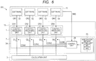
- Fig. 6 is a block diagram schematically showing a configuration of the semiconductor device 300 according to the third embodiment. For simplifying the drawing, an operating system and a bus are not shown in Fig. 6 .
- a hardware IP 13 of the semiconductor device 300 corresponds to the hardware IP 11 of the semiconductor device 100 according to the first embodiment.
- the hardware IP 13 has a configuration in which the arbitration unit 2 of the hardware IP 11 according to the first embodiment is replaced by an arbitration unit 7.
- the arbitration unit 7 has a configuration in which an arbitration method setting unit 7C is added to the arbitration unit 2 according to the first embodiment.
- the arbitration method setting unit 7C stores a plurality of arbitration methods (AR1, AR2, and so on in Fig. 6 ) which are used by the control unit 2B to arbitrate the operation requests.
- the arbitration methods stored in the arbitration method setting unit 7C may be given in advance or may be rewritable from outside the arbitration method setting unit 7C.
- the control unit 2B reads an arbitration method specified by an order ORD from the CPU 10 (CPU 10_1 to CPU_N) and performs arbitration of the operation requests according to the specific read arbitration method.
- the semiconductor device 300 performs the arbitration operation of the operation requests in the same manner as the semiconductor device 100 according to the first embodiment.
- the calculation unit 3 that receives an operation request performs processing according to the operation request and transmits information generated as a result of the processing (for example, a load factor of the calculation unit 3 and a processing completion notification of the calculation unit 3) to a software module which is the transmission source of the operation request (that is, the CPU section 10) in the same manner as in the first embodiment.
- the software module S2 is the transmission source of the operation request.
- the software module S2 specifies an arbitration method to be used by the control unit 2B based on the information received from the calculation unit 3. For example, when the software module S2 receives information indicating the load factor of the calculation unit 3, if the load factor is smaller than a predetermined value, the round robin is used as the arbitration method, and if the load factor is greater than the predetermined value, a labeled control receiving unit may be selected assuming that a real-time request is high.
- an operation request from another software module may be executed by stopping the processing of the calculation unit 3 and issuing an instruction from the CPU to the control unit.
- the operation in the hardware IP is reliably completed within a predetermined period of time, so that it is possible to perform more accurate arbitration operation
- the processing being executed by the calculation unit 3 may be stopped and the operation request from the specific software module may be executed.
- the calculation unit 3 autonomously performs reset and thereafter notifies the completion of the reset to the control receiving unit that has transmitted the operation request related to the stopped processing. Thereafter, the operation request from the specific software module is executed.
- the control receiving unit can set a period of time from when the processing being executed by the calculation unit 3 is stopped to when the operation request from the specific software module is started. Thereby, it is possible to preferentially execute a specific software module when the specific software module is required to secure high functional safety, so that it is possible to perform a more detailed arbitration operation.
- the calculation unit 3 may set a period of time from when the processing being executed by the calculation unit 3 is stopped to when the next operation becomes able to be started in the control receiving unit. In this case, by transmitting the set information to the software module, the software module can know the state of the calculation unit 3. Thereby, the software module can perform more flexible control of the hardware IP by changing a processing order of itself and an arbitration method that is set in the arbitration method setting unit.
- a semiconductor device 400 according to the fourth embodiment is a modified example of the semiconductor device 100 according to the first embodiment.
- the semiconductor device 400 has a configuration for securing functional safety of a specific software module.
- Fig. 7 is a block diagram schematically showing a configuration of the semiconductor device 400 according to the fourth embodiment. For simplifying the drawing, an operating system and a bus are not shown in Fig. 7 .
- a hardware IP 14 of the semiconductor device 400 corresponds to the hardware IP 11 of the semiconductor device 100 according to the first embodiment.
- the hardware IP 14 has a configuration in which a switching circuit 8 (also referred to as a second switching circuit) is added to the hardware IP 11 according to the first embodiment.
- the switching circuit 8 has switching elements SW1 to SWn and is inserted between the storage unit 1 and the arbitration unit 2.
- the switching elements SW1 to SWn are respectively inserted between the control receiving units CR1 to CRn and the arbitration unit 2.
- the switching elements SW1 to SWn are opened and closed (turned on and off) by control signal (s) from one or a plurality of control receiving units.
- a control receiving unit corresponding to a software module where functional safety is required to be secured is set as a control receiving unit that controls open/close (on/off) of the switching elements SW1 to SWn.
- the control receiving unit CR1 controls open/close (on/off) of the switching elements SW1 to SW4 of the switching circuit 8. In normal times, as shown in Fig. 7 , the switching elements SW1 to SW4 are closed so that an operation request can be transmitted from each control receiving unit.
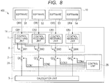
- FIG. 8 is a block diagram showing an operation of the semiconductor device 400 according to the fourth embodiment. For simplifying the drawing, an operating system and a bus are not shown in Fig. 8 . As shown in Fig. 8 , an operation request from the control receiving units CR2 to CR4 other than the control receiving unit CR1 is prevented from being transmitted. In a state shown in Fig. 8 , the operation request OR1 is transmitted to the calculation unit 3, so that the switching element Q1 is closed. Thereby, the operation request OR1 from the software module S1 is reliably and preferentially executed without being interrupted by another operation request, so that it is possible to satisfy functional safety request for the software module S1.
- the switching circuit 8 may further include four switching elements (second switching elements) respectively inserted between the software modules S1 to S4 and the control receiving units CR1 to CR4.
- the control receiving unit CR1 may close one of the four switching elements, which is coupled to the control receiving unit CR1, and open the other switching elements which are coupled to the control receiving units CR2 to CR4.
- the present invention is not limited to the above embodiments and may be appropriately modified without departing from the scope of the invention.
- specific examples in which four software modules operate are described.
- the semiconductor device 300 according to the third embodiment described above in the same manner as in the semiconductor device 200 according to the second embodiment, it is needless to say that a configuration can be formed in which the number of the control receiving units is smaller than the number of the software modules and the storage unit 6 is provided to sequentially store the operation requests from the control receiving units.
- the semiconductor device 400 according to the fourth embodiment described above in the same manner as in the semiconductor device 200 according to the second embodiment, it is needless to say that a configuration may be formed in which the number of the control receiving units is smaller than the number of the software modules and the storage unit 6 is provided to sequentially store the operation requests from the control receiving units. Also in the semiconductor device 400 according to the fourth embodiment described above, in the same manner as in the semiconductor device 300 according to the third embodiment, it is needless to say that a configuration may be formed in which the arbitration method setting unit is provided to change the arbitration method to be used by the control unit 2B based on the information transmitted from the calculation unit 3.
- a configuration may be formed in which the number of the control receiving units is smaller than the number of the software modules and the storage unit 6 is provided to sequentially store the operation requests from the control receiving units in the same manner as in the semiconductor device 200 according to the second embodiment and the arbitration method setting unit is provided to change the arbitration method to be used by the control unit 2B based on the information transmitted from the calculation unit 3 in the same manner as in the semiconductor device 300 according to the third embodiment.
- the program described above is stored in various types of non-transitory computer readable medium and can be supplied to a computer.
- the non-transitory computer readable media include various types of tangible storage media. Examples of the non-transitory computer readable medium include a magnetic recording medium (for example, flexible disk, magnetic tape, and hard disk drive), a magneto-optical recording medium (for example, magneto-optical disk), a CD-ROM (Read Only Memory), a CD-R, a CD-R/W, a semiconductor memory (for example, mask ROM, PROM (Programmable ROM), EPROM (Erasable PROM), flash ROM, RAM (Random Access Memory)).
- the program may be supplied to a computer by various types of transitory computer readable medium.
- Examples of the non-transitory computer readable medium include an electrical signal, an optical signal, and an electromagnetic wave.
- the non-transitory computer readable medium can supply the program to a computer through a wired communication path such as an electrical wire and an optical fiber or a wireless communication path.
- the switching circuits are formed by a single switching element realized by MOSFET or the like.
- MOSFET MOSFET
- the switching circuits may have another configuration.
- the number of the switching elements provided in the switching circuit is not limited to that in the examples of the embodiments described above, and elements other than the switching elements may be included.
- the switching circuit may be formed by using one or a plurality of logical circuits.
Landscapes
- Engineering & Computer Science (AREA)
- Theoretical Computer Science (AREA)
- Physics & Mathematics (AREA)
- General Engineering & Computer Science (AREA)
- General Physics & Mathematics (AREA)
- Computer Hardware Design (AREA)
- Software Systems (AREA)
- Mathematical Physics (AREA)
- Computer Networks & Wireless Communication (AREA)
- Microelectronics & Electronic Packaging (AREA)
- Computing Systems (AREA)
- Microcomputers (AREA)
- Advance Control (AREA)
- Logic Circuits (AREA)
Abstract
Description
- The disclosure of Japanese Patent Application No.
2015-235387 filed on December 2, 2015 - The present invention relates to a semiconductor device and a control method of a semiconductor device.
- An SoC (System-on-a-chip) is a semiconductor chip in which a plurality of functions are integrated. The SoC includes a plurality of CPUs. In the SoC, a plurality of applications are performed at the same time. In recent years, upsizing of the SoC is advanced by performance improvement of a system on which the SoC is mounted.
- In the SoC, an operation request to a hardware IP (Intellectual Property) of the semiconductor chip may be received from a plurality of applications at the same time. The hardware IP is partial circuit information collected for each function to form the semiconductor chip and is information implemented by hardware. In this case, it is necessary to arbitrate operation requests conflicting with each other in order to avoid malfunction and the like.
- As a method of such arbitration, a method that arbitrates operation requests conflicting with each other by software processing is proposed (Japanese Unexamined Patent Application Publication No.
2010-140290 - Another method that arbitrates operation requests conflicting with each other by software processing is also proposed (Japanese Unexamined Patent Application Publication No.
2011-232956 - However, the inventors found that the arbitration methods as described above have a problem described below. In the arbitration methods described above, to acquire a privilege to use a shared resource, it is necessary to perform arbitration processing by communication between CPUs and communication between an operating system and an application (software). Therefore, a response of the arbitration processing depends on CPU throughput, the operating system, and the application (software). As the speed of the hardware IP of semiconductor device increases, the response frequency of software increases and a load applied to CPU also increases. Therefore, it is difficult to realize response performance of the arbitration processing by software.
- Other objects and novel features will become apparent from the description of the present specification and the accompanying drawings.
- According to an embodiment, a semiconductor device includes a CPU section in which a plurality of software modules are executed and a hardware IP. The hardware IP includes a first storage unit including a plurality of control receiving units that receive operation requests of the plurality of software modules, a calculation unit that performs processing based on an operation request, and an arbitration unit that controls information transmission between the plurality of control receiving units and the calculation unit so that the calculation unit receives only one operation request.
- According to an embodiment, in a semiconductor device that includes a CPU section in which a plurality of software modules are executed and a hardware IP, a control method of the semiconductor device controls information transmission between a plurality of control receiving units included in a first storage unit of the hardware IP and a calculation unit of the hardware IP so that the calculation unit receives only an operation request from any one of the plurality of control receiving units that receive operation requests of the plurality of software modules.
- According to an embodiment, it is possible to reduce a load of CPU required for arbitration when using a shared resource in a semiconductor device.
-
-
Fig. 1 is a block diagram schematically showing a hardware configuration of a semiconductor device according to a first embodiment. -
Fig. 2 is a block diagram schematically showing a configuration of the semiconductor device according to the first embodiment. -
Fig. 3 is a block diagram showing an arbitration operation in the semiconductor device according to the first embodiment. -
Fig. 4 is a block diagram showing a response operation of a calculation unit of the semiconductor device according to the first embodiment. -
Fig. 5 is a block diagram schematically showing a configuration of a semiconductor device according to a second embodiment. -
Fig. 6 is a block diagram schematically showing a configuration of a semiconductor device according to a third embodiment. -
Fig. 7 is a block diagram schematically showing a configuration of a semiconductor device according to a fourth embodiment. -
Fig. 8 is a block diagram showing an operation of the semiconductor device according to the fourth embodiment. - Hereinafter, embodiments of the present invention will be described with reference to the drawings. In each drawing, the same components are denoted by the same reference symbols and redundant description is omitted as appropriate.
- A
semiconductor device 100 according to a first embodiment will be described.Fig. 1 is a block diagram schematically showing a hardware configuration of thesemiconductor device 100 according to the first embodiment. Thesemiconductor device 100 includes CPUs (Central Processing Units) 10_1 to 10_N (N is an integer greater than or equal to 2) and a hardware IP (Intellectual Property) 11. The CPUs 10_1 to 10_N and thehardware IP 11 can transmit and receive information to and from each other through abus 20. - The CPUs 10_1 to 10_N are configured to be able to execute a predetermined operating system. The operating system may be executed by any one of the CPUs 10_1 to 10_N or may be executed by a plurality of CPUs. This example shows that operating systems OS_1 to OS_N are executed by the CPUs 10_1 to 10_N, respectively. Hereinafter, for simplifying the description, the CPUs 10_1 to 10_N are also referred to as a
CPU section 10. - In each operating system, one or a plurality of software modules are executed. Here, it is assumed that software modules S1 to Sn are executed by the CPUs 10_1 to 10_N (that is, operating systems OS_1 to OS_N), respectively.
- The
hardware IP 11 includes astorage unit 1, anarbitration unit 2, and acalculation unit 3. Thestorage unit 1 is provided with control receiving units CR1 to CRn respectively corresponding to the software modules S1 to Sn to be executed. Each of the control receiving units CR1 to CRn includes, for example, an independent register. In other words, the control receiving units CR1 to CRn have one-to-one correspondence relationship with the software modules S1 to Sn, respectively, without overlapping. In other words, a control receiving units CRi (i is an integer that satisfies 1 ≤ i ≤ n) receives an operation request from only a software module Si and transmits information in the control receiving units CRi to only the software module Si. - The
arbitration unit 2 controls exchange of information (information transmission) between the control receiving units CR1 to CRn and thecalculation unit 3 so that only an operation request from any one of the control receiving units CR1 to CRn is transmitted to thecalculation unit 3. Further, thearbitration unit 2 controls exchange of information (information transmission) between the control receiving units CR1 to CRn and thecalculation unit 3 so that information (response information) generated as a result of an operation, which is performed by thecalculation unit 3 according to the received operation request, is transmitted to the control receiving unit that has outputted the operation request. - The
calculation unit 3 is a shared resource shared by the CPUs 10_1 to 10_N. Thecalculation unit 3 performs processing according to an operation request from software. - Hereinafter, an arbitration operation of operation requests in the
semiconductor device 100 will be specifically described. Here, for simplifying the description, an example will be described in which four software modules S1 to S4 operate and four control receiving units CR1 to CR4 corresponding to the four software modules S1 to S4 are provided in thesemiconductor device 100.Fig. 2 is a block diagram schematically showing a configuration of thesemiconductor device 100 according to the first embodiment. For simplifying the drawing, an operating system and a bus are not shown inFig. 2 . - First, the software modules S1 to S4 transmit operation requests OR1 to OR4 to the control receiving units CR1 to CR4, respectively, at the same time or at close timings. The control receiving units CR1 to CR4 hold the received operation requests OR1 to OR4, respectively.
- The
arbitration unit 2 selects an operation request to be transferred to thecalculation unit 3 from among the operation requests held by the control receiving units CR1 to CR4 according to a set arbitration method. For example, thearbitration unit 2 can apply an arbitration method such as round robin and LRU (Least Recently Used) as the arbitration method. Thearbitration unit 2 may randomly select a control receiving unit. - The
arbitration unit 2 operates so that an operation request held by the selected control receiving unit is transmitted to thecalculation unit 3 according to the set arbitration method. - As shown in
Fig. 2 , thearbitration unit 2 includes aswitching circuit 2A (also referred to as a first switching circuit) and acontrol unit 2B. Theswitching circuit 2A includes switching elements Q1 to Q4. The switching element Q1 may be formed by a transistor such as a MOSFET (Metal-Oxide-Semiconductor Field-Effect Transistor) and a bipolar transistor. In this example, the switching elements Q1 to Q4 are inserted between the control receiving units CR1 to CR4 and thecalculation unit 3, respectively. - The
control unit 2B controls open/close (on/off) of the switching elements Q1 to Q4 by control signals CON1 to CON4. For example, when the switching elements Q1 to Q4 are MOSFETs, thecontrol unit 2B controls open/close (on/off) of the switching elements Q1 to Q4 by applying gate voltages (that is, control signals CON1 to CON4) to gates (control terminals) of the switching elements Q1 to Q4. In the present embodiment, thecontrol unit 2B controls the switching elements Q1 to Q4 so that only one of the switching elements Q1 to Q4 is closed (becomes on). - The
control unit 2B selects a control receiving unit to which an operation request is transmitted according to the set arbitration method described above. Here, a case will be described in which the control receiving unit CR2 is selected as the control receiving unit to which an operation request is transmitted.Fig. 3 is a block diagram showing the arbitration operation in thesemiconductor device 100 according to the first embodiment. For simplifying the drawing, an operating system and a bus are not shown inFig. 3 . In this case, as shown inFig. 3 , thecontrol unit 2B closes the switching element Q2 (causes the switching element Q2 to be on) and opens the switching elements Q1, Q3, and Q4 (causes the switching elements Q1, Q3, and Q4 to be off). Thereby, the control receiving unit CR2 and thecalculation unit 3 are coupled to each other. - In this state, the control receiving unit CR2 outputs the held operation request OR2 to the
calculation unit 3. Thecalculation unit 3 performs processing according to the received operation request OR2. In this case, the switching elements Q1, Q3, and Q4 are physically separated from thecalculation unit 3, so that thecalculation unit 3 can reliably perform the processing according to the operation request OR2. As described above, according to the present configuration, it is possible to arbitrate the operation requests from the control receiving units CR1 to CR4 and transmit only any one of the operation requests to thecalculation unit 3. - After the
calculation unit 3 performs the processing according to the received operation request OR2, thecalculation unit 3 may transmit information generated as a result of the performed processing to the control receiving unit CR2 that has transmitted the operation request OR2 (hereinafter, this is referred to as a response operation of the calculation unit).Fig. 4 is a block diagram showing the response operation of thecalculation unit 3 of thesemiconductor device 100 according to the first embodiment. For simplifying the drawing, an operating system and a bus are not shown inFig. 4 . For example, in the response operation, thecalculation unit 3 may transmit a processing completion notification and information generated as a result of the performed processing such as information indicating the load of thecalculation unit 3 as response information INF. - As described above, according to the present configuration, the arbitration of the operation requests is performed in the hardware IP, so that the CPU need not perform software processing, and thereby it is possible to reduce the load of the CPU. The control receiving units corresponding to the software modules executed by the CPU are provided in the hardware IP, so that the CPU can sequentially output operation requests from the software modules. As a result, it can be understood that operation requests to be transmitted are not accumulated in the CPU and the load of the CPU can be further reduced.
- Further, the present configuration is advantageous from a viewpoint of functional safety. Hereinafter, the reason of the above will be described. The operation requests OR1 to ORn of the software modules S1 to Sn are transmitted to the control receiving units CR1 to CRn dedicatedly provided, respectively. Therefore, each operation request can reach the
calculation unit 3 without interfering or intersecting with the other operation requests. Thus, by providing the control receiving units exclusively and respectively corresponding to the software modules S1 to Sn from a viewpoint of securing functional safety of the software modules, it is possible to secure the functional safety of the software modules. - It is possible to mount the
semiconductor device 100 described above in an in-vehicle terminal such as a car navigation system. For example, in the car navigation system, each of a terrestrial digital broadcasting reproduction application and a DVD/BD (Digital Versatile Disc/Blue-ray Disc) (registered trademark) reproduction application independently issues an operation request to a video/audio decoder IP (Intellectual Property). At this time, even if an operation request is issued from both the applications, arbitration processing can be performed in thehardware IP 11 of thesemiconductor device 100. When assuming a case in which driving control is performed by using a driving support function of a car navigation system, a high functional safety is required for applications related to the driving control from a view point of securing safety of vehicle driving. Also in this case, as described above, it is possible to realize high functional safety in thesemiconductor device 100. - Further, it is possible to mount the
semiconductor device 100 described above in a mobile terminal such as a smartphone. For example, in the smartphone, each of an application for transmitting moving image data to TV through WiFi and an application for reproducing a moving image on a panel of the smartphone independently issues an operation request to a video/audio codec IP (Intellectual Property). At this time, even if an operation request is issued from both the applications, arbitration processing can be performed in thehardware IP 11 of thesemiconductor device 100. - In the first embodiment described above, a semiconductor device is described in which the control receiving units, the number of which is the same as that of the software modules to be executed, are provided. However, in the configuration described above, the greater the number of the software modules, the greater the number of the control receiving units to be provided, so that it causes the semiconductor device (that is, SoC) to be large. On the other hand, in the present embodiment, as a modified example of the
semiconductor device 100 according to the first embodiment, a semiconductor device that performs the arbitration processing in the hardware IP while suppressing the number of the control receiving units will be described. -
Fig. 5 is a block diagram schematically showing a configuration of asemiconductor device 200 according to the second embodiment. For simplifying the drawing, an operating system and a bus are not shown inFig. 5 . Ahardware IP 12 of thesemiconductor device 200 corresponds to thehardware IP 11 of thesemiconductor device 100 according to the first embodiment. Thehardware IP 12 has a configuration in which thestorage unit 1 of thehardware IP 11 according to the first embodiment is replaced by astorage unit 4, thearbitration unit 2 is replaced by anarbitration unit 5, and further astorage unit 6 is added. For clarity of the description, thestorage units storage unit 6 is also referred to as a second storage unit. The other configuration of thesemiconductor device 200 is the same as that of thesemiconductor device 1, so that the description thereof will be omitted. - The
storage unit 4 is provided with control receiving units CR1 to CRm (m is an integer that satisfies 2 < m < n) that receive operation requests transmitted from the software modules S1 to Sn to be executed. In other words, in the present embodiment, although a plurality of control receiving units are provided, the number of the control receiving units is smaller than that of the software modules. Each of the control receiving units CR1 to CRm receives an operation request from a corresponding software module and transmits information in the control receiving unit to the corresponding software module. - The
storage unit 6 may be various types of storage device such as an external memory (DRAM: Dynamic Random Access Memory) and a cache memory. Thestorage unit 6 sequentially stores operation requests transmitted from a part or all of the control receiving units CR1 to CRm and transits a stored operation request to thecontrol unit 2B according to a request of thecontrol unit 2B. - The
arbitration unit 5 has a configuration in which theswitching circuit 2A of thearbitration unit 2 is replaced by aswitching circuit 5A (also referred to as the first switching circuit). Theswitching circuit 5A has a configuration in which the switching elements Q3 and Q4 of theswitching circuit 2A are deleted and a switching element QM is newly added. The switching element QM may be formed by a transistor such as a MOSFET (Metal-Oxide-Semiconductor Field-Effect Transistor) and a bipolar transistor. The switching element QM is inserted between thestorage unit 6 and thecalculation unit 3. - The
control unit 2B controls open/close (on/off) of the switching elements Q1, Q2, and QM by control signals CON1, CON2, and CON_M. When the switching element QM is MOSFET, thecontrol unit 2B controls open/close (on/off) of the switching element QM by applying a gate voltage (that is, the control signal CON_M) to the gate (control terminal) of the switching elements QM. In the present embodiment, thecontrol unit 2B controls the switching elements Q1, Q2, and QM so that only one of the switching elements Q1, Q2, and QM is closed (becomes on). - A configuration is possible in which the switching element QM described above is not used. In this case, the
storage unit 6 transmits a stored operation request to thecontrol unit 2B according to a request of thecontrol unit 2B. Thecontrol unit 2B performs control so that only one of the switching elements Q1 and Q2 is closed (becomes on). When thestorage unit 4 outputs the stored operation request, thestorage unit 4 transmits the operation request to a register corresponding to the operation request to be outputted. When thecontrol unit 2B closes (turns on) a switching element (the witching element Q1 or Q2) coupled to the register that has received the operation request, the operation request can be transmitted from the register to thecalculation unit 3. - Hereinafter, an operation of the
semiconductor device 200 will be described. Here, for simplifying the description, an example will be described in which four software modules S1 to S4 operate and two control receiving units CR1 and CR2 are provided in thesemiconductor device 200. - First, the software modules S1 to S4 transmit operation requests OR1 to OR4, respectively, at the same time or at close timings. In this example, the control receiving unit CR1 receives only the operation request OR1 from the software module S1. In other words, the control receiving unit CR1 and the software module S1 have one-to-one correspondence relationship. On the other hand, the control receiving unit CR2 receives the operation requests OR2 to OR4 from the software modules S2 to S4. Then, the control receiving unit CR2 transmits the received operation requests to the
storage unit 6. The transmitted operation requests are stored in thestorage unit 4.Fig. 5 shows the operation requests stored in thestorage unit 6 as OR2_1, OR2_2, ..., OR3_1, OR3_2, ..., OR4_1, OR4_2, ...). For example, the operation requests stored in the storage unit may be labeled according to a software module of a transmission source (priority may be set between the software modules) or may be labeled according to an order of transmission (priority may be set in order from the operation request transmitted earliest to the operation request transmitted last). - The control receiving unit CR2 stores the received operation requests in the
storage unit 6, and thereafter, deletes the stored operation requests from the control receiving unit CR2 and returns to a state in which the control receiving unit CR2 can receive the other operation requests transmitted from the software modules. - Thereby, the control receiving unit CR2 can reduce time for holding the operation requests and receive operation requests transmitted continuously from a plurality of software modules without delay. As a result, it is possible to avoid waiting for transmission of operation requests of the software modules S2 to S4, so that it is possible to improve utilization efficiency of the CPU.
- The
arbitration unit 5 determines which operation request of the operation requests stored in the control receiving units CR1 and CR2 and thestorage unit 6 is to be transferred to thecalculation unit 3 according to a set arbitration method. For example, when using round robin as the arbitration method, thearbitration unit 5 selects the transmission source of the operation request by sequentially referring to the control receiving unit CR1, the control receiving unit CR2, and thestorage unit 6. When referring to thestorage unit 6, thearbitration unit 5 refers to an operation request attached with a label of highest priority. - The
arbitration unit 5 performs a control operation in the same manner as in the first embodiment so that the operation request from the selected transmission source is transmitted to thecalculation unit 3. - In the above description, the control receiving unit CR1 may sequentially store the received operation requests in the
storage unit 6. Thereby, the control receiving unit CR1 can reduce time for holding the operation requests and receive operation requests without delay even when the operation requests are continuously transmitted from the software module S1. As a result, it is possible to avoid waiting for transmission of operation requests of the software module S1, so that it is possible to improve utilization efficiency of the CPU. - In the above description, the control receiving unit CR1 corresponds to only the software module S1. However, the control receiving unit CR1 may correspond to a plurality of software modules.
- As described above, according to the present configuration, a part or all of the control receiving units receives operation requests transmitted from a plurality of software modules and thereby it is possible to reduce the number of control receiving units. Thereby, it is advantageous to be able to reduce the size of the semiconductor device.
- In the above description, the control receiving unit CR1 corresponds to only the software module S1. When one control receiving unit and one software module correspond one-to-one to each other, there is merit from a viewpoint of functional safety. In other words, when the software module S1 is required to secure high functional safety, it is desirable to assign the dedicated control receiving unit CR1 to the software module S1. Thereby, any other software module does not relate to the information transmission path between the software module S1 and the
calculation unit 3. Therefore, it is possible to preliminarily avoid a situation in which the operation request from the software module S1 is obstructed or interrupted by an operation request from a software module other than the software module S1. As a result, it is possible to reliably transmit the operation request from the software module S1, which is highly required to hold functional safety, to thecalculation unit 3. - A semiconductor device according to a third embodiment will be described. A
semiconductor device 300 according to the third embodiment is a modified example of thesemiconductor device 100 according to the first embodiment. Thesemiconductor device 300 controls the operation of the arbitration unit based on information transmitted from thecalculation unit 3.Fig. 6 is a block diagram schematically showing a configuration of thesemiconductor device 300 according to the third embodiment. For simplifying the drawing, an operating system and a bus are not shown inFig. 6 . Ahardware IP 13 of thesemiconductor device 300 corresponds to thehardware IP 11 of thesemiconductor device 100 according to the first embodiment. Thehardware IP 13 has a configuration in which thearbitration unit 2 of thehardware IP 11 according to the first embodiment is replaced by anarbitration unit 7. - The
arbitration unit 7 has a configuration in which an arbitrationmethod setting unit 7C is added to thearbitration unit 2 according to the first embodiment. The arbitrationmethod setting unit 7C stores a plurality of arbitration methods (AR1, AR2, and so on inFig. 6 ) which are used by thecontrol unit 2B to arbitrate the operation requests. The arbitration methods stored in the arbitrationmethod setting unit 7C may be given in advance or may be rewritable from outside the arbitrationmethod setting unit 7C. For example, thecontrol unit 2B reads an arbitration method specified by an order ORD from the CPU 10 (CPU 10_1 to CPU_N) and performs arbitration of the operation requests according to the specific read arbitration method. - Hereinafter, the arbitration operation of the
semiconductor device 300 will be specifically described. Thesemiconductor device 300 performs the arbitration operation of the operation requests in the same manner as thesemiconductor device 100 according to the first embodiment. Thecalculation unit 3 that receives an operation request performs processing according to the operation request and transmits information generated as a result of the processing (for example, a load factor of thecalculation unit 3 and a processing completion notification of the calculation unit 3) to a software module which is the transmission source of the operation request (that is, the CPU section 10) in the same manner as in the first embodiment. - In the description of this example, it is assumed the software module S2 is the transmission source of the operation request. In this case, the software module S2 specifies an arbitration method to be used by the
control unit 2B based on the information received from thecalculation unit 3. For example, when the software module S2 receives information indicating the load factor of thecalculation unit 3, if the load factor is smaller than a predetermined value, the round robin is used as the arbitration method, and if the load factor is greater than the predetermined value, a labeled control receiving unit may be selected assuming that a real-time request is high. - For example, when the information from the
calculation unit 3 is not transmitted to the software module of the transmission source within a predetermined period of time, an operation request from another software module may be executed by stopping the processing of thecalculation unit 3 and issuing an instruction from the CPU to the control unit. Thereby, the operation in the hardware IP is reliably completed within a predetermined period of time, so that it is possible to perform more accurate arbitration operation - For example, when an operation request from a specific software module is received by a corresponding control receiving unit, the processing being executed by the
calculation unit 3 may be stopped and the operation request from the specific software module may be executed. In this case, thecalculation unit 3 autonomously performs reset and thereafter notifies the completion of the reset to the control receiving unit that has transmitted the operation request related to the stopped processing. Thereafter, the operation request from the specific software module is executed. Further, the control receiving unit can set a period of time from when the processing being executed by thecalculation unit 3 is stopped to when the operation request from the specific software module is started. Thereby, it is possible to preferentially execute a specific software module when the specific software module is required to secure high functional safety, so that it is possible to perform a more detailed arbitration operation. - Further, the
calculation unit 3 may set a period of time from when the processing being executed by thecalculation unit 3 is stopped to when the next operation becomes able to be started in the control receiving unit. In this case, by transmitting the set information to the software module, the software module can know the state of thecalculation unit 3. Thereby, the software module can perform more flexible control of the hardware IP by changing a processing order of itself and an arbitration method that is set in the arbitration method setting unit. - As described above, it is possible to select an arbitration method suitable for a processing state of the calculation unit by using information that is fed back according to the processing result of the calculation unit. This can be realized without largely changing a hardware configuration the semiconductor device, so that it is possible to effectively use processing resources of the calculation unit.
- A semiconductor device according to a fourth embodiment will be described. A
semiconductor device 400 according to the fourth embodiment is a modified example of thesemiconductor device 100 according to the first embodiment. Thesemiconductor device 400 has a configuration for securing functional safety of a specific software module.Fig. 7 is a block diagram schematically showing a configuration of thesemiconductor device 400 according to the fourth embodiment. For simplifying the drawing, an operating system and a bus are not shown inFig. 7 . Ahardware IP 14 of thesemiconductor device 400 corresponds to thehardware IP 11 of thesemiconductor device 100 according to the first embodiment. Thehardware IP 14 has a configuration in which a switching circuit 8 (also referred to as a second switching circuit) is added to thehardware IP 11 according to the first embodiment. - The
switching circuit 8 has switching elements SW1 to SWn and is inserted between thestorage unit 1 and thearbitration unit 2. The switching elements SW1 to SWn are respectively inserted between the control receiving units CR1 to CRn and thearbitration unit 2. - The switching elements SW1 to SWn are opened and closed (turned on and off) by control signal (s) from one or a plurality of control receiving units. In the present embodiment, a control receiving unit corresponding to a software module where functional safety is required to be secured is set as a control receiving unit that controls open/close (on/off) of the switching elements SW1 to SWn.
- Hereinafter, an operation of the
semiconductor device 400 will be described. Here, in the same manner as in the first embodiment, it is assumed that there are four software modules and four control receiving units and the software module S1 corresponding to the control receiving unit CR1 is required to secure functional safety. In this case, the control receiving unit CR1 controls open/close (on/off) of the switching elements SW1 to SW4 of theswitching circuit 8. In normal times, as shown inFig. 7 , the switching elements SW1 to SW4 are closed so that an operation request can be transmitted from each control receiving unit. - In this state, when the operation request OR1 is transmitted from the software module S1 to the control receiving unit CR1, the control receiving unit CR1 opens the switching elements SW2 to SW4 at the same time as receiving the operation request OR1.
Fig. 8 is a block diagram showing an operation of thesemiconductor device 400 according to the fourth embodiment. For simplifying the drawing, an operating system and a bus are not shown inFig. 8 . As shown inFig. 8 , an operation request from the control receiving units CR2 to CR4 other than the control receiving unit CR1 is prevented from being transmitted. In a state shown inFig. 8 , the operation request OR1 is transmitted to thecalculation unit 3, so that the switching element Q1 is closed. Thereby, the operation request OR1 from the software module S1 is reliably and preferentially executed without being interrupted by another operation request, so that it is possible to satisfy functional safety request for the software module S1. - The
switching circuit 8 may further include four switching elements (second switching elements) respectively inserted between the software modules S1 to S4 and the control receiving units CR1 to CR4. At the same time as receiving the operation request OR1, the control receiving unit CR1 may close one of the four switching elements, which is coupled to the control receiving unit CR1, and open the other switching elements which are coupled to the control receiving units CR2 to CR4. - The present invention is not limited to the above embodiments and may be appropriately modified without departing from the scope of the invention. For example, in the above embodiments, for simplifying the description, specific examples in which four software modules operate are described. However, it goes without saying that it is possible to form a semiconductor device in which two, three, or five or more software modules operate and control receiving units corresponding to these software modules are provided.
- Also in the
semiconductor device 300 according to the third embodiment described above, in the same manner as in thesemiconductor device 200 according to the second embodiment, it is needless to say that a configuration can be formed in which the number of the control receiving units is smaller than the number of the software modules and thestorage unit 6 is provided to sequentially store the operation requests from the control receiving units. - Also in the
semiconductor device 400 according to the fourth embodiment described above, in the same manner as in thesemiconductor device 200 according to the second embodiment, it is needless to say that a configuration may be formed in which the number of the control receiving units is smaller than the number of the software modules and thestorage unit 6 is provided to sequentially store the operation requests from the control receiving units. Also in thesemiconductor device 400 according to the fourth embodiment described above, in the same manner as in thesemiconductor device 300 according to the third embodiment, it is needless to say that a configuration may be formed in which the arbitration method setting unit is provided to change the arbitration method to be used by thecontrol unit 2B based on the information transmitted from thecalculation unit 3. Also in thesemiconductor device 400 according to the fourth embodiment described above, it is needless to say that a configuration may be formed in which the number of the control receiving units is smaller than the number of the software modules and thestorage unit 6 is provided to sequentially store the operation requests from the control receiving units in the same manner as in thesemiconductor device 200 according to the second embodiment and the arbitration method setting unit is provided to change the arbitration method to be used by thecontrol unit 2B based on the information transmitted from thecalculation unit 3 in the same manner as in thesemiconductor device 300 according to the third embodiment. - To clarify the description, the above description and the drawings are appropriately omitted and simplified. The components shown in the drawings as functional blocks that perform various processing can be formed by a CPU, a memory, and other circuits as hardware and are realized by a program and the like loaded in a memory as software. Therefore, it should be understood by those skilled in the art that the functional blocks can be realized in various forms by only hardware, only software, or a combination of these, and the functional blocks are not limited to any one of hardware, software, and a combination of these. In each drawing, the same components are denoted by the same reference symbols and redundant description is omitted as appropriate.
- The program described above is stored in various types of non-transitory computer readable medium and can be supplied to a computer. The non-transitory computer readable media include various types of tangible storage media. Examples of the non-transitory computer readable medium include a magnetic recording medium (for example, flexible disk, magnetic tape, and hard disk drive), a magneto-optical recording medium (for example, magneto-optical disk), a CD-ROM (Read Only Memory), a CD-R, a CD-R/W, a semiconductor memory (for example, mask ROM, PROM (Programmable ROM), EPROM (Erasable PROM), flash ROM, RAM (Random Access Memory)). The program may be supplied to a computer by various types of transitory computer readable medium. Examples of the non-transitory computer readable medium include an electrical signal, an optical signal, and an electromagnetic wave. The non-transitory computer readable medium can supply the program to a computer through a wired communication path such as an electrical wire and an optical fiber or a wireless communication path.
- In the description of the above embodiments, the switching circuits (the first and the second switching circuits) are formed by a single switching element realized by MOSFET or the like. However, this is just an example. It is needless to say that if it is possible to control exchange of information between the storage units (the first and the second storage units) and the calculation unit in the same manner as in the embodiments described above, the switching circuits may have another configuration. In this case, the number of the switching elements provided in the switching circuit is not limited to that in the examples of the embodiments described above, and elements other than the switching elements may be included. Further, the switching circuit may be formed by using one or a plurality of logical circuits.
- While the invention made by the inventors has been specifically described based on the embodiments, it is needless to say that the present invention is not limited to the embodiments described above and may be variously modified without departing from the scope of the invention.
Claims (14)
- A semiconductor device comprising:a CPU section in which a plurality of software modules are executed; anda hardware IP that performs processing based on an operation request transmitted by the CPU section,wherein the hardware IP includesa first storage unit including a plurality of control receiving units that receive an operation request transmitted by each of the software modules,a calculation unit that performs processing based on an operation request transmitted from the control receiving units, andan arbitration unit that controls information transmission between the control receiving units and the calculation unit so that the calculation unit receives only an operation request from any one of the control receiving units.
- The semiconductor device according to Claim 1,wherein the arbitration unit selects a control receiving unit to be a transmission source of an operation request to be received by the calculation unit according to a set arbitration method.
- The semiconductor device according to Claim 2,wherein the arbitration unit includesa first switching circuit including a plurality of switching elements inserted between each of the control receiving units and the calculation unit in parallel, anda control unit that controls open/close of the switching elements, andwherein the arbitration unit closes a switching element coupled to the selected control receiving unit and opens switching elements coupled to the control receiving units other than the selected control receiving unit.
- The semiconductor device according to any one of Claims 1 to 3,wherein the control receiving units, the number of which is the same as that of the software modules, are provided, andwherein the control receiving units receive operation requests from different software modules, respectively.
- The semiconductor device according to any one of Claims 1 to 3, further comprising:a second storage unit configured to be able to store one or a plurality of operation requests,wherein the number of the control receiving units is smaller than the number of the software modules,wherein a part or all of the control receiving units receive operation requests from two or more software modules,wherein a control receiving unit that receives operation requests from two or more software modules stores the received operation requests sequentially in the second storage unit, andwherein the arbitration unit controls information transmission between the control receiving units and the calculation unit so that the calculation unit receives only operation requests from any one of the control receiving units and the second storage unit.
- The semiconductor device according to Claim 5,wherein a part or all of the control receiving units receive only an operation request from any one of the software modules, andwherein a control receiving unit that receives only an operation request from any one of the software modules stores the received operation request in the second storage unit.
- The semiconductor device according to Claim 5,wherein the control receiving unit that stores the received operation requests in the second storage unit deletes the stored operation requests from the control receiving unit and returns to a state in which the control receiving unit can receive other operation requests.
- The semiconductor device according to any one of Claims 1 to 7,wherein the calculation unit transmits response information generated by performing processing based on a received operation request to a software module that has transmitted the operation request through a control receiving unit that has transmitted the operation request.
- The semiconductor device according to Claim 8,wherein the arbitration unit includes an arbitration method setting unit in which a plurality of arbitration methods are stored,wherein the CPU section specifies an arbitration method to be used by the arbitration unit based on the response information, andwherein the arbitration unit acquires an arbitration method corresponding to the specification from the arbitration method setting unit.
- The semiconductor device according to any one of Claims 1 to 9, further comprising:a second switching circuit including a plurality of first switching elements inserted between each of the control receiving units other than a specific control receiving unit and the arbitration unit in parallel,wherein when the specific control receiving unit receives an operation request, the first switching elements are opened.
- The semiconductor device according to Claim 10,wherein open/close of the switching elements of the second switching circuit is controlled by the specific control receiving unit, andwherein when the specific control receiving unit receives an operation request, the specific control receiving unit opens the first switching elements.
- The semiconductor device according to Claim 10,wherein the second switching circuit further includes a plurality of second switching elements inserted between each of the control receiving units other than the specific control receiving unit and the CPU section in parallel, andwherein when the specific control receiving unit receives an operation request, the second switching elements are opened.
- The semiconductor device according to Claim 12,wherein open/close of the second switching elements is controlled by the specific control receiving unit, andwherein when the specific control receiving unit receives an operation request, the specific control receiving unit opens the second switching elements.
- A control method of a semiconductor device that includes a CPU section in which a plurality of software modules are executed and a hardware IP that performs processing based on an operation request transmitted by the CPU section, the control method comprising the step of:controlling information transmission between a plurality of control receiving units included in a first storage unit of the hardware IP and a calculation unit of the hardware IP so that the calculation unit receives only an operation request from any one of the control receiving units that receive an operation request transmitted by each of the software modules.
Applications Claiming Priority (1)
| Application Number | Priority Date | Filing Date | Title |
|---|---|---|---|
| JP2015235387A JP6608688B2 (en) | 2015-12-02 | 2015-12-02 | Semiconductor device |
Publications (2)
| Publication Number | Publication Date |
|---|---|
| EP3176702A1 true EP3176702A1 (en) | 2017-06-07 |
| EP3176702B1 EP3176702B1 (en) | 2020-12-09 |
Family
ID=57394324
Family Applications (1)
| Application Number | Title | Priority Date | Filing Date |
|---|---|---|---|
| EP16194438.4A Active EP3176702B1 (en) | 2015-12-02 | 2016-10-18 | Semiconductor device and control method of semiconductor device |
Country Status (4)
| Country | Link |
|---|---|
| US (2) | US10191872B2 (en) |
| EP (1) | EP3176702B1 (en) |
| JP (1) | JP6608688B2 (en) |
| CN (1) | CN107066329B (en) |
Citations (7)
| Publication number | Priority date | Publication date | Assignee | Title |
|---|---|---|---|---|
| US20070126474A1 (en) * | 2005-12-07 | 2007-06-07 | June Young Chang | Crossbar switch architecture for multi-processor SoC platform |
| US20080320193A1 (en) * | 2007-06-20 | 2008-12-25 | Hiroyuki Murata | Information processing apparatus |
| US20090144480A1 (en) * | 2007-12-03 | 2009-06-04 | Jun-Dong Cho | Multi-processor system on chip platform and dvb-t baseband receiver using the same |
| JP2010140290A (en) | 2008-12-12 | 2010-06-24 | Panasonic Corp | Multiprocessor system and arbitration method for exclusive control thereof |
| JP2011232956A (en) | 2010-04-27 | 2011-11-17 | Clarion Co Ltd | Computer system and program |
| US20110320660A1 (en) * | 2010-06-28 | 2011-12-29 | Renesas Electronics Corporation | Information processing device |
| US20120124260A1 (en) * | 2010-11-12 | 2012-05-17 | Srinivasa Rao Kothamasu | CLOSED LOOP DYNAMIC INTERCONNECT BUS ALLOCATION METHOD AND ARCHITECTURE FOR A MULTI LAYER SoC |
Family Cites Families (8)
| Publication number | Priority date | Publication date | Assignee | Title |
|---|---|---|---|---|
| US5671365A (en) * | 1995-10-20 | 1997-09-23 | Symbios Logic Inc. | I/O system for reducing main processor overhead in initiating I/O requests and servicing I/O completion events |
| US5872939A (en) * | 1996-06-05 | 1999-02-16 | Compaq Computer Corporation | Bus arbitration |
| US6415392B1 (en) * | 1997-12-08 | 2002-07-02 | Ricoh Company, Ltd. | Remote diagnosis system and method |
| US20030120878A1 (en) * | 2001-12-21 | 2003-06-26 | Andreassen Jens Kloster | Resource sharing using a locking mechanism in a multiprocessor environment |
| US20050044321A1 (en) * | 2003-08-18 | 2005-02-24 | Jan Bialkowski | Method and system for multiprocess cache management |
| CN101136841B (en) * | 2006-08-28 | 2011-08-24 | 中兴通讯股份有限公司 | Field programmable gate array based tunnel implementing device and method |
| US20080109587A1 (en) * | 2006-11-02 | 2008-05-08 | Motorola, Inc. | Switch control of usb transceiver between a plurality of processors |
| US7940110B2 (en) * | 2009-06-04 | 2011-05-10 | Apple Inc. | Cascode switching circuit |
-
2015
- 2015-12-02 JP JP2015235387A patent/JP6608688B2/en active Active
-
2016
- 2016-10-18 EP EP16194438.4A patent/EP3176702B1/en active Active
- 2016-10-28 CN CN201610973476.2A patent/CN107066329B/en active Active
- 2016-11-21 US US15/357,212 patent/US10191872B2/en active Active
-
2019
- 2019-01-22 US US16/253,802 patent/US10642768B2/en active Active
Patent Citations (7)
| Publication number | Priority date | Publication date | Assignee | Title |
|---|---|---|---|---|
| US20070126474A1 (en) * | 2005-12-07 | 2007-06-07 | June Young Chang | Crossbar switch architecture for multi-processor SoC platform |
| US20080320193A1 (en) * | 2007-06-20 | 2008-12-25 | Hiroyuki Murata | Information processing apparatus |
| US20090144480A1 (en) * | 2007-12-03 | 2009-06-04 | Jun-Dong Cho | Multi-processor system on chip platform and dvb-t baseband receiver using the same |
| JP2010140290A (en) | 2008-12-12 | 2010-06-24 | Panasonic Corp | Multiprocessor system and arbitration method for exclusive control thereof |
| JP2011232956A (en) | 2010-04-27 | 2011-11-17 | Clarion Co Ltd | Computer system and program |
| US20110320660A1 (en) * | 2010-06-28 | 2011-12-29 | Renesas Electronics Corporation | Information processing device |
| US20120124260A1 (en) * | 2010-11-12 | 2012-05-17 | Srinivasa Rao Kothamasu | CLOSED LOOP DYNAMIC INTERCONNECT BUS ALLOCATION METHOD AND ARCHITECTURE FOR A MULTI LAYER SoC |
Also Published As
| Publication number | Publication date |
|---|---|
| CN107066329A (en) | 2017-08-18 |
| US20190171596A1 (en) | 2019-06-06 |
| JP2017102702A (en) | 2017-06-08 |
| JP6608688B2 (en) | 2019-11-20 |
| US10642768B2 (en) | 2020-05-05 |
| US20170161219A1 (en) | 2017-06-08 |
| CN107066329B (en) | 2022-06-14 |
| EP3176702B1 (en) | 2020-12-09 |
| US10191872B2 (en) | 2019-01-29 |
Similar Documents
| Publication | Publication Date | Title |
|---|---|---|
| US11681452B2 (en) | Memory access technology and computer system | |
| US10705878B2 (en) | Task allocating method and system capable of improving computational efficiency of a reconfigurable processing system | |
| US10127169B2 (en) | Supporting flow control mechanism of bus between semiconductor dies assembled in wafer-level package | |
| US20140325114A1 (en) | Multi-channel direct memory access controller and control method thereof | |
| WO2014058923A1 (en) | Memory access control module and associated methods | |
| JP2013093026A (en) | Digital signal processing data transfer | |
| KR101875171B1 (en) | Devices, systems, and methods of reducing chip select | |
| JP2016173798A (en) | Semiconductor device | |
| US9734885B1 (en) | Thermal-aware memory | |
| US12224943B2 (en) | Service flow transmission method and apparatus, device, and storage medium | |
| US9798492B2 (en) | Semiconductor device including a plurality of function blocks | |
| EP2793137B1 (en) | Semiconductor Device and Processor System including the Same | |
| US10642768B2 (en) | Semiconductor device and control method of semiconductor device | |
| CN110825671A (en) | Multi-chip system | |
| JP4633290B2 (en) | Data processing apparatus and access arbitration method in the apparatus | |
| WO2007099659A1 (en) | Data transmitting device and data transmitting method | |
| US20200278928A1 (en) | Information processing system and information processing method to be executed by information processing system | |
| KR20140077689A (en) | Mothod of implementing cloud-based mac architecture for multi-rats | |
| US8212588B2 (en) | Opportunistic bus access latency | |
| US9189173B2 (en) | Memory system | |
| JP2004355117A (en) | Bus control system and bus control method | |
| KR20020074717A (en) | Multi channel direct access memory device using arbitration | |
| JP2003150538A (en) | Data transfer device | |
| JPH1011392A (en) | Serial interface circuit |
Legal Events
| Date | Code | Title | Description |
|---|---|---|---|
| AK | Designated contracting states |
Kind code of ref document: A1 Designated state(s): AL AT BE BG CH CY CZ DE DK EE ES FI FR GB GR HR HU IE IS IT LI LT LU LV MC MK MT NL NO PL PT RO RS SE SI SK SM TR |
|
| AX | Request for extension of the european patent |
Extension state: BA ME |
|
| PUAI | Public reference made under article 153(3) epc to a published international application that has entered the european phase |
Free format text: ORIGINAL CODE: 0009012 |
|
| STAA | Information on the status of an ep patent application or granted ep patent |
Free format text: STATUS: THE APPLICATION HAS BEEN PUBLISHED |
|
| STAA | Information on the status of an ep patent application or granted ep patent |
Free format text: STATUS: REQUEST FOR EXAMINATION WAS MADE |
|
| 17P | Request for examination filed |
Effective date: 20171123 |
|
| RBV | Designated contracting states (corrected) |
Designated state(s): AL AT BE BG CH CY CZ DE DK EE ES FI FR GB GR HR HU IE IS IT LI LT LU LV MC MK MT NL NO PL PT RO RS SE SI SK SM TR |
|
| STAA | Information on the status of an ep patent application or granted ep patent |
Free format text: STATUS: EXAMINATION IS IN PROGRESS |
|
| 17Q | First examination report despatched |
Effective date: 20181205 |
|
| GRAP | Despatch of communication of intention to grant a patent |
Free format text: ORIGINAL CODE: EPIDOSNIGR1 |
|
| STAA | Information on the status of an ep patent application or granted ep patent |
Free format text: STATUS: GRANT OF PATENT IS INTENDED |
|
| INTG | Intention to grant announced |
Effective date: 20200616 |
|
| GRAS | Grant fee paid |
Free format text: ORIGINAL CODE: EPIDOSNIGR3 |
|
| GRAA | (expected) grant |
Free format text: ORIGINAL CODE: 0009210 |
|
| STAA | Information on the status of an ep patent application or granted ep patent |
Free format text: STATUS: THE PATENT HAS BEEN GRANTED |
|
| AK | Designated contracting states |
Kind code of ref document: B1 Designated state(s): AL AT BE BG CH CY CZ DE DK EE ES FI FR GB GR HR HU IE IS IT LI LT LU LV MC MK MT NL NO PL PT RO RS SE SI SK SM TR |
|
| REG | Reference to a national code |
Ref country code: GB Ref legal event code: FG4D |
|
| REG | Reference to a national code |
Ref country code: AT Ref legal event code: REF Ref document number: 1344123 Country of ref document: AT Kind code of ref document: T Effective date: 20201215 Ref country code: CH Ref legal event code: EP |
|
| REG | Reference to a national code |
Ref country code: DE Ref legal event code: R096 Ref document number: 602016049343 Country of ref document: DE |
|
| REG | Reference to a national code |
Ref country code: IE Ref legal event code: FG4D |
|
| PG25 | Lapsed in a contracting state [announced via postgrant information from national office to epo] |
Ref country code: FI Free format text: LAPSE BECAUSE OF FAILURE TO SUBMIT A TRANSLATION OF THE DESCRIPTION OR TO PAY THE FEE WITHIN THE PRESCRIBED TIME-LIMIT Effective date: 20201209 Ref country code: GR Free format text: LAPSE BECAUSE OF FAILURE TO SUBMIT A TRANSLATION OF THE DESCRIPTION OR TO PAY THE FEE WITHIN THE PRESCRIBED TIME-LIMIT Effective date: 20210310 Ref country code: NO Free format text: LAPSE BECAUSE OF FAILURE TO SUBMIT A TRANSLATION OF THE DESCRIPTION OR TO PAY THE FEE WITHIN THE PRESCRIBED TIME-LIMIT Effective date: 20210309 Ref country code: RS Free format text: LAPSE BECAUSE OF FAILURE TO SUBMIT A TRANSLATION OF THE DESCRIPTION OR TO PAY THE FEE WITHIN THE PRESCRIBED TIME-LIMIT Effective date: 20201209 |
|
| REG | Reference to a national code |
Ref country code: AT Ref legal event code: MK05 Ref document number: 1344123 Country of ref document: AT Kind code of ref document: T Effective date: 20201209 |
|
| PG25 | Lapsed in a contracting state [announced via postgrant information from national office to epo] |
Ref country code: SE Free format text: LAPSE BECAUSE OF FAILURE TO SUBMIT A TRANSLATION OF THE DESCRIPTION OR TO PAY THE FEE WITHIN THE PRESCRIBED TIME-LIMIT Effective date: 20201209 Ref country code: BG Free format text: LAPSE BECAUSE OF FAILURE TO SUBMIT A TRANSLATION OF THE DESCRIPTION OR TO PAY THE FEE WITHIN THE PRESCRIBED TIME-LIMIT Effective date: 20210309 Ref country code: LV Free format text: LAPSE BECAUSE OF FAILURE TO SUBMIT A TRANSLATION OF THE DESCRIPTION OR TO PAY THE FEE WITHIN THE PRESCRIBED TIME-LIMIT Effective date: 20201209 |
|
| REG | Reference to a national code |
Ref country code: NL Ref legal event code: MP Effective date: 20201209 |
|
| PG25 | Lapsed in a contracting state [announced via postgrant information from national office to epo] |
Ref country code: NL Free format text: LAPSE BECAUSE OF FAILURE TO SUBMIT A TRANSLATION OF THE DESCRIPTION OR TO PAY THE FEE WITHIN THE PRESCRIBED TIME-LIMIT Effective date: 20201209 Ref country code: HR Free format text: LAPSE BECAUSE OF FAILURE TO SUBMIT A TRANSLATION OF THE DESCRIPTION OR TO PAY THE FEE WITHIN THE PRESCRIBED TIME-LIMIT Effective date: 20201209 |
|
| REG | Reference to a national code |
Ref country code: LT Ref legal event code: MG9D |
|
| PG25 | Lapsed in a contracting state [announced via postgrant information from national office to epo] |
Ref country code: SK Free format text: LAPSE BECAUSE OF FAILURE TO SUBMIT A TRANSLATION OF THE DESCRIPTION OR TO PAY THE FEE WITHIN THE PRESCRIBED TIME-LIMIT Effective date: 20201209 Ref country code: RO Free format text: LAPSE BECAUSE OF FAILURE TO SUBMIT A TRANSLATION OF THE DESCRIPTION OR TO PAY THE FEE WITHIN THE PRESCRIBED TIME-LIMIT Effective date: 20201209 Ref country code: PT Free format text: LAPSE BECAUSE OF FAILURE TO SUBMIT A TRANSLATION OF THE DESCRIPTION OR TO PAY THE FEE WITHIN THE PRESCRIBED TIME-LIMIT Effective date: 20210409 Ref country code: CZ Free format text: LAPSE BECAUSE OF FAILURE TO SUBMIT A TRANSLATION OF THE DESCRIPTION OR TO PAY THE FEE WITHIN THE PRESCRIBED TIME-LIMIT Effective date: 20201209 Ref country code: EE Free format text: LAPSE BECAUSE OF FAILURE TO SUBMIT A TRANSLATION OF THE DESCRIPTION OR TO PAY THE FEE WITHIN THE PRESCRIBED TIME-LIMIT Effective date: 20201209 Ref country code: SM Free format text: LAPSE BECAUSE OF FAILURE TO SUBMIT A TRANSLATION OF THE DESCRIPTION OR TO PAY THE FEE WITHIN THE PRESCRIBED TIME-LIMIT Effective date: 20201209 Ref country code: LT Free format text: LAPSE BECAUSE OF FAILURE TO SUBMIT A TRANSLATION OF THE DESCRIPTION OR TO PAY THE FEE WITHIN THE PRESCRIBED TIME-LIMIT Effective date: 20201209 |
|
| PG25 | Lapsed in a contracting state [announced via postgrant information from national office to epo] |
Ref country code: PL Free format text: LAPSE BECAUSE OF FAILURE TO SUBMIT A TRANSLATION OF THE DESCRIPTION OR TO PAY THE FEE WITHIN THE PRESCRIBED TIME-LIMIT Effective date: 20201209 Ref country code: AT Free format text: LAPSE BECAUSE OF FAILURE TO SUBMIT A TRANSLATION OF THE DESCRIPTION OR TO PAY THE FEE WITHIN THE PRESCRIBED TIME-LIMIT Effective date: 20201209 |
|
| REG | Reference to a national code |
Ref country code: DE Ref legal event code: R097 Ref document number: 602016049343 Country of ref document: DE |
|
| PG25 | Lapsed in a contracting state [announced via postgrant information from national office to epo] |
Ref country code: IS Free format text: LAPSE BECAUSE OF FAILURE TO SUBMIT A TRANSLATION OF THE DESCRIPTION OR TO PAY THE FEE WITHIN THE PRESCRIBED TIME-LIMIT Effective date: 20210409 |
|
| PLBE | No opposition filed within time limit |
Free format text: ORIGINAL CODE: 0009261 |
|
| STAA | Information on the status of an ep patent application or granted ep patent |
Free format text: STATUS: NO OPPOSITION FILED WITHIN TIME LIMIT |
|
| PG25 | Lapsed in a contracting state [announced via postgrant information from national office to epo] |
Ref country code: AL Free format text: LAPSE BECAUSE OF FAILURE TO SUBMIT A TRANSLATION OF THE DESCRIPTION OR TO PAY THE FEE WITHIN THE PRESCRIBED TIME-LIMIT Effective date: 20201209 Ref country code: IT Free format text: LAPSE BECAUSE OF FAILURE TO SUBMIT A TRANSLATION OF THE DESCRIPTION OR TO PAY THE FEE WITHIN THE PRESCRIBED TIME-LIMIT Effective date: 20201209 |
|
| 26N | No opposition filed |
Effective date: 20210910 |
|
| PG25 | Lapsed in a contracting state [announced via postgrant information from national office to epo] |
Ref country code: DK Free format text: LAPSE BECAUSE OF FAILURE TO SUBMIT A TRANSLATION OF THE DESCRIPTION OR TO PAY THE FEE WITHIN THE PRESCRIBED TIME-LIMIT Effective date: 20201209 Ref country code: SI Free format text: LAPSE BECAUSE OF FAILURE TO SUBMIT A TRANSLATION OF THE DESCRIPTION OR TO PAY THE FEE WITHIN THE PRESCRIBED TIME-LIMIT Effective date: 20201209 |
|
| PG25 | Lapsed in a contracting state [announced via postgrant information from national office to epo] |
Ref country code: ES Free format text: LAPSE BECAUSE OF FAILURE TO SUBMIT A TRANSLATION OF THE DESCRIPTION OR TO PAY THE FEE WITHIN THE PRESCRIBED TIME-LIMIT Effective date: 20201209 |
|
| REG | Reference to a national code |
Ref country code: CH Ref legal event code: PL |
|
| PG25 | Lapsed in a contracting state [announced via postgrant information from national office to epo] |
Ref country code: IS Free format text: LAPSE BECAUSE OF FAILURE TO SUBMIT A TRANSLATION OF THE DESCRIPTION OR TO PAY THE FEE WITHIN THE PRESCRIBED TIME-LIMIT Effective date: 20210409 |
|
| REG | Reference to a national code |
Ref country code: BE Ref legal event code: MM Effective date: 20211031 |
|
| GBPC | Gb: european patent ceased through non-payment of renewal fee |
Effective date: 20211018 |
|
| PG25 | Lapsed in a contracting state [announced via postgrant information from national office to epo] |
Ref country code: MC Free format text: LAPSE BECAUSE OF FAILURE TO SUBMIT A TRANSLATION OF THE DESCRIPTION OR TO PAY THE FEE WITHIN THE PRESCRIBED TIME-LIMIT Effective date: 20201209 |
|
| PG25 | Lapsed in a contracting state [announced via postgrant information from national office to epo] |
Ref country code: LU Free format text: LAPSE BECAUSE OF NON-PAYMENT OF DUE FEES Effective date: 20211018 Ref country code: GB Free format text: LAPSE BECAUSE OF NON-PAYMENT OF DUE FEES Effective date: 20211018 Ref country code: BE Free format text: LAPSE BECAUSE OF NON-PAYMENT OF DUE FEES Effective date: 20211031 |
|
| PG25 | Lapsed in a contracting state [announced via postgrant information from national office to epo] |
Ref country code: LI Free format text: LAPSE BECAUSE OF NON-PAYMENT OF DUE FEES Effective date: 20211031 Ref country code: CH Free format text: LAPSE BECAUSE OF NON-PAYMENT OF DUE FEES Effective date: 20211031 |
|
| PG25 | Lapsed in a contracting state [announced via postgrant information from national office to epo] |
Ref country code: FR Free format text: LAPSE BECAUSE OF NON-PAYMENT OF DUE FEES Effective date: 20211031 |
|
| PG25 | Lapsed in a contracting state [announced via postgrant information from national office to epo] |
Ref country code: IE Free format text: LAPSE BECAUSE OF NON-PAYMENT OF DUE FEES Effective date: 20211018 |
|
| PG25 | Lapsed in a contracting state [announced via postgrant information from national office to epo] |
Ref country code: HU Free format text: LAPSE BECAUSE OF FAILURE TO SUBMIT A TRANSLATION OF THE DESCRIPTION OR TO PAY THE FEE WITHIN THE PRESCRIBED TIME-LIMIT; INVALID AB INITIO Effective date: 20161018 |
|
| PG25 | Lapsed in a contracting state [announced via postgrant information from national office to epo] |
Ref country code: CY Free format text: LAPSE BECAUSE OF FAILURE TO SUBMIT A TRANSLATION OF THE DESCRIPTION OR TO PAY THE FEE WITHIN THE PRESCRIBED TIME-LIMIT Effective date: 20201209 |
|
| PG25 | Lapsed in a contracting state [announced via postgrant information from national office to epo] |
Ref country code: MK Free format text: LAPSE BECAUSE OF FAILURE TO SUBMIT A TRANSLATION OF THE DESCRIPTION OR TO PAY THE FEE WITHIN THE PRESCRIBED TIME-LIMIT Effective date: 20201209 |
|
| PG25 | Lapsed in a contracting state [announced via postgrant information from national office to epo] |
Ref country code: MT Free format text: LAPSE BECAUSE OF FAILURE TO SUBMIT A TRANSLATION OF THE DESCRIPTION OR TO PAY THE FEE WITHIN THE PRESCRIBED TIME-LIMIT Effective date: 20201209 |
|
| PG25 | Lapsed in a contracting state [announced via postgrant information from national office to epo] |
Ref country code: TR Free format text: LAPSE BECAUSE OF FAILURE TO SUBMIT A TRANSLATION OF THE DESCRIPTION OR TO PAY THE FEE WITHIN THE PRESCRIBED TIME-LIMIT Effective date: 20201209 |
|
| PGFP | Annual fee paid to national office [announced via postgrant information from national office to epo] |
Ref country code: DE Payment date: 20251028 Year of fee payment: 10 |