EP3176617B1 - Boot for optical connector ferrule - Google Patents
Boot for optical connector ferrule Download PDFInfo
- Publication number
- EP3176617B1 EP3176617B1 EP16201453.4A EP16201453A EP3176617B1 EP 3176617 B1 EP3176617 B1 EP 3176617B1 EP 16201453 A EP16201453 A EP 16201453A EP 3176617 B1 EP3176617 B1 EP 3176617B1
- Authority
- EP
- European Patent Office
- Prior art keywords
- boot
- ribbon
- vertical partition
- fiber
- ferrule
- Prior art date
- Legal status (The legal status is an assumption and is not a legal conclusion. Google has not performed a legal analysis and makes no representation as to the accuracy of the status listed.)
- Active
Links
Images








Classifications
-
- G—PHYSICS
- G02—OPTICS
- G02B—OPTICAL ELEMENTS, SYSTEMS OR APPARATUS
- G02B6/00—Light guides; Structural details of arrangements comprising light guides and other optical elements, e.g. couplings
- G02B6/24—Coupling light guides
- G02B6/36—Mechanical coupling means
- G02B6/38—Mechanical coupling means having fibre to fibre mating means
- G02B6/3807—Dismountable connectors, i.e. comprising plugs
- G02B6/3887—Anchoring optical cables to connector housings, e.g. strain relief features
-
- G—PHYSICS
- G02—OPTICS
- G02B—OPTICAL ELEMENTS, SYSTEMS OR APPARATUS
- G02B6/00—Light guides; Structural details of arrangements comprising light guides and other optical elements, e.g. couplings
- G02B6/24—Coupling light guides
- G02B6/36—Mechanical coupling means
- G02B6/38—Mechanical coupling means having fibre to fibre mating means
- G02B6/3807—Dismountable connectors, i.e. comprising plugs
- G02B6/3869—Mounting ferrules to connector body, i.e. plugs
-
- G—PHYSICS
- G02—OPTICS
- G02B—OPTICAL ELEMENTS, SYSTEMS OR APPARATUS
- G02B6/00—Light guides; Structural details of arrangements comprising light guides and other optical elements, e.g. couplings
- G02B6/24—Coupling light guides
- G02B6/36—Mechanical coupling means
- G02B6/38—Mechanical coupling means having fibre to fibre mating means
- G02B6/3807—Dismountable connectors, i.e. comprising plugs
- G02B6/381—Dismountable connectors, i.e. comprising plugs of the ferrule type, e.g. fibre ends embedded in ferrules, connecting a pair of fibres
- G02B6/3818—Dismountable connectors, i.e. comprising plugs of the ferrule type, e.g. fibre ends embedded in ferrules, connecting a pair of fibres of a low-reflection-loss type
- G02B6/3821—Dismountable connectors, i.e. comprising plugs of the ferrule type, e.g. fibre ends embedded in ferrules, connecting a pair of fibres of a low-reflection-loss type with axial spring biasing or loading means
-
- G—PHYSICS
- G02—OPTICS
- G02B—OPTICAL ELEMENTS, SYSTEMS OR APPARATUS
- G02B6/00—Light guides; Structural details of arrangements comprising light guides and other optical elements, e.g. couplings
- G02B6/24—Coupling light guides
- G02B6/36—Mechanical coupling means
- G02B6/38—Mechanical coupling means having fibre to fibre mating means
- G02B6/3807—Dismountable connectors, i.e. comprising plugs
- G02B6/3873—Connectors using guide surfaces for aligning ferrule ends, e.g. tubes, sleeves, V-grooves, rods, pins, balls
- G02B6/3874—Connectors using guide surfaces for aligning ferrule ends, e.g. tubes, sleeves, V-grooves, rods, pins, balls using tubes, sleeves to align ferrules
-
- G—PHYSICS
- G02—OPTICS
- G02B—OPTICAL ELEMENTS, SYSTEMS OR APPARATUS
- G02B6/00—Light guides; Structural details of arrangements comprising light guides and other optical elements, e.g. couplings
- G02B6/24—Coupling light guides
- G02B6/36—Mechanical coupling means
- G02B6/38—Mechanical coupling means having fibre to fibre mating means
- G02B6/3807—Dismountable connectors, i.e. comprising plugs
- G02B6/3873—Connectors using guide surfaces for aligning ferrule ends, e.g. tubes, sleeves, V-grooves, rods, pins, balls
- G02B6/3885—Multicore or multichannel optical connectors, i.e. one single ferrule containing more than one fibre, e.g. ribbon type
-
- G—PHYSICS
- G02—OPTICS
- G02B—OPTICAL ELEMENTS, SYSTEMS OR APPARATUS
- G02B6/00—Light guides; Structural details of arrangements comprising light guides and other optical elements, e.g. couplings
- G02B6/24—Coupling light guides
- G02B6/36—Mechanical coupling means
- G02B6/38—Mechanical coupling means having fibre to fibre mating means
- G02B6/3807—Dismountable connectors, i.e. comprising plugs
- G02B6/389—Dismountable connectors, i.e. comprising plugs characterised by the method of fastening connecting plugs and sockets, e.g. screw- or nut-lock, snap-in, bayonet type
- G02B6/3893—Push-pull type, e.g. snap-in, push-on
-
- G—PHYSICS
- G02—OPTICS
- G02B—OPTICAL ELEMENTS, SYSTEMS OR APPARATUS
- G02B6/00—Light guides; Structural details of arrangements comprising light guides and other optical elements, e.g. couplings
- G02B6/24—Coupling light guides
- G02B6/36—Mechanical coupling means
- G02B6/38—Mechanical coupling means having fibre to fibre mating means
- G02B6/3807—Dismountable connectors, i.e. comprising plugs
- G02B6/3833—Details of mounting fibres in ferrules; Assembly methods; Manufacture
- G02B6/3834—Means for centering or aligning the light guide within the ferrule
- G02B6/3838—Means for centering or aligning the light guide within the ferrule using grooves for light guides
- G02B6/3839—Means for centering or aligning the light guide within the ferrule using grooves for light guides for a plurality of light guides
-
- G—PHYSICS
- G02—OPTICS
- G02B—OPTICAL ELEMENTS, SYSTEMS OR APPARATUS
- G02B6/00—Light guides; Structural details of arrangements comprising light guides and other optical elements, e.g. couplings
- G02B6/24—Coupling light guides
- G02B6/36—Mechanical coupling means
- G02B6/38—Mechanical coupling means having fibre to fibre mating means
- G02B6/3807—Dismountable connectors, i.e. comprising plugs
- G02B6/3833—Details of mounting fibres in ferrules; Assembly methods; Manufacture
- G02B6/3851—Ferrules having keying or coding means
-
- G—PHYSICS
- G02—OPTICS
- G02B—OPTICAL ELEMENTS, SYSTEMS OR APPARATUS
- G02B6/00—Light guides; Structural details of arrangements comprising light guides and other optical elements, e.g. couplings
- G02B6/24—Coupling light guides
- G02B6/36—Mechanical coupling means
- G02B6/38—Mechanical coupling means having fibre to fibre mating means
- G02B6/3807—Dismountable connectors, i.e. comprising plugs
- G02B6/3833—Details of mounting fibres in ferrules; Assembly methods; Manufacture
- G02B6/3855—Details of mounting fibres in ferrules; Assembly methods; Manufacture characterised by the method of anchoring or fixing the fibre within the ferrule
- G02B6/3861—Adhesive bonding
Definitions
- the present invention relates to a boot used in an optical connector ferrule for forming a muticore collective connector, for example, Mechanically-Transferable-splicing-Connector (hereinafter, refer to as MT connector), Multifiber-Push-on-Connector (hereinafter, refer to as MT connector), and Multifiber-Push-on-Connector (hereinafter, refer to as MPO connector), which is used for connecting optical fiber core wires and optical fiber tape (ribbon fiber) core wires.
- MT connector Mechanically-Transferable-splicing-Connector
- MPO connector Multifiber-Push-on-Connector
- a connector for collectively connecting, with low loss, SM type optical fiber single core wires and tape core wires there has been conventionally used a multicore collective connector which can connect the optical fibers efficiently with a high density, with development of a high density multicore cable which has single mode type optical fiber tapes (ribbon fibers), for example, having four cores, eight cores and twelve cores.
- the connecting method is a method of positioning and fitting ferrules in which the multicore optical fibers are positioned and fixed with two guide pins, and the connector is called as an MT connector since the connector can be applied to a mechanical high-speed switching in addition to the collective connection of the optical fiber tapes, and has been in recent years put to practical use as a connector for connecting the optical fiber tapes having four cores, eight cores and twelve cores of an access series multicore cable.
- an MPO connector has been put to practical used, the MPO connector being structured such as to be easily detachable according to a push-pull operation as a multicore collective connector having twenty four cores and seventy two cores further provided for connecting super multicore cables.
- a connector having a ferrule of an optical connector of a system which is provided with a fiber hole in a front end portion and is positioned with the other end ferrule by a fitting pin inserted to a guide pin hole, the ferrule being constructed by a connection end portion which is a part including the fiber hole and the guide pin hole, and a main body rear portion which is the other part than the connection end portion, and the main body rear portion being the portion except the connection end portion, and including an internal space in an inner portion, and the internal space being constructed by a coating insertion portion and a boot insertion portion.
- the optical connector in the patent document 1 mentioned above is provided with a pair of right and left positioning guide pin insertion holes 102 which pass through from a front end surface to a rear end surface of a ferrule main body 100 as well as being provided with a window portion 101 for filling an adhesive agent on an upper surface of the ferrule main body 100, and is structured such that a plurality of optical fiber core wire insertion holes 103 are provided side by side between both guide pin insertion holes 102 in the front end surface, as shown in Figs. 13A and 13B .
- the connector is structured such that a rear end surface of the ferrule main body 100 is provided with a rectangular opening shaped insertion opening portion 104 which inserts a rectangular tubular boot 106 (refer to Figs. 12A and 12B ) thereto and supports it, and a rear end side of the ferrule main body 100 is provided with a collar portion 105 which protrudes outward from an outer peripheral surface of the ferrule main body 100.
- the rectangular tubular boot 106 is formed into a flat surface in its upper and lower, and right and left outer wall surfaces, as shown in Figs. 12A and 12B . Further, a pair of wide front opening portions 107a are formed in the front end portion of the boot 106, and a vertical width and a lateral width of the front opening 107a are set to magnitudes which correspond to a thickness and a lateral width of a single mode type ribbon fiber (optical fiber tape) T.
- a single mode type ribbon fiber (optical fiber tape) T optical fiber tape
- a pair of upper and lower wide ribbon fiber insertion portions 107b are formed in the rear end portion of the boot 106, and a vertical width of the ribbon fiber insertion portions 197b is set to be somewhat smaller than a vertical width of the front opening portion 107a in the front end portion at such a degree that only a 12-core optical fiber core wire F protruding out of the front end portion of the single mode type ribbon fiber (optical fiber tape) T can protrude outwards.
- the optical cables are connected by inserting connector plugs installed in the respective multicore optical cables into a relay adapter.
- the MPO connectors having the MT ferrules built-in are inserted into the relay adapter and are fixed so that ground surfaces of the MT ferrules come into contact in parallel in the same manner as the case of the MT connector, so that the multicore connectors are connected via the relay adapter.
- the MT type optical connector is structured, as shown in Fig. 14 , such that a pin holder H is arranged so as to hold a rectangular tubular boot 106 protruding to a rear end surface of a collar portion 105 protruding outward from an outer peripheral surface of a ferrule main body 100, the pin holder H being provided for retaining a positioning pin P and formed into a C-shaped frame, and always applies a forward pressing force to the ferrule main body 100 by an elliptic spring SP which is installed astride the boot 106 and the pin holder H from a rear side in a pressure contact manner.
- an elliptic spring SP which is installed astride the boot 106 and the pin holder H from a rear side in a pressure contact manner.
- Patent Document 1 Japanese Unexamined Patent Publication No. 2001-83367 .
- JP 2004 061883 A discloses a boot for an optical connector ferrule, the boot comprises a ribbon fiber insertion portion which is internally provided with a single vertical partition portion so as to section plural groups of ribbon fibers having a plurality of optical fiber core wires in their leading ends into a plurality of upper and lower stages and enable to insert the ribbon fibers and a front opening portion which exposes the optical fiber core wires in the respective leading ends of said inserted ribbon fiber groups to a forward outer side.
- the boot is insertable to a boot insertion opening portion which is formed in a rear end side of the optical connector ferrule.
- JP 2002 182067 A discloses a ferrule for optical connectors where insertion of an optical fiber is simplified by providing the protrusion part in the rear part of the ferrule, and forming V-grooves in this protrusion part.
- JP S63 296008 A discloses a fiber tape protection member which is attached to the rear end of a ferrule.
- the tape protection member is made of an elastic material and is fixed to the rear end of the ferrule by means of an adhesive or fitting.
- a hole for inserting an optical fiber tape is formed at the rear end of the tape protection member.
- the rear end portion of the protection member has a cut-out shape from the upper half of the tape insertion hole.
- a guide groove for optical fiber tape positioning is formed continuously with the insertion hole.
- JP 2001 074973 A discloses a ferrule 1 integrally provided with a core wire accommodation portion in the form of a boot.
- US 2013/028560 A1 discloses an optical fiber assembly with a ferrule and a ferrule boot connected to the ferrule.
- the elliptic spring SP is installed astride the boot 106 and the pin holder H from a rear side at the assembling time, and applies the forward pressing force to the ferrule main body 10.
- a rear end corner portion 106A of the boot 106 interferes with the elliptic spring SP and a position of the elliptic spring SP itself is displaced.
- an object of the present invention is to provide a boot for an optical connector ferrule which can improve an inserting property of a ribbon fiber by applying a guide function of the ribbon fiber to a ribbon fiber insertion portion, and further is structured such that a rear end corner portion of the boot for the optical connector ferrule does not interfere with an elliptic spring at the assembling time.
- the present invention it is possible to improve the inserting property of the ribbon fiber by applying the guide function of the ribbon fiber to the ribbon fiber insertion portion, and it is further possible to prevent the rear end corner portion of the boot for the optical connector ferrule from interfering with the elliptic spring at the assembling time.
- the boot for the optical connector ferrule includes the ribbon fiber insertion portion which is internally provided with the single vertical partition portion or a plurality of vertical partition portions so as to section plural groups of ribbon fibers having a plurality of optical fiber core wires in their leading ends into a plurality of stages and enable to insert the ribbon fibers, and the front opening portion which exposes the optical fiber core wires in the respective leading ends of the inserted ribbon fiber groups to the forward outer side.
- the boot is insertable to the boot insertion opening portion which is formed in the rear end side of the optical connector ferrule, the fiber guide of each of the ribbon fibers is provided so as to make the rear end portion side of the single vertical partition portion or the plurality of vertical partition portions internally provided in the ribbon fiber insertion portion protrude outward from the ribbon fiber insertion portion.
- the fiber guide of each of the ribbon fibers is provided so as to make the rear end portion side of the single vertical partition portion or the plurality of vertical partition portions internally provided in the ribbon fiber insertion portion protrude outward from the ribbon fiber insertion portion.
- the fiber guide is formed by provision of an exposure notch portion which is notched at a predetermined length toward an inner side of the ribbon fiber insertion portion while leaving the vertical partition portion, in a side of rear end portion of both upper and lower wall surfaces of the ribbon fiber insertion portion.
- the fiber guide is provided with standing guide portions at vertically symmetrical positions in both right and left ends of the fiber guide by being formed into an approximately H-shaped cross section in a rear view while leaving both right and left wall surfaces where the vertical partition portions of the ribbon fiber insertion portion are positioned at a time of forming the exposure notch portion.
- standing guide portions at vertically symmetrical positions in both right and left ends of the fiber guide by being formed into an approximately H-shaped cross section in a rear view while leaving both right and left wall surfaces where the vertical partition portions of the ribbon fiber insertion portion are positioned at a time of forming the exposure notch portion.
- the boot includes the elliptic spring which is attached to the boot for the optical connector ferrule for pressing the optical connector ferrule at the fitting time and maintaining the fitting, and the standing guide portion is formed so as to bridge over a part in the longitudinal direction of the elliptic spring.
- the vertical partition portion has the concave portion which is notched into the approximately U-shaped form in the plane view from the rear end portion toward the forward side. As a result, it is easy to carry out an inserting operation of the ribbon fiber into the ribbon fiber insertion portion in the lower side through the concave portion of the vertical partition portion.
- an optical connector ferrule for forming a multicore collective connector is constructed by a ferrule main body 10 which is used as a multicore collective MT connector and is molded by resin into an approximately rectangular casing shape, the multicore collective MT connector to which a high-density multicore cable can be connected, the high-density multicore cable in which ribbon fibers T such as twelve-core single mode type optical fiber tapes are accommodated at plural stages, for example, vertically two stages, as shown in Figs. 4 and 5 .
- the connecting method is set to a method of positioning and fitting the ferrule main bodies 10 each other with two guide pins, the ferrule main bodies 10 to which multicore optical fibers are positioned and fixed.
- the present invention can be applied to an MT connector for a connecting high-density multicore cable which accommodates plural groups of ribbon fibers T corresponding to single mode type optical fiber tapes, for example, having four cores and eight cores, and further applied to a multicore collective connector, for example, an MPO connector mentioned later, which can be easily attached and detached according to a push-pull operation as a multicore collective connector having sixteen cores or eighty cores for connecting super multicore cables, without being limited to the MT connector.
- the single mode type optical fiber tape is called as a ribbon fiber T
- the boot for the optical connector ferrule is abbreviated simply to a boot B.
- the boot B is insertable to an insertion opening portion 14 which is formed in a rear end surface side of the ferrule main body 10, is mentioned later and is formed into a rectangular opening shape, the boot B to which ribbon fibers T obtained, for example, by bundling optical fiber core wires F of twelve cores into a tape are inserted and fixed at vertically two stages.
- a horizontal and vertical width of a side front opening portion 21a in a front end portion of the boot B is a magnitude which corresponds to a horizontal and vertical length of the ribbon fiber T
- a vertical width of a wide opening shaped ribbon fiber insertion portion 21b in a rear end portion of the boot B is somewhat greater than a vertical width of the front opening portion 21a in the front end portion in such a degree that only upper and lower optical fiber core wires F, for example, having twelve cores, which protrude out of a front end portion of the ribbon fibers T in vertically two stages can protrude outward.
- a vertical partition portion 31 is horizontally provided in an inner portion of the ribbon fiber insertion portion 21b so as to section two groups of ribbon fibers T having a plurality of optical fiber core wires in their leading ends into vertically two stages and enable the insertion of the groups of ribbon fibers T.
- a leading end edge of the vertical partition portion 31 is arranged in somewhat inward back side in comparison with a position of the front opening portion 21a.
- a rear end of the ribbon fiber insertion portion 21b is formed into vertically two stages of insertion ports, and vertically two stages of inside opening portions 34 are formed in an inward back side of the front opening portion 21a, in a leading end edge side of the vertical partition portion 31 so as to be communicated with the insertion ports.
- each of rear end portion sides of both upper and lower wall surfaces of the ribbon insertion portion 21b forms an exposure notch portion 30 by being notched at a predetermined length toward an inner side of the ribbon fiber insertion portion 21b while leaving the vertical partition portion 31 which is provided at the center in a vertical direction of the boot B.
- the rear end portion side of the vertical partition portion 31 comes to a state of being protruded outward from the ribbon fiber insertion portion 21b, and a fiber guide G of each of the ribbon fibers T is formed.
- the fiber guide G is formed into an approximately H-shaped cross section in a rear view (a transversely T-shaped form in each of right and left sides, refer to Figs. 1B, 1C and 2C ) while leaving both right and left wall surfaces where the vertical partition portions 31 of the ribbon fiber insertion portion 21b are positioned, standing guide portions 32 are formed at vertically symmetrical positions in both the right and left ends of the fiber guide G.
- a concave portion 33 notched into an approximately U-shaped form in a plane view from a rear end portion toward a forward side is formed in the vertical partition portion 31, thereby facilitating an inserting operation of the ribbon fiber T into the ribbon fiber insertion portion 21b in a lower side through the concave portion 33 of the vertical partition portion 31.
- the fiber guide G is formed by the vertical partition portion 31 which is formed by notching the exposure notch portion 31, however, the forming method is not limited to this, and the fiber guide G may be formed by integrally injection molding only the vertical partition portion 31 from the ribbon fiber insertion portion 21b extensionally at a time of manufacturing the boot B without necessity of a processing operation according to a notching formation after the manufacturing.
- the ribbon fiber insertion portion 21b can insert two groups of ribbon fibers T while sectioning the ribbon fibers T into vertical two stages by the single vertical partition portion 31, however, is not limited to this and may be structured such that the ribbon fiber insertion portion 21b can insert plural groups of ribbon fibers T while sectioning the ribbon fibers T into vertically plural stages by two or more vertical partition portions 31.
- the boot B is provided with two protrusions 22b and 22c which can be crushed by being inserted into an insertion opening portion 14 formed in a rear end side of the ferrule main body 10, on a whole surface of a surface along a perpendicular direction to an inserting direction of the boot B.
- the number of these protrusions 22b and 22c may be set to one or three in place of two, or may be set to four or more. Further, these protrusions 22b and 22c are formed on the whole periphery of the boot B in the illustration, however, may be formed in a part of the whole periphery, for example, only on upper and lower surfaces.
- four adhesive agent reservoir portions 23a, 23b, 23c and 23d formed into a rectangular concave groove shape are provided in a concave manner at vertically symmetrical positions of the surface of the boot B so as to be close to respective front and rear sides of the protrusions 22b and 22c, whereby it is possible to retain an adhesive agent V which is injected from an adhesive agent filling window portion 11 (refer to Figs. 4 and 5 ) of the ferrule main body 10 and leaks out of a gap between the boot B and the insertion opening portion 14 of the ferrule main body 10.
- the first protrusion 22a is formed in such a manner as to be adjacent to a rear edge side of the adhesive agent reservoir portion 23a which is positioned in the forefront end side
- the second protrusion 22b is formed in such a manner as to be adjacent to a rear edge side of the adhesive agent reservoir portion 23b which is positioned at the second rearward
- the third protrusion 22c is formed in such a manner as to be adjacent to a rear edge side of the adhesive agent reservoir portion 23c which is positioned at the third rearward.
- the protrusions 22a, 22b and 22c formed in the boot B are formed as "dams" which are arranged side by side in a multiple manner via the adhesive agent reservoir portions 23a, 23b, 23c and 23d formed into the rectangular groove shape, and close the gap between the boot B and the ferrule main body 10.
- the horizontal and vertical width of the insertion opening portion 14 of the ferrule main body 10 is set to be approximately the same or somewhat greater than the horizontal and vertical width of the boot B, and a height from the surface of the boot B is set, for example, to about 0.1 to 0.5 mm in correspondence to the horizontal and vertical width of the boot B in order to make the protrusions 22a, 22b and 22c be easily crushed to a predetermined height position when the boot B is inserted into the insertion opening portion 14 of the ferrule main body 10.
- an adhesive agent induction groove 24 for inducing the adhesive agent V into the adhesive agent reservoir portion 23a is provided at the center of a forward edge side (a portion forming a forward downward inclined surface in the drawing) of the adhesive agent reservoir portion 23a which is positioned in the forefront end side of each of both upper and lower surfaces of the boot B, and the adhesive agent V is induced to the adhesive agent reservoir portion 23a through the adhesive agent induction groove 24, so that the adhesive agent V is filled like an approximately T-shaped form in a plane view.
- the ferrule main body 10 Describing a specific structure of the ferrule main body 10, as shown in Figs. 4A and 4B , in the rear end surface side of the ferrule main body 10, there is formed the rectangular opening shaped insertion opening portion 14 for installing the approximately rectangular tubular boot B to which the ribbon fiber T obtained by bundling twelve cores of optical fiber core wires F like the tape, as mentioned above.
- An internal portion of the ferrule main body 10 forms an accommodating space portion S of the boot B in such a manner that a part (about half) of the front end side of the boot B is accommodated through the insertion opening portion 14.
- optical fiber core wire insertion holes 13 forming twelve small holes are pierced in the front end surface side of the ferrule main body 10 up to a position which is inward back portion of the insertion opening portion 14 of the ferrule main body 10 (a forward end inner wall of the accommodating space portion S of the boot B), whereby each of the optical fiber core wire insertion holes 13 comes to a state of being communicated with the accommodating space portion S of the boot B.
- two step portions 17 are formed at positions short of the inward back portion of the accommodating space portion S so as to face to rear side edge portion positions of the adhesive agent filling window portion 11, and a lower portion side of a leading end surface of the inserted boot B is locked at the position short of the adhesive agent filling window portion 11 by the lower step portion 17 among two step portions 17.
- the respective leading end portions of twelve cores of optical fiber core wires F protruding out of the leading end side of the ribbon fiber T in the upper stage are inserted to twelve optical fiber core wire insertion holes 13 in the upper stage from the inner side of the accommodating space portion S of the boot B, and the respective leading end portions of twelve cores of optical fiber core wires F protruding out of the leading end side of the ribbon fiber T in the lower stage are inserted to twelve optical fiber core wire insertion holes 13 in the lower stage from the inner side of the accommodating space portion S of the boot B, thereby exposing the end surfaces of the leading end portions to the front surface side of the ferrule main body 10 in both the upper and lower stages.
- the approximately rectangular opening shaped adhesive agent filling window portion 11 is pierced approximately at the center of the upper surface of the ferrule main body 10 as mentioned above, an upper half of the ferrule main body 10 is under a bored state from the inward back portion side of the insertion opening portion 14 of the ferrule main body 10 (the forward end inner wall of the accommodating space portion S of the boot B) to the rear end opening portions of respective upper and lower twelve optical fiber core wire insertion holes 13, and twelve U-shaped guide grooves 18 are totally formed from the rear end opening portions of the optical fiber core wire insertion holes 13 to positions approximately facing to the center of the adhesive agent filling window portion 11 (the upper surfaces of two step portions 17) (refer to Figs. 4B and 5 ).
- the U-shaped guide grooves 18 can be viewed through the adhesive agent filling window portion 11 over the rear end opening portions of the optical fiber core wire insertion hole 13 and the upper surfaces of two step portions 17. Further, in a state in which the boot B is installed to the insertion opening portion 14 of the ferrule main body 10 and the respective leading end portions of the optical fiber core wires F are inserted to the respective optical fiber core wire insertion holes 13 in the upper and lower stages, respective twelve cores of optical fiber core wires F in the upper and lower stages protruding out of the leading end side of the ribbon fiber T, for example, the single mode type optical fiber tape are firmly fixed to the ferrule main body 10 by injecting the adhesive agent V, for example, of an epoxy resin from the adhesive agent filling window portion 13.
- a pair of right and left positioning guide pin insertion holes 12 are provided in a penetrating manner from the front end surface to the rear end surface of the ferrule main body 10, and the optical fiber core wire insertion holes 13 in upper and lower two stages are under a state of being arranged side by side horizontally in a line between both the guide pin insertion holes 12 in the front end surface of the ferrule main body 10.
- the rear end side of the ferrule main body 10 is provided with a collar portion 15 which protrudes outward from an outer peripheral surface of the ferrule main body 10.
- Two ribbon fibers T are sectioned into upper and lower two stages and inserted into an inner portion of the ribbon fiber insertion portion 21b of the boot B shown in Figs. 1 to 3 .
- the ribbon fiber T in the lower side is first inserted. More specifically, the ribbon fiber T is inserted along the fiber guide G formed by the vertical partition portion 31 protruding rearward of the ribbon fiber insertion portion 21b and while making both right and left side downward standing guide portions 32 guide both end sides of the lateral width of the ribbon fiber T. At this time, it is possible to discriminate whether or not the ribbon fiber T is securely inserted into the inner portion of the ribbon fiber insertion portion 21b through the concave portion 33 of the fiber guide G (the protruding vertical partition portion 31).
- the optical fiber core wire F protrudes out of the inner opening portion 34 in the lower stage of the ribbon fiber insertion portion 21b (the lower side of the vertical partition portion 31), and the end surface of the optical fiber core wire F is under a state of being pulled forward out of the front opening portion 21a.
- the ribbon fiber T in the upper side is inserted. More specifically, the ribbon fiber T is inserted along the fiber guide G and while making both right and left upward standing guide portions 32 guide both end sides of the lateral width of the ribbon fiber T. After the insertion, the optical fiber core wire F protrudes out of the inner opening portion 34 in the upper stage of the ribbon fiber insertion portion 21b (the upper side of the vertical partition portion 31), and the end surface of the optical fiber core wire F is under a state of being pulled forward out of the front opening portion 21a.
- the boot B is inserted to the insertion opening portion 14 of the ferrule main body 10, the boot B to which the ribbon fibers T obtained by bundling twelve cores of optical fiber core wires F like the tape are installed in upper and lower two stages.
- each of three protrusions 22a, 22b and 22c is crushed to a predetermined height position, and closes the gap between the boot B and the ferrule main body 10.
- the leading end portion of each of twelve cores of optical fiber core wires F in the leading end side of the ribbon fibers T in upper and lower two stages is inserted to each of twelve optical fiber core wire insertion holes 13 in the upper and lower stages along the U-shaped guide groove 18, and the end surface of the leading end portion is exposed to the front surface side of the ferrule main body 10.
- each of the optical fiber core wires F is adhesion integrated with the ferrule main body 10 by filling the adhesive agent V from the adhesive agent filling window portion 11 of the ferrule main body 10, the optical fiber core wires F being constructed by respective upper and lower twelve cores (totally twenty four cores) protruding out of the leading end side of the ribbon fiber T, and both of the leading end portion of the ribbon fiber T and the root portion of the optical fiber core wire F protruding out of the leading end portion are firmly fixed by the adhesive agent V.
- the adhesive agent V is induced to the adhesive agent reservoir portion 23a which is positioned in the forefront end side of each of the upper and lower surfaces of the boot B through the adhesive agent induction groove 24 which is provided at the center of the boot B, and the adhesive agent V is filled like an approximately T-shaped form in a plane view.
- the standing guide portion 32 is formed into an approximately circular arc shape in a side view from each of the upper side wall surface and the lower side wall surface of the ribbon fiber insertion portion 21b up to the vertical partition portion 31.
- the same reference numerals are attached to the same constituting portions as those of the previous embodiment and a detailed description thereof will be omitted. It goes without saying that the same operations and effects as those of the previous embodiment can be achieved in the present example.
- an exposure notch portion 40 is provided by notching a rear end portion of the ribbon fiber insertion portion 21b toward a diagonally rear side from an upper wall surface side to a lower wall surface side, in the ribbon fiber insertion portion 21b which can insert one ribbon fiber T having a lot of optical fiber core wires in its leading end and is provided with a single insertion hole having no vertical partition portion 31. Therefore, a lower wall surface 41 in a leading end portion exposed by the exposure notch portion 40 and both right and left wall surfaces 42 approximately having a triangular shape form the fiber guide G of the ribbon fiber T.
- the same reference numerals are attached to the same constituting portions as those of the previous embodiment, and a detailed description thereof will be omitted (in this case, the protrusion 22a is additionally formed in the vicinity of the adhesive agent reservoir portion 23a in Fig. 7 ). It goes without saying that the same operations and effects as those of the previous embodiment can be achieved in the present example.
- the boot B according to the structure of the present embodiment is applied to a multicore collective connector such as an MPO connector 50 which can be easily attached and detached according to a push-pull operation.
- the MPO connector 50 is a multicore optical connector which employs an MT type optical connector, for example, an F12 type multicore optical fiber connector (JIS.C5981) as the optical connector ferrule.
- the MPO connector 50 is constructed by an MPO boot 51, a coupling 52, a spring push 56 which is inward fitted to the MPO boot 51 and a housing 53, a coil spring SP1 which is interposed between a locking projection 52a provided in front of an inner side of the coupling 52 and an accommodating recess portion 53a provided at the rear of the housing 53, and energizes the coupling 52 forward, a ferrule main body 10 which is inward wrapped in the housing 53, is protruded and energized its leading end to the spring push 56 via an elliptic spring SP from a leading end of the housing 53, and accommodates a lot of optical fiber core wires F in a state in which their end surfaces are exposed, and a positioning pin P which is extended outward from the ferrule main body 10.
- a key projection 54 is protruded in a longitudinal direction at the center of an upper wall surface of the housing 53, and a key groove 55 is protruded in a longitudinal direction at the center of an upper wall inner surface of the coupling 52 in correspondence thereto.
- the coupling 52 can slide a compression coil spring SP1 rearward in relation to the housing 53 while compressing. Therefore, it is possible to expose (forward move) the housing 53 according to a sliding operation of the coupling 52 when the ferrule main body 10 is fitted to the other side connector (not shown).
- reference symbol H denotes a pin holder which is provided for retaining a positioning pin P and is formed into a C-shaped frame.
- the pin holder H is arranged so as to hold the boot B protruding to a rear side of the ferrule main body 10, and the elliptic spring SP always applies a forward pressing force to the ferrule main body 10.
- the elliptic spring SP is attached so as to wind up the ribbon fiber T in the rear side of the boot B for maintaining the fitting by pressing the optical connector ferrule 10 when the ferrule main body 10 is fitted to the other side connector (not shown).
- the standing guide portion 32 in the fiber guide G is formed so as to bridge a part (an outer side) in the longitudinal direction of the elliptic spring SP.
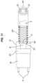
- the leading end side along the longitudinal direction of the elliptic spring SP is locked at the intermediate position between the pin holder H and the standing guide portion 32, the leading end of the elliptic spring SP does not directly come into contact with the rear end corner portion of the boot B. Therefore, the rear end corner portion of the boot B does not interfere with the elliptic spring SP at the assembling time, and it is possible to securely prevent the rear end corner portion from being crushed and damaged (refer to a front state drawing after the assembly in Fig. 11 ).
Landscapes
- Physics & Mathematics (AREA)
- General Physics & Mathematics (AREA)
- Optics & Photonics (AREA)
- Mechanical Coupling Of Light Guides (AREA)
Description
- The present invention relates to a boot used in an optical connector ferrule for forming a muticore collective connector, for example, Mechanically-Transferable-splicing-Connector (hereinafter, refer to as MT connector), Multifiber-Push-on-Connector (hereinafter, refer to as MT connector), and Multifiber-Push-on-Connector (hereinafter, refer to as MPO connector), which is used for connecting optical fiber core wires and optical fiber tape (ribbon fiber) core wires.
- As a connector for collectively connecting, with low loss, SM type optical fiber single core wires and tape core wires, there has been conventionally used a multicore collective connector which can connect the optical fibers efficiently with a high density, with development of a high density multicore cable which has single mode type optical fiber tapes (ribbon fibers), for example, having four cores, eight cores and twelve cores. The connecting method is a method of positioning and fitting ferrules in which the multicore optical fibers are positioned and fixed with two guide pins, and the connector is called as an MT connector since the connector can be applied to a mechanical high-speed switching in addition to the collective connection of the optical fiber tapes, and has been in recent years put to practical use as a connector for connecting the optical fiber tapes having four cores, eight cores and twelve cores of an access series multicore cable.
- Further, in recent years, an MPO connector has been put to practical used, the MPO connector being structured such as to be easily detachable according to a push-pull operation as a multicore collective connector having twenty four cores and seventy two cores further provided for connecting super multicore cables.
- Specifically, as disclosed in patent document 1, there has been known a connector having a ferrule of an optical connector of a system which is provided with a fiber hole in a front end portion and is positioned with the other end ferrule by a fitting pin inserted to a guide pin hole, the ferrule being constructed by a connection end portion which is a part including the fiber hole and the guide pin hole, and a main body rear portion which is the other part than the connection end portion, and the main body rear portion being the portion except the connection end portion, and including an internal space in an inner portion, and the internal space being constructed by a coating insertion portion and a boot insertion portion.
- More specifically, the optical connector in the patent document 1 mentioned above is provided with a pair of right and left positioning guide
pin insertion holes 102 which pass through from a front end surface to a rear end surface of a ferrulemain body 100 as well as being provided with awindow portion 101 for filling an adhesive agent on an upper surface of the ferrulemain body 100, and is structured such that a plurality of optical fiber corewire insertion holes 103 are provided side by side between both guidepin insertion holes 102 in the front end surface, as shown inFigs. 13A and 13B . Further, the connector is structured such that a rear end surface of the ferrulemain body 100 is provided with a rectangular opening shapedinsertion opening portion 104 which inserts a rectangular tubular boot 106 (refer toFigs. 12A and 12B ) thereto and supports it, and a rear end side of the ferrulemain body 100 is provided with acollar portion 105 which protrudes outward from an outer peripheral surface of the ferrulemain body 100. - Accordingly, the rectangular
tubular boot 106 is formed into a flat surface in its upper and lower, and right and left outer wall surfaces, as shown inFigs. 12A and 12B . Further, a pair of widefront opening portions 107a are formed in the front end portion of theboot 106, and a vertical width and a lateral width of thefront opening 107a are set to magnitudes which correspond to a thickness and a lateral width of a single mode type ribbon fiber (optical fiber tape) T. A pair of upper and lower wide ribbonfiber insertion portions 107b are formed in the rear end portion of theboot 106, and a vertical width of the ribbon fiber insertion portions 197b is set to be somewhat smaller than a vertical width of thefront opening portion 107a in the front end portion at such a degree that only a 12-core optical fiber core wire F protruding out of the front end portion of the single mode type ribbon fiber (optical fiber tape) T can protrude outwards. - Further, in the case of connecting two multicore optical cables each having a plurality of optical fibers, the optical cables are connected by inserting connector plugs installed in the respective multicore optical cables into a relay adapter. For example, in the optical fiber multicore connector, the MPO connectors having the MT ferrules built-in are inserted into the relay adapter and are fixed so that ground surfaces of the MT ferrules come into contact in parallel in the same manner as the case of the MT connector, so that the multicore connectors are connected via the relay adapter.
- Conventionally, the MT type optical connector is structured, as shown in
Fig. 14 , such that a pin holder H is arranged so as to hold a rectangulartubular boot 106 protruding to a rear end surface of acollar portion 105 protruding outward from an outer peripheral surface of a ferrulemain body 100, the pin holder H being provided for retaining a positioning pin P and formed into a C-shaped frame, and always applies a forward pressing force to the ferrulemain body 100 by an elliptic spring SP which is installed astride theboot 106 and the pin holder H from a rear side in a pressure contact manner. - Patent Document 1:
Japanese Unexamined Patent Publication No. 2001-83367 -
JP 2004 061883 A -
JP 2002 182067 A -
JP S63 296008 A -
JP 2001 074973 A -
US 2013/028560 A1 discloses an optical fiber assembly with a ferrule and a ferrule boot connected to the ferrule. - In the meantime, in the case of the patent document 1 mentioned above, since the ribbon
fiber insertion portion 107b is hard to be viewed when the ribbon fiber T is inserted into the ribbonfiber insertion portion 107b, it is necessary to insert the ribbon fiber T while viewing from a rear side surface of theboot 106. Therefore, in the presence of two or more ribbonfiber insertion portions 107b, there is a problem that an inserting operability of the ribbon fiber T is inferior. - Further, as shown in
Fig. 14 , the elliptic spring SP is installed astride theboot 106 and the pin holder H from a rear side at the assembling time, and applies the forward pressing force to the ferrulemain body 10. As a result, there is a problem that a rearend corner portion 106A of theboot 106 interferes with the elliptic spring SP and a position of the elliptic spring SP itself is displaced. - Consequently, the present invention is provided while taking the conventionally existing various circumstances mentioned above into consideration, and an object of the present invention is to provide a boot for an optical connector ferrule which can improve an inserting property of a ribbon fiber by applying a guide function of the ribbon fiber to a ribbon fiber insertion portion, and further is structured such that a rear end corner portion of the boot for the optical connector ferrule does not interfere with an elliptic spring at the assembling time.
- To solve the above mentioned problems, there is provided a boot for an optical connector ferrule according to independent claim 1. A further embodiment is provided by the dependent claim.
- According to the present invention, it is possible to improve the inserting property of the ribbon fiber by applying the guide function of the ribbon fiber to the ribbon fiber insertion portion, and it is further possible to prevent the rear end corner portion of the boot for the optical connector ferrule from interfering with the elliptic spring at the assembling time.
- More specifically, according to the present invention, the boot for the optical connector ferrule includes the ribbon fiber insertion portion which is internally provided with the single vertical partition portion or a plurality of vertical partition portions so as to section plural groups of ribbon fibers having a plurality of optical fiber core wires in their leading ends into a plurality of stages and enable to insert the ribbon fibers, and the front opening portion which exposes the optical fiber core wires in the respective leading ends of the inserted ribbon fiber groups to the forward outer side. The boot is insertable to the boot insertion opening portion which is formed in the rear end side of the optical connector ferrule, the fiber guide of each of the ribbon fibers is provided so as to make the rear end portion side of the single vertical partition portion or the plurality of vertical partition portions internally provided in the ribbon fiber insertion portion protrude outward from the ribbon fiber insertion portion. As a result, it is not necessary to insert the ribbon fiber while viewing from the rearward side surface of the boot for the optical connector ferrule when the ribbon fiber is inserted into the ribbon fiber insertion portion, and it is possible to easily insert the ribbon fiber by the fiber guide.
- The fiber guide is formed by provision of an exposure notch portion which is notched at a predetermined length toward an inner side of the ribbon fiber insertion portion while leaving the vertical partition portion, in a side of rear end portion of both upper and lower wall surfaces of the ribbon fiber insertion portion. As a result, it is possible to easily form the fiber guide only by the simple notch formation without taking a lot of trouble and cost for manufacturing.
- The fiber guide is provided with standing guide portions at vertically symmetrical positions in both right and left ends of the fiber guide by being formed into an approximately H-shaped cross section in a rear view while leaving both right and left wall surfaces where the vertical partition portions of the ribbon fiber insertion portion are positioned at a time of forming the exposure notch portion. As a result, it is possible to easily form the standing guide portion only by the simple notch formation. Further, on the basis of the existence of the standing guide portion, both side end portions in a lateral width direction of the ribbon fiber can be smoothly inserted into the ribbon fiber insertion portion while being guided and retained by the standing guide portion when the ribbon fiber is inserted into the ribbon fiber insertion portion.
- The boot includes the elliptic spring which is attached to the boot for the optical connector ferrule for pressing the optical connector ferrule at the fitting time and maintaining the fitting, and the standing guide portion is formed so as to bridge over a part in the longitudinal direction of the elliptic spring. As a result, the rear end corner portion of the boot for the optical connector ferrule does not interfere with the elliptic spring at the assembling time, and it is possible to securely prevent the rear end corner portion from being crushed and damaged.
- The vertical partition portion has the concave portion which is notched into the approximately U-shaped form in the plane view from the rear end portion toward the forward side. As a result, it is easy to carry out an inserting operation of the ribbon fiber into the ribbon fiber insertion portion in the lower side through the concave portion of the vertical partition portion.
-
-
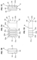
Figs. 1A, 1B and 1C show a boot for an optical connector ferrule according to an embodiment of the claimed invention, in whichFig. 1A is a perspective view as seen from a diagonally forward side,Fig. 1B is a perspective view as seen from a diagonally rearward side, andFig. 1C is a perspective view as seen from the diagonally rearward side in a half notched state; -
Figs. 2A, 2B, 2C, 2D and 2E show the boot for the optical connector ferrule, in whichFig. 2A is a plane view,Fig. 2B is a front elevational view,Fig. 2C is a rear elevational view,Fig. 2D is a side elevational view andFig. 2E is a bottom elevational view; -
Figs. 3A, 3B and 3C show the boot for the optical connector ferrule, in whichFig. 3A is a cross sectional view along a line A-A inFig. 2A ,Fig. 3B is a cross sectional view along a line B-B inFig. 2D andFig. 3C is a cross sectional view along a line C-C inFig. 2C ; -
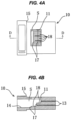
Figs. 4A and 4B show the optical connector ferrule, which does not form part of the claimed invention, in whichFig. 4A is a plane view andFig. 4B is a cross sectional view along a line D-D inFig. 4A ; -
Figs. 5A, 5B, 5C and 5D show a state in which the boot is assembled and used in the optical connector ferrule, in whichFig. 5A is a perspective view of a state as seen from a diagonally rearward side,Fig. 5B is a perspective view of a state as seen from a diagonally forward side,Fig. 5C is a side cross sectional view andFig. 5D is a plan cross sectional view; -
Figs. 6A, 6B, 6C, 6D and 6E show a boot for an optical connector ferrule according to another embodiment, not forming part of the claimed invention, in whichFig. 6A is a plane view,Fig. 6B is a front elevational view,Fig. 6C is a rear elevational view,Fig. 6D is a side elevational view andFig. 6E is a bottom elevational view; -
Figs. 7A, 7B, 7C and 7D show a boot for an optical connector ferrule according to the embodiment not forming part of the claimed invention, in whichFig. 7A is a plane view,Fig. 7B is a front elevational view,Fig. 7C is a rear elevational view andFig. 7D is a side elevational view; -
Fig. 8 is a perspective view showing an example of an overall structure of an MPO connector; -
Figs. 9A, 9B and 9C show an example of the overall structure of the MPO connector, in whichFig. 9A is a side elevational view,Fig. 9B is a front elevational view andFig. 9C is a rear elevational view; -
Fig. 10 is a side elevational view according to a half cross section and shows an internal structure of the MPO connector; -
Fig. 11 is a plane view of a state after an elliptic spring is assembled in the optical connector ferrule that can be used with the boot of the claimed invention; -
Figs. 12A and 12B show a boot for an MT ferrule according to the prior art, in whichFig. 12A is a perspective view as seen from a diagonally forward side andFig. 12B is a perspective view as seen from a diagonally rearward side; -
Figs. 13A and 13B show a state in which a boot is assembled and used in an optical connector ferrule according to the prior art, in whichFig. 13A is a perspective view of a state as seen from a diagonally rearward side andFig. 13B is a side cross sectional view; and -
Figs. 14A and 14B show an example in which an elliptic spring is assembled in the optical connector ferrule according to the prior art, in whichFig. 14A is a plane view of a state before the assembly andFig. 14B is a plane view of a state after the assembly. - A description will be in detail given below of an embodiment according to the present invention with reference to the accompanying drawings.
- In the present embodiment, an optical connector ferrule for forming a multicore collective connector according to the present invention is constructed by a ferrule
main body 10 which is used as a multicore collective MT connector and is molded by resin into an approximately rectangular casing shape, the multicore collective MT connector to which a high-density multicore cable can be connected, the high-density multicore cable in which ribbon fibers T such as twelve-core single mode type optical fiber tapes are accommodated at plural stages, for example, vertically two stages, as shown inFigs. 4 and5 . The connecting method is set to a method of positioning and fitting the ferrulemain bodies 10 each other with two guide pins, the ferrulemain bodies 10 to which multicore optical fibers are positioned and fixed. - Therefore, the following description relates to the MT connector according to the above structure, however, the present invention can be applied to an MT connector for a connecting high-density multicore cable which accommodates plural groups of ribbon fibers T corresponding to single mode type optical fiber tapes, for example, having four cores and eight cores, and further applied to a multicore collective connector, for example, an MPO connector mentioned later, which can be easily attached and detached according to a push-pull operation as a multicore collective connector having sixteen cores or eighty cores for connecting super multicore cables, without being limited to the MT connector. In the following description, the single mode type optical fiber tape is called as a ribbon fiber T, and the boot for the optical connector ferrule is abbreviated simply to a boot B.
- The boot B is insertable to an
insertion opening portion 14 which is formed in a rear end surface side of the ferrulemain body 10, is mentioned later and is formed into a rectangular opening shape, the boot B to which ribbon fibers T obtained, for example, by bundling optical fiber core wires F of twelve cores into a tape are inserted and fixed at vertically two stages. - Here, a description will be given of a specific structure of the boot B. As shown in
Figs. 1A, 1B, 1C ,2A, 2B, 2C, 2D, 2E ,3A, 3B and 3C , a horizontal and vertical width of a sidefront opening portion 21a in a front end portion of the boot B is a magnitude which corresponds to a horizontal and vertical length of the ribbon fiber T, and a vertical width of a wide opening shaped ribbonfiber insertion portion 21b in a rear end portion of the boot B is somewhat greater than a vertical width of thefront opening portion 21a in the front end portion in such a degree that only upper and lower optical fiber core wires F, for example, having twelve cores, which protrude out of a front end portion of the ribbon fibers T in vertically two stages can protrude outward. - More specifically, a
vertical partition portion 31 is horizontally provided in an inner portion of the ribbonfiber insertion portion 21b so as to section two groups of ribbon fibers T having a plurality of optical fiber core wires in their leading ends into vertically two stages and enable the insertion of the groups of ribbon fibers T. - A leading end edge of the
vertical partition portion 31 is arranged in somewhat inward back side in comparison with a position of thefront opening portion 21a. A rear end of the ribbonfiber insertion portion 21b is formed into vertically two stages of insertion ports, and vertically two stages of inside openingportions 34 are formed in an inward back side of thefront opening portion 21a, in a leading end edge side of thevertical partition portion 31 so as to be communicated with the insertion ports. - Further, each of rear end portion sides of both upper and lower wall surfaces of the
ribbon insertion portion 21b forms anexposure notch portion 30 by being notched at a predetermined length toward an inner side of the ribbonfiber insertion portion 21b while leaving thevertical partition portion 31 which is provided at the center in a vertical direction of the boot B. As a result, the rear end portion side of thevertical partition portion 31 comes to a state of being protruded outward from the ribbonfiber insertion portion 21b, and a fiber guide G of each of the ribbon fibers T is formed. - At this time, since the fiber guide G is formed into an approximately H-shaped cross section in a rear view (a transversely T-shaped form in each of right and left sides, refer to
Figs. 1B, 1C and2C ) while leaving both right and left wall surfaces where thevertical partition portions 31 of the ribbonfiber insertion portion 21b are positioned, standingguide portions 32 are formed at vertically symmetrical positions in both the right and left ends of the fiber guide G. - Further, a
concave portion 33 notched into an approximately U-shaped form in a plane view from a rear end portion toward a forward side is formed in thevertical partition portion 31, thereby facilitating an inserting operation of the ribbon fiber T into the ribbonfiber insertion portion 21b in a lower side through theconcave portion 33 of thevertical partition portion 31. - In the present embodiment, the fiber guide G is formed by the
vertical partition portion 31 which is formed by notching theexposure notch portion 31, however, the forming method is not limited to this, and the fiber guide G may be formed by integrally injection molding only thevertical partition portion 31 from the ribbonfiber insertion portion 21b extensionally at a time of manufacturing the boot B without necessity of a processing operation according to a notching formation after the manufacturing. Further, in the present embodiment, the ribbonfiber insertion portion 21b can insert two groups of ribbon fibers T while sectioning the ribbon fibers T into vertical two stages by the singlevertical partition portion 31, however, is not limited to this and may be structured such that the ribbonfiber insertion portion 21b can insert plural groups of ribbon fibers T while sectioning the ribbon fibers T into vertically plural stages by two or morevertical partition portions 31. - The boot B is provided with two
protrusions insertion opening portion 14 formed in a rear end side of the ferrulemain body 10, on a whole surface of a surface along a perpendicular direction to an inserting direction of the boot B. The number of theseprotrusions protrusions - Further, as shown in
Figs. 1A, 1B, 1C ,2A and 2E , four adhesiveagent reservoir portions protrusions Figs. 4 and5 ) of the ferrulemain body 10 and leaks out of a gap between the boot B and theinsertion opening portion 14 of the ferrulemain body 10. Specifically, thefirst protrusion 22a is formed in such a manner as to be adjacent to a rear edge side of the adhesiveagent reservoir portion 23a which is positioned in the forefront end side, thesecond protrusion 22b is formed in such a manner as to be adjacent to a rear edge side of the adhesiveagent reservoir portion 23b which is positioned at the second rearward, and thethird protrusion 22c is formed in such a manner as to be adjacent to a rear edge side of the adhesiveagent reservoir portion 23c which is positioned at the third rearward. - The
protrusions agent reservoir portions main body 10. As mentioned above, the horizontal and vertical width of theinsertion opening portion 14 of the ferrulemain body 10 is set to be approximately the same or somewhat greater than the horizontal and vertical width of the boot B, and a height from the surface of the boot B is set, for example, to about 0.1 to 0.5 mm in correspondence to the horizontal and vertical width of the boot B in order to make theprotrusions insertion opening portion 14 of the ferrulemain body 10. it goes without saying that the height does not restrict the technical scope of the present invention. - Further, as shown in
Figs. 1A, 1B and 1C , an adhesiveagent induction groove 24 for inducing the adhesive agent V into the adhesiveagent reservoir portion 23a is provided at the center of a forward edge side (a portion forming a forward downward inclined surface in the drawing) of the adhesiveagent reservoir portion 23a which is positioned in the forefront end side of each of both upper and lower surfaces of the boot B, and the adhesive agent V is induced to the adhesiveagent reservoir portion 23a through the adhesiveagent induction groove 24, so that the adhesive agent V is filled like an approximately T-shaped form in a plane view. - Describing a specific structure of the ferrule
main body 10, as shown inFigs. 4A and 4B , in the rear end surface side of the ferrulemain body 10, there is formed the rectangular opening shapedinsertion opening portion 14 for installing the approximately rectangular tubular boot B to which the ribbon fiber T obtained by bundling twelve cores of optical fiber core wires F like the tape, as mentioned above. An internal portion of the ferrulemain body 10 forms an accommodating space portion S of the boot B in such a manner that a part (about half) of the front end side of the boot B is accommodated through theinsertion opening portion 14. - Further, as shown in
Figs. 4B ,5B, 5C and 5D , optical fiber core wire insertion holes 13 forming twelve small holes are pierced in the front end surface side of the ferrulemain body 10 up to a position which is inward back portion of theinsertion opening portion 14 of the ferrule main body 10 (a forward end inner wall of the accommodating space portion S of the boot B), whereby each of the optical fiber core wire insertion holes 13 comes to a state of being communicated with the accommodating space portion S of the boot B. - in the illustrated example (refer to
Figs. 4B and5C ), twostep portions 17 are formed at positions short of the inward back portion of the accommodating space portion S so as to face to rear side edge portion positions of the adhesive agent fillingwindow portion 11, and a lower portion side of a leading end surface of the inserted boot B is locked at the position short of the adhesive agent fillingwindow portion 11 by thelower step portion 17 among twostep portions 17. At this time, the respective leading end portions of twelve cores of optical fiber core wires F protruding out of the leading end side of the ribbon fiber T in the upper stage are inserted to twelve optical fiber core wire insertion holes 13 in the upper stage from the inner side of the accommodating space portion S of the boot B, and the respective leading end portions of twelve cores of optical fiber core wires F protruding out of the leading end side of the ribbon fiber T in the lower stage are inserted to twelve optical fiber core wire insertion holes 13 in the lower stage from the inner side of the accommodating space portion S of the boot B, thereby exposing the end surfaces of the leading end portions to the front surface side of the ferrulemain body 10 in both the upper and lower stages. - Further, the approximately rectangular opening shaped adhesive agent filling
window portion 11 is pierced approximately at the center of the upper surface of the ferrulemain body 10 as mentioned above, an upper half of the ferrulemain body 10 is under a bored state from the inward back portion side of theinsertion opening portion 14 of the ferrule main body 10 (the forward end inner wall of the accommodating space portion S of the boot B) to the rear end opening portions of respective upper and lower twelve optical fiber core wire insertion holes 13, and twelveU-shaped guide grooves 18 are totally formed from the rear end opening portions of the optical fiber core wire insertion holes 13 to positions approximately facing to the center of the adhesive agent filling window portion 11 (the upper surfaces of two step portions 17) (refer toFigs. 4B and5 ). - Therefore, in
Fig. 4A , theU-shaped guide grooves 18 can be viewed through the adhesive agent fillingwindow portion 11 over the rear end opening portions of the optical fiber corewire insertion hole 13 and the upper surfaces of twostep portions 17. Further, in a state in which the boot B is installed to theinsertion opening portion 14 of the ferrulemain body 10 and the respective leading end portions of the optical fiber core wires F are inserted to the respective optical fiber core wire insertion holes 13 in the upper and lower stages, respective twelve cores of optical fiber core wires F in the upper and lower stages protruding out of the leading end side of the ribbon fiber T, for example, the single mode type optical fiber tape are firmly fixed to the ferrulemain body 10 by injecting the adhesive agent V, for example, of an epoxy resin from the adhesive agent fillingwindow portion 13. - Further, as shown in
Figs. 5A, 5B and 5D , a pair of right and left positioning guide pin insertion holes 12 are provided in a penetrating manner from the front end surface to the rear end surface of the ferrulemain body 10, and the optical fiber core wire insertion holes 13 in upper and lower two stages are under a state of being arranged side by side horizontally in a line between both the guide pin insertion holes 12 in the front end surface of the ferrulemain body 10. - As shown in
Figs. 4 to 5 , the rear end side of the ferrulemain body 10 is provided with acollar portion 15 which protrudes outward from an outer peripheral surface of the ferrulemain body 10. - Next, a description will be given in detail of an example of an assembly use of the embodiment which is constructed as mentioned above.
- Two ribbon fibers T are sectioned into upper and lower two stages and inserted into an inner portion of the ribbon
fiber insertion portion 21b of the boot B shown inFigs. 1 to 3 . First of all, the ribbon fiber T in the lower side is first inserted. More specifically, the ribbon fiber T is inserted along the fiber guide G formed by thevertical partition portion 31 protruding rearward of the ribbonfiber insertion portion 21b and while making both right and left side downward standingguide portions 32 guide both end sides of the lateral width of the ribbon fiber T. At this time, it is possible to discriminate whether or not the ribbon fiber T is securely inserted into the inner portion of the ribbonfiber insertion portion 21b through theconcave portion 33 of the fiber guide G (the protruding vertical partition portion 31). - After the insertion, the optical fiber core wire F protrudes out of the
inner opening portion 34 in the lower stage of the ribbonfiber insertion portion 21b (the lower side of the vertical partition portion 31), and the end surface of the optical fiber core wire F is under a state of being pulled forward out of thefront opening portion 21a. - Next, the ribbon fiber T in the upper side is inserted. More specifically, the ribbon fiber T is inserted along the fiber guide G and while making both right and left upward standing
guide portions 32 guide both end sides of the lateral width of the ribbon fiber T. After the insertion, the optical fiber core wire F protrudes out of theinner opening portion 34 in the upper stage of the ribbonfiber insertion portion 21b (the upper side of the vertical partition portion 31), and the end surface of the optical fiber core wire F is under a state of being pulled forward out of thefront opening portion 21a. - Next, as shown in
Fig. 5 , the boot B is inserted to theinsertion opening portion 14 of the ferrulemain body 10, the boot B to which the ribbon fibers T obtained by bundling twelve cores of optical fiber core wires F like the tape are installed in upper and lower two stages. At this time, each of threeprotrusions main body 10. - Further, at the same time as the leading end surface of the boot B inserted as mentioned above is locked in its lower portion side at the position short of the adhesive agent filling
window portion 11 by therear step portion 17 among two front and rear step portions within the accommodating space portion S of the ferrulemain body 10, the leading end portion of each of twelve cores of optical fiber core wires F in the leading end side of the ribbon fibers T in upper and lower two stages is inserted to each of twelve optical fiber core wire insertion holes 13 in the upper and lower stages along theU-shaped guide groove 18, and the end surface of the leading end portion is exposed to the front surface side of the ferrulemain body 10. - Finally, a root portion of each of the optical fiber core wires F is adhesion integrated with the ferrule
main body 10 by filling the adhesive agent V from the adhesive agent fillingwindow portion 11 of the ferrulemain body 10, the optical fiber core wires F being constructed by respective upper and lower twelve cores (totally twenty four cores) protruding out of the leading end side of the ribbon fiber T, and both of the leading end portion of the ribbon fiber T and the root portion of the optical fiber core wire F protruding out of the leading end portion are firmly fixed by the adhesive agent V. At this time, the adhesive agent V is induced to the adhesiveagent reservoir portion 23a which is positioned in the forefront end side of each of the upper and lower surfaces of the boot B through the adhesiveagent induction groove 24 which is provided at the center of the boot B, and the adhesive agent V is filled like an approximately T-shaped form in a plane view. - In this connection, the description is all given above of the MT connector, however, the present invention can be applied to the other types of multicore optical connectors.
- In the present example, not forming part of the claimed invention, the standing
guide portion 32 is formed into an approximately circular arc shape in a side view from each of the upper side wall surface and the lower side wall surface of the ribbonfiber insertion portion 21b up to thevertical partition portion 31. In the present example, the same reference numerals are attached to the same constituting portions as those of the previous embodiment and a detailed description thereof will be omitted. It goes without saying that the same operations and effects as those of the previous embodiment can be achieved in the present example. - In the present example, not forming part of the claimed invention, as shown in
Fig. 7 , anexposure notch portion 40 is provided by notching a rear end portion of the ribbonfiber insertion portion 21b toward a diagonally rear side from an upper wall surface side to a lower wall surface side, in the ribbonfiber insertion portion 21b which can insert one ribbon fiber T having a lot of optical fiber core wires in its leading end and is provided with a single insertion hole having novertical partition portion 31. Therefore, alower wall surface 41 in a leading end portion exposed by theexposure notch portion 40 and both right and left wall surfaces 42 approximately having a triangular shape form the fiber guide G of the ribbon fiber T. In the present example, the same reference numerals are attached to the same constituting portions as those of the previous embodiment, and a detailed description thereof will be omitted (in this case, theprotrusion 22a is additionally formed in the vicinity of the adhesiveagent reservoir portion 23a inFig. 7 ). It goes without saying that the same operations and effects as those of the previous embodiment can be achieved in the present example. - A description will be given below of a case that the boot B according to the structure of the present embodiment is applied to a multicore collective connector such as an
MPO connector 50 which can be easily attached and detached according to a push-pull operation. In this case, theMPO connector 50 is a multicore optical connector which employs an MT type optical connector, for example, an F12 type multicore optical fiber connector (JIS.C5981) as the optical connector ferrule. - As shown in
Figs. 8 ,9A, 9B, 9C and 10 , theMPO connector 50 is constructed by anMPO boot 51, acoupling 52, aspring push 56 which is inward fitted to theMPO boot 51 and ahousing 53, a coil spring SP1 which is interposed between a lockingprojection 52a provided in front of an inner side of thecoupling 52 and anaccommodating recess portion 53a provided at the rear of thehousing 53, and energizes thecoupling 52 forward, a ferrulemain body 10 which is inward wrapped in thehousing 53, is protruded and energized its leading end to thespring push 56 via an elliptic spring SP from a leading end of thehousing 53, and accommodates a lot of optical fiber core wires F in a state in which their end surfaces are exposed, and a positioning pin P which is extended outward from the ferrulemain body 10. - A
key projection 54 is protruded in a longitudinal direction at the center of an upper wall surface of thehousing 53, and akey groove 55 is protruded in a longitudinal direction at the center of an upper wall inner surface of thecoupling 52 in correspondence thereto. On the basis of a loose fitting of thekey projection 54 and thekey groove 55, thecoupling 52 can slide a compression coil spring SP1 rearward in relation to thehousing 53 while compressing. Therefore, it is possible to expose (forward move) thehousing 53 according to a sliding operation of thecoupling 52 when the ferrulemain body 10 is fitted to the other side connector (not shown). - Further, in
Fig. 11 , reference symbol H denotes a pin holder which is provided for retaining a positioning pin P and is formed into a C-shaped frame. The pin holder H is arranged so as to hold the boot B protruding to a rear side of the ferrulemain body 10, and the elliptic spring SP always applies a forward pressing force to the ferrulemain body 10. In other words, the elliptic spring SP is attached so as to wind up the ribbon fiber T in the rear side of the boot B for maintaining the fitting by pressing theoptical connector ferrule 10 when the ferrulemain body 10 is fitted to the other side connector (not shown). In this case, the standingguide portion 32 in the fiber guide G is formed so as to bridge a part (an outer side) in the longitudinal direction of the elliptic spring SP. - Specifically, since the leading end side along the longitudinal direction of the elliptic spring SP is locked at the intermediate position between the pin holder H and the standing
guide portion 32, the leading end of the elliptic spring SP does not directly come into contact with the rear end corner portion of the boot B. Therefore, the rear end corner portion of the boot B does not interfere with the elliptic spring SP at the assembling time, and it is possible to securely prevent the rear end corner portion from being crushed and damaged (refer to a front state drawing after the assembly inFig. 11 ). -
- B
- boot for optical connector ferrule (boot)
- V
- adhesive agent
- T
- optical fiber tape
- F
- optical fiber corner wire
- S
- accommodating space portion
- G
- fiber guide
- H
- pin holder
- SP
- elliptic spring
- SP1
- compression coil spring
- P
- positioning pin
- 10
- ferrule main body
- 11
- adhesive agent filling window portion
- 12
- guide pin insertion hole
- 13
- optical fiber core wire insertion hole
- 14
- boot insertion opening portion
- 15
- collar portion
- 17
- step portion
- 18
- guide groove
- 21a
- front opening portion
- 21b
- ribbon fiber insertion portion
- 22a, 22b, 22c
- protrusion
- 23a, 23b, 23c, 23d
- adhesive agent reservoir portion
- 24
- adhesive agent induction groove
- 30, 40
- exposure notch portion
- 31
- vertical partition portion
- 32
- standing guide portion
- 33
- concave portion
- 34
- inner opening portion
- 41
- lower wall surface
- 42
- both right and left wall surfaces
- 50
- MPO connector
- 51
- MPO boot
- 52
- coupling
- 52a
- locking projection
- 53
- housing
- 53a
- accommodating recess portion
- 54
- key projection
- 55
- key groove
- 56
- spring push
- 100
- ferrule main body
- 101
- window portion
- 102
- guide pin insertion hole
- 103
- optical fiber core wire insertion hole
- 104
- insertion opening portion
- 105
- collar portion
- 106
- boot
- 107a
- front opening portion
- 107b
- ribbon fiber insertion portion
Claims (2)
- A boot for an optical connector ferrule, the boot comprising:a ribbon fiber insertion portion (21b) which is internally provided with a single vertical partition portion (31) or a plurality of vertical partition portions configured to section plural groups of ribbon fibers (F) having a lot of optical fiber core wires in their leading ends into a plurality of upper and lower stages and enable the insertion of said plural groups of ribbon fibers;a front opening portion (21a) which exposes the optical fiber core wires in the respective leading ends of said inserted ribbon fiber plural groups to a forward outer side; wherein the boot is insertable to a boot insertion opening portion (14) which is formed in a rear end side of the optical connector ferrule (10),wherein each of rear end portion sides of both upper and lower wall surfaces of the ribbon insertion portion (21b) forms an exposure notch portion (30) by being notched at a predetermined length toward an innerside of the ribbon fiber insertion portion (21b) while leaving said single vertical partition portion (31) or said plurality of vertical partition portions,a fiber guide (G) of each of said plural groups of ribbon fibers is provided by the rear end portion side of said single vertical partition portion (31) or said plurality of vertical partition portions internally provided in said ribbon fiber insertion portion (21b), the end portion side of said single vertical partition portion (31) or said plurality of vertical partition portions protruding outward from said exposure notch portion (30) of said ribbon fiber insertion portion (21b), whereinsaid fiber guide (G) is provided with standing guide portions (32) at vertically symmetrical positions in both right and left ends of the fiber guide by being formed into an approximately H-shaped cross section in a rear view while leaving both right and left wall surfaces where said vertical partition portions of said ribbon fiber insertion portion are positioned at a time of forming said exposure notch portion (30),wherein said boot further comprises an elliptical spring (SP) which is attached to the boot for said optical connector ferrule (10) and configured to press said optical connector ferrule at the fitting time and maintaining the fitting, andwherein said standing guide portions (32) are formed so as to bridge over a part in a longitudinal direction of said elliptic spring (SP).
- The boot for the optical connector ferrule according to claim 1, wherein said single vertical partition portion (31) or said plurality of vertical partition portions have a concave portion (33) which is notched into an approximately U-shaped form in a plane view from a rear end portion toward a forward side.
Applications Claiming Priority (1)
| Application Number | Priority Date | Filing Date | Title |
|---|---|---|---|
| JP2015237590A JP6649065B2 (en) | 2015-12-04 | 2015-12-04 | Boots for optical connector ferrule |
Publications (2)
| Publication Number | Publication Date |
|---|---|
| EP3176617A1 EP3176617A1 (en) | 2017-06-07 |
| EP3176617B1 true EP3176617B1 (en) | 2024-05-01 |
Family
ID=57442571
Family Applications (1)
| Application Number | Title | Priority Date | Filing Date |
|---|---|---|---|
| EP16201453.4A Active EP3176617B1 (en) | 2015-12-04 | 2016-11-30 | Boot for optical connector ferrule |
Country Status (4)
| Country | Link |
|---|---|
| US (1) | US9891391B2 (en) |
| EP (1) | EP3176617B1 (en) |
| JP (1) | JP6649065B2 (en) |
| CN (1) | CN106873084B (en) |
Families Citing this family (36)
| Publication number | Priority date | Publication date | Assignee | Title |
|---|---|---|---|---|
| CN108139547B (en) * | 2015-10-12 | 2020-09-08 | 3M创新有限公司 | Optical waveguide positioning features in a multi-waveguide connector |
| US12271040B2 (en) | 2017-06-28 | 2025-04-08 | Corning Research & Development Corporation | Fiber optic extender ports, assemblies and methods of making the same |
| HRP20220022T1 (en) | 2017-06-28 | 2022-04-01 | Corning Research & Development Corporation | Compact fiber optic connectors |
| US11300746B2 (en) | 2017-06-28 | 2022-04-12 | Corning Research & Development Corporation | Fiber optic port module inserts, assemblies and methods of making the same |
| US12571977B2 (en) | 2017-06-28 | 2026-03-10 | Corning Research & Development Corporation | Multiports and other devices having optical connection ports with securing features and methods of making the same |
| US11187859B2 (en) | 2017-06-28 | 2021-11-30 | Corning Research & Development Corporation | Fiber optic connectors and methods of making the same |
| US11668890B2 (en) | 2017-06-28 | 2023-06-06 | Corning Research & Development Corporation | Multiports and other devices having optical connection ports with securing features and methods of making the same |
| JP6898051B2 (en) * | 2017-07-12 | 2021-07-07 | 三和電気工業株式会社 | Optical connector plug accident prevention device |
| US10746938B2 (en) | 2017-11-17 | 2020-08-18 | Commscope Technologies Llc | Fiber optic connectors |
| US11215763B2 (en) | 2018-05-28 | 2022-01-04 | Japan Communication Accessories Manufacturing Co., Ltd. | Elastic member and optical connector |
| WO2020046711A1 (en) * | 2018-08-31 | 2020-03-05 | Commscope Technologies Llc | Ferrule boot for optical connectors |
| PL3887883T3 (en) | 2018-11-29 | 2024-04-22 | Corning Research & Development Corporation | Multiport having connection ports with rotating actuators |
| WO2020242847A1 (en) | 2019-05-31 | 2020-12-03 | Corning Research & Development Corporation | Multiports and other devices having optical connection ports with sliding actuators and methods of making the same |
| US11294133B2 (en) | 2019-07-31 | 2022-04-05 | Corning Research & Development Corporation | Fiber optic networks using multiports and cable assemblies with cable-to-connector orientation |
| JP2021043422A (en) * | 2019-09-13 | 2021-03-18 | 小池 康博 | Bulk molding multi-optical transmission sheet assembly, connection structure, optical module, active optical cable and its manufacturing method |
| US11487073B2 (en) | 2019-09-30 | 2022-11-01 | Corning Research & Development Corporation | Cable input devices having an integrated locking feature and assemblies using the cable input devices |
| EP3805827B1 (en) | 2019-10-07 | 2025-07-30 | Corning Research & Development Corporation | Fiber optic terminals and fiber optic networks having variable ratio couplers |
| PL4045957T3 (en) | 2019-10-18 | 2024-04-29 | Corning Research & Development Corporation | Terminals having optical connection ports with securing features providing stable retention forces |
| US11650388B2 (en) | 2019-11-14 | 2023-05-16 | Corning Research & Development Corporation | Fiber optic networks having a self-supporting optical terminal and methods of installing the optical terminal |
| US11536921B2 (en) | 2020-02-11 | 2022-12-27 | Corning Research & Development Corporation | Fiber optic terminals having one or more loopback assemblies |
| EP4158401A1 (en) | 2020-05-26 | 2023-04-05 | Corning Research & Development Corporation | Fiber optic connectors having one or more securing buttons |
| EP4172671B1 (en) | 2020-06-29 | 2026-01-21 | Corning Research & Development Corporation | Terminals having a multi-fiber optical connection port that inhibits damage from single-fiber connectors |
| US11604320B2 (en) | 2020-09-30 | 2023-03-14 | Corning Research & Development Corporation | Connector assemblies for telecommunication enclosures |
| PL4237889T3 (en) | 2020-10-30 | 2026-01-26 | Corning Research & Development Corporation | FEMALE FIBER OPTIC CONNECTORS WITH LOCKING ARM WITH ROCKING MECHANISM |
| EP4252055B1 (en) | 2020-11-25 | 2026-06-03 | Corning Research & Development Corporation | Multiports and other devices having optical connection ports with rotating actuators pivotly mounted and methods of making the same |
| US11686913B2 (en) | 2020-11-30 | 2023-06-27 | Corning Research & Development Corporation | Fiber optic cable assemblies and connector assemblies having a crimp ring and crimp body and methods of fabricating the same |
| US11994722B2 (en) | 2020-11-30 | 2024-05-28 | Corning Research & Development Corporation | Fiber optic adapter assemblies including an adapter housing and a locking housing |
| US11880076B2 (en) | 2020-11-30 | 2024-01-23 | Corning Research & Development Corporation | Fiber optic adapter assemblies including a conversion housing and a release housing |
| US11927810B2 (en) | 2020-11-30 | 2024-03-12 | Corning Research & Development Corporation | Fiber optic adapter assemblies including a conversion housing and a release member |
| WO2022232508A1 (en) * | 2021-04-30 | 2022-11-03 | Commscope Technologies Llc | Pitch conversion ferrule boot |
| US11947167B2 (en) | 2021-05-26 | 2024-04-02 | Corning Research & Development Corporation | Fiber optic terminals and tools and methods for adjusting a split ratio of a fiber optic terminal |
| TWI810928B (en) * | 2022-05-09 | 2023-08-01 | 立佳興業股份有限公司 | Optical connector |
| TWI892044B (en) * | 2022-09-26 | 2025-08-01 | 簡志澄 | Multi-core fiber optic headgear |
| EP4609246A1 (en) * | 2022-10-28 | 2025-09-03 | SENKO Advanced Components, Inc. | Mpo connector and push-pull boot therefor |
| JPWO2025115357A1 (en) * | 2023-12-01 | 2025-06-05 | ||
| WO2025174932A1 (en) * | 2024-02-13 | 2025-08-21 | Us Conec Ltd. | Hybrid ferrule boot for standard and small od fibers |
Family Cites Families (20)
| Publication number | Priority date | Publication date | Assignee | Title |
|---|---|---|---|---|
| CA1283569C (en) * | 1986-03-14 | 1991-04-30 | Toshiaki Kakii | Optical connector and splicer |
| JPH0654364B2 (en) * | 1987-05-28 | 1994-07-20 | 株式会社フジクラ | Ferrule for multi-core optical fiber connection |
| US5815621A (en) * | 1996-05-23 | 1998-09-29 | Sumitomo Electric Industries, Ltd. | Optical fiber connector ferrule with die and method of manufacturing same |
| JPH09325238A (en) * | 1996-06-07 | 1997-12-16 | Sumitomo Electric Ind Ltd | Multi-fiber optical connector |
| JPH10246839A (en) | 1997-03-05 | 1998-09-14 | Fujitsu Ltd | Optical semiconductor module |
| KR100713430B1 (en) | 1999-06-01 | 2007-05-04 | 니폰덴신뎅와 가부시키가이샤 | Optical connector plug, manufacturing method and assembly tool |
| JP3543319B2 (en) * | 1999-08-31 | 2004-07-14 | 住友電気工業株式会社 | Ferrule for optical connector |
| JP2001083367A (en) | 1999-09-14 | 2001-03-30 | Fujikura Ltd | Optical connector |
| JP3801464B2 (en) | 2000-07-03 | 2006-07-26 | 矢崎総業株式会社 | Hybrid connector |
| JP2002182067A (en) * | 2000-12-19 | 2002-06-26 | Nippon Telegr & Teleph Corp <Ntt> | Ferrule for optical fiber connector |
| US6676300B2 (en) | 2001-01-25 | 2004-01-13 | Sumitomo Electric Industries, Ltd. | Ferrule for optical connector and making method thereof |
| JP3513114B2 (en) | 2001-03-02 | 2004-03-31 | ヒロセ電機株式会社 | Ferrule holding structure |
| JP3786581B2 (en) | 2001-03-02 | 2006-06-14 | ヒロセ電機株式会社 | Optical connector parts |
| JP4053368B2 (en) * | 2002-07-29 | 2008-02-27 | 株式会社フジクラ | Optical connector boot and optical connector |
| JP4395389B2 (en) | 2004-02-23 | 2010-01-06 | 株式会社フジクラ | Optical fiber tape core protecting member and optical fiber connector ferrule connection method |
| US20060115218A1 (en) | 2004-11-29 | 2006-06-01 | Us Conec, Ltd. | Boot for an optical ferrule |
| US7534050B2 (en) | 2007-04-13 | 2009-05-19 | Adc Telecommunications, Inc. | Field terminatable fiber optic connector assembly |
| US8622634B2 (en) * | 2011-07-29 | 2014-01-07 | Corning Cable Systems Llc | Optical fiber assemblies and methods of fabricating optical fiber assemblies |
| WO2013019189A1 (en) * | 2011-07-29 | 2013-02-07 | Hewlett-Packard Development Company, L.P. | Fiber optic connectors |
| JP6234243B2 (en) | 2014-01-24 | 2017-11-22 | オリンパス株式会社 | Optical fiber connection adapter and endoscope apparatus |
-
2015
- 2015-12-04 JP JP2015237590A patent/JP6649065B2/en active Active
-
2016
- 2016-11-28 US US15/361,689 patent/US9891391B2/en active Active
- 2016-11-30 EP EP16201453.4A patent/EP3176617B1/en active Active
- 2016-12-01 CN CN201611088966.0A patent/CN106873084B/en active Active
Also Published As
| Publication number | Publication date |
|---|---|
| JP6649065B2 (en) | 2020-02-19 |
| CN106873084A (en) | 2017-06-20 |
| US9891391B2 (en) | 2018-02-13 |
| JP2017102390A (en) | 2017-06-08 |
| CN106873084B (en) | 2020-06-26 |
| US20170160494A1 (en) | 2017-06-08 |
| EP3176617A1 (en) | 2017-06-07 |
Similar Documents
| Publication | Publication Date | Title |
|---|---|---|
| US9891391B2 (en) | Boot for optical connector ferrule | |
| JP6557052B2 (en) | Optical connector ferrule | |
| US9383521B2 (en) | Cable fixture assembly for fastening at least one cable at a cable carrier as well as a splitter comprising such cable fixture assembly | |
| US8740479B2 (en) | Optical connector and method for assembling same | |
| US8824850B2 (en) | Insect-infestation prevention device for a telecommunications equipment housing | |
| CN101669054B (en) | Optical fiber connector and optical cable | |
| US8297850B2 (en) | Optical connector, and method of assembling optical connector | |
| US20100092136A1 (en) | Fanout cable assembly and method | |
| EP3101455B1 (en) | Boot and optical connector ferrule | |
| CN108027478B (en) | The optical fiber connector lock pin that access opening is extended | |
| CN111856660B (en) | Optical fiber adapter | |
| JP2003014983A (en) | Optical connector plug | |
| US12353029B2 (en) | Optical fiber connector | |
| US8070366B1 (en) | Optical fiber connector and method | |
| JP2009193030A (en) | Optical ferrule with optical fiber | |
| CN102326111A (en) | Insert for an optical fiber assembly and optical fiber assembly using such an insert | |
| KR100570421B1 (en) | Connector for plastic optical cable | |
| US6840681B2 (en) | Tandem type optical connector | |
| WO2022158018A1 (en) | Ferrule and ferrule structure | |
| KR101349529B1 (en) | Fiber optic connector | |
| CN111061016A (en) | An optical fiber connector with a protective shell | |
| KR101185537B1 (en) | Field installable optical fiber connector | |
| KR20110009064U (en) | Ribbon-shaped multicore fiber branch with protective tube | |
| EP2256529A1 (en) | Optical connector | |
| JP2005345840A (en) | MT connector boots |
Legal Events
| Date | Code | Title | Description |
|---|---|---|---|
| AK | Designated contracting states |
Kind code of ref document: A1 Designated state(s): AL AT BE BG CH CY CZ DE DK EE ES FI FR GB GR HR HU IE IS IT LI LT LU LV MC MK MT NL NO PL PT RO RS SE SI SK SM TR |
|
| AX | Request for extension of the european patent |
Extension state: BA ME |
|
| PUAI | Public reference made under article 153(3) epc to a published international application that has entered the european phase |
Free format text: ORIGINAL CODE: 0009012 |
|
| STAA | Information on the status of an ep patent application or granted ep patent |
Free format text: STATUS: THE APPLICATION HAS BEEN PUBLISHED |
|
| STAA | Information on the status of an ep patent application or granted ep patent |
Free format text: STATUS: REQUEST FOR EXAMINATION WAS MADE |
|
| 17P | Request for examination filed |
Effective date: 20171127 |
|
| RBV | Designated contracting states (corrected) |
Designated state(s): AL AT BE BG CH CY CZ DE DK EE ES FI FR GB GR HR HU IE IS IT LI LT LU LV MC MK MT NL NO PL PT RO RS SE SI SK SM TR |
|
| STAA | Information on the status of an ep patent application or granted ep patent |
Free format text: STATUS: EXAMINATION IS IN PROGRESS |
|
| 17Q | First examination report despatched |
Effective date: 20210330 |
|
| GRAP | Despatch of communication of intention to grant a patent |
Free format text: ORIGINAL CODE: EPIDOSNIGR1 |
|
| STAA | Information on the status of an ep patent application or granted ep patent |
Free format text: STATUS: GRANT OF PATENT IS INTENDED |
|
| INTG | Intention to grant announced |
Effective date: 20231218 |
|
| GRAS | Grant fee paid |
Free format text: ORIGINAL CODE: EPIDOSNIGR3 |
|
| GRAA | (expected) grant |
Free format text: ORIGINAL CODE: 0009210 |
|
| STAA | Information on the status of an ep patent application or granted ep patent |
Free format text: STATUS: THE PATENT HAS BEEN GRANTED |
|
| AK | Designated contracting states |
Kind code of ref document: B1 Designated state(s): AL AT BE BG CH CY CZ DE DK EE ES FI FR GB GR HR HU IE IS IT LI LT LU LV MC MK MT NL NO PL PT RO RS SE SI SK SM TR |
|
| REG | Reference to a national code |
Ref country code: GB Ref legal event code: FG4D |
|
| REG | Reference to a national code |
Ref country code: CH Ref legal event code: EP |
|
| REG | Reference to a national code |
Ref country code: DE Ref legal event code: R096 Ref document number: 602016087245 Country of ref document: DE |
|
| REG | Reference to a national code |
Ref country code: IE Ref legal event code: FG4D |
|
| REG | Reference to a national code |
Ref country code: LT Ref legal event code: MG9D |
|
| REG | Reference to a national code |
Ref country code: NL Ref legal event code: MP Effective date: 20240501 |
|
| PG25 | Lapsed in a contracting state [announced via postgrant information from national office to epo] |
Ref country code: IS Free format text: LAPSE BECAUSE OF FAILURE TO SUBMIT A TRANSLATION OF THE DESCRIPTION OR TO PAY THE FEE WITHIN THE PRESCRIBED TIME-LIMIT Effective date: 20240901 |
|
| PG25 | Lapsed in a contracting state [announced via postgrant information from national office to epo] |
Ref country code: BG Free format text: LAPSE BECAUSE OF FAILURE TO SUBMIT A TRANSLATION OF THE DESCRIPTION OR TO PAY THE FEE WITHIN THE PRESCRIBED TIME-LIMIT Effective date: 20240501 |
|
| PG25 | Lapsed in a contracting state [announced via postgrant information from national office to epo] |
Ref country code: FI Free format text: LAPSE BECAUSE OF FAILURE TO SUBMIT A TRANSLATION OF THE DESCRIPTION OR TO PAY THE FEE WITHIN THE PRESCRIBED TIME-LIMIT Effective date: 20240501 Ref country code: HR Free format text: LAPSE BECAUSE OF FAILURE TO SUBMIT A TRANSLATION OF THE DESCRIPTION OR TO PAY THE FEE WITHIN THE PRESCRIBED TIME-LIMIT Effective date: 20240501 |
|
| PG25 | Lapsed in a contracting state [announced via postgrant information from national office to epo] |
Ref country code: GR Free format text: LAPSE BECAUSE OF FAILURE TO SUBMIT A TRANSLATION OF THE DESCRIPTION OR TO PAY THE FEE WITHIN THE PRESCRIBED TIME-LIMIT Effective date: 20240802 |
|
| PG25 | Lapsed in a contracting state [announced via postgrant information from national office to epo] |
Ref country code: PT Free format text: LAPSE BECAUSE OF FAILURE TO SUBMIT A TRANSLATION OF THE DESCRIPTION OR TO PAY THE FEE WITHIN THE PRESCRIBED TIME-LIMIT Effective date: 20240902 |
|
| REG | Reference to a national code |
Ref country code: AT Ref legal event code: MK05 Ref document number: 1683136 Country of ref document: AT Kind code of ref document: T Effective date: 20240501 |
|
| PG25 | Lapsed in a contracting state [announced via postgrant information from national office to epo] |
Ref country code: NL Free format text: LAPSE BECAUSE OF FAILURE TO SUBMIT A TRANSLATION OF THE DESCRIPTION OR TO PAY THE FEE WITHIN THE PRESCRIBED TIME-LIMIT Effective date: 20240501 |
|
| PG25 | Lapsed in a contracting state [announced via postgrant information from national office to epo] |
Ref country code: ES Free format text: LAPSE BECAUSE OF FAILURE TO SUBMIT A TRANSLATION OF THE DESCRIPTION OR TO PAY THE FEE WITHIN THE PRESCRIBED TIME-LIMIT Effective date: 20240501 |
|
| PG25 | Lapsed in a contracting state [announced via postgrant information from national office to epo] |
Ref country code: AT Free format text: LAPSE BECAUSE OF FAILURE TO SUBMIT A TRANSLATION OF THE DESCRIPTION OR TO PAY THE FEE WITHIN THE PRESCRIBED TIME-LIMIT Effective date: 20240501 |
|
| PG25 | Lapsed in a contracting state [announced via postgrant information from national office to epo] |
Ref country code: PL Free format text: LAPSE BECAUSE OF FAILURE TO SUBMIT A TRANSLATION OF THE DESCRIPTION OR TO PAY THE FEE WITHIN THE PRESCRIBED TIME-LIMIT Effective date: 20240501 |
|
| PG25 | Lapsed in a contracting state [announced via postgrant information from national office to epo] |
Ref country code: LV Free format text: LAPSE BECAUSE OF FAILURE TO SUBMIT A TRANSLATION OF THE DESCRIPTION OR TO PAY THE FEE WITHIN THE PRESCRIBED TIME-LIMIT Effective date: 20240501 |
|
| PG25 | Lapsed in a contracting state [announced via postgrant information from national office to epo] |
Ref country code: PT Free format text: LAPSE BECAUSE OF FAILURE TO SUBMIT A TRANSLATION OF THE DESCRIPTION OR TO PAY THE FEE WITHIN THE PRESCRIBED TIME-LIMIT Effective date: 20240902 Ref country code: PL Free format text: LAPSE BECAUSE OF FAILURE TO SUBMIT A TRANSLATION OF THE DESCRIPTION OR TO PAY THE FEE WITHIN THE PRESCRIBED TIME-LIMIT Effective date: 20240501 Ref country code: NO Free format text: LAPSE BECAUSE OF FAILURE TO SUBMIT A TRANSLATION OF THE DESCRIPTION OR TO PAY THE FEE WITHIN THE PRESCRIBED TIME-LIMIT Effective date: 20240801 Ref country code: NL Free format text: LAPSE BECAUSE OF FAILURE TO SUBMIT A TRANSLATION OF THE DESCRIPTION OR TO PAY THE FEE WITHIN THE PRESCRIBED TIME-LIMIT Effective date: 20240501 Ref country code: LV Free format text: LAPSE BECAUSE OF FAILURE TO SUBMIT A TRANSLATION OF THE DESCRIPTION OR TO PAY THE FEE WITHIN THE PRESCRIBED TIME-LIMIT Effective date: 20240501 Ref country code: IS Free format text: LAPSE BECAUSE OF FAILURE TO SUBMIT A TRANSLATION OF THE DESCRIPTION OR TO PAY THE FEE WITHIN THE PRESCRIBED TIME-LIMIT Effective date: 20240901 Ref country code: HR Free format text: LAPSE BECAUSE OF FAILURE TO SUBMIT A TRANSLATION OF THE DESCRIPTION OR TO PAY THE FEE WITHIN THE PRESCRIBED TIME-LIMIT Effective date: 20240501 Ref country code: GR Free format text: LAPSE BECAUSE OF FAILURE TO SUBMIT A TRANSLATION OF THE DESCRIPTION OR TO PAY THE FEE WITHIN THE PRESCRIBED TIME-LIMIT Effective date: 20240802 Ref country code: FI Free format text: LAPSE BECAUSE OF FAILURE TO SUBMIT A TRANSLATION OF THE DESCRIPTION OR TO PAY THE FEE WITHIN THE PRESCRIBED TIME-LIMIT Effective date: 20240501 Ref country code: ES Free format text: LAPSE BECAUSE OF FAILURE TO SUBMIT A TRANSLATION OF THE DESCRIPTION OR TO PAY THE FEE WITHIN THE PRESCRIBED TIME-LIMIT Effective date: 20240501 Ref country code: BG Free format text: LAPSE BECAUSE OF FAILURE TO SUBMIT A TRANSLATION OF THE DESCRIPTION OR TO PAY THE FEE WITHIN THE PRESCRIBED TIME-LIMIT Effective date: 20240501 Ref country code: AT Free format text: LAPSE BECAUSE OF FAILURE TO SUBMIT A TRANSLATION OF THE DESCRIPTION OR TO PAY THE FEE WITHIN THE PRESCRIBED TIME-LIMIT Effective date: 20240501 Ref country code: RS Free format text: LAPSE BECAUSE OF FAILURE TO SUBMIT A TRANSLATION OF THE DESCRIPTION OR TO PAY THE FEE WITHIN THE PRESCRIBED TIME-LIMIT Effective date: 20240801 |
|
| PG25 | Lapsed in a contracting state [announced via postgrant information from national office to epo] |
Ref country code: DK Free format text: LAPSE BECAUSE OF FAILURE TO SUBMIT A TRANSLATION OF THE DESCRIPTION OR TO PAY THE FEE WITHIN THE PRESCRIBED TIME-LIMIT Effective date: 20240501 |
|
| PG25 | Lapsed in a contracting state [announced via postgrant information from national office to epo] |
Ref country code: EE Free format text: LAPSE BECAUSE OF FAILURE TO SUBMIT A TRANSLATION OF THE DESCRIPTION OR TO PAY THE FEE WITHIN THE PRESCRIBED TIME-LIMIT Effective date: 20240501 |
|
| PG25 | Lapsed in a contracting state [announced via postgrant information from national office to epo] |
Ref country code: CZ Free format text: LAPSE BECAUSE OF FAILURE TO SUBMIT A TRANSLATION OF THE DESCRIPTION OR TO PAY THE FEE WITHIN THE PRESCRIBED TIME-LIMIT Effective date: 20240501 |
|
| PG25 | Lapsed in a contracting state [announced via postgrant information from national office to epo] |
Ref country code: RO Free format text: LAPSE BECAUSE OF FAILURE TO SUBMIT A TRANSLATION OF THE DESCRIPTION OR TO PAY THE FEE WITHIN THE PRESCRIBED TIME-LIMIT Effective date: 20240501 Ref country code: SK Free format text: LAPSE BECAUSE OF FAILURE TO SUBMIT A TRANSLATION OF THE DESCRIPTION OR TO PAY THE FEE WITHIN THE PRESCRIBED TIME-LIMIT Effective date: 20240501 |
|
| PG25 | Lapsed in a contracting state [announced via postgrant information from national office to epo] |
Ref country code: SM Free format text: LAPSE BECAUSE OF FAILURE TO SUBMIT A TRANSLATION OF THE DESCRIPTION OR TO PAY THE FEE WITHIN THE PRESCRIBED TIME-LIMIT Effective date: 20240501 |
|
| PG25 | Lapsed in a contracting state [announced via postgrant information from national office to epo] |
Ref country code: SM Free format text: LAPSE BECAUSE OF FAILURE TO SUBMIT A TRANSLATION OF THE DESCRIPTION OR TO PAY THE FEE WITHIN THE PRESCRIBED TIME-LIMIT Effective date: 20240501 Ref country code: SK Free format text: LAPSE BECAUSE OF FAILURE TO SUBMIT A TRANSLATION OF THE DESCRIPTION OR TO PAY THE FEE WITHIN THE PRESCRIBED TIME-LIMIT Effective date: 20240501 Ref country code: RO Free format text: LAPSE BECAUSE OF FAILURE TO SUBMIT A TRANSLATION OF THE DESCRIPTION OR TO PAY THE FEE WITHIN THE PRESCRIBED TIME-LIMIT Effective date: 20240501 Ref country code: EE Free format text: LAPSE BECAUSE OF FAILURE TO SUBMIT A TRANSLATION OF THE DESCRIPTION OR TO PAY THE FEE WITHIN THE PRESCRIBED TIME-LIMIT Effective date: 20240501 Ref country code: DK Free format text: LAPSE BECAUSE OF FAILURE TO SUBMIT A TRANSLATION OF THE DESCRIPTION OR TO PAY THE FEE WITHIN THE PRESCRIBED TIME-LIMIT Effective date: 20240501 Ref country code: CZ Free format text: LAPSE BECAUSE OF FAILURE TO SUBMIT A TRANSLATION OF THE DESCRIPTION OR TO PAY THE FEE WITHIN THE PRESCRIBED TIME-LIMIT Effective date: 20240501 |
|
| REG | Reference to a national code |
Ref country code: DE Ref legal event code: R097 Ref document number: 602016087245 Country of ref document: DE |
|
| PG25 | Lapsed in a contracting state [announced via postgrant information from national office to epo] |
Ref country code: IT Free format text: LAPSE BECAUSE OF FAILURE TO SUBMIT A TRANSLATION OF THE DESCRIPTION OR TO PAY THE FEE WITHIN THE PRESCRIBED TIME-LIMIT Effective date: 20240501 |
|
| PLBE | No opposition filed within time limit |
Free format text: ORIGINAL CODE: 0009261 |
|
| STAA | Information on the status of an ep patent application or granted ep patent |
Free format text: STATUS: NO OPPOSITION FILED WITHIN TIME LIMIT |
|
| 26N | No opposition filed |
Effective date: 20250204 |
|
| PG25 | Lapsed in a contracting state [announced via postgrant information from national office to epo] |
Ref country code: SI Free format text: LAPSE BECAUSE OF FAILURE TO SUBMIT A TRANSLATION OF THE DESCRIPTION OR TO PAY THE FEE WITHIN THE PRESCRIBED TIME-LIMIT Effective date: 20240501 |
|
| REG | Reference to a national code |
Ref country code: CH Ref legal event code: PL |
|
| PG25 | Lapsed in a contracting state [announced via postgrant information from national office to epo] |
Ref country code: MC Free format text: LAPSE BECAUSE OF FAILURE TO SUBMIT A TRANSLATION OF THE DESCRIPTION OR TO PAY THE FEE WITHIN THE PRESCRIBED TIME-LIMIT Effective date: 20240501 |
|
| PG25 | Lapsed in a contracting state [announced via postgrant information from national office to epo] |
Ref country code: LU Free format text: LAPSE BECAUSE OF NON-PAYMENT OF DUE FEES Effective date: 20241130 |
|
| REG | Reference to a national code |
Ref country code: CH Ref legal event code: PL |
|
| PG25 | Lapsed in a contracting state [announced via postgrant information from national office to epo] |
Ref country code: CH Free format text: LAPSE BECAUSE OF NON-PAYMENT OF DUE FEES Effective date: 20241130 |
|
| REG | Reference to a national code |
Ref country code: BE Ref legal event code: MM Effective date: 20241130 |
|
| PG25 | Lapsed in a contracting state [announced via postgrant information from national office to epo] |
Ref country code: SE Free format text: LAPSE BECAUSE OF FAILURE TO SUBMIT A TRANSLATION OF THE DESCRIPTION OR TO PAY THE FEE WITHIN THE PRESCRIBED TIME-LIMIT Effective date: 20240501 |
|
| PG25 | Lapsed in a contracting state [announced via postgrant information from national office to epo] |
Ref country code: BE Free format text: LAPSE BECAUSE OF NON-PAYMENT OF DUE FEES Effective date: 20241130 |
|
| PG25 | Lapsed in a contracting state [announced via postgrant information from national office to epo] |
Ref country code: IE Free format text: LAPSE BECAUSE OF NON-PAYMENT OF DUE FEES Effective date: 20241130 |
|
| PGFP | Annual fee paid to national office [announced via postgrant information from national office to epo] |
Ref country code: DE Payment date: 20251127 Year of fee payment: 10 |
|
| PGFP | Annual fee paid to national office [announced via postgrant information from national office to epo] |
Ref country code: GB Payment date: 20251120 Year of fee payment: 10 |
|
| PGFP | Annual fee paid to national office [announced via postgrant information from national office to epo] |
Ref country code: FR Payment date: 20251120 Year of fee payment: 10 |
|
| PG25 | Lapsed in a contracting state [announced via postgrant information from national office to epo] |
Ref country code: CY Free format text: LAPSE BECAUSE OF FAILURE TO SUBMIT A TRANSLATION OF THE DESCRIPTION OR TO PAY THE FEE WITHIN THE PRESCRIBED TIME-LIMIT; INVALID AB INITIO Effective date: 20161130 |
|
| PG25 | Lapsed in a contracting state [announced via postgrant information from national office to epo] |
Ref country code: TR Free format text: LAPSE BECAUSE OF FAILURE TO SUBMIT A TRANSLATION OF THE DESCRIPTION OR TO PAY THE FEE WITHIN THE PRESCRIBED TIME-LIMIT Effective date: 20240501 |
|
| PG25 | Lapsed in a contracting state [announced via postgrant information from national office to epo] |
Ref country code: HU Free format text: LAPSE BECAUSE OF FAILURE TO SUBMIT A TRANSLATION OF THE DESCRIPTION OR TO PAY THE FEE WITHIN THE PRESCRIBED TIME-LIMIT; INVALID AB INITIO Effective date: 20161130 |
|
| PG25 | Lapsed in a contracting state [announced via postgrant information from national office to epo] |
Ref country code: LT Free format text: LAPSE BECAUSE OF FAILURE TO SUBMIT A TRANSLATION OF THE DESCRIPTION OR TO PAY THE FEE WITHIN THE PRESCRIBED TIME-LIMIT Effective date: 20240501 |