EP3176498A1 - Adjustable luminaire for selectively controlling uplight/downlight ratio - Google Patents
Adjustable luminaire for selectively controlling uplight/downlight ratio Download PDFInfo
- Publication number
- EP3176498A1 EP3176498A1 EP16200845.2A EP16200845A EP3176498A1 EP 3176498 A1 EP3176498 A1 EP 3176498A1 EP 16200845 A EP16200845 A EP 16200845A EP 3176498 A1 EP3176498 A1 EP 3176498A1
- Authority
- EP
- European Patent Office
- Prior art keywords
- light
- lighting system
- adjustable lighting
- reflective component
- light source
- Prior art date
- Legal status (The legal status is an assumption and is not a legal conclusion. Google has not performed a legal analysis and makes no representation as to the accuracy of the status listed.)
- Withdrawn
Links
- 230000008859 change Effects 0.000 claims abstract description 26
- 230000007246 mechanism Effects 0.000 claims description 7
- 239000000463 material Substances 0.000 description 22
- 238000005516 engineering process Methods 0.000 description 16
- 230000013011 mating Effects 0.000 description 6
- 238000005286 illumination Methods 0.000 description 3
- 238000012986 modification Methods 0.000 description 3
- 230000004048 modification Effects 0.000 description 3
- 239000004033 plastic Substances 0.000 description 3
- 229910052782 aluminium Inorganic materials 0.000 description 2
- XAGFODPZIPBFFR-UHFFFAOYSA-N aluminium Chemical compound [Al] XAGFODPZIPBFFR-UHFFFAOYSA-N 0.000 description 2
- 229910052751 metal Inorganic materials 0.000 description 2
- 239000002184 metal Substances 0.000 description 2
- 230000006978 adaptation Effects 0.000 description 1
- 238000005452 bending Methods 0.000 description 1
- 230000015572 biosynthetic process Effects 0.000 description 1
- 239000003086 colorant Substances 0.000 description 1
- 230000007812 deficiency Effects 0.000 description 1
- 230000000694 effects Effects 0.000 description 1
- 238000001125 extrusion Methods 0.000 description 1
- 238000000034 method Methods 0.000 description 1
- 230000003287 optical effect Effects 0.000 description 1
- 239000002985 plastic film Substances 0.000 description 1
- 230000008569 process Effects 0.000 description 1
- 230000001902 propagating effect Effects 0.000 description 1
- 238000009418 renovation Methods 0.000 description 1
- 230000003068 static effect Effects 0.000 description 1
Images



Classifications
-
- F—MECHANICAL ENGINEERING; LIGHTING; HEATING; WEAPONS; BLASTING
- F21—LIGHTING
- F21V—FUNCTIONAL FEATURES OR DETAILS OF LIGHTING DEVICES OR SYSTEMS THEREOF; STRUCTURAL COMBINATIONS OF LIGHTING DEVICES WITH OTHER ARTICLES, NOT OTHERWISE PROVIDED FOR
- F21V14/00—Controlling the distribution of the light emitted by adjustment of elements
- F21V14/02—Controlling the distribution of the light emitted by adjustment of elements by movement of light sources
-
- F—MECHANICAL ENGINEERING; LIGHTING; HEATING; WEAPONS; BLASTING
- F21—LIGHTING
- F21S—NON-PORTABLE LIGHTING DEVICES; SYSTEMS THEREOF; VEHICLE LIGHTING DEVICES SPECIALLY ADAPTED FOR VEHICLE EXTERIORS
- F21S10/00—Lighting devices or systems producing a varying lighting effect
- F21S10/005—Lighting devices or systems producing a varying lighting effect using light guides
-
- F—MECHANICAL ENGINEERING; LIGHTING; HEATING; WEAPONS; BLASTING
- F21—LIGHTING
- F21V—FUNCTIONAL FEATURES OR DETAILS OF LIGHTING DEVICES OR SYSTEMS THEREOF; STRUCTURAL COMBINATIONS OF LIGHTING DEVICES WITH OTHER ARTICLES, NOT OTHERWISE PROVIDED FOR
- F21V14/00—Controlling the distribution of the light emitted by adjustment of elements
- F21V14/04—Controlling the distribution of the light emitted by adjustment of elements by movement of reflectors
-
- G—PHYSICS
- G02—OPTICS
- G02B—OPTICAL ELEMENTS, SYSTEMS OR APPARATUS
- G02B6/00—Light guides; Structural details of arrangements comprising light guides and other optical elements, e.g. couplings
- G02B6/0001—Light guides; Structural details of arrangements comprising light guides and other optical elements, e.g. couplings specially adapted for lighting devices or systems
- G02B6/0011—Light guides; Structural details of arrangements comprising light guides and other optical elements, e.g. couplings specially adapted for lighting devices or systems the light guides being planar or of plate-like form
- G02B6/0033—Means for improving the coupling-out of light from the light guide
- G02B6/0035—Means for improving the coupling-out of light from the light guide provided on the surface of the light guide or in the bulk of it
-
- G—PHYSICS
- G02—OPTICS
- G02B—OPTICAL ELEMENTS, SYSTEMS OR APPARATUS
- G02B6/00—Light guides; Structural details of arrangements comprising light guides and other optical elements, e.g. couplings
- G02B6/0001—Light guides; Structural details of arrangements comprising light guides and other optical elements, e.g. couplings specially adapted for lighting devices or systems
- G02B6/0011—Light guides; Structural details of arrangements comprising light guides and other optical elements, e.g. couplings specially adapted for lighting devices or systems the light guides being planar or of plate-like form
- G02B6/0033—Means for improving the coupling-out of light from the light guide
- G02B6/005—Means for improving the coupling-out of light from the light guide provided by one optical element, or plurality thereof, placed on the light output side of the light guide
- G02B6/0055—Reflecting element, sheet or layer
-
- G—PHYSICS
- G02—OPTICS
- G02B—OPTICAL ELEMENTS, SYSTEMS OR APPARATUS
- G02B6/00—Light guides; Structural details of arrangements comprising light guides and other optical elements, e.g. couplings
- G02B6/0001—Light guides; Structural details of arrangements comprising light guides and other optical elements, e.g. couplings specially adapted for lighting devices or systems
- G02B6/0011—Light guides; Structural details of arrangements comprising light guides and other optical elements, e.g. couplings specially adapted for lighting devices or systems the light guides being planar or of plate-like form
- G02B6/0075—Arrangements of multiple light guides
- G02B6/0076—Stacked arrangements of multiple light guides of the same or different cross-sectional area
-
- G—PHYSICS
- G02—OPTICS
- G02B—OPTICAL ELEMENTS, SYSTEMS OR APPARATUS
- G02B6/00—Light guides; Structural details of arrangements comprising light guides and other optical elements, e.g. couplings
- G02B6/0001—Light guides; Structural details of arrangements comprising light guides and other optical elements, e.g. couplings specially adapted for lighting devices or systems
- G02B6/0011—Light guides; Structural details of arrangements comprising light guides and other optical elements, e.g. couplings specially adapted for lighting devices or systems the light guides being planar or of plate-like form
- G02B6/0081—Mechanical or electrical aspects of the light guide and light source in the lighting device peculiar to the adaptation to planar light guides, e.g. concerning packaging
-
- G—PHYSICS
- G02—OPTICS
- G02B—OPTICAL ELEMENTS, SYSTEMS OR APPARATUS
- G02B6/00—Light guides; Structural details of arrangements comprising light guides and other optical elements, e.g. couplings
- G02B6/0001—Light guides; Structural details of arrangements comprising light guides and other optical elements, e.g. couplings specially adapted for lighting devices or systems
- G02B6/0011—Light guides; Structural details of arrangements comprising light guides and other optical elements, e.g. couplings specially adapted for lighting devices or systems the light guides being planar or of plate-like form
- G02B6/0081—Mechanical or electrical aspects of the light guide and light source in the lighting device peculiar to the adaptation to planar light guides, e.g. concerning packaging
- G02B6/0086—Positioning aspects
- G02B6/0091—Positioning aspects of the light source relative to the light guide
Definitions
- the present technology relates generally to adjustable light systems and, more particularly, to adjustable luminaires for selectively controlling uplight/downlight ratio from the luminaire.
- Preferred indoor lighting features depends on room characteristics such as size and color. Lighting is also affected by positioning of the luminaire(s), such as height of an edgelit luminaire in a room.
- Edgelit luminaires are configured to deliver light upward and downward at a single up/downlight ratio. These systems are thus limited to providing only one pre-defined direct/indirect lighting quality.
- An example ratio is fifty percent uplight, fifty percent downlight.
- a generally fifty/fifty (50%/50%), or half-half, up/down luminaire could produce ideal lighting for a particular room characteristic (e.g., size, or color) and luminaire positioning. If the room has other characteristics, and/or the luminaire must be positioned otherwise, such as for architectural or decorating reasons, the same luminaire will not produce ideal lighting.
- re-positioning the luminaire can improve the lighting. This is not possible in all cases, though. When possible, the re-positioning may require a good amount of work (cost), and still the resulting position may not be preferred from an architectural or design standpoint.
- a designer looking to use luminaires in each of twenty different rooms of a building may need to purchase twenty different types of edgelit luminaires, which can be much more expensive than ordering the same type in bulk. Or a basic renovation of a room having edgelit luminaires can require purchase of new luminaires.
- baffles or plates to block select amounts of up and/or down light from a fixed ratio luminaire to change the uplight/downlight ratio effectively.
- This arrangement though, has negative impacts on optical efficiency. Less light is emitted from the system, for instance, representing wasted energy and usually less than idea lighting from the lumen power available for the fixture.
- the uplight/downlight ratio can be referred to by a variety of other terms, such as up/downlight ratio, up/down light ratio, up/down light-emission ratio, uplight/downlight light-emission ratio, or the like.
- the edgelit luminaire is configured to be mechanically adjusted to change the uplight/downlight ratio as desired.
- the ratio represents an amount of light that is emitted upward by the adjustable luminaire, such as toward a room ceiling, as compared to an amount of light that is emitted at the same time downward, toward a floor or ground.
- the edgelit luminaire is configured to be set selectively to provide light at any of two or more various uplight/downlight ratios.
- the different ratios are achieved by changing a relative positioning between a light-emitting structure (LES) of the luminaire and a reflective component.
- the luminaire includes at least one of first and second - e.g., upper and lower - lightguides.
- the lightguides are arranged in the luminaire to maintain a static relative positioning with the reflective component.
- the different ratios can be viewed as being achieved by changing a relative positioning between the light-emitting structure (LES) of the luminaire and the reflective component or between the light-emitting structure (LES) of the luminaire and the lightguide(s).
- While the present technology is described primarily with respect to an adjustable lateral-edgelit luminaire for selectively providing any of multiple uplight/downlight ratios, contemplated embodiments all ow edgelighting from angles other than from the side, and corresponding adjustments.
- the system can be configured to adjust other bi-directional light-emission ratios, such as a left-light/right-light ratio.
- the technology can be implemented, for instance, in an adjustable toplit (or bottomlit) luminaire whereby the LES is movable (e.g., laterally movable) to control a right/left lighting ratio. While this embodiment is not shown in detail, it is can include any of the features described and shown herein with respect to lateral-edge lighting, except that the luminaire would be rotated ninety degrees clockwise or counterclockwise.
- Exemplary embodiments may take form in various components and arrangements of components. Exemplary embodiments are illustrated in the accompanying drawings, throughout which like reference numerals may indicate corresponding or similar parts in the various figures.
- the drawings are only for purposes of illustrating preferred embodiments and are not to be construed as limiting the technology. Given the following enabling description of the drawings, novel aspects of the present technology will be evident to a person of ordinary skill in the art.
- references herein to how a feature is arranged can refer to, but are not limited to, how the features is positioned with respect to other features.
- References herein to how a feature is configured can refer to, but are not limited to, how the feature is sized, shaped, and/or material of the feature.
- the term configured can be used to refer to both the configuration and arrangement described above in this paragraph.
- FIG.1 is an illustration of an example adjustable edgelit luminaire 100. While an edgelit luminaire 100 is shown for teaching purposes, the present technology is not limited for implementation with edgelight luminaires.
- the luminaire 100 includes a light-guide component or body 102.
- the light-guide body 102 includes an upper lightguide, or waveguide, 110, and a lower lightguide, or waveguide 120.
- the lightguides 110, 120 are positioned adjacent a light emitting source (LES) 130, such as an array of light emitting diodes.
- LES light emitting source
- the upper lightguide 110 can be referred to by other names, such as uplight, and the lower lightguide 120 can be referred to by other names such as downlight.
- the lightguides 110, 120 can include any suitable material and shape for propagating light from the LES 130 as desired.
- the lightguides 110, 120 include a plastic, and can be referred to as plastic sheets.
- the light-guide body 102 includes proximate edges 106 (an upper one, of the upper lightguide 110, and a lower one, of the lower lightguide 120) configured to allow light to pass from the LES 130 into the lightguides 110, 120. As shown by way of example in FIGs. 2-4 , the light is transmitted through one or both of the lightguides 110, 120, along a length 108 of the body 102, until it is emitted from the luminaire 100 by way of an upper surface 114, of the upper lightguide 110, or a lower surface 124, of the lower lightguide 120.
- Distal edges 107 of the light-guide body 102 can be configured in any of a variety of ways to affect as desired any light reaching the distal edge 107.
- the distal edge 107 can be opaque, such as by being painted, taped, or capped to inhibit light emission by way of the distal edge, or can be configured to let all or some of light reaching the distal edge 107 passing straight through.
- the surfaces 114, 124 can be configured in any of variety of ways to promote desired quality of light emission from the luminaire 100.
- the surfaces 114, 124 can be etched for instance, or otherwise configured to affect light passing through them, as indicated generally and schematically by reference numeral 115 in FIG. 1 .
- one or both of the opposing light-emitting surfaces can be generally smooth, as shown for analogous light-emitting surfaces 514, 524 of an embodiment shown in FIG. 5 .
- the light-guide body 102 also includes an intermediate component 140 having two opposing reflective sides 141, 143.
- the intermediate component 140 can be referred to by a variety of names, such as a separator, reflector, reflecting wall, reflecting interface, reflective sheet, reflecting component, interface, or sheet, reflective component, the like, or other.
- the part 140 will be referred to primarily as a reflective component herein.
- the reflective component 140 is configured and arranged in the luminaire 100 to affect light impinging on the reflective component 140 in one or more desired ways.
- the reflective component 140 is reflective and shaped as a sheet, panel, film, or the like.
- the reflective component 140 is configured and arranged between the lightguides 110, 120 to keep - e.g.,block by reflection - light emitted from the LES 130 and passing through one of the lightguides 110, 120, from passing into the other lightguide 120, 110. In this way, light passing through either lightguide 110, 120 does not couple with light passing through the other lightguide 120, 110.
- the reflective component 140 can include any suitable material and shape for reflecting light as desired.
- the reflective component 140 can be double-reflective - i.e., reflective at each opposing sides of the component 140.
- the reflective component 140 includes any of reflective plastic, reflective metal (e.g., aluminum), and reflective paper. Surface material of the reflective component 140 can configured to promote specular or diffuse reflection.
- the luminaire 100 does not include one or both of the lightguides 110, 120 illustrated.
- the LES 130 is not an edgelight, but rather positioned at a location other than an extreme edge of the reflector.
- the light can be positioned between portions of the reflector, for instance, such as through a hole in the reflector.
- the luminaire 100 is shown in a first orientation in FIG. 1 .
- the first orientation may be referred to by other names such as a first state, a standard state or orientation, a home state or orientation, the like or other.
- the LES 130 is centrally positioned with respect to the up and down lightguides 110, 120.
- Positioning of the LES 130 with respect to the lightguides 110, 120 controls an uplight/downlight ratio of the luminaire 100.
- the uplight/downlight ratio represents an amount of light, or lumens, being delivered by an upper portion, corresponding to the upper lightguide 110, of the luminaire 100 as compared to an amount of light, or lumens, being delivered by a lower portion, corresponding to the lower lightguide 120, of the luminaire 100.
- the luminaire 100 provides light at a higher uplight/downlight ratio as more light is delivered by way of the upper lightguide 110 with respect to the amount of light being delivered by way of the lower lightguide 120. And vice versa, - i.e., the luminaire 100 provides light at a lower uplight/downlight ratio when less light is delivered by way of the upper lightguide 110 with respect to the amount of light being delivered by way of the lower lightguide 120.
- the amount of light being delivered by way of the upper and lower lightguides 110, 120 can also be compared by a converse ratio - a downlight/uplight ratio.
- the luminaire 100 provides light at a lower downlight/uplight ratio as more light is delivered by way of the upper lightguide 110 with respect to the amount of light being delivered by way of the lower lightguide 120. And vice versa, - i.e., the luminaire 100 provides light at a higher downlight/uplight ratio when less light is delivered by way of the upper lightguide 110 with respect to the amount of light being delivered by way of the lower lightguide 120.
- the uplight/downlight ratio is referred to primarily herein for simplicity.
- the luminaire 100 comprises a movable positioning apparatus 150 configured and arranged in the system to change a relative positioning between the LES 130 and the reflective component 140.
- the movable positioning apparatus 150 is connected to the LES 130 for moving the LES 130 to change the relative positioning between the LES 130 and the lightguides 110, 120. While these embodiments are described primarily herein, in some embodiments (not shown in detail for simplicity of disclosure), the positioning apparatus 150 is connected to at least one of the lightguides 110, 120 for moving one or both lightguides 110, 120 to change the relative positioning between the LES 130 and the lightguides 110, 120.
- Positioning of the LES 130 with respect to the lightguides 110, 120 is controlled by adjustment of the positioning apparatus 150, shown schematically in FIGs. 1-3 .
- the positioning apparatus 150 can have any of a wide variety of configurations without departing from the scope of the present technology.
- the positioning apparatus 150 is in some embodiments configured to be electrically actuated.
- the positioning apparatus 150 can be connected to a switch, button, or computing controller that a remote or local computing system or person can trigger desired movement of the positioning apparatus 150 to change to the uplight/downlight ratio as desired.
- the positioning apparatus 150 is arranged and connected to the LES 130 to move the LES generally linearly - e.g., up/down, left/right, or other bi-direction.
- the motion is indicated generally and schematically in FIG. 1 by reference numeral 160.
- the arrangement can include, for instance, a rack-and-pinion arrangement whereby the positioning apparatus comprises a pinion, or gear, that when turned pushes the LES 130, comprising a rack, upward or downward accordingly.
- the arrangement can include a slide.
- the positioning apparatus 150 can include a guide track connected slidably with a rail or slide connected to the LES 130 or reflective component 140 to change a relative positioning between the LES 130 and reflective component 140.
- the positioning apparatus 150 can include the slide and the guide track can be connected to the LES 130 or reflective component 140 for setting a relative positioning between the LES 130 and reflective component 140 as desired.
- the positioning apparatus 150 comprises an incremental-position locking mechanism, such as by including a plurality of positioning magnets, hooks, slots, orifices, recepticales or other elements capable of connecting temperarily to a mating element connected to the LES 130.
- the positioning elements can be vertically arranged for instance, such that the LES 130 can be positioned at any of multiple corresponding heights by connecting the mating element of the LES 130 to the positioning elements of the positioning apparatus 150.
- the positioning apparatus 150 comprises the mating element and the LES 130 is connected to a plurality of positioning elements.
- the positioning elements are vertically arranged with respect to the LES such that the LES 130 can be positioned at any of multiple corresponding heights by connecting the mating element of the positioning apparatus 150 to the positioning elements of the LES 130.
- the positioning apparatus 150 comprises the mating element and the LES 130 is connected to a plurality of positioning elements.
- the positioning elements are vertically arranged with respect to the LES such that the LES 130 can be positioned at any of multiple corresponding heights by connecting the mating element of the positioning apparatus 150 to the positioning elements of the LES 130.
- the arrangement can be structured so that the LES 130 can be moved to any of multiple pre-set heights.
- the pre-set heights can correspond, for instance, to selectable slots.
- the arrangement can be structure so that the LES 130 can be moved to virtually any position between a maximum (e.g., highest) position, or height, and a minimum (e.g., lowest) position or height. In this case, then, the LES 130 can be moved to, effectively, an infinite number of lighting positions - i.e., infinite different up/downlight ratios.
- the luminaire 100 is configured so that relative positioning between the LES 130 and the lightguides 110, 120 is accomplished by moving the lightguides 110, 120.
- the positioning apparatus 150 is arranged and connected to the LES 130 to rotate the LES 130.
- the LES 130 includes various lights in various parts to effect different up/downlight ratios, depending on which parts are positioned where with respect to the reflective component 140.
- more lighting element(s) e.g., more LED rows of an LED board, or a larger array, providing, for instance, 70% of total LES light
- more lighting element(s) can be positioned toward a top of the LES 130 and less (providing, for instance, the other 30% of total LES light) toward a bottom of the LES 130.
- the LES 130 comprises other distinguishing lighting features from part to part, such as by having stronger and weaker lighting element(s) in various parts, or having lighting elements of different hues or colors in various parts.
- the LES 130 and positioning apparatus 150 are configured and arranged (e.g., connected) so that the orientation of the LES 130 can be rotated.
- the motion is indicated generally and schematically in FIG. 1 by reference numeral 170. While the arrow 170 is shown bending slightly left and right, the rotation need not include that trajectory. In embodiments, it is preferred that the rotation indicated by the arrow 170 be made while keeping the LES 130 in the same plane that it is shown in.
- the LES 130 can be configured and arranged to be rotated 180 degrees, for instance, such as by the LES being flipped with respect to the lightguides 110, 120. After the rotation one part of the LES (e.g., a part with more LEDs) will be positioned vertically lower on the LES 130, adjacent the lower lightguide 120, and another, different part (having, e.g., less LEDs) will be positioned higher on the LES 130, adjacent the upper lightguide 110.
- a part with more LEDs e.g., a part with more LEDs
- another, different part having, e.g., less LEDs
- the LES 130 comprises three or more various sections having different light-emitting characteristics.
- the LES 130 can have a dial formation, for instance, and be arranged adjacent the lightguides 110, 120 in connection with the positioning apparatus 150 so that rotating the positioning apparatus 150 to one of multiple pre-set positions turns the LES 130 to corresponding pre-set positions.
- the movable apparatus is configured to be readily removed (e.g., snapped off, or by pulling magnets apart) from a first position at the luminaire 100 and readly returned to a second position (e.g., by snap or magnet), such as to a position being 180 degrees distinct from the first position.
- the LES 130 has a varying distribution of lighting characteristics and connected to a movable positioning apparatus 150 so that moving (e.g., rotating) the positioning apparatus 150 moves the LES 130 to a corresponding position, providing a corresponding amount and/or type of light to the upper lightguide 110 and a distinct amount of light to the lower lightguide.
- the LES 130 can have more than two areas, such as by having four areas whereby two are used at a time depending on user selective positioning of the LES 130 with respect to the reflective component 140 in any of four relative positionings being 90 degrees apart.
- the arrangement is structured (e.g., with selectable slots) so that the LES 130 can be rotated to any of multiple pre-set positions.
- the positions can be marked by slots, protrusions, depressions, any suitable structure on the LES 130 and positioning apparatus 150 for keeping the LES in place with respect to the lightguides 110, 120 until the LES 130 is moved again.
- the LES 130 can be rotated to any position between points (e.g., any position around a 360 degree range), so that an infinite number of lighting combinations - i.e., infinite different up/downlight ratios - can be achieved by positioning the LES 130 in any of infinite positions in the range.
- FIG. 2 shows the adjustable edgelit luminaire 100 in the first orientation and illuminated.
- Light travelling through the upper lightguide 110 is labeled by reference numeral 112.
- Light travelling through the lower lightguide 120 is labeled by reference numeral 122.
- the LES 130 positioned generally centrally with respect to the upper and lower lightguides 110, 120, approximately half of the light emitted from the LES 130 will propagate through the upper lightguide 110 and approximately half will propagate through the lower lightguide 120.
- the reflective component 140 keeps light passing through the upper lightguide 110 from entering the lower lightguide 120, and vice versa.
- the adjustable edgelit system 100 is positioned in the first orientation of FIGs. 1 and 2 .
- FIG. 3 shows the adjustable edgelit luminaire 100 in a second example orientation and illuminated.
- the LES 130 is offset from the central position of the first orientation of FIG. 1 and, more particularly, is positioned higher than the LES 130 is positioned for the first orientation.
- the reflective component 140 keeps light passing through the upper lightguide 110 from entering the lower lightguide 120, and vice versa.
- the up/downlight ratio is increased in proportion to the increase in height of the LES 130 with respect to the lightguides 110, 120.
- the luminaire 100 is configured such that no light, very little light, or generally no light is provided by way of the lower lightguide 120 when the LES 130 is positioned at a maximum height with respect to the lightguides 110, 120.
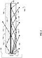
- FIG. 4 shows the adjustable edgelit luminaire 100 in a third example orientation and illuminated.
- the LES 130 is offset from the central position of the first orientation of FIG. 1 and, more particularly, is positioned lower than the LES 130 is positioned for the first and second orientations, of FIGs. 1 and 2 .
- the reflective component 140 keeps light passing through the upper lightguide 110 from entering the lower lightguide 120, and vice versa.
- the up/downlight ratio is lowered in proportion to the decrease in height of the LES 130 with respect to the lightguides 110, 120.
- the luminaire 100 is configured such that no light, very little light, or generally no light is provided by way of the upper lightguide 110 when the LES 130 is positioned at a minimum height with respect to the lightguides 110, 120.
- FIG. 5 illustrates an adjustable edgelit luminaire 500 according to a unitary-waveguide embodiment of the present technology.
- the luminaire 500 comprises a unitary lightguide component or body 502.
- the unitary lightguide body 502 includes a primary or base light-guide material 504 and, positioned (e.g., formed) therein, a reflective material 540.
- the reflective material 540 can be referred to by other names, such as a reflective component, and can be formed as a double-reflective sheet - i.e., reflective on opposing sides.
- the reflective component 540 includes any of reflective plastic, reflective metal (e.g., aluminum), and reflective paper. Surface material of the reflective component 140 can configured to promote specular or diffuse reflection.
- the base light-guide material 504 can be formed around any or all edges of the reflective material separates, such as to partially or completely surround the reflective material 540, the reflective material 540 generally separates the base light-guide material 504 into two portions - an upper portion 510 and a lower portion 520.
- the unitary lightguide body 502 includes a proximate edge 506 configured to allow light to pass from the LES 130 into the unitary lightguide body 502.
- Light is transmitted through the base light-guide material 504 of the unitary lightguide body 502, on either side of the reflective material 540, in generally the same manner provided with respect to the first example luminaire 100, of FIGs. 1-4 .
- the light is transmitted through the upper and/or lower portions 510, 520, with light impinging on the reflective material 540 reflecting accordingly, until all of the light is emitted, such as by way of the upper or lower surface 514, 524.
- a distal edge 507 of the light-guide body 502, opposite the proximate edge 506, can be configured like the distal edges 107 described above in connection with the first example luminaire 100 of FIG. 1 .
- the unitary lightguide body 502 can be formed to include the base light-guide material 504 positioned with the reflective material 540 in any of a variety of ways. In one embodiment, the unitary lightguide body 502 is formed a co-extrusion process by which the reflecting material 540 is formed within the base light-guide material 504.
- the unitary lightguide body 502 of FIG. 5 is positioned adjacent a light emitting source (LES) 130, such as an array of light emitting diodes, like the lightguide body 102 is positioned adjacent the LES 130 in FIG. 1 .
- LES light emitting source
- the luminaire 500 of FIG. 5 is illustrated having a generally horizontal layout, for controlling the uplight/downlight ratio, the luminaire 500 can be arranged at other angles, such as turned 90 degrees for controlling a right-light/left-light ratio, as also described with respect to the first example luminaire 100.
- the configuration, arrangement, and functions of the second example luminaire 500 of FIG. 5 can otherwise be similar or the same as the corresponding configuration, arrangement, and functions of the first example luminaire 100 described above in connection with FIGs. 1-4 , and so is not described further here.
Landscapes
- Physics & Mathematics (AREA)
- General Physics & Mathematics (AREA)
- Optics & Photonics (AREA)
- Engineering & Computer Science (AREA)
- General Engineering & Computer Science (AREA)
- Planar Illumination Modules (AREA)
Abstract
Description
- The present technology relates generally to adjustable light systems and, more particularly, to adjustable luminaires for selectively controlling uplight/downlight ratio from the luminaire.
- Preferred indoor lighting features depends on room characteristics such as size and color. Lighting is also affected by positioning of the luminaire(s), such as height of an edgelit luminaire in a room.
- Edgelit luminaires are configured to deliver light upward and downward at a single up/downlight ratio. These systems are thus limited to providing only one pre-defined direct/indirect lighting quality. An example ratio is fifty percent uplight, fifty percent downlight.
- A generally fifty/fifty (50%/50%), or half-half, up/down luminaire could produce ideal lighting for a particular room characteristic (e.g., size, or color) and luminaire positioning. If the room has other characteristics, and/or the luminaire must be positioned otherwise, such as for architectural or decorating reasons, the same luminaire will not produce ideal lighting.
- In some cases, re-positioning the luminaire can improve the lighting. This is not possible in all cases, though. When possible, the re-positioning may require a good amount of work (cost), and still the resulting position may not be preferred from an architectural or design standpoint.
- Another option, when a particular edgelit luminaire and luminaire positioning are not conducive for a particular room, is to obtain a different luminaire, with its added cost.
- A designer looking to use luminaires in each of twenty different rooms of a building, for instance, may need to purchase twenty different types of edgelit luminaires, which can be much more expensive than ordering the same type in bulk. Or a basic renovation of a room having edgelit luminaires can require purchase of new luminaires.
- Still another option, when a particular edgelit luminaire and luminaire positioning are not conducive for a particular room, is to use baffles or plates to block select amounts of up and/or down light from a fixed ratio luminaire to change the uplight/downlight ratio effectively. This arrangement, though, has negative impacts on optical efficiency. Less light is emitted from the system, for instance, representing wasted energy and usually less than idea lighting from the lumen power available for the fixture.
- Given the aforementioned deficiencies, there is a need for adjustable lighting systems capable of emitting light at any of various bi-directional light-emission ratios, depending on how the lighting systems are set.
- There is a need, for instance, for adjustable edgelit luminaires capable of providing various uplight/downlight ratios. The uplight/downlight ratio can be referred to by a variety of other terms, such as up/downlight ratio, up/down light ratio, up/down light-emission ratio, uplight/downlight light-emission ratio, or the like. The edgelit luminaire is configured to be mechanically adjusted to change the uplight/downlight ratio as desired.
- Generally, the ratio represents an amount of light that is emitted upward by the adjustable luminaire, such as toward a room ceiling, as compared to an amount of light that is emitted at the same time downward, toward a floor or ground.
- The edgelit luminaire is configured to be set selectively to provide light at any of two or more various uplight/downlight ratios. The different ratios are achieved by changing a relative positioning between a light-emitting structure (LES) of the luminaire and a reflective component. In some embodiments, the luminaire includes at least one of first and second - e.g., upper and lower - lightguides.
- In some cases the lightguides are arranged in the luminaire to maintain a static relative positioning with the reflective component. In these cases, the different ratios can be viewed as being achieved by changing a relative positioning between the light-emitting structure (LES) of the luminaire and the reflective component or between the light-emitting structure (LES) of the luminaire and the lightguide(s).
- While the present technology is described primarily with respect to an adjustable lateral-edgelit luminaire for selectively providing any of multiple uplight/downlight ratios, contemplated embodiments all ow edgelighting from angles other than from the side, and corresponding adjustments. Instead of being configured to adjust an uplight/downlight ratio, the system can be configured to adjust other bi-directional light-emission ratios, such as a left-light/right-light ratio.
- The technology can be implemented, for instance, in an adjustable toplit (or bottomlit) luminaire whereby the LES is movable (e.g., laterally movable) to control a right/left lighting ratio. While this embodiment is not shown in detail, it is can include any of the features described and shown herein with respect to lateral-edge lighting, except that the luminaire would be rotated ninety degrees clockwise or counterclockwise.
- Further features and advantages, as well as the structure and operation of various embodiments, are described in detail below with reference to the accompanying drawings. The technology is not limited to the specific embodiments described herein. Such embodiments are presented herein for illustrative purposes only. Additional embodiments will be apparent to persons skilled in the relevant art(s) based on the teachings contained herein.
- Exemplary embodiments may take form in various components and arrangements of components. Exemplary embodiments are illustrated in the accompanying drawings, throughout which like reference numerals may indicate corresponding or similar parts in the various figures. The drawings are only for purposes of illustrating preferred embodiments and are not to be construed as limiting the technology. Given the following enabling description of the drawings, novel aspects of the present technology will be evident to a person of ordinary skill in the art.
-
FIG.1 illustrates an adjustable edgelit luminaire according to a dual-waveguide embodiment of the present technology, in a first orientation. -
FIG. 2 shows the adjustable edgelit luminaire ofFIG. 1 in the first orientation and illumitated. -
FIG. 3 shows the adjustable edgelit luminaire ofFIG. 1 illuminated in a second orientation, providing a higher up/down light ratio. -
FIG. 4 shows the adjustable edgelit luminaire ofFIG. 1 illuminated in a third orientation, providing a lower up/downlight ratio. -
FIG. 5 illustrates an adjustable edgelit luminaire according to a unitary-waveguide embodiment of the present technology. - While exemplary embodiments are described herein with illustrative embodiments for particular implementations, it should be understood that the technology is not limited thereto. Those skilled in the art with access to the teachings provided herein will recognize additional modifications, applications, and embodiments within the scope thereof, and additional fields in which the adjustable luminaire described herein would be of significant utility.
- References herein to how a feature is arranged can refer to, but are not limited to, how the features is positioned with respect to other features. References herein to how a feature is configured can refer to, but are not limited to, how the feature is sized, shaped, and/or material of the feature. For simplicity, the term configured can be used to refer to both the configuration and arrangement described above in this paragraph.
-
FIG.1 is an illustration of an exampleadjustable edgelit luminaire 100. While anedgelit luminaire 100 is shown for teaching purposes, the present technology is not limited for implementation with edgelight luminaires. - The
luminaire 100 includes a light-guide component orbody 102. The light-guide body 102 includes an upper lightguide, or waveguide, 110, and a lower lightguide, orwaveguide 120. Thelightguides - The
upper lightguide 110 can be referred to by other names, such as uplight, and thelower lightguide 120 can be referred to by other names such as downlight. - The
lightguides lightguides - The light-
guide body 102 includes proximate edges 106 (an upper one, of theupper lightguide 110, and a lower one, of the lower lightguide 120) configured to allow light to pass from the LES 130 into thelightguides FIGs. 2-4 , the light is transmitted through one or both of thelightguides length 108 of thebody 102, until it is emitted from theluminaire 100 by way of anupper surface 114, of theupper lightguide 110, or alower surface 124, of thelower lightguide 120. -
Distal edges 107 of the light-guide body 102 (one of theupper lightguide 110 and one of the lower lightguide 120), opposite theproximate edges 106, can be configured in any of a variety of ways to affect as desired any light reaching thedistal edge 107. Thedistal edge 107 can be opaque, such as by being painted, taped, or capped to inhibit light emission by way of the distal edge, or can be configured to let all or some of light reaching thedistal edge 107 passing straight through. - The
surfaces luminaire 100. Thesurfaces reference numeral 115 inFIG. 1 . Or one or both of the opposing light-emitting surfaces can be generally smooth, as shown for analogous light-emittingsurfaces FIG. 5 . - The light-
guide body 102 also includes anintermediate component 140 having two opposingreflective sides intermediate component 140 can be referred to by a variety of names, such as a separator, reflector, reflecting wall, reflecting interface, reflective sheet, reflecting component, interface, or sheet, reflective component, the like, or other. Thepart 140 will be referred to primarily as a reflective component herein. - The
reflective component 140 is configured and arranged in theluminaire 100 to affect light impinging on thereflective component 140 in one or more desired ways. In some embodiments, thereflective component 140 is reflective and shaped as a sheet, panel, film, or the like. - Generally, the
reflective component 140 is configured and arranged between thelightguides LES 130 and passing through one of thelightguides other lightguide lightguide other lightguide - The
reflective component 140 can include any suitable material and shape for reflecting light as desired. Thereflective component 140 can be double-reflective - i.e., reflective at each opposing sides of thecomponent 140. In some embodiments, thereflective component 140 includes any of reflective plastic, reflective metal (e.g., aluminum), and reflective paper. Surface material of thereflective component 140 can configured to promote specular or diffuse reflection. - In various contemplated embodiments (not shown in detail), the
luminaire 100 does not include one or both of thelightguides - In various contemplated embodiments (not shown in detail), the
LES 130 is not an edgelight, but rather positioned at a location other than an extreme edge of the reflector. The light can be positioned between portions of the reflector, for instance, such as through a hole in the reflector. - The
luminaire 100 is shown in a first orientation inFIG. 1 . The first orientation may be referred to by other names such as a first state, a standard state or orientation, a home state or orientation, the like or other. In the first, or home, orientation, theLES 130 is centrally positioned with respect to the up and downlightguides - Positioning of the
LES 130 with respect to thelightguides luminaire 100. The uplight/downlight ratio represents an amount of light, or lumens, being delivered by an upper portion, corresponding to theupper lightguide 110, of theluminaire 100 as compared to an amount of light, or lumens, being delivered by a lower portion, corresponding to thelower lightguide 120, of theluminaire 100. - The
luminaire 100 provides light at a higher uplight/downlight ratio as more light is delivered by way of theupper lightguide 110 with respect to the amount of light being delivered by way of thelower lightguide 120. And vice versa, - i.e., theluminaire 100 provides light at a lower uplight/downlight ratio when less light is delivered by way of theupper lightguide 110 with respect to the amount of light being delivered by way of thelower lightguide 120. - It is contemplated that the amount of light being delivered by way of the upper and
lower lightguides luminaire 100 provides light at a lower downlight/uplight ratio as more light is delivered by way of theupper lightguide 110 with respect to the amount of light being delivered by way of thelower lightguide 120. And vice versa, - i.e., theluminaire 100 provides light at a higher downlight/uplight ratio when less light is delivered by way of theupper lightguide 110 with respect to the amount of light being delivered by way of thelower lightguide 120. - While either of the ratios (up/downlight ratio, or down/uplight ratio) can be used, by designers or users of the
luminaire 100, the uplight/downlight ratio is referred to primarily herein for simplicity. - The
luminaire 100 comprises amovable positioning apparatus 150 configured and arranged in the system to change a relative positioning between theLES 130 and thereflective component 140. In various embodiments, themovable positioning apparatus 150 is connected to theLES 130 for moving theLES 130 to change the relative positioning between theLES 130 and thelightguides positioning apparatus 150 is connected to at least one of thelightguides lightguides LES 130 and thelightguides - Positioning of the
LES 130 with respect to thelightguides positioning apparatus 150, shown schematically inFIGs. 1-3 . Thepositioning apparatus 150 can have any of a wide variety of configurations without departing from the scope of the present technology. - The
positioning apparatus 150 is in some embodiments configured to be electrically actuated. Thepositioning apparatus 150 can be connected to a switch, button, or computing controller that a remote or local computing system or person can trigger desired movement of thepositioning apparatus 150 to change to the uplight/downlight ratio as desired. - In various embodiments (not shown in great detail to simplify the disclosure), the
positioning apparatus 150 is arranged and connected to theLES 130 to move the LES generally linearly - e.g., up/down, left/right, or other bi-direction. The motion is indicated generally and schematically inFIG. 1 byreference numeral 160. - The arrangement can include, for instance, a rack-and-pinion arrangement whereby the positioning apparatus comprises a pinion, or gear, that when turned pushes the
LES 130, comprising a rack, upward or downward accordingly. - Or the arrangement can include a slide. The
positioning apparatus 150 can include a guide track connected slidably with a rail or slide connected to theLES 130 orreflective component 140 to change a relative positioning between theLES 130 andreflective component 140. Or thepositioning apparatus 150 can include the slide and the guide track can be connected to theLES 130 orreflective component 140 for setting a relative positioning between theLES 130 andreflective component 140 as desired. - In another contemplated embodiment (not shown in detail to simplify the disclosure), the
positioning apparatus 150 comprises an incremental-position locking mechanism, such as by including a plurality of positioning magnets, hooks, slots, orifices, recepticales or other elements capable of connecting temperarily to a mating element connected to theLES 130. The positioning elements can be vertically arranged for instance, such that theLES 130 can be positioned at any of multiple corresponding heights by connecting the mating element of theLES 130 to the positioning elements of thepositioning apparatus 150. - In still another contemplated embodiment (not shown in great detail), like the last embodiment described, the
positioning apparatus 150 comprises the mating element and theLES 130 is connected to a plurality of positioning elements. The positioning elements are vertically arranged with respect to the LES such that theLES 130 can be positioned at any of multiple corresponding heights by connecting the mating element of thepositioning apparatus 150 to the positioning elements of theLES 130. - In another contemplated embodiment (not shown in great detail), similar in ways to the last embodiment described, the
positioning apparatus 150 comprises the mating element and theLES 130 is connected to a plurality of positioning elements. The positioning elements are vertically arranged with respect to the LES such that theLES 130 can be positioned at any of multiple corresponding heights by connecting the mating element of thepositioning apparatus 150 to the positioning elements of theLES 130. - The arrangement can be structured so that the
LES 130 can be moved to any of multiple pre-set heights. The pre-set heights can correspond, for instance, to selectable slots. - And/or the arrangement can be structure so that the
LES 130 can be moved to virtually any position between a maximum (e.g., highest) position, or height, and a minimum (e.g., lowest) position or height. In this case, then, theLES 130 can be moved to, effectively, an infinite number of lighting positions - i.e., infinite different up/downlight ratios. - In a contemplated embodiment, the
luminaire 100 is configured so that relative positioning between theLES 130 and thelightguides lightguides - In various embodiments (not shown in detail), the
positioning apparatus 150 is arranged and connected to theLES 130 to rotate theLES 130. - In various embodiments, for example, the
LES 130 includes various lights in various parts to effect different up/downlight ratios, depending on which parts are positioned where with respect to thereflective component 140. - For instance, more lighting element(s) (e.g., more LED rows of an LED board, or a larger array, providing, for instance, 70% of total LES light) can be positioned toward a top of the
LES 130 and less (providing, for instance, the other 30% of total LES light) toward a bottom of theLES 130. - In contemplated embodiments, along with having more or less lighting elements, or instead of having more or less lighting elements, the
LES 130 comprises other distinguishing lighting features from part to part, such as by having stronger and weaker lighting element(s) in various parts, or having lighting elements of different hues or colors in various parts. - The
LES 130 andpositioning apparatus 150 are configured and arranged (e.g., connected) so that the orientation of theLES 130 can be rotated. The motion is indicated generally and schematically inFIG. 1 byreference numeral 170. While thearrow 170 is shown bending slightly left and right, the rotation need not include that trajectory. In embodiments, it is preferred that the rotation indicated by thearrow 170 be made while keeping theLES 130 in the same plane that it is shown in. - The
LES 130 can be configured and arranged to be rotated 180 degrees, for instance, such as by the LES being flipped with respect to thelightguides LES 130, adjacent thelower lightguide 120, and another, different part (having, e.g., less LEDs) will be positioned higher on theLES 130, adjacent theupper lightguide 110. - In another contemplated embodiment (not shown in detail), similar in ways to the last described embodiment, in which the
LES 130 comprises two sections having different light-emitting characteristics, theLES 130 comprises three or more various sections having different light-emitting characteristics. TheLES 130 can have a dial formation, for instance, and be arranged adjacent thelightguides positioning apparatus 150 so that rotating thepositioning apparatus 150 to one of multiple pre-set positions turns theLES 130 to corresponding pre-set positions. - In one embodiment, the movable apparatus is configured to be readily removed (e.g., snapped off, or by pulling magnets apart) from a first position at the
luminaire 100 and readly returned to a second position (e.g., by snap or magnet), such as to a position being 180 degrees distinct from the first position. - At each position, different amounts of light of are provided through the
upper lightguide 110 and thelower lightguide 120, resulting thus in various corresponding uplight/downlight ratios. - In another contemplated embodiment, the
LES 130 has a varying distribution of lighting characteristics and connected to amovable positioning apparatus 150 so that moving (e.g., rotating) thepositioning apparatus 150 moves theLES 130 to a corresponding position, providing a corresponding amount and/or type of light to theupper lightguide 110 and a distinct amount of light to the lower lightguide. - While two
primary LES 130 parts are described primarily, functioning in one of two positions being 180 degrees apart, theLES 130 can have more than two areas, such as by having four areas whereby two are used at a time depending on user selective positioning of theLES 130 with respect to thereflective component 140 in any of four relative positionings being 90 degrees apart. - In some implementations, the arrangement is structured (e.g., with selectable slots) so that the
LES 130 can be rotated to any of multiple pre-set positions. The positions can be marked by slots, protrusions, depressions, any suitable structure on theLES 130 andpositioning apparatus 150 for keeping the LES in place with respect to thelightguides LES 130 is moved again. - In another implementation, the
LES 130 can be rotated to any position between points (e.g., any position around a 360 degree range), so that an infinite number of lighting combinations - i.e., infinite different up/downlight ratios - can be achieved by positioning theLES 130 in any of infinite positions in the range. -
FIG. 2 shows theadjustable edgelit luminaire 100 in the first orientation and illuminated. Light travelling through theupper lightguide 110 is labeled byreference numeral 112. Light travelling through thelower lightguide 120 is labeled byreference numeral 122. - As shown, with the
LES 130 positioned generally centrally with respect to the upper andlower lightguides LES 130 will propagate through theupper lightguide 110 and approximately half will propagate through thelower lightguide 120. - As also shown in
FIG. 2 , thereflective component 140 keeps light passing through theupper lightguide 110 from entering thelower lightguide 120, and vice versa. - For implementations in which generally equal amounts of lumen is desired from the top and bottom of the luminaire, the
adjustable edgelit system 100 is positioned in the first orientation ofFIGs. 1 and2 . -
FIG. 3 shows theadjustable edgelit luminaire 100 in a second example orientation and illuminated. For the second orientation, theLES 130 is offset from the central position of the first orientation ofFIG. 1 and, more particularly, is positioned higher than theLES 130 is positioned for the first orientation. - As shown schematically in
FIG. 3 , with theLES 130 positioned higher, more light from theLES 130 enters theupper lightguide 110 than enters thelower lightguide 120. And again, thereflective component 140 keeps light passing through theupper lightguide 110 from entering thelower lightguide 120, and vice versa. - The up/downlight ratio is increased in proportion to the increase in height of the
LES 130 with respect to thelightguides - In some arrangements, the
luminaire 100 is configured such that no light, very little light, or generally no light is provided by way of thelower lightguide 120 when theLES 130 is positioned at a maximum height with respect to thelightguides -
FIG. 4 shows theadjustable edgelit luminaire 100 in a third example orientation and illuminated. For the third orientation, theLES 130 is offset from the central position of the first orientation ofFIG. 1 and, more particularly, is positioned lower than theLES 130 is positioned for the first and second orientations, ofFIGs. 1 and2 . - As shown schematically in
FIG. 4 , with theLES 130 positioned lower, more light from theLES 130 enters thelower lightguide 120 than enters theupper lightguide 110. And again, thereflective component 140 keeps light passing through theupper lightguide 110 from entering thelower lightguide 120, and vice versa. - The up/downlight ratio is lowered in proportion to the decrease in height of the
LES 130 with respect to thelightguides - In some arrangements, the
luminaire 100 is configured such that no light, very little light, or generally no light is provided by way of theupper lightguide 110 when theLES 130 is positioned at a minimum height with respect to thelightguides -
FIG. 5 illustrates anadjustable edgelit luminaire 500 according to a unitary-waveguide embodiment of the present technology. - The
luminaire 500 comprises a unitary lightguide component orbody 502. Theunitary lightguide body 502 includes a primary or base light-guide material 504 and, positioned (e.g., formed) therein, areflective material 540. - The
reflective material 540 can be referred to by other names, such as a reflective component, and can be formed as a double-reflective sheet - i.e., reflective on opposing sides. In some embodiments, thereflective component 540 includes any of reflective plastic, reflective metal (e.g., aluminum), and reflective paper. Surface material of thereflective component 140 can configured to promote specular or diffuse reflection. - While the base light-
guide material 504 can be formed around any or all edges of the reflective material separates, such as to partially or completely surround thereflective material 540, thereflective material 540 generally separates the base light-guide material 504 into two portions - anupper portion 510 and alower portion 520. - The
unitary lightguide body 502 includes aproximate edge 506 configured to allow light to pass from theLES 130 into theunitary lightguide body 502. Light is transmitted through the base light-guide material 504 of theunitary lightguide body 502, on either side of thereflective material 540, in generally the same manner provided with respect to thefirst example luminaire 100, ofFIGs. 1-4 . For instance, the light is transmitted through the upper and/orlower portions reflective material 540 reflecting accordingly, until all of the light is emitted, such as by way of the upper orlower surface - A
distal edge 507 of the light-guide body 502, opposite theproximate edge 506, can be configured like thedistal edges 107 described above in connection with thefirst example luminaire 100 ofFIG. 1 . - The
unitary lightguide body 502 can be formed to include the base light-guide material 504 positioned with thereflective material 540 in any of a variety of ways. In one embodiment, theunitary lightguide body 502 is formed a co-extrusion process by which the reflectingmaterial 540 is formed within the base light-guide material 504. - The
unitary lightguide body 502 ofFIG. 5 is positioned adjacent a light emitting source (LES) 130, such as an array of light emitting diodes, like thelightguide body 102 is positioned adjacent theLES 130 inFIG. 1 . - While the
luminaire 500 ofFIG. 5 is illustrated having a generally horizontal layout, for controlling the uplight/downlight ratio, theluminaire 500 can be arranged at other angles, such as turned 90 degrees for controlling a right-light/left-light ratio, as also described with respect to thefirst example luminaire 100. - The configuration, arrangement, and functions of the
second example luminaire 500 ofFIG. 5 can otherwise be similar or the same as the corresponding configuration, arrangement, and functions of thefirst example luminaire 100 described above in connection withFIGs. 1-4 , and so is not described further here. - Alternative embodiments, examples, and modifications that would still be encompassed by the technology may be made by those skilled in the art, particularly in light of the foregoing teachings. Further, it should be understood that the terminology used to describe the technology is intended to be in the nature of words of description rather than of limitation.
- Those skilled in the art will also appreciate that various adaptations and modifications of the preferred and alternative embodiments described above can be configured without departing from the scope and spirit of the technology. Therefore, it is to be understood that, within the scope of the appended claims, the technology may be practiced other than as specifically described herein. For completeness, various aspects of the invention are set out in the following numbered clauses:
- 1. An adjustable lighting system, configured to emit light at any of various bi-directional light-emission ratios, comprising:
- a reflective component;
- a light source positioned adjacent the reflective component; and
- a movable positioning apparatus connected to the light source or the reflective component;
- wherein the movable positioning apparatus is configured to, when moved, change a relative positioning between the light source and the reflective component.
- 2. The adjustable lighting system of clause 1 wherein:
- the reflective component is positioned laterally adjacent at least a portion of the light source;
- and the movable positioning apparatus is configured and arranged in the adjustable lighting system to, when moved, change a relative vertical positioning between the light source and
- the reflective component, for the adjustable lighting system to emit light at a different one of the various bi-directional light-emission ratios being up/down light-emission ratios.
- 3. The adjustable lighting system of clause 2 wherein the movable positioning apparatus comprises an incremental-position locking mechanism, a slide mechanism, or a rack-and-pinion mechanism, configured to move the light source or the reflective component vertically to change the relative vertical positioning between the light source and the reflective component for the adjustable lighting system to emit light at a different one of the various up/down light-emission ratios.
- 4. The adjustable lighting system of clause 1 wherein:
- the reflective component is positioned vertically adjacent at least a portion of the light source;
- and the movable positioning apparatus is configured and arranged in the adjustable lighting system to, when moved, change a relative lateral positioning between the light source and the reflective component, for the adjustable lighting system to emit light at a different one of the various bi-directional light-emission ratios being various left/right light-emission ratios.
- 5.The adjustable lighting system of clause 1 wherein the movable positioning apparatus is configured and arranged in the adjustable lighting system to, when moved, change a relative rotational positioning between the light source and the reflective component, for the adjustable lighting system to emit light at a different one of the various bi-directional light-emission ratios.
- 6.The adjustable lighting system of clause 1 further comprising a lightguide component having a first emitting surface and a second emitting surface opposite the first emitting surface, wherein the reflective component is positioned between the first and second emitting surfaces and the lightguide is positioned adjacent the light source and configured to, in operation of the adjustable lighting system, transmit received light out of the adjustable lighting system by way of the first emitting surface and the second emitting surface.
- 7. The adjustable lighting system of clause 6 further comprising:
- a first lightguide comprising the first light-emitting surface and a second internal surface opposite the first light-emitting surface; and
- a second lightguide comprising the second light-emitting surface and a second internal surface opposite the second light-emitting surface;
- wherein the reflective component is positioned between the first and second internal surfaces.
- 8. The adjustable lighting system of clause 6 wherein: the light source is an edgelight; and the lightguide has a proximate edge positioned adjacent the edgelight to, in operation of the adjustable lighting system, transmit light from the edgelight out of the adjustable lighting system by way of the first emitting surface and the second emitting surface.
- 9. An adjustable lighting system, configured to emit light at any of various bi-directional light-emission ratios, comprising:
- a first lightguide having a first emitting surface opposite a first internal surface, and being configured to transmit light received at the first lightguide out of the adjustable lighting system by way of the upper emitting surface;
- a second lightguide having a second emitting surface opposite a second internal surface, and
- configured to transmit light received at the second lightguide out of the adjustable lighting system by way of the lower emitting surface;
- a light source;
- a reflective component positioned adjacent the light source and between the first and second internal surfaces to block light transmitting through the first lightguide from passing into the second lightguide and light transmitting through the second lightguide from passing into the first lightguide; and
- a movable positioning apparatus connected to the light source or the reflective component;
- wherein the movable positioning apparatus is configured to, when moved, change a relative positioning between the light source and the reflective component.
- 10. The adjustable lighting system of clause 9 wherein: the reflective component is positioned laterally adjacent at least a portion of the light source; and the various bi-directional light-emission ratios include various up/down light-emission ratios.
- 11. The adjustable lighting system of clause 9 wherein:
- the reflective component is positioned vertically adjacent at least a portion of the light source;
- and the various bi-directional light-emission ratios include left/right light-emission ratios.
- 12.The adjustable lighting system of clause 9 wherein the movable positioning apparatus is configured and arranged in the adjustable lighting system to, when moved, change a relative linear positioning between the light source and the reflective component, for the adjustable lighting system to emit light at a different one of the various bi-directional light-emission ratios.
- 13.The adjustable lighting system of clause 12 wherein the light source comprises plurality of lighting sections, and each one of the lighting sections can be positioned adjacent the reflective component based on the relative linear positioning.
- 14.The adjustable lighting system of clause 9 wherein the movable positioning apparatus is configured and arranged in the adjustable lighting system to, when moved, change a relative rotational positioning between the light source and the reflective component, for the adjustable lighting system to emit light at a different one of the various bi-directional light-emission ratios.
- 15.The adjustable lighting system of clause 14 wherein the light source comprises plurality of lighting sections, and each one of the lighting sections can be positioned adjacent the reflective component based on the relative rotational positioning.
- 16. An adjustable lighting system, configured to emit light at any of various bi-directional light-emission ratios, comprising:
- a unitary lightguide body including a light-guide material, a first light-emitting surface opposite a second light-emitting surface, and a reflective material positioned between the first and second light-emitting surfaces;
- a light source arranged adjacent the single lightguide; and
- a movable positioning apparatus connected to the light source or the unitary lightguide body;
- wherein the movable positioning apparatus is configured to, when moved, change a relative positioning between the light source and the reflective component, to produce a different one of the various bi-directional light-emission ratios.
- 17. The adjustable lighting system of clause 16 wherein:
- the reflective component is positioned laterally adjacent at least a portion of the light source;
- and the bi-directional light-emission ratios include various up/down light-emission ratios.
- 18. The adjustable lighting system of clause 16 wherein:
- the reflective component is positioned vertically adjacent at least a portion of the light source;
- and the various bi-directional light-emission ratios include various left/right light-emission ratios.
- 19.The adjustable lighting system of clause 16 wherein the movable positioning apparatus is configured and arranged in the adjustable lighting system to, when moved, change the relative positioning being a relative rotational positioning between the light source and the reflective component, to produce the different one of the various bi-directional light-emission ratios.
- 20. The adjustable lighting system of clause 16 wherein the lightguide comprises multiple rows of light-emitting diodes.
Claims (15)
- An adjustable lighting system, configured to emit light at any of various bi-directional light-emission ratios, comprising:a reflective component;a light source positioned adjacent the reflective component; anda movable positioning apparatus connected to the light source or the reflective component;wherein the movable positioning apparatus is configured to, when moved, change a relative positioning between the light source and the reflective component.
- The adjustable lighting system of claim 1 wherein:the reflective component is positioned laterally adjacent at least a portion of the light source; andthe movable positioning apparatus is configured and arranged in the adjustable lighting system to, when moved, change a relative vertical positioning between the light source and the reflective component, for the adjustable lighting system to emit light at a different one of the various bi-directional light-emission ratios being up/down light-emission ratios.
- The adjustable lighting system of claim 2 wherein the movable positioning apparatus comprises an incremental-position locking mechanism, a slide mechanism, or a rack-and-pinion mechanism, configured to move the light source or the reflective component vertically to change the relative vertical positioning between the light source and the reflective component for the adjustable lighting system to emit light at a different one of the various up/down light-emission ratios.
- The adjustable lighting system of claim 1 wherein:the reflective component is positioned vertically adjacent at least a portion of the light source; andthe movable positioning apparatus is configured and arranged in the adjustable lighting system to, when moved, change a relative lateral positioning between the light source and the reflective component, for the adjustable lighting system to emit light at a different one of the various bi-directional light-emission ratios being various left/right light-emission ratios.
- The adjustable lighting system of claim 1 wherein the movable positioning apparatus is configured and arranged in the adjustable lighting system to, when moved, change a relative rotational positioning between the light source and the reflective component, for the adjustable lighting system to emit light at a different one of the various bi-directional light-emission ratios.
- The adjustable lighting system of claim 1 further comprising a lightguide component having a first emitting surface and a second emitting surface opposite the first emitting surface, wherein the reflective component is positioned between the first and second emitting surfaces and the lightguide is positioned adjacent the light source and configured to, in operation of the adjustable lighting system, transmit received light out of the adjustable lighting system by way of the first emitting surface and the second emitting surface.
- The adjustable lighting system of claim 6 further comprising:a first lightguide comprising the first light-emitting surface and a second internal surface opposite the first light-emitting surface; anda second lightguide comprising the second light-emitting surface and a second internal surface opposite the second light-emitting surface;wherein the reflective component is positioned between the first and second internal surfaces.
- The adjustable lighting system of claim 6 wherein:the light source is an edgelight; andthe lightguide has a proximate edge positioned adjacent the edgelight to, in operation of the adjustable lighting system, transmit light from the edgelight out of the adjustable lighting system by way of the first emitting surface and the second emitting surface.
- An adjustable lighting system, configured to emit light at any of various bi-directional light-emission ratios, comprising:a first lightguide having a first emitting surface opposite a first internal surface, and being configured to transmit light received at the first lightguide out of the adjustable lighting system by way of the upper emitting surface;a second lightguide having a second emitting surface opposite a second internal surface, and configured to transmit light received at the second lightguide out of the adjustable lighting system by way of the lower emitting surface;a light source;a reflective component positioned adjacent the light source and between the first and second internal surfaces to block light transmitting through the first lightguide from passing into the second lightguide and light transmitting through the second lightguide from passing into the first lightguide; anda movable positioning apparatus connected to the light source or the reflective component;wherein the movable positioning apparatus is configured to, when moved, change a relative positioning between the light source and the reflective component.
- The adjustable lighting system of claim 9 wherein:the reflective component is positioned laterally adjacent at least a portion of the light source; andthe various bi-directional light-emission ratios include various up/down light-emission ratios.
- The adjustable lighting system of claim 9 wherein:the reflective component is positioned vertically adjacent at least a portion of the light source; andthe various bi-directional light-emission ratios include left/right light-emission ratios.
- The adjustable lighting system of claim 9 wherein the movable positioning apparatus is configured and arranged in the adjustable lighting system to, when moved, change a relative linear positioning between the light source and the reflective component, for the adjustable lighting system to emit light at a different one of the various bi-directional light-emission ratios.
- The adjustable lighting system of claim 12 wherein the light source comprises plurality of lighting sections, and each one of the lighting sections can be positioned adjacent the reflective component based on the relative linear positioning.
- The adjustable lighting system of claim 9 wherein the movable positioning apparatus is configured and arranged in the adjustable lighting system to, when moved, change a relative rotational positioning between the light source and the reflective component, for the adjustable lighting system to emit light at a different one of the various bi-directional light-emission ratios.
- The adjustable lighting system of claim 14 wherein the light source comprises plurality of lighting sections, and each one of the lighting sections can be positioned adjacent the reflective component based on the relative rotational positioning.
Applications Claiming Priority (1)
| Application Number | Priority Date | Filing Date | Title |
|---|---|---|---|
| US14/956,582 US9869455B2 (en) | 2015-12-02 | 2015-12-02 | Adjustable luminaire for selectively controlling uplight/downlight ratio |
Publications (1)
| Publication Number | Publication Date |
|---|---|
| EP3176498A1 true EP3176498A1 (en) | 2017-06-07 |
Family
ID=57442486
Family Applications (1)
| Application Number | Title | Priority Date | Filing Date |
|---|---|---|---|
| EP16200845.2A Withdrawn EP3176498A1 (en) | 2015-12-02 | 2016-11-28 | Adjustable luminaire for selectively controlling uplight/downlight ratio |
Country Status (2)
| Country | Link |
|---|---|
| US (1) | US9869455B2 (en) |
| EP (1) | EP3176498A1 (en) |
Cited By (1)
| Publication number | Priority date | Publication date | Assignee | Title |
|---|---|---|---|---|
| EP3591281A1 (en) * | 2018-07-04 | 2020-01-08 | Herbert Waldmann GmbH & Co. KG | Interior light |
Families Citing this family (6)
| Publication number | Priority date | Publication date | Assignee | Title |
|---|---|---|---|---|
| US10386571B1 (en) * | 2015-02-26 | 2019-08-20 | Cooper Technologies Company | Apparatus for coupling light into lightguides |
| USD810348S1 (en) | 2016-02-26 | 2018-02-13 | Cooper Technologies Company | Dual lightguide light fixture |
| US20180335667A1 (en) * | 2017-05-19 | 2018-11-22 | Innolux Corporation | Backlight module and display device containing the same |
| DE202020100855U1 (en) * | 2020-02-18 | 2021-05-25 | Zumtobel Lighting Gmbh | Surface luminaire with direct and indirect light emission |
| US11668443B2 (en) | 2021-05-17 | 2023-06-06 | Lsi Industries, Inc. | Luminaire uplight device and related methods |
| US20240044461A1 (en) * | 2022-08-04 | 2024-02-08 | Earth Lighting LLC | Bi-directional tubular led light engine |
Citations (3)
| Publication number | Priority date | Publication date | Assignee | Title |
|---|---|---|---|---|
| US4949489A (en) * | 1987-12-28 | 1990-08-21 | Rudell Elliot A | Edge-lit multiple image display device |
| EP2469313A1 (en) * | 2010-12-21 | 2012-06-27 | LG Innotek Co., Ltd. | Lighting module |
| US20120236590A1 (en) * | 2011-03-17 | 2012-09-20 | Parker Jeffery R | Lighting assembly with adjustable light output |
Family Cites Families (8)
| Publication number | Priority date | Publication date | Assignee | Title |
|---|---|---|---|---|
| US6478454B1 (en) | 2000-08-31 | 2002-11-12 | Genlyte Thomas Group Llc | Adjustable uplight luminaire with an adjustable reflector |
| US7329026B1 (en) | 2006-11-13 | 2008-02-12 | Jeffery John Hayman | Lighting fixture with smooth adjustable beam width |
| US8794812B2 (en) | 2009-05-01 | 2014-08-05 | Abl Ip Holding Llc | Light emitting devices and applications thereof |
| BR112012005509A2 (en) | 2009-09-15 | 2019-05-21 | Koninl Philips Electronics Nv | light emitting device and luminaire |
| US9028120B2 (en) | 2011-08-08 | 2015-05-12 | Quarkstar Llc | Illumination devices including multiple light emitting elements |
| CN104755832B (en) | 2012-09-13 | 2018-12-21 | 夸克星有限责任公司 | Lighting systems providing direct and indirect lighting |
| CN102913816B (en) * | 2012-09-28 | 2015-11-11 | 京东方科技集团股份有限公司 | Side-light backlight module and liquid crystal indicator |
| US9599765B2 (en) * | 2013-03-15 | 2017-03-21 | Blackberry Limited | System and method for displaying visual notifications on an electronic device |
-
2015
- 2015-12-02 US US14/956,582 patent/US9869455B2/en not_active Expired - Fee Related
-
2016
- 2016-11-28 EP EP16200845.2A patent/EP3176498A1/en not_active Withdrawn
Patent Citations (3)
| Publication number | Priority date | Publication date | Assignee | Title |
|---|---|---|---|---|
| US4949489A (en) * | 1987-12-28 | 1990-08-21 | Rudell Elliot A | Edge-lit multiple image display device |
| EP2469313A1 (en) * | 2010-12-21 | 2012-06-27 | LG Innotek Co., Ltd. | Lighting module |
| US20120236590A1 (en) * | 2011-03-17 | 2012-09-20 | Parker Jeffery R | Lighting assembly with adjustable light output |
Cited By (1)
| Publication number | Priority date | Publication date | Assignee | Title |
|---|---|---|---|---|
| EP3591281A1 (en) * | 2018-07-04 | 2020-01-08 | Herbert Waldmann GmbH & Co. KG | Interior light |
Also Published As
| Publication number | Publication date |
|---|---|
| US20170159913A1 (en) | 2017-06-08 |
| US9869455B2 (en) | 2018-01-16 |
Similar Documents
| Publication | Publication Date | Title |
|---|---|---|
| US9869455B2 (en) | Adjustable luminaire for selectively controlling uplight/downlight ratio | |
| US10739509B2 (en) | Optical waveguide bodies and luminaires utilizing same | |
| US10416377B2 (en) | Luminaire with controllable light emission | |
| US10317608B2 (en) | Luminaires utilizing optical waveguide | |
| US11536894B2 (en) | Modular waveguides and fixtures utilizing same | |
| EP2135003B1 (en) | Tiled lighting device | |
| US10422939B2 (en) | Waveguide having unidrectional illuminance | |
| US20050122742A1 (en) | Led lamp tube | |
| US9404646B2 (en) | Lighting system with angled LED arrays | |
| US20140347885A1 (en) | Optical Waveguide Bodies and Luminaires Utilizing Same | |
| CN105102889A (en) | Optical waveguide body and luminous body using the optical waveguide body | |
| US20240210609A1 (en) | Lighting fixture with waveguide | |
| US10670225B2 (en) | Sparkle effect lighting device | |
| US11408572B2 (en) | Luminaires utilizing optical waveguide | |
| US10823367B1 (en) | Modular LED light fixture with spaced diffuser | |
| US20250084980A1 (en) | Lighting apparatus | |
| US11460170B2 (en) | Luminaire with electrochromic film reflector | |
| CN203363720U (en) | LED panel light allowing colors and temperatures to be intelligently adjustable | |
| CN103883950A (en) | Starmoon ceiling-mounted lamp | |
| CN202532227U (en) | Double-side light-emitting type lamp structure | |
| EP3705778A1 (en) | Lighting apparatus with screens and method | |
| US11137120B2 (en) | Modular lighting system | |
| US20100110658A1 (en) | Semi-direct solid state lighting fixture and distribution | |
| EP2644987B1 (en) | Lighting device and lighting method | |
| CN210624230U (en) | A kind of multi-angle transformation structure and linear lamp |
Legal Events
| Date | Code | Title | Description |
|---|---|---|---|
| AK | Designated contracting states |
Kind code of ref document: A1 Designated state(s): AL AT BE BG CH CY CZ DE DK EE ES FI FR GB GR HR HU IE IS IT LI LT LU LV MC MK MT NL NO PL PT RO RS SE SI SK SM TR |
|
| AX | Request for extension of the european patent |
Extension state: BA ME |
|
| PUAI | Public reference made under article 153(3) epc to a published international application that has entered the european phase |
Free format text: ORIGINAL CODE: 0009012 |
|
| STAA | Information on the status of an ep patent application or granted ep patent |
Free format text: STATUS: THE APPLICATION HAS BEEN PUBLISHED |
|
| STAA | Information on the status of an ep patent application or granted ep patent |
Free format text: STATUS: REQUEST FOR EXAMINATION WAS MADE |
|
| 17P | Request for examination filed |
Effective date: 20171207 |
|
| RBV | Designated contracting states (corrected) |
Designated state(s): AL AT BE BG CH CY CZ DE DK EE ES FI FR GB GR HR HU IE IS IT LI LT LU LV MC MK MT NL NO PL PT RO RS SE SI SK SM TR |
|
| STAA | Information on the status of an ep patent application or granted ep patent |
Free format text: STATUS: THE APPLICATION IS DEEMED TO BE WITHDRAWN |
|
| 18D | Application deemed to be withdrawn |
Effective date: 20200603 |