EP3176459A1 - Pad for a bicycle disc brake and disc brake comprising such a pad - Google Patents
Pad for a bicycle disc brake and disc brake comprising such a pad Download PDFInfo
- Publication number
- EP3176459A1 EP3176459A1 EP16201773.5A EP16201773A EP3176459A1 EP 3176459 A1 EP3176459 A1 EP 3176459A1 EP 16201773 A EP16201773 A EP 16201773A EP 3176459 A1 EP3176459 A1 EP 3176459A1
- Authority
- EP
- European Patent Office
- Prior art keywords
- pad
- friction
- wearing
- disc brake
- wearing material
- Prior art date
- Legal status (The legal status is an assumption and is not a legal conclusion. Google has not performed a legal analysis and makes no representation as to the accuracy of the status listed.)
- Granted
Links
Images





Classifications
-
- F—MECHANICAL ENGINEERING; LIGHTING; HEATING; WEAPONS; BLASTING
- F16—ENGINEERING ELEMENTS AND UNITS; GENERAL MEASURES FOR PRODUCING AND MAINTAINING EFFECTIVE FUNCTIONING OF MACHINES OR INSTALLATIONS; THERMAL INSULATION IN GENERAL
- F16D—COUPLINGS FOR TRANSMITTING ROTATION; CLUTCHES; BRAKES
- F16D65/00—Parts or details
- F16D65/02—Braking members; Mounting thereof
-
- F—MECHANICAL ENGINEERING; LIGHTING; HEATING; WEAPONS; BLASTING
- F16—ENGINEERING ELEMENTS AND UNITS; GENERAL MEASURES FOR PRODUCING AND MAINTAINING EFFECTIVE FUNCTIONING OF MACHINES OR INSTALLATIONS; THERMAL INSULATION IN GENERAL
- F16D—COUPLINGS FOR TRANSMITTING ROTATION; CLUTCHES; BRAKES
- F16D66/00—Arrangements for monitoring working conditions, e.g. wear, temperature
- F16D66/02—Apparatus for indicating wear
-
- B—PERFORMING OPERATIONS; TRANSPORTING
- B62—LAND VEHICLES FOR TRAVELLING OTHERWISE THAN ON RAILS
- B62L—BRAKES SPECIALLY ADAPTED FOR CYCLES
- B62L1/00—Brakes; Arrangements thereof
-
- B—PERFORMING OPERATIONS; TRANSPORTING
- B62—LAND VEHICLES FOR TRAVELLING OTHERWISE THAN ON RAILS
- B62L—BRAKES SPECIALLY ADAPTED FOR CYCLES
- B62L1/00—Brakes; Arrangements thereof
- B62L1/005—Brakes; Arrangements thereof constructional features of brake elements, e.g. fastening of brake blocks in their holders
-
- F—MECHANICAL ENGINEERING; LIGHTING; HEATING; WEAPONS; BLASTING
- F16—ENGINEERING ELEMENTS AND UNITS; GENERAL MEASURES FOR PRODUCING AND MAINTAINING EFFECTIVE FUNCTIONING OF MACHINES OR INSTALLATIONS; THERMAL INSULATION IN GENERAL
- F16D—COUPLINGS FOR TRANSMITTING ROTATION; CLUTCHES; BRAKES
- F16D65/00—Parts or details
- F16D65/02—Braking members; Mounting thereof
- F16D65/04—Bands, shoes or pads; Pivots or supporting members therefor
- F16D65/092—Bands, shoes or pads; Pivots or supporting members therefor for axially-engaging brakes, e.g. disc brakes
-
- F—MECHANICAL ENGINEERING; LIGHTING; HEATING; WEAPONS; BLASTING
- F16—ENGINEERING ELEMENTS AND UNITS; GENERAL MEASURES FOR PRODUCING AND MAINTAINING EFFECTIVE FUNCTIONING OF MACHINES OR INSTALLATIONS; THERMAL INSULATION IN GENERAL
- F16D—COUPLINGS FOR TRANSMITTING ROTATION; CLUTCHES; BRAKES
- F16D66/00—Arrangements for monitoring working conditions, e.g. wear, temperature
- F16D66/02—Apparatus for indicating wear
- F16D66/021—Apparatus for indicating wear using electrical detection or indication means
- F16D66/028—Apparatus for indicating wear using electrical detection or indication means with non-electrical sensors or signal transmission, e.g. magnetic, optical
-
- F—MECHANICAL ENGINEERING; LIGHTING; HEATING; WEAPONS; BLASTING
- F16—ENGINEERING ELEMENTS AND UNITS; GENERAL MEASURES FOR PRODUCING AND MAINTAINING EFFECTIVE FUNCTIONING OF MACHINES OR INSTALLATIONS; THERMAL INSULATION IN GENERAL
- F16D—COUPLINGS FOR TRANSMITTING ROTATION; CLUTCHES; BRAKES
- F16D69/00—Friction linings; Attachment thereof; Selection of coacting friction substances or surfaces
- F16D69/04—Attachment of linings
- F16D69/0408—Attachment of linings specially adapted for plane linings
Definitions
- the present invention relates to a pad for a bicycle disc brake.
- the invention also relates to a bicycle disc brake bicycle comprising such a pad.
- disc brakes are now commonly used in bicycles. Such disc brakes, indeed, are often preferred to other kinds of conventional brakes since they ensure a high braking force and are less subject to problems caused by mud or water.
- a disc brake comprises a caliper mounted on the frame of the bicycle and a brake disc mounted on the hub of the wheel. Inside the caliper there are two or four opposite pads. The brake disc rotates inside the space defined between the opposite pads. By actuating the brake lever, the pads are brought towards the brake disc, generating friction on the brake disc and, consequently, braking the wheel.
- Each pad typically comprises a support frame configured to be coupled with the caliper and an element made of friction-wearing material (hereinafter also indicated as “brake lining") associated with the support frame and intended to slide on the brake disc during braking.
- brake lining an element made of friction-wearing material
- the pads must be replaced when the brake linings reach a certain degree of wear.
- the Applicant addresses the problem of making a system that makes it possible to indicate to the cyclist the moment when it is necessary to replace the pads without it being required to carry out manual measurements.
- the present invention therefore relates, in a first aspect thereof, to a pad for a bicycle disc brake, comprising a support frame and an element made of friction-wearing material associated with said support frame, characterized in that the element made of friction-wearing material comprises a visual wearing indicator.
- the aforementioned visual wearing indicator provides the cyclist with an indication of the degree of wearing of the pad at a simple glance by the cyclist. Therefore, it is an effective system that does not require any manual intervention by the cyclist.
- the visual wearing indicator is defined on an upper portion of the element made of friction-wearing material. This is so as to be more visible to the cyclist when the wheel is mounted on the bicycle.
- the visual wearing indicator is defined at at least one side end area of said upper portion.
- the visual wearing indicator element is thus provided on a limited and marginal portion of the element made of friction-wearing material, namely at an area of the element made of friction-wearing material that provides a modest or zero contribution during braking.
- the provision of the visual wearing indicator on the element made of friction-wearing material does not influence the behavior of the pad during braking.
- the provision of the visual wearing indicator on the side end area of the upper portion of the element made of friction-wearing material allows an easy viewing thereof both in the case in which the pad is used in the disc brake of the front wheel of the bicycle and in the case in which the pad is used in the disc brake of the rear wheel of the bicycle.
- the element made of friction-wearing material comprises an upper surface, a lower surface and two opposite side surfaces, wherein the visual wearing indicator is defined at a corner in which said upper surface joins with one of said side surfaces.
- the element made of friction-wearing material has a predetermined thickness and the visual wearing indicator is defined by a step having a height lower than said predetermined thickness.
- the degree of wearing of the pad is visibly detectable by observing the reduction in height of such a step, such a reduction in height being a direct consequence of the reduction in thickness of the element made of friction-wearing material due to the sliding on the brake disc.
- said step comprises two substantially perpendicular surfaces, a first surface of said two surfaces defining, in said element made of friction-wearing material, an area of reduced thickness with respect to said predetermined thickness and a second surface of said two surfaces having a height equal to the difference between said predetermined thickness and said reduced thickness, wherein the visual wearing indicator is defined by said second surface.
- the degree of wearing of the pad is therefore visibly detectable by observing the decrease in height of the aforementioned second surface, such a reduction in height being a direct consequence of the reduction in thickness of the element made of friction-wearing material due to the sliding on the brake disc.
- said second surface is an inclined surface that connects said upper surface and one of said side surfaces. Such an inclination allows a better visibility of the visual wearing indicator to the cyclist.
- said step is obtained by partial removal of material, for example through milling.
- the visual wearing indicator is therefore technically simple and quick to be made.
- the element made of friction-wearing material comprises a beveled lower portion.
- the latter facilitates the introduction of the brake disc between the pads during the mounting of the wheel on the bicycle.
- said beveled lower portion extends along the entire lower surface of the element made of friction-wearing material.
- said beveled lower portion comprises a central area having a first tapering and opposite side end areas each having a second tapering, wherein said second tapering extends towards said upper surface more than said first tapering.
- the provision of the second tapering on both the side end areas of the lower portion of the element made of friction-wearing material allows an easy introduction of the brake disc between the pads in the mounting on the bicycle both of a front wheel and of a rear wheel.
- the provision on the side end areas of the element made of friction-wearing material of a tapering having a greater width than that on the central area of the aforementioned element made of friction-wearing material allows the stresses on the aforementioned side end areas, which are weaker than the central area, to be reduced.
- said second tapering is defined at a corner in which said lower surface joins with at least one of said side surfaces.
- the support frame comprises a fastening portion provided with a hole for the attachment of the pad to a caliper of the disc brake and a support portion for supporting the element made of friction-wearing material, wherein said fastening portion comprises a pair of arms that extend from said hole towards opposite side ends of the element made of friction-wearing material.
- the invention in a second aspect thereof, relates to a bicycle disc brake comprising a pair of pads in accordance with the first aspect of the present invention.
- the support frame is made of metallic material and the disc brake comprises a pneumatic piston coupled with the support frame through at least one magnetic element fixedly associated with the pneumatic piston and arranged between the pneumatic piston and the support frame.
- the disc brake is therefore a hydraulically-controlled brake and the return of the pads into the rest position when the brake is deactivated takes place due to the magnetic attraction exerted by the magnet on the support frame.
- the return action of the pads at rest can be exerted by a spring associated with the support frames of the pads.
- reference numeral 1 indicates a pad for a bicycle disc brake in accordance with the present invention.
- the disc brake As shown in figures 6 and 7 , the disc brake, indicated with 100, comprises a caliper 50 configured to be associated with the frame 200 of a bicycle and a brake disc 60 configured to be associated with a hub (not shown) of a front or rear wheel of the bicycle.
- Figures 6 and 7 show the caliper 50 associated with the portion of frame of the bicycle at which the rear wheel of the bicycle is mounted.
- the brake disc 60 comprises a radially outer annular portion that is arranged inside the space defined between the pads 1.
- the pads 1 are brought closer to the brake disc 60 (which rotates integrally with the wheel of the bicycle), generating a friction on the brake disc 60 and, consequently, braking the wheel.
- the pad 1 comprises a frame 10 intended to be associated with the caliper 50 and an element 20 made of friction-wearing material associated with the frame 10.
- the frame 10 is made of a metallic material.
- the frame 10 comprises a fastening portion 11 for fastening the frame 10 to the caliper 50 and a support portion 15 for supporting the element 20 made of friction-wearing material.
- the fastening portion 11 comprises a hole 12 for housing a pin 13 intended to connect the frame 10 to the caliper 50.
- a pin 13 is shown in figures 8-10 .
- the frame 10 has a symmetrical shape with respect to a transverse middle plane X-X that passes through the center of the hole 12.
- the fastening portion 11 further comprises a pair of arms 14 that extend from the area of the frame 10 wherein the hole 12 is formed to the side end areas of the upper part of the support portion 15 of the element 20 made of friction-wearing material, and therefore up to close to the opposite side ends thereof.
- a lightening opening 14a is formed between the arms 14.
- the support portion 15 for supporting the element 20 made of friction-wearing material comprises a plurality of holes 16 (six in the specific example shown herein) that house by interference corresponding portions of the element 20 made of friction-wearing material.
- the latter is therefore coupled with the frame 10 by interference in the holes 16 and, preferably, by gluing on a face of the lower portion 15 of the frame 10.
- reference numeral 16 is associated with only some of the aforementioned holes.
- the support portion 15 of the element 20 made of friction-wearing material has a substantially rectangular shape, with a lower part 15a that has a central area that projects downwards.
- the element 20 made of friction-wearing material is made of organic materials, like for example glass fibers or copper fibers with resins, or of metallic materials, like for example sintered metallic powders.
- the element 20 made of friction-wearing material has a substantially rectangular shape. It comprises an upper surface 20a, a lower surface 20b substantially parallel to the upper surface 20a, and a pair of opposite side surfaces 20c substantially perpendicular to the upper and lower surfaces 20a, 20b.
- the upper and lower surfaces 20a, 20b are slightly concave.
- the element 20 made of friction-wearing material has a predetermined thickness and comprises, in a side end area of the upper portion thereof, a visual wearing indicator 25.
- the visual wearing indicator 25 is defined at a corner in which the upper surface 20a joins with one of the side surfaces 20c of the element 20 made of friction-wearing material.
- the visual wearing indicator 25 is obtained by partial removal of material, for example through milling. It defines in the element 20 made of friction-wearing material a step having a height lower than the thickness of the element 20 made of friction-wearing material. Such a step comprises a base surface 25a, which defines in the element 20 made of friction-wearing material an area of reduced thickness, and a surface 25b substantially perpendicular to the base surface 25a and having a height equal to the difference between said predetermined thickness and said reduced thickness.
- the surface 25b is inclined with respect to the upper and side surfaces 20a, 20c and connects the upper surface 20a and a side surface 20c.
- the visual wearing indicator 25 is defined by the surface 25b. As the thickness of the element 20 made of friction-wearing material progressively reduces due to the friction with the brake disc 60, the height of the surface 25b reduces, providing the cyclist with a visual indication of the degree of wearing of the element 20 made of friction-wearing material.
- Figure 8 shows how the visual wearing indicator 25 is visible to the cyclist when the pad 1 is mounted in the caliper 50.
- the element 20 made of friction-wearing material comprises a beveled lower portion.
- Such a beveled lower portion extends continuously along the entire lower surface 20b of the element 20 made of friction-wearing material and comprises a central area 30 having a first tapering 30a and opposite side end areas 31 each having a second tapering 31 a.
- the tapering 31 a is defined at the opposite corners in which the lower surface 20b joins with the side surfaces 20c of the element 20 made of friction-wearing material and extends from the lower surface 20b towards the upper surface 20a of the element 20 made of friction-wearing material more than the tapering 30a.
- the tapering 30a extends increasingly downwards until it joins to the tapering 31 a.
- the latter extends increasingly towards the upper surface 20a moving progressively towards the side surfaces 20c of the element 20 made of friction-wearing material.
- Figure 5 shows a pneumatic piston 40 associated with the pad 1, in particular with the face of the portion 15 of the frame 10 opposite the one with which the element 20 made of friction-wearing material is associated.
- the pneumatic piston 40 belongs to a pneumatic circuit of a hydraulically-controlled disc brake 100.
- a magnetic element (not visible) is arranged between the pneumatic piston 40 and the frame 10. Such a magnetic element is fixedly associated with the pneumatic piston 40 and coupled by magnetic attraction with the frame 10.
- FIG. 9 shows an embodiment of a hydraulically-controlled disc brake 100 in accordance with what is described above.
- each pneumatic piston 40 pushes the respective pad 1 against the brake disc 60.
- each pneumatic piston 40 goes back into its initial position and each pad 1 moves away from the brake disc 60 due to the magnetic attraction exerted by the magnetic element fixedly connected to the respective pneumatic piston 40.
- FIG 10 shows an alternative embodiment of a hydraulically-controlled disc brake 100 in accordance with what is described above.
- a spring 45 is used in place of the aforementioned magnetic element.
- the spring 45 is arranged between the two frames 10 of the pads 1 of the disc brake 100.
- the pad 1 described above can also be used in a manually-controlled disc brake.
Landscapes
- Engineering & Computer Science (AREA)
- General Engineering & Computer Science (AREA)
- Mechanical Engineering (AREA)
- Braking Arrangements (AREA)
Abstract
Description
- The present invention relates to a pad for a bicycle disc brake.
- The invention also relates to a bicycle disc brake bicycle comprising such a pad.
- As known, disc brakes are now commonly used in bicycles. Such disc brakes, indeed, are often preferred to other kinds of conventional brakes since they ensure a high braking force and are less subject to problems caused by mud or water.
- Typically, a disc brake comprises a caliper mounted on the frame of the bicycle and a brake disc mounted on the hub of the wheel. Inside the caliper there are two or four opposite pads. The brake disc rotates inside the space defined between the opposite pads. By actuating the brake lever, the pads are brought towards the brake disc, generating friction on the brake disc and, consequently, braking the wheel.
- Mechanically-controlled disc brakes and hydraulically-controlled disc brakes are known. In the former, the movement of the pads following the actuation of the brake lever takes place through the effect of a pulling action exerted by a metallic cable associated with the brake lever and with the caliper that supports the pads. In the latter the movement of the pads takes place through the effect of the thrusting action exerted by a hydraulic piston on each pad.
- Each pad typically comprises a support frame configured to be coupled with the caliper and an element made of friction-wearing material (hereinafter also indicated as "brake lining") associated with the support frame and intended to slide on the brake disc during braking.
- The pads must be replaced when the brake linings reach a certain degree of wear.
- In order to know if and when it is necessary or advisable to replace the pads it is known to periodically measure the thickness of the brake lining. Such measurement requires a periodical manual intervention by the cyclist.
- The Applicant addresses the problem of making a system that makes it possible to indicate to the cyclist the moment when it is necessary to replace the pads without it being required to carry out manual measurements.
- The present invention therefore relates, in a first aspect thereof, to a pad for a bicycle disc brake, comprising a support frame and an element made of friction-wearing material associated with said support frame, characterized in that the element made of friction-wearing material comprises a visual wearing indicator.
- Advantageously, the aforementioned visual wearing indicator provides the cyclist with an indication of the degree of wearing of the pad at a simple glance by the cyclist. Therefore, it is an effective system that does not require any manual intervention by the cyclist.
- Preferably, the visual wearing indicator is defined on an upper portion of the element made of friction-wearing material. This is so as to be more visible to the cyclist when the wheel is mounted on the bicycle.
- Throughout the present description and in the subsequent claims the expressions "upper", "lower" and "side" are used with reference to a front view of the pad oriented like in the attached
figure 2 . Such an orientation is practically the same as that taken up by the pad when it is mounted on the caliper of the disc brake and such a caliper is mounted on the bicycle. - Preferably, the visual wearing indicator is defined at at least one side end area of said upper portion. The visual wearing indicator element is thus provided on a limited and marginal portion of the element made of friction-wearing material, namely at an area of the element made of friction-wearing material that provides a modest or zero contribution during braking. In this way, the provision of the visual wearing indicator on the element made of friction-wearing material does not influence the behavior of the pad during braking. Moreover, the provision of the visual wearing indicator on the side end area of the upper portion of the element made of friction-wearing material allows an easy viewing thereof both in the case in which the pad is used in the disc brake of the front wheel of the bicycle and in the case in which the pad is used in the disc brake of the rear wheel of the bicycle.
- Preferably, the element made of friction-wearing material comprises an upper surface, a lower surface and two opposite side surfaces, wherein the visual wearing indicator is defined at a corner in which said upper surface joins with one of said side surfaces.
- Preferably, the element made of friction-wearing material has a predetermined thickness and the visual wearing indicator is defined by a step having a height lower than said predetermined thickness. In this way, the degree of wearing of the pad is visibly detectable by observing the reduction in height of such a step, such a reduction in height being a direct consequence of the reduction in thickness of the element made of friction-wearing material due to the sliding on the brake disc.
- More preferably, said step comprises two substantially perpendicular surfaces, a first surface of said two surfaces defining, in said element made of friction-wearing material, an area of reduced thickness with respect to said predetermined thickness and a second surface of said two surfaces having a height equal to the difference between said predetermined thickness and said reduced thickness, wherein the visual wearing indicator is defined by said second surface. The degree of wearing of the pad is therefore visibly detectable by observing the decrease in height of the aforementioned second surface, such a reduction in height being a direct consequence of the reduction in thickness of the element made of friction-wearing material due to the sliding on the brake disc.
- Preferably, said second surface is an inclined surface that connects said upper surface and one of said side surfaces. Such an inclination allows a better visibility of the visual wearing indicator to the cyclist.
- Preferably, said step is obtained by partial removal of material, for example through milling. The visual wearing indicator is therefore technically simple and quick to be made.
- Preferably, the element made of friction-wearing material comprises a beveled lower portion. The latter facilitates the introduction of the brake disc between the pads during the mounting of the wheel on the bicycle.
- Preferably, said beveled lower portion extends along the entire lower surface of the element made of friction-wearing material.
- Preferably, said beveled lower portion comprises a central area having a first tapering and opposite side end areas each having a second tapering, wherein said second tapering extends towards said upper surface more than said first tapering. Advantageously, the provision of the second tapering on both the side end areas of the lower portion of the element made of friction-wearing material allows an easy introduction of the brake disc between the pads in the mounting on the bicycle both of a front wheel and of a rear wheel. Moreover, the provision on the side end areas of the element made of friction-wearing material of a tapering having a greater width than that on the central area of the aforementioned element made of friction-wearing material allows the stresses on the aforementioned side end areas, which are weaker than the central area, to be reduced.
- Preferably, said second tapering is defined at a corner in which said lower surface joins with at least one of said side surfaces.
- Preferably, the support frame comprises a fastening portion provided with a hole for the attachment of the pad to a caliper of the disc brake and a support portion for supporting the element made of friction-wearing material, wherein said fastening portion comprises a pair of arms that extend from said hole towards opposite side ends of the element made of friction-wearing material. The Applicant considers that the particular orientation of the aforementioned arms allows a more effective evacuation of the heat which the pad is subjected to during braking.
- In a second aspect thereof, the invention relates to a bicycle disc brake comprising a pair of pads in accordance with the first aspect of the present invention.
- Preferably, the support frame is made of metallic material and the disc brake comprises a pneumatic piston coupled with the support frame through at least one magnetic element fixedly associated with the pneumatic piston and arranged between the pneumatic piston and the support frame.
- In the preferred embodiment of the present invention the disc brake is therefore a hydraulically-controlled brake and the return of the pads into the rest position when the brake is deactivated takes place due to the magnetic attraction exerted by the magnet on the support frame.
- Alternatively, the return action of the pads at rest can be exerted by a spring associated with the support frames of the pads.
- Further characteristics and advantages of the invention will become clearer from the description of preferred embodiments thereof, made with reference to the attached drawings, wherein:
-
figure 1 is a schematic perspective view of a preferred embodiment of a pad for a bicycle disc brake in accordance with the present invention; -
figure 2 is a schematic perspective view of the pad offigure 1 from a different point of observation; -
figure 3 is a schematic front view of the pad offigure 1 ; -
figure 4 is a schematic side view of the pad offigure 1 ; -
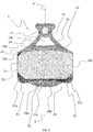
figure 5 is a schematic rear view of the pad offigure 1 and of a pneumatic piston associated therewith; -
figure 6 is a schematic perspective view of a preferred embodiment of a disc brake in accordance with the present invention, associated with a bicycle frame; -
figure 7 is a schematic view from below of what is illustrated infigure 6 ; -
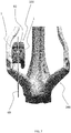
figure 8 is a schematic view from below of the disc brake offigure 6 ; -
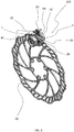
figure 9 is a schematic perspective view of a portion of a first embodiment of a disc brake in accordance with the present invention; -
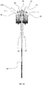
figure 10 is a schematic front view of a portion of an alternative embodiment of the disc brake of the present invention. - In the attached figures,
reference numeral 1 indicates a pad for a bicycle disc brake in accordance with the present invention. - As shown in
figures 6 and7 , the disc brake, indicated with 100, comprises acaliper 50 configured to be associated with theframe 200 of a bicycle and abrake disc 60 configured to be associated with a hub (not shown) of a front or rear wheel of the bicycle. -
Figures 6 and7 show thecaliper 50 associated with the portion of frame of the bicycle at which the rear wheel of the bicycle is mounted. - What is described hereinafter with reference to the pad and to the disc brake of the present invention is valid in an identical manner in the case of a disc brake for a front wheel of the bicycle.
- Inside the
caliper 50 there are at least twoopposite pads 1 in accordance with the present invention. - As shown in
figures 6-10 , thebrake disc 60 comprises a radially outer annular portion that is arranged inside the space defined between thepads 1. By actuating the brake lever (not shown), thepads 1 are brought closer to the brake disc 60 (which rotates integrally with the wheel of the bicycle), generating a friction on thebrake disc 60 and, consequently, braking the wheel. - With reference to
figures 1-5 , thepad 1 comprises aframe 10 intended to be associated with thecaliper 50 and anelement 20 made of friction-wearing material associated with theframe 10. - The
frame 10 is made of a metallic material. - The
frame 10 comprises afastening portion 11 for fastening theframe 10 to thecaliper 50 and asupport portion 15 for supporting theelement 20 made of friction-wearing material. - The
fastening portion 11 comprises ahole 12 for housing apin 13 intended to connect theframe 10 to thecaliper 50. Such apin 13 is shown infigures 8-10 . - As shown in
figure 3 , theframe 10 has a symmetrical shape with respect to a transverse middle plane X-X that passes through the center of thehole 12. - The
fastening portion 11 further comprises a pair ofarms 14 that extend from the area of theframe 10 wherein thehole 12 is formed to the side end areas of the upper part of thesupport portion 15 of theelement 20 made of friction-wearing material, and therefore up to close to the opposite side ends thereof. - A lightening
opening 14a is formed between thearms 14. - As shown in
figure 2 , thesupport portion 15 for supporting theelement 20 made of friction-wearing material comprises a plurality of holes 16 (six in the specific example shown herein) that house by interference corresponding portions of theelement 20 made of friction-wearing material. The latter is therefore coupled with theframe 10 by interference in theholes 16 and, preferably, by gluing on a face of thelower portion 15 of theframe 10. Infigure 2 ,reference numeral 16 is associated with only some of the aforementioned holes. - The
support portion 15 of theelement 20 made of friction-wearing material has a substantially rectangular shape, with alower part 15a that has a central area that projects downwards. - The
element 20 made of friction-wearing material is made of organic materials, like for example glass fibers or copper fibers with resins, or of metallic materials, like for example sintered metallic powders. - The
element 20 made of friction-wearing material has a substantially rectangular shape. It comprises anupper surface 20a, alower surface 20b substantially parallel to theupper surface 20a, and a pair of opposite side surfaces 20c substantially perpendicular to the upper andlower surfaces - The upper and
lower surfaces - The
element 20 made of friction-wearing material has a predetermined thickness and comprises, in a side end area of the upper portion thereof, a visual wearingindicator 25. In particular, the visual wearingindicator 25 is defined at a corner in which theupper surface 20a joins with one of the side surfaces 20c of theelement 20 made of friction-wearing material. - Alternative embodiments to the one shown in the attached drawings are foreseen wherein the visual wearing indicator is provided on both the side end areas of the upper portion of the
element 20 made of friction-wearing material. - The visual wearing
indicator 25 is obtained by partial removal of material, for example through milling. It defines in theelement 20 made of friction-wearing material a step having a height lower than the thickness of theelement 20 made of friction-wearing material. Such a step comprises abase surface 25a, which defines in theelement 20 made of friction-wearing material an area of reduced thickness, and asurface 25b substantially perpendicular to thebase surface 25a and having a height equal to the difference between said predetermined thickness and said reduced thickness. Thesurface 25b is inclined with respect to the upper andside surfaces upper surface 20a and aside surface 20c. - The visual wearing
indicator 25 is defined by thesurface 25b. As the thickness of theelement 20 made of friction-wearing material progressively reduces due to the friction with thebrake disc 60, the height of thesurface 25b reduces, providing the cyclist with a visual indication of the degree of wearing of theelement 20 made of friction-wearing material. -
Figure 8 shows how the visual wearingindicator 25 is visible to the cyclist when thepad 1 is mounted in thecaliper 50. - The
element 20 made of friction-wearing material comprises a beveled lower portion. - Such a beveled lower portion extends continuously along the entire
lower surface 20b of theelement 20 made of friction-wearing material and comprises acentral area 30 having afirst tapering 30a and oppositeside end areas 31 each having a second tapering 31 a. - Alternative embodiments of the
pad 1 of the present invention are foreseen wherein the tapering 31 a is defined only at one of the oppositeside end areas 31. - The tapering 31 a is defined at the opposite corners in which the
lower surface 20b joins with the side surfaces 20c of theelement 20 made of friction-wearing material and extends from thelower surface 20b towards theupper surface 20a of theelement 20 made of friction-wearing material more than thetapering 30a. - Moving progressively from the
central area 30 to the oppositeside end areas 31, thetapering 30a extends increasingly downwards until it joins to the tapering 31 a. The latter extends increasingly towards theupper surface 20a moving progressively towards the side surfaces 20c of theelement 20 made of friction-wearing material. -
Figure 5 shows apneumatic piston 40 associated with thepad 1, in particular with the face of theportion 15 of theframe 10 opposite the one with which theelement 20 made of friction-wearing material is associated. Thepneumatic piston 40 belongs to a pneumatic circuit of a hydraulically-controlleddisc brake 100. - A magnetic element (not visible) is arranged between the
pneumatic piston 40 and theframe 10. Such a magnetic element is fixedly associated with thepneumatic piston 40 and coupled by magnetic attraction with theframe 10. -
Figure 9 shows an embodiment of a hydraulically-controlleddisc brake 100 in accordance with what is described above. In such an embodiment, when the brake lever is actuated eachpneumatic piston 40 pushes therespective pad 1 against thebrake disc 60. When the brake lever is released, eachpneumatic piston 40 goes back into its initial position and eachpad 1 moves away from thebrake disc 60 due to the magnetic attraction exerted by the magnetic element fixedly connected to the respectivepneumatic piston 40. -
Figure 10 shows an alternative embodiment of a hydraulically-controlleddisc brake 100 in accordance with what is described above. In such an embodiment, in place of the aforementioned magnetic element aspring 45 is used. Thespring 45 is arranged between the twoframes 10 of thepads 1 of thedisc brake 100. When the brake lever is activated, eachpneumatic piston 40 pushes therespective pad 1 against thebrake disc 60, stressing thespring 45 by compression. When the brake lever is released, eachpneumatic piston 40 goes back into its initial position and eachpad 1 moves away from thebrake disc 60 through the effect of the elastic thrust exerted by thespring 45. - The
pad 1 described above can also be used in a manually-controlled disc brake. - Of course, those skilled in the art can make numerous modifications and changes to the present invention in order to satisfy specific and contingent requirements, all of which are in any case within the scope of protection defined by the following claims.
Claims (15)
- Pad (1) for a bicycle disc brake (100), comprising a support frame (10) and an element (20) made of friction-wearing material associated with said support frame (10), characterized in that the element (20) made of friction-wearing material comprises a visual wearing indicator (25).
- Pad (1) according to claim 1, wherein the visual wearing indicator (25) is defined on an upper portion of the element (20) made of friction-wearing material.
- Pad (1) according to claim 2, wherein the visual wearing indicator (25) is defined at at least one side end area of said upper portion.
- Pad (1) according to claim 3, wherein the element (20) made of friction-wearing material comprises an upper surface (20a), a lower surface (20b) and two opposite side surfaces (20c), wherein the visual wearing indicator (25) is defined at a corner in which said upper surface (20a) joins with one of said side surfaces (20c).
- Pad (1) according to any one of the previous claims, wherein the element (20) made of friction-wearing material has a predetermined thickness and the visual wearing indicator (25) defines, in the element (20) made of friction-wearing material, a step having a height lower than said predetermined thickness.
- Pad (1) according to claim 5, wherein said step comprises two substantially perpendicular surfaces (25a, 25b), a first surface (25a) of said two surfaces (25a, 25b) defining, in said element (20) made of friction-wearing material, an area of reduced thickness with respect to said predetermined thickness and a second surface (25b) of said two surfaces (25a, 25b) having a height equal to the difference between said predetermined thickness and said reduced thickness, wherein the visual wearing indicator (25) is defined by said second surface (25b).
- Pad (1) according to claim 6 when depending on claim 4, wherein said second surface (25b) is an inclined surface that connects said upper surface (20a) and one of said side surfaces (20c).
- Pad (1) according to any one of claims 5 to 7, wherein said step is obtained by removal of material.
- Pad (1) according to any one of the previous claims, wherein the element (20) made of friction-wearing material comprises a beveled lower portion.
- Pad (1) according to claim 9 when depending on claim 4, wherein said beveled lower portion extends along the entirety of said lower surface (20b).
- Pad (1) according to claim 9 or 10, wherein said beveled lower portion comprises a central area (30) having a first tapering (30a) and opposite side end areas (31) each having a second tapering (31 a), wherein said second tapering (31 a) extends towards said upper surface (20a) more than said first tapering (30a).
- Pad (1) according to claim 11, wherein said second tapering (31 a) is defined at a corner in which said lower surface (20b) joins with at least one of said side surfaces (20c).
- Pad (1) according to any one of the previous claims, wherein the support frame (10) comprises a fastening portion (11) provided with a hole (12) for the attachment of the pad (1) to a caliper (50) of the disc brake (100) and a support portion (15) for supporting the element (20) made of friction-wearing material, wherein said fastening portion (11) comprises a pair of arms (14) that extend from said hole (12) towards opposite side ends of the element (20) made of friction-wearing material.
- Bicycle disc brake (100), comprising a pair of pads (1) according to any one of the previous claims.
- Bicycle disc brake (100) according to claim 14, wherein the support frame (10) is made of a metallic material and wherein the bicycle disc brake (100) comprises a pneumatic piston (40) coupled with the support frame (10) through at least one magnetic element fixedly associated with the pneumatic piston (40) and arranged between the pneumatic piston (40) and the support frame (10).
Applications Claiming Priority (1)
| Application Number | Priority Date | Filing Date | Title |
|---|---|---|---|
| ITUB2015A006084A ITUB20156084A1 (en) | 2015-12-02 | 2015-12-02 | Pad for bicycle disc brake and disc brake including this pad |
Publications (2)
| Publication Number | Publication Date |
|---|---|
| EP3176459A1 true EP3176459A1 (en) | 2017-06-07 |
| EP3176459B1 EP3176459B1 (en) | 2020-07-15 |
Family
ID=55410139
Family Applications (1)
| Application Number | Title | Priority Date | Filing Date |
|---|---|---|---|
| EP16201773.5A Active EP3176459B1 (en) | 2015-12-02 | 2016-12-01 | Pad for a bicycle disc brake and disc brake comprising such a pad |
Country Status (6)
| Country | Link |
|---|---|
| US (1) | US10378605B2 (en) |
| EP (1) | EP3176459B1 (en) |
| JP (1) | JP2017125605A (en) |
| CN (1) | CN106979263A (en) |
| IT (1) | ITUB20156084A1 (en) |
| TW (1) | TWI698370B (en) |
Families Citing this family (6)
| Publication number | Priority date | Publication date | Assignee | Title |
|---|---|---|---|---|
| JP6419966B2 (en) * | 2015-06-30 | 2018-11-07 | 日立オートモティブシステムズ株式会社 | Disc brake |
| IT201700013292A1 (en) * | 2017-02-07 | 2018-08-07 | Campagnolo Srl | Pad for bicycle disc brake |
| JP7164308B2 (en) * | 2018-02-27 | 2022-11-01 | 株式会社シマノ | Friction members and brake pads |
| DE102018207180A1 (en) * | 2018-05-08 | 2019-11-14 | Shimano Components (Malaysia) Sdn. Bhd. | Disc brake caliper with a wear indicator and biasing member for disc brake caliper with a wear indicator |
| IT201800007793A1 (en) * | 2018-08-03 | 2020-02-03 | Campagnolo Srl | Brake pad and caliper for bicycle disc brake |
| CN121025078B (en) * | 2025-10-28 | 2026-01-09 | 山东高原油气装备有限公司 | Disc type brake mechanism of oil pumping unit |
Citations (5)
| Publication number | Priority date | Publication date | Assignee | Title |
|---|---|---|---|---|
| DE20305422U1 (en) * | 2003-04-04 | 2003-11-13 | Wen, Chun-Te, Taichung | Brake pad construction for hydraulic wheel brake of bicycle has each brake pad assembled from grouping of three different linings, with metal lining on inner side, heat insulating lining in middle and sintered metal lining on outside |
| US20050269175A1 (en) * | 2004-06-08 | 2005-12-08 | Shimano, Inc. | Bicycle disk brake pad with friction and wear indicating parts |
| US20070107994A1 (en) * | 2005-11-17 | 2007-05-17 | Mc Clellan W T | Brake pad with wear indicator |
| US20130174656A1 (en) * | 2012-01-06 | 2013-07-11 | Winston MacKelvie | Tell-tale brake pad |
| CN204253681U (en) * | 2014-11-28 | 2015-04-08 | 浙江铭泰汽车零部件有限公司 | A kind of efficient automobile brake block |
Family Cites Families (26)
| Publication number | Priority date | Publication date | Assignee | Title |
|---|---|---|---|---|
| FR1322322A (en) * | 1962-02-16 | 1963-03-29 | Ferodo Sa | Pad for disc brake, its manufacturing method and device |
| US3662863A (en) * | 1968-11-21 | 1972-05-16 | Bendix Corp | Brake lining wear indicator |
| USD277093S (en) * | 1982-03-30 | 1985-01-08 | Girlock Limited | Disc brake pad unit |
| JPH0723630Y2 (en) * | 1990-03-06 | 1995-05-31 | トキコ株式会社 | Disc brake |
| JP2544937Y2 (en) * | 1991-05-22 | 1997-08-20 | 曙ブレーキ工業株式会社 | Disc brake wear indicator |
| DE9203773U1 (en) * | 1991-06-18 | 1992-05-14 | Bergische Achsenfabrik Fr. Kotz & Söhne, 5276 Wiehl | Brake drum |
| US5743361A (en) * | 1995-06-06 | 1998-04-28 | Itt Automotive, Inc. | Light weight brake shoe apparatus with removable friction pad |
| US5791443A (en) * | 1996-04-24 | 1998-08-11 | Dana Corporation | Brake shoe assembly |
| US6105735A (en) * | 1999-01-28 | 2000-08-22 | Lin; Ah-Ping | Brake device for a bicycle |
| DE10218907A1 (en) * | 2002-04-26 | 2003-12-04 | Tmd Friction Europe Gmbh | Chassis assembly for motor vehicles |
| JP4140476B2 (en) * | 2003-07-28 | 2008-08-27 | 株式会社アドヴィックス | Disc brake pad |
| RU2246645C1 (en) * | 2003-11-18 | 2005-02-20 | Открытое акционерное общество "ТЕРМОСТОЙКИЕ ИЗДЕЛИЯ И ИНЖЕНЕРНЫЕ РАЗРАБОТКИ (ОАО "ТИИР") | Friction article |
| DE102004004163B4 (en) * | 2004-01-28 | 2012-12-06 | Bpw Bergische Achsen Kg | Drum brake with brake drum wear indicator |
| US20090084638A1 (en) * | 2004-12-30 | 2009-04-02 | Masterson Steven J | Disc brake pad with visual wear indicator |
| US20070137950A1 (en) * | 2005-12-16 | 2007-06-21 | Heng Tong Machinery Co., Ltd. | Brake shoe return mechanism |
| USD596093S1 (en) * | 2007-08-01 | 2009-07-14 | Federal-Mogul World Wide, Inc. | Brake friction pad |
| USD588973S1 (en) * | 2007-08-01 | 2009-03-24 | Federal Mogul World Wide, Inc. | Brake friction pad |
| USD589419S1 (en) * | 2007-08-01 | 2009-03-31 | Federal-Mogul World Wide, Inc. | Brake friction pad |
| USD588969S1 (en) * | 2007-08-01 | 2009-03-24 | Federal-Mogul World Wide, Inc. | Brake friction pad |
| US8505698B2 (en) * | 2007-08-01 | 2013-08-13 | Federal-Mogul Products, Inc. | Brake pad |
| US20090071766A1 (en) * | 2007-09-13 | 2009-03-19 | Akebono Corporation (North America) | Brake pad assembly with wide slots for the reduction of noise |
| CN201434031Y (en) * | 2009-06-29 | 2010-03-31 | 浦江万赛摩擦材料有限公司 | Disc brake pad |
| US9458904B2 (en) * | 2010-01-04 | 2016-10-04 | Ford Global Technologies, Llc | Disk brake pad |
| DE102011010912A1 (en) * | 2011-02-10 | 2012-08-16 | Lucas Automotive Gmbh | Brake pad assembly for a disc brake and method of making a brake pad assembly |
| KR102087244B1 (en) * | 2014-06-13 | 2020-03-10 | 페더럴-모걸 모터파츠 엘엘씨 | Disc brake pad for a vehicle |
| IT201700013292A1 (en) * | 2017-02-07 | 2018-08-07 | Campagnolo Srl | Pad for bicycle disc brake |
-
2015
- 2015-12-02 IT ITUB2015A006084A patent/ITUB20156084A1/en unknown
-
2016
- 2016-11-30 JP JP2016233548A patent/JP2017125605A/en active Pending
- 2016-12-01 US US15/366,708 patent/US10378605B2/en active Active
- 2016-12-01 TW TW105139594A patent/TWI698370B/en active
- 2016-12-01 EP EP16201773.5A patent/EP3176459B1/en active Active
- 2016-12-02 CN CN201611101243.XA patent/CN106979263A/en active Pending
Patent Citations (5)
| Publication number | Priority date | Publication date | Assignee | Title |
|---|---|---|---|---|
| DE20305422U1 (en) * | 2003-04-04 | 2003-11-13 | Wen, Chun-Te, Taichung | Brake pad construction for hydraulic wheel brake of bicycle has each brake pad assembled from grouping of three different linings, with metal lining on inner side, heat insulating lining in middle and sintered metal lining on outside |
| US20050269175A1 (en) * | 2004-06-08 | 2005-12-08 | Shimano, Inc. | Bicycle disk brake pad with friction and wear indicating parts |
| US20070107994A1 (en) * | 2005-11-17 | 2007-05-17 | Mc Clellan W T | Brake pad with wear indicator |
| US20130174656A1 (en) * | 2012-01-06 | 2013-07-11 | Winston MacKelvie | Tell-tale brake pad |
| CN204253681U (en) * | 2014-11-28 | 2015-04-08 | 浙江铭泰汽车零部件有限公司 | A kind of efficient automobile brake block |
Also Published As
| Publication number | Publication date |
|---|---|
| JP2017125605A (en) | 2017-07-20 |
| CN106979263A (en) | 2017-07-25 |
| EP3176459B1 (en) | 2020-07-15 |
| TW201720705A (en) | 2017-06-16 |
| US10378605B2 (en) | 2019-08-13 |
| US20170159736A1 (en) | 2017-06-08 |
| ITUB20156084A1 (en) | 2017-06-02 |
| TWI698370B (en) | 2020-07-11 |
Similar Documents
| Publication | Publication Date | Title |
|---|---|---|
| EP3176459B1 (en) | Pad for a bicycle disc brake and disc brake comprising such a pad | |
| KR102553993B1 (en) | Drum brake | |
| US20090152056A1 (en) | Disk Brake With Guard Screen | |
| CN105909698B (en) | Disc brake caliper, brake(-holder) block component and biasing member component | |
| EP3121477B1 (en) | A disc brake assembly | |
| MX2008001884A (en) | Brake support plate. | |
| WO2010009885A8 (en) | Disc brake, especially for a commercial vehicle | |
| EP1122161A3 (en) | Bicycle disk brake | |
| US20180223927A1 (en) | Pad for a bicycle disc brake | |
| JP2017125605A5 (en) | ||
| US11091220B2 (en) | Pad and brake caliper for a bicycle disc brake | |
| EP3415411A2 (en) | Pad for a bicycle disc brake and bicycle disc brake assembly comprising such a pad | |
| US3402790A (en) | Spot type disc brakes | |
| US3552526A (en) | Brakeshoe construction for disk brakes | |
| EP1399681B1 (en) | Brake lining wear system | |
| JP5587876B2 (en) | Caliper body support structure for vehicle disc brakes | |
| US3470985A (en) | Disc brakes | |
| US7370733B2 (en) | Disc brake friction couple wear indicator | |
| EP2045482B1 (en) | Disc brake device, spring and vehicle and using such a disc brake device or spring | |
| HUE025174T2 (en) | Disc brake, in particular for a commercial vehicle | |
| CN106030145B (en) | For the disk brake of commerial vehicle | |
| WO2003064880A1 (en) | Torque plate | |
| JP4926121B2 (en) | Disc brake | |
| AU2001246612A1 (en) | Brake calliper comprising at least two opposite pistons | |
| CN110446877A (en) | Disc brakes for commercial vehicles |
Legal Events
| Date | Code | Title | Description |
|---|---|---|---|
| AK | Designated contracting states |
Kind code of ref document: A1 Designated state(s): AL AT BE BG CH CY CZ DE DK EE ES FI FR GB GR HR HU IE IS IT LI LT LU LV MC MK MT NL NO PL PT RO RS SE SI SK SM TR |
|
| AX | Request for extension of the european patent |
Extension state: BA ME |
|
| PUAI | Public reference made under article 153(3) epc to a published international application that has entered the european phase |
Free format text: ORIGINAL CODE: 0009012 |
|
| STAA | Information on the status of an ep patent application or granted ep patent |
Free format text: STATUS: THE APPLICATION HAS BEEN PUBLISHED |
|
| STAA | Information on the status of an ep patent application or granted ep patent |
Free format text: STATUS: REQUEST FOR EXAMINATION WAS MADE |
|
| 17P | Request for examination filed |
Effective date: 20171206 |
|
| RBV | Designated contracting states (corrected) |
Designated state(s): AL AT BE BG CH CY CZ DE DK EE ES FI FR GB GR HR HU IE IS IT LI LT LU LV MC MK MT NL NO PL PT RO RS SE SI SK SM TR |
|
| STAA | Information on the status of an ep patent application or granted ep patent |
Free format text: STATUS: EXAMINATION IS IN PROGRESS |
|
| 17Q | First examination report despatched |
Effective date: 20190603 |
|
| GRAJ | Information related to disapproval of communication of intention to grant by the applicant or resumption of examination proceedings by the epo deleted |
Free format text: ORIGINAL CODE: EPIDOSDIGR1 |
|
| STAA | Information on the status of an ep patent application or granted ep patent |
Free format text: STATUS: GRANT OF PATENT IS INTENDED |
|
| GRAP | Despatch of communication of intention to grant a patent |
Free format text: ORIGINAL CODE: EPIDOSNIGR1 |
|
| INTG | Intention to grant announced |
Effective date: 20200206 |
|
| RIN1 | Information on inventor provided before grant (corrected) |
Inventor name: MEGGIOLAN, MARIO |
|
| GRAS | Grant fee paid |
Free format text: ORIGINAL CODE: EPIDOSNIGR3 |
|
| GRAA | (expected) grant |
Free format text: ORIGINAL CODE: 0009210 |
|
| STAA | Information on the status of an ep patent application or granted ep patent |
Free format text: STATUS: THE PATENT HAS BEEN GRANTED |
|
| AK | Designated contracting states |
Kind code of ref document: B1 Designated state(s): AL AT BE BG CH CY CZ DE DK EE ES FI FR GB GR HR HU IE IS IT LI LT LU LV MC MK MT NL NO PL PT RO RS SE SI SK SM TR |
|
| REG | Reference to a national code |
Ref country code: GB Ref legal event code: FG4D Ref country code: CH Ref legal event code: EP |
|
| REG | Reference to a national code |
Ref country code: IE Ref legal event code: FG4D |
|
| REG | Reference to a national code |
Ref country code: DE Ref legal event code: R096 Ref document number: 602016039896 Country of ref document: DE |
|
| REG | Reference to a national code |
Ref country code: AT Ref legal event code: REF Ref document number: 1291370 Country of ref document: AT Kind code of ref document: T Effective date: 20200815 |
|
| REG | Reference to a national code |
Ref country code: LT Ref legal event code: MG4D |
|
| REG | Reference to a national code |
Ref country code: AT Ref legal event code: MK05 Ref document number: 1291370 Country of ref document: AT Kind code of ref document: T Effective date: 20200715 |
|
| REG | Reference to a national code |
Ref country code: NL Ref legal event code: MP Effective date: 20200715 |
|
| PG25 | Lapsed in a contracting state [announced via postgrant information from national office to epo] |
Ref country code: ES Free format text: LAPSE BECAUSE OF FAILURE TO SUBMIT A TRANSLATION OF THE DESCRIPTION OR TO PAY THE FEE WITHIN THE PRESCRIBED TIME-LIMIT Effective date: 20200715 Ref country code: PT Free format text: LAPSE BECAUSE OF FAILURE TO SUBMIT A TRANSLATION OF THE DESCRIPTION OR TO PAY THE FEE WITHIN THE PRESCRIBED TIME-LIMIT Effective date: 20201116 Ref country code: BG Free format text: LAPSE BECAUSE OF FAILURE TO SUBMIT A TRANSLATION OF THE DESCRIPTION OR TO PAY THE FEE WITHIN THE PRESCRIBED TIME-LIMIT Effective date: 20201015 Ref country code: SE Free format text: LAPSE BECAUSE OF FAILURE TO SUBMIT A TRANSLATION OF THE DESCRIPTION OR TO PAY THE FEE WITHIN THE PRESCRIBED TIME-LIMIT Effective date: 20200715 Ref country code: LT Free format text: LAPSE BECAUSE OF FAILURE TO SUBMIT A TRANSLATION OF THE DESCRIPTION OR TO PAY THE FEE WITHIN THE PRESCRIBED TIME-LIMIT Effective date: 20200715 Ref country code: HR Free format text: LAPSE BECAUSE OF FAILURE TO SUBMIT A TRANSLATION OF THE DESCRIPTION OR TO PAY THE FEE WITHIN THE PRESCRIBED TIME-LIMIT Effective date: 20200715 Ref country code: AT Free format text: LAPSE BECAUSE OF FAILURE TO SUBMIT A TRANSLATION OF THE DESCRIPTION OR TO PAY THE FEE WITHIN THE PRESCRIBED TIME-LIMIT Effective date: 20200715 Ref country code: GR Free format text: LAPSE BECAUSE OF FAILURE TO SUBMIT A TRANSLATION OF THE DESCRIPTION OR TO PAY THE FEE WITHIN THE PRESCRIBED TIME-LIMIT Effective date: 20201016 Ref country code: NO Free format text: LAPSE BECAUSE OF FAILURE TO SUBMIT A TRANSLATION OF THE DESCRIPTION OR TO PAY THE FEE WITHIN THE PRESCRIBED TIME-LIMIT Effective date: 20201015 Ref country code: FI Free format text: LAPSE BECAUSE OF FAILURE TO SUBMIT A TRANSLATION OF THE DESCRIPTION OR TO PAY THE FEE WITHIN THE PRESCRIBED TIME-LIMIT Effective date: 20200715 |
|
| PG25 | Lapsed in a contracting state [announced via postgrant information from national office to epo] |
Ref country code: IS Free format text: LAPSE BECAUSE OF FAILURE TO SUBMIT A TRANSLATION OF THE DESCRIPTION OR TO PAY THE FEE WITHIN THE PRESCRIBED TIME-LIMIT Effective date: 20201115 Ref country code: RS Free format text: LAPSE BECAUSE OF FAILURE TO SUBMIT A TRANSLATION OF THE DESCRIPTION OR TO PAY THE FEE WITHIN THE PRESCRIBED TIME-LIMIT Effective date: 20200715 Ref country code: PL Free format text: LAPSE BECAUSE OF FAILURE TO SUBMIT A TRANSLATION OF THE DESCRIPTION OR TO PAY THE FEE WITHIN THE PRESCRIBED TIME-LIMIT Effective date: 20200715 Ref country code: LV Free format text: LAPSE BECAUSE OF FAILURE TO SUBMIT A TRANSLATION OF THE DESCRIPTION OR TO PAY THE FEE WITHIN THE PRESCRIBED TIME-LIMIT Effective date: 20200715 |
|
| PG25 | Lapsed in a contracting state [announced via postgrant information from national office to epo] |
Ref country code: NL Free format text: LAPSE BECAUSE OF FAILURE TO SUBMIT A TRANSLATION OF THE DESCRIPTION OR TO PAY THE FEE WITHIN THE PRESCRIBED TIME-LIMIT Effective date: 20200715 |
|
| REG | Reference to a national code |
Ref country code: DE Ref legal event code: R097 Ref document number: 602016039896 Country of ref document: DE |
|
| PG25 | Lapsed in a contracting state [announced via postgrant information from national office to epo] |
Ref country code: EE Free format text: LAPSE BECAUSE OF FAILURE TO SUBMIT A TRANSLATION OF THE DESCRIPTION OR TO PAY THE FEE WITHIN THE PRESCRIBED TIME-LIMIT Effective date: 20200715 Ref country code: CZ Free format text: LAPSE BECAUSE OF FAILURE TO SUBMIT A TRANSLATION OF THE DESCRIPTION OR TO PAY THE FEE WITHIN THE PRESCRIBED TIME-LIMIT Effective date: 20200715 Ref country code: DK Free format text: LAPSE BECAUSE OF FAILURE TO SUBMIT A TRANSLATION OF THE DESCRIPTION OR TO PAY THE FEE WITHIN THE PRESCRIBED TIME-LIMIT Effective date: 20200715 Ref country code: SM Free format text: LAPSE BECAUSE OF FAILURE TO SUBMIT A TRANSLATION OF THE DESCRIPTION OR TO PAY THE FEE WITHIN THE PRESCRIBED TIME-LIMIT Effective date: 20200715 Ref country code: RO Free format text: LAPSE BECAUSE OF FAILURE TO SUBMIT A TRANSLATION OF THE DESCRIPTION OR TO PAY THE FEE WITHIN THE PRESCRIBED TIME-LIMIT Effective date: 20200715 |
|
| PLBE | No opposition filed within time limit |
Free format text: ORIGINAL CODE: 0009261 |
|
| STAA | Information on the status of an ep patent application or granted ep patent |
Free format text: STATUS: NO OPPOSITION FILED WITHIN TIME LIMIT |
|
| PG25 | Lapsed in a contracting state [announced via postgrant information from national office to epo] |
Ref country code: AL Free format text: LAPSE BECAUSE OF FAILURE TO SUBMIT A TRANSLATION OF THE DESCRIPTION OR TO PAY THE FEE WITHIN THE PRESCRIBED TIME-LIMIT Effective date: 20200715 |
|
| 26N | No opposition filed |
Effective date: 20210416 |
|
| PG25 | Lapsed in a contracting state [announced via postgrant information from national office to epo] |
Ref country code: SK Free format text: LAPSE BECAUSE OF FAILURE TO SUBMIT A TRANSLATION OF THE DESCRIPTION OR TO PAY THE FEE WITHIN THE PRESCRIBED TIME-LIMIT Effective date: 20200715 |
|
| REG | Reference to a national code |
Ref country code: CH Ref legal event code: PL |
|
| GBPC | Gb: european patent ceased through non-payment of renewal fee |
Effective date: 20201201 |
|
| PG25 | Lapsed in a contracting state [announced via postgrant information from national office to epo] |
Ref country code: SI Free format text: LAPSE BECAUSE OF FAILURE TO SUBMIT A TRANSLATION OF THE DESCRIPTION OR TO PAY THE FEE WITHIN THE PRESCRIBED TIME-LIMIT Effective date: 20200715 Ref country code: MC Free format text: LAPSE BECAUSE OF FAILURE TO SUBMIT A TRANSLATION OF THE DESCRIPTION OR TO PAY THE FEE WITHIN THE PRESCRIBED TIME-LIMIT Effective date: 20200715 |
|
| REG | Reference to a national code |
Ref country code: BE Ref legal event code: MM Effective date: 20201231 |
|
| PG25 | Lapsed in a contracting state [announced via postgrant information from national office to epo] |
Ref country code: LU Free format text: LAPSE BECAUSE OF NON-PAYMENT OF DUE FEES Effective date: 20201201 Ref country code: FR Free format text: LAPSE BECAUSE OF NON-PAYMENT OF DUE FEES Effective date: 20201231 Ref country code: IE Free format text: LAPSE BECAUSE OF NON-PAYMENT OF DUE FEES Effective date: 20201201 |
|
| PG25 | Lapsed in a contracting state [announced via postgrant information from national office to epo] |
Ref country code: CH Free format text: LAPSE BECAUSE OF NON-PAYMENT OF DUE FEES Effective date: 20201231 Ref country code: LI Free format text: LAPSE BECAUSE OF NON-PAYMENT OF DUE FEES Effective date: 20201231 Ref country code: GB Free format text: LAPSE BECAUSE OF NON-PAYMENT OF DUE FEES Effective date: 20201201 |
|
| PG25 | Lapsed in a contracting state [announced via postgrant information from national office to epo] |
Ref country code: IS Free format text: LAPSE BECAUSE OF FAILURE TO SUBMIT A TRANSLATION OF THE DESCRIPTION OR TO PAY THE FEE WITHIN THE PRESCRIBED TIME-LIMIT Effective date: 20201115 Ref country code: TR Free format text: LAPSE BECAUSE OF FAILURE TO SUBMIT A TRANSLATION OF THE DESCRIPTION OR TO PAY THE FEE WITHIN THE PRESCRIBED TIME-LIMIT Effective date: 20200715 Ref country code: MT Free format text: LAPSE BECAUSE OF FAILURE TO SUBMIT A TRANSLATION OF THE DESCRIPTION OR TO PAY THE FEE WITHIN THE PRESCRIBED TIME-LIMIT Effective date: 20200715 Ref country code: CY Free format text: LAPSE BECAUSE OF FAILURE TO SUBMIT A TRANSLATION OF THE DESCRIPTION OR TO PAY THE FEE WITHIN THE PRESCRIBED TIME-LIMIT Effective date: 20200715 |
|
| PG25 | Lapsed in a contracting state [announced via postgrant information from national office to epo] |
Ref country code: MK Free format text: LAPSE BECAUSE OF FAILURE TO SUBMIT A TRANSLATION OF THE DESCRIPTION OR TO PAY THE FEE WITHIN THE PRESCRIBED TIME-LIMIT Effective date: 20200715 |
|
| PG25 | Lapsed in a contracting state [announced via postgrant information from national office to epo] |
Ref country code: BE Free format text: LAPSE BECAUSE OF NON-PAYMENT OF DUE FEES Effective date: 20201231 |
|
| P01 | Opt-out of the competence of the unified patent court (upc) registered |
Effective date: 20230516 |
|
| PGFP | Annual fee paid to national office [announced via postgrant information from national office to epo] |
Ref country code: IT Payment date: 20251219 Year of fee payment: 10 |
|
| PGFP | Annual fee paid to national office [announced via postgrant information from national office to epo] |
Ref country code: DE Payment date: 20251229 Year of fee payment: 10 |