EP3176413A1 - Shovel - Google Patents
Shovel Download PDFInfo
- Publication number
- EP3176413A1 EP3176413A1 EP15826439.0A EP15826439A EP3176413A1 EP 3176413 A1 EP3176413 A1 EP 3176413A1 EP 15826439 A EP15826439 A EP 15826439A EP 3176413 A1 EP3176413 A1 EP 3176413A1
- Authority
- EP
- European Patent Office
- Prior art keywords
- engine speed
- controller
- hydraulic
- engine
- shovel
- Prior art date
- Legal status (The legal status is an assumption and is not a legal conclusion. Google has not performed a legal analysis and makes no representation as to the accuracy of the status listed.)
- Granted
Links
Images



Classifications
-
- E—FIXED CONSTRUCTIONS
- E02—HYDRAULIC ENGINEERING; FOUNDATIONS; SOIL SHIFTING
- E02F—DREDGING; SOIL-SHIFTING
- E02F3/00—Dredgers; Soil-shifting machines
- E02F3/04—Dredgers; Soil-shifting machines mechanically-driven
- E02F3/28—Dredgers; Soil-shifting machines mechanically-driven with digging tools mounted on a dipper- or bucket-arm, i.e. there is either one arm or a pair of arms, e.g. dippers, buckets
- E02F3/36—Component parts
- E02F3/42—Drives for dippers, buckets, dipper-arms or bucket-arms
- E02F3/43—Control of dipper or bucket position; Control of sequence of drive operations
- E02F3/435—Control of dipper or bucket position; Control of sequence of drive operations for dipper-arms, backhoes or the like
-
- E—FIXED CONSTRUCTIONS
- E02—HYDRAULIC ENGINEERING; FOUNDATIONS; SOIL SHIFTING
- E02F—DREDGING; SOIL-SHIFTING
- E02F3/00—Dredgers; Soil-shifting machines
- E02F3/04—Dredgers; Soil-shifting machines mechanically-driven
- E02F3/28—Dredgers; Soil-shifting machines mechanically-driven with digging tools mounted on a dipper- or bucket-arm, i.e. there is either one arm or a pair of arms, e.g. dippers, buckets
- E02F3/30—Dredgers; Soil-shifting machines mechanically-driven with digging tools mounted on a dipper- or bucket-arm, i.e. there is either one arm or a pair of arms, e.g. dippers, buckets with a dipper-arm pivoted on a cantilever beam, i.e. boom
- E02F3/32—Dredgers; Soil-shifting machines mechanically-driven with digging tools mounted on a dipper- or bucket-arm, i.e. there is either one arm or a pair of arms, e.g. dippers, buckets with a dipper-arm pivoted on a cantilever beam, i.e. boom working downwardly and towards the machine, e.g. with backhoes
-
- E—FIXED CONSTRUCTIONS
- E02—HYDRAULIC ENGINEERING; FOUNDATIONS; SOIL SHIFTING
- E02F—DREDGING; SOIL-SHIFTING
- E02F9/00—Component parts of dredgers or soil-shifting machines, not restricted to one of the kinds covered by groups E02F3/00 - E02F7/00
- E02F9/20—Drives; Control devices
-
- E—FIXED CONSTRUCTIONS
- E02—HYDRAULIC ENGINEERING; FOUNDATIONS; SOIL SHIFTING
- E02F—DREDGING; SOIL-SHIFTING
- E02F9/00—Component parts of dredgers or soil-shifting machines, not restricted to one of the kinds covered by groups E02F3/00 - E02F7/00
- E02F9/20—Drives; Control devices
- E02F9/22—Hydraulic or pneumatic drives
- E02F9/2221—Control of flow rate; Load sensing arrangements
- E02F9/2232—Control of flow rate; Load sensing arrangements using one or more variable displacement pumps
- E02F9/2235—Control of flow rate; Load sensing arrangements using one or more variable displacement pumps including an electronic controller
-
- E—FIXED CONSTRUCTIONS
- E02—HYDRAULIC ENGINEERING; FOUNDATIONS; SOIL SHIFTING
- E02F—DREDGING; SOIL-SHIFTING
- E02F9/00—Component parts of dredgers or soil-shifting machines, not restricted to one of the kinds covered by groups E02F3/00 - E02F7/00
- E02F9/20—Drives; Control devices
- E02F9/22—Hydraulic or pneumatic drives
- E02F9/2246—Control of prime movers, e.g. depending on the hydraulic load of work tools
-
- E—FIXED CONSTRUCTIONS
- E02—HYDRAULIC ENGINEERING; FOUNDATIONS; SOIL SHIFTING
- E02F—DREDGING; SOIL-SHIFTING
- E02F9/00—Component parts of dredgers or soil-shifting machines, not restricted to one of the kinds covered by groups E02F3/00 - E02F7/00
- E02F9/20—Drives; Control devices
- E02F9/22—Hydraulic or pneumatic drives
- E02F9/2278—Hydraulic circuits
- E02F9/2282—Systems using center bypass type changeover valves
-
- E—FIXED CONSTRUCTIONS
- E02—HYDRAULIC ENGINEERING; FOUNDATIONS; SOIL SHIFTING
- E02F—DREDGING; SOIL-SHIFTING
- E02F9/00—Component parts of dredgers or soil-shifting machines, not restricted to one of the kinds covered by groups E02F3/00 - E02F7/00
- E02F9/20—Drives; Control devices
- E02F9/22—Hydraulic or pneumatic drives
- E02F9/2278—Hydraulic circuits
- E02F9/2292—Systems with two or more pumps
-
- E—FIXED CONSTRUCTIONS
- E02—HYDRAULIC ENGINEERING; FOUNDATIONS; SOIL SHIFTING
- E02F—DREDGING; SOIL-SHIFTING
- E02F9/00—Component parts of dredgers or soil-shifting machines, not restricted to one of the kinds covered by groups E02F3/00 - E02F7/00
- E02F9/20—Drives; Control devices
- E02F9/22—Hydraulic or pneumatic drives
- E02F9/2278—Hydraulic circuits
- E02F9/2296—Systems with a variable displacement pump
-
- F—MECHANICAL ENGINEERING; LIGHTING; HEATING; WEAPONS; BLASTING
- F02—COMBUSTION ENGINES; HOT-GAS OR COMBUSTION-PRODUCT ENGINE PLANTS
- F02D—CONTROLLING COMBUSTION ENGINES
- F02D29/00—Controlling engines, such controlling being peculiar to the devices driven thereby, the devices being other than parts or accessories essential to engine operation, e.g. controlling of engines by signals external thereto
-
- F—MECHANICAL ENGINEERING; LIGHTING; HEATING; WEAPONS; BLASTING
- F02—COMBUSTION ENGINES; HOT-GAS OR COMBUSTION-PRODUCT ENGINE PLANTS
- F02D—CONTROLLING COMBUSTION ENGINES
- F02D29/00—Controlling engines, such controlling being peculiar to the devices driven thereby, the devices being other than parts or accessories essential to engine operation, e.g. controlling of engines by signals external thereto
- F02D29/04—Controlling engines, such controlling being peculiar to the devices driven thereby, the devices being other than parts or accessories essential to engine operation, e.g. controlling of engines by signals external thereto peculiar to engines driving pumps
-
- F—MECHANICAL ENGINEERING; LIGHTING; HEATING; WEAPONS; BLASTING
- F02—COMBUSTION ENGINES; HOT-GAS OR COMBUSTION-PRODUCT ENGINE PLANTS
- F02D—CONTROLLING COMBUSTION ENGINES
- F02D31/00—Use of speed-sensing governors to control combustion engines, not otherwise provided for
- F02D31/001—Electric control of rotation speed
- F02D31/007—Electric control of rotation speed controlling fuel supply
-
- F—MECHANICAL ENGINEERING; LIGHTING; HEATING; WEAPONS; BLASTING
- F02—COMBUSTION ENGINES; HOT-GAS OR COMBUSTION-PRODUCT ENGINE PLANTS
- F02D—CONTROLLING COMBUSTION ENGINES
- F02D45/00—Electrical control not provided for in groups F02D41/00 - F02D43/00
Definitions
- the present invention relates to a shovel including an engine and a hydraulic pump driven by the engine.
- the overload protection device When it is determined that an operation lever of the construction machine is operated at a speed greater than or equal to a predetermined speed, the overload protection device temporarily decreases the maximum allowable value of torque that the hydraulic pump can absorb This is to prevent the discharge rate of the hydraulic pump from increasing sharply in response to the sharp increase in the discharge pressure of the hydraulic pump, and thereby prevent the pump absorption torque from exceeding the engine output torque. This in turn makes it possible to reduce the fuel consumption of the construction machine and to improve the maneuverability of, for example, a hydraulic actuator.
- the device increases the fuel injection amount to cause the engine speed to return to the rated speed.
- Patent Document 1 Japanese Patent No. 4806014
- the above-described device is not configured to actively control the output torque of an engine to which isochronous control is applied, to prevent the occurrence of an engine lug-down resulting from a sharp increase in the discharge pressure of a hydraulic pump. Accordingly, the device has room for improvement in terms of suppressing the variation in engine speed.
- a shovel including a lower traveling body, an upper rotating body, an attachment including a boom and an arm, a controller, an engine, and a hydraulic pump that is driven by the engine and discharges hydraulic oil to drive the attachment.
- the controller is configured to obtain a hydraulic load applied to the attachment and calculate an engine speed command at predetermined time intervals based on the obtained hydraulic load.
- An embodiment of the present invention makes it possible to provide a shovel that can more reliably suppress the variation in the engine speed resulting from a change in pump absorption torque.
- FIG. 1 is a drawing illustrating an exemplary configuration of a shovel (excavator) that is an example of a construction machine according to an embodiment of the present invention.
- a shovel 1 includes a crawler-type lower traveling body 2, and an upper rotating body 3 that is mounted via a rotating mechanism on the lower traveling body and is rotatable about an X axis.
- An excavating attachment which is an example of an attachment, is provided on a front center portion of the upper rotating body 3.
- the excavating attachment includes a boom 4, an arm 5, and a bucket 6. Any other attachment such as a lifting magnet attachment may instead be provided on the upper rotating body 3.
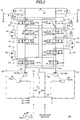
- FIG. 2 is a drawing illustrating a drive system 100 of the shovel 1.
- the drive system 100 includes hydraulic pumps 10, an engine 11, a control valve system 17, a controller 30, and an engine controller 35.
- each hydraulic pump 10 is a variable-displacement, swash-plate hydraulic pump whose discharge rate per revolution (actual displacement [cc/rev]) is variable.
- the actual displacement [cc/rev] is controlled by a pump regulator 10a.
- the hydraulic pumps 10 include a hydraulic pump 10L whose discharge rate is controlled by a pump regulator 10aL and a hydraulic pump 10R whose discharge rate is controlled by a pump regulator 10aR.
- the rotational shaft of the hydraulic pump 10 is coupled to the rotational shaft of the engine 11 and rotates at the same rotation speed as the rotation speed of the engine 11.
- the rotational shaft of the hydraulic pump 10 is coupled to a flywheel. The flywheel suppresses variation in the rotation speed resulting from variation in engine output torque.
- the engine 11 is a driving source of the shovel 1.
- the engine 11 is a diesel engine including a turbocharger as a booster and a fuel injector, and is provided in the upper rotating body 3.
- the engine 11 may include a supercharger as a booster.
- the control valve system 17 is a hydraulic control mechanism that supplies hydraulic oil discharged from the hydraulic pumps 10 to various hydraulic actuators.
- the control valve system 17 includes control valves 171L, 171R, 172L, 172R, 173L, 173R, 174R, 175L, and 175R.
- the hydraulic actuators include a boom cylinder 7, an arm cylinder 8, a bucket cylinder 9, a left traveling hydraulic motor 42L, a right traveling hydraulic motor 42R, and a rotating hydraulic motor 44.
- the hydraulic pump 10L circulates hydraulic oil through a center bypass pipe line 20L, which passes through the control valves 171L, 172L, 173L, and 175L, to a hydraulic oil tank 22.
- the hydraulic pump 10R circulates hydraulic oil through a center bypass pipe line 20R, which passes through the control valves 171R, 172R, 173R, 174R, and 175R, to the hydraulic oil tank 22.
- the control valve 171L is a spool valve that controls the flow rate and the flow direction of the hydraulic oil between the left traveling hydraulic motor 42L and the hydraulic pump 10L.
- the control valve 171R is a spool valve that functions as a straight travel valve.
- the control valve 171R switches the flow of the hydraulic oil so that the hydraulic oil is supplied from the hydraulic pump 10L to each of the left traveling hydraulic motor 42L and the right traveling hydraulic motor 42R, and the straight line stability of the lower travelling body 2 is improved. More specifically, when the left traveling hydraulic motor 42L, the right traveling hydraulic motor 42R, and another hydraulic actuator are operated at the same time, the hydraulic pump 10 supplies the hydraulic oil to both of the left traveling hydraulic motor 42L and the right traveling hydraulic motor 42R. In other cases, the hydraulic pump 10L supplies the hydraulic oil to the left traveling hydraulic motor 42L and the hydraulic pump 10R supplies the hydraulic oil to the right traveling hydraulic motor 42R.
- the control valve 172L is a spool valve that controls the flow rate and the flow direction of the hydraulic oil between the rotating hydraulic motor 44 and the hydraulic pump 10L.
- the control valve 172R is a spool valve that controls the flow rate and the flow direction of the hydraulic oil between the right traveling hydraulic motor 42R and the hydraulic pumps 10L and 10R.
- the control valves 173L and 173R are spool valves that control the flow rates and the flow directions of the hydraulic oil between the boom cylinder 7 and the corresponding hydraulic pumps 10L and 10R.
- the control valve 173R is driven when a boom operation lever, which is an operation device, is operated.
- the control valve 173L is driven when the boom operation lever is operated in a boom raising direction by an amount greater than or equal to a predetermined lever operation amount.
- the control valve 174R is a spool valve that controls the flow rate and the flow direction of the hydraulic oil between the hydraulic pump 10R and the bucket cylinder 9.
- the control valves 175L and 175R are spool valves that control the flow rates and the flow directions of the hydraulic oil between the arm cylinder 8 and the corresponding hydraulic pumps 10L and 10R.
- the control valve 175L is driven when an arm operation lever, which is an operation device, is operated.
- the control valve 175R is driven when the arm operation lever is operated by an amount greater than or equal to a predetermined lever operation amount.
- the center bypass pipe lines 20L and 20R include negative control throttles 21L and 21R between the most downstream flow control valves 175L and 175R and the hydraulic oil tank 22.
- the negative control throttles 21L and 21R respectively, limit the flows of the hydraulic oil discharged from the hydraulic pumps 10L and 10R to generate negative control pressures at positions upstream of the negative control throttles 21L and 21R.
- the controller 30 is a functional component for controlling the shovel 1 and is, for example, a computer including a CPU, a RAM, a ROM, and an NVRAM.
- the controller 30 electrically detects operations (e.g., whether a lever is operated, a lever operation direction, and a lever operation amount) of various operation devices based on outputs of a pilot pressure sensor(s) (not shown).
- the pilot pressure sensor is an example of an operation detector for measuring a pilot pressure that is generated when an operation device such as an arm operation lever or a boom operation lever is operated.
- the operation detector may be implemented by a sensor other than a pilot pressure sensor.
- the operation detector may be implemented by an inclination sensor that detects an inclination of an operation lever.
- the controller 30 also electrically detects operation states of the engine 11 and various hydraulic actuators based on outputs from sensors S1 through S7.
- Pressure sensors S1 and S2 detect negative control pressures generated upstream of the negative control throttles 21L and 21R, and output the detected negative control pressures as electric negative control pressure signals to the controller 30.
- Pressure sensors S3 and S4 detect discharge pressures of the hydraulic pumps 10L and 10R, and output the detected discharge pressures as electric discharge pressure signals to the controller 30.
- An engine speed sensor S5 detects the speed of the engine 11, and outputs the detected speed as an electric engine speed signal to the controller 30 and the engine controller 35.
- a boost pressure sensor S6 detects a boost pressure of the engine 11, and outputs the detected boost pressure as an electric boost pressure signal to the controller 30 and the engine controller 35.
- the boost pressure sensor S6 detects the intake pressure (boost pressure) increased by a turbocharger.
- the controller 30 may instead be configured to obtain the output of the boost pressure sensor S6 via the engine controller 35.
- Actuator pressure sensors S7 detect pressures of the hydraulic oil in the respective hydraulic actuators, and output the detected pressures as electric actuator pressure signals to the controller 30.
- the controller 30 causes the CPU to execute programs corresponding to various functional components.
- the engine controller 35 is a device that controls the engine 11.
- the engine controller 35 controls (isochronous control) the engine 11 at a constant speed according to an engine speed command that is received at predetermined time intervals from the controller 30 via CAN communications. More specifically, at a predetermined control cycle, the engine controller 35 calculates a speed deviation between an engine speed command received from the controller 30 at the predetermined control cycle and an actual engine speed detected by the engine speed sensor S5 at the predetermined control cycle. Then, at the predetermined control cycle, the engine controller 35 increases or decreases the engine output torque by increasing or decreasing the fuel injection amount according to the calculated speed deviation. That is, the engine controller 35 performs a feedback control of the engine speed at the predetermined control cycle.
- the controller 30 can increase or decrease the fuel injection amount and eventually the engine output torque in advance by increasing or decreasing the engine speed command at the predetermined control cycle in a feedforward manner. Accordingly, the controller 30 can suppress the variation in the engine speed by increasing or decreasing the engine output torque according to an engine load before the engine speed varies. Thus, the controller 30 can prevent a lug-down of the engine 11 due to a response delay resulting from the feedback control described above. Also, the controller 30 can prevent a decrease in responsiveness of hydraulic actuators at start-up that is caused by a decrease in the pumping rate resulting from a decrease in the engine speed. Also, because the controller 30 does not uniformly decrease the pumping rate to prevent the lug-down of the engine 11, the movement of the hydraulic actuators is not slowed down more than necessary, and the operability of the shovel 1 is not excessively degraded.
- the engine controller 35 also calculates a fuel injection limiting value based on the boost pressure, and controls the fuel injector according to the fuel injection limiting value.
- the fuel injection limiting value may include a maximum allowable fuel injection amount that is determined according to the boost pressure, and fuel injection timing.
- An engine speed adjusting dial 75 which is an engine speed setter, is used to adjust a target engine speed.
- the engine speed adjusting dial 75 is provided in a cabin of the shovel 1 and allows an operator of the shovel 1 to set the target engine speed at one of four levels. Also, the engine speed adjusting dial 75 sends data indicating the set target engine speed to the controller 30.
- the operator can set the engine speed by selecting one of four modes including a work priority mode, a normal mode, an energy-saving priority mode, and an idling mode.
- the work priority mode is a speed mode that is selected to give priority to the workload, and uses the highest engine speed among the four modes.
- the normal mode is a speed mode that is selected to satisfy both the workload and the fuel efficiency, and uses the second highest engine speed among the four modes.
- the energy-saving priority mode is a speed mode that is selected to operate the shovel 1 with low noise while giving priority to the fuel efficiency, and uses the third highest engine speed among the four modes.
- the idling mode is a speed mode that is selected to cause the engine to idle, and uses the lowest engine speed among the four modes.
- the engine 11 is maintained at an engine speed corresponding to a mode selected by the engine speed adjusting dial 75.
- the controller 30 increases or decreases the discharge rate of the hydraulic pump 10L by increasing or decreasing a control current supplied to the pump regulator 10aL and thereby increasing or decreasing the swash plate angle of the hydraulic pump 10L.
- the controller 30 increases the discharge rate of the hydraulic pump 10L by increasing the control current as the negative pressure decreases.
- the hydraulic oil discharged by the hydraulic pump 10L passes through the center bypass pipe line 20L, reaches the negative control throttle 21L, and generates a negative control pressure at a position upstream of the negative control throttle 21L.
- the controller 30 increases the control current supplied to the pump regulator 10aL.
- the pump regulator 10aL increases the swash plate angle of the hydraulic pump 10L and thereby increases the discharge rate. As a result, a sufficient amount of the hydraulic oil is supplied to the arm cylinder 8, and the arm cylinder 8 is properly driven.
- the controller 30 decreases the control current supplied to the pump regulator 10aL. According to the decrease in the control current from the controller 30, the pump regulator 10aL decreases the swash plate angle of the hydraulic pump 10L and thereby decreases the discharge rate. As a result, a pressure loss (pumping loss) caused when the hydraulic oil discharged by the hydraulic pump 10L passes through the center bypass pipe line 20L is suppressed.
- a process of controlling the pumping rate based on a negative control pressure as described above is referred to as a "negative control".
- the drive system 100 can reduce wasteful energy consumption in a standby state where the hydraulic actuators are not being operated. This is because the negative control can suppress the pumping loss caused by the hydraulic oil discharged by the hydraulic pumps 10. Also, the drive system 100 can supply a sufficient amount of the hydraulic oil from the hydraulic pumps 10 to the hydraulic actuators to drive the hydraulic actuators.
- the drive system 100 also performs a horsepower control in parallel with the negative control.
- the horsepower control decreases the pumping rate as the discharge pressure (which is hereafter referred to as a "pump discharge pressure) of the hydraulic pump 10 increases. This is to prevent the occurrence of over torque.
- the horsepower control is performed to prevent the absorbing horsepower (pump absorption torque) of the hydraulic pump, which is represented by a product of the pump discharge pressure and the pumping rate, from exceeding the output horsepower (engine output torque) of the engine.
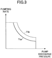
- FIG. 3 is a horsepower control diagram (PQ diagram) illustrating a relationship between the pumping rate and the pump discharge pressure.
- the vertical axis indicates the pumping rate and the horizontal axis indicates the pump discharge pressure.
- a horsepower control line indicates a tendency that the pumping rate increases as the pumping discharge pressure decreases.
- a horsepower control line is determined according to target pump absorption torque. As the target pump absorption torque increases, the horsepower control line shifts in an upper-right direction.
- FIG. 3 indicates that target pump absorption torque Tta corresponding to a horsepower control line represented by a solid line is smaller than target pump absorption torque Ttb corresponding to a horsepower control line represented by a dotted line.
- the target pump absorption torque is set in advance as maximum allowable pump absorption torque that the hydraulic pump 10 can output. Although the target pump absorption torque is set in advance as a fixed value in the present embodiment, the target pump absorption torque may instead be a variable.
- the controller 30 controls the displacement of the hydraulic pump 10 according to a horsepower control line as illustrated in FIG. 3 . Specifically, the controller 30 calculates a target displacement based on a pumping rate corresponding to a pump discharge pressure detected by the pressure sensor S3. Then, the controller 30 outputs a control current corresponding to the target displacement to the pump regulator 10a. The pump regulator 10a increases or decreases the swash plate angle according to the control current so that the displacement of the hydraulic pump 10 matches the target displacement. With the feedback control of the pump absorption torque as described above, the controller 30 can drive the hydraulic pump 10 at the target pump absorption torque even when the pump discharge pressure varies due to the variation of the load of a hydraulic actuator. Also, the engine controller 35 adjusts engine output torque by a feedback control by referring to, for example, the actual engine speed and the boost pressure, to maintain a target engine speed specified by the controller 30 (isochronous control).
- the controller 30 cannot eliminate a response delay time necessary to actually change the pumping rate after a variation in the pump discharge pressure is detected. This may cause the pump absorption torque to exceed the engine output torque.
- the engine controller 35 cannot eliminate a response delay time necessary to actually change the engine output torque after a variation in the actual engine speed is detected. This may cause the actual engine speed to vary greatly (or deviate greatly from the target engine speed).
- the controller 30 employs a model predictive control.
- the controller 30 predicts, at a predetermined control cycle, an engine speed after a predetermined period of time based on the state quantity of the hydraulic pump 10 at the present time, and generates an engine speed command for the engine controller 35 at the predetermined control cycle.
- the state quantity of the hydraulic pump 10 at the present time may include, for example, a pump discharge pressure, a displacement, a swash plate angle, and pump absorption torque (hydraulic load).
- the controller 30 may be configured to predict, for example, the load of the engine 11 and a decrease in the engine speed, and generate an engine speed command based on the predicted values.
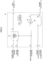
- FIG. 4 is a block diagram illustrating an exemplary flow of control performed by the controller 30.
- the arm 5 is independently operated.
- the controller 30 reads target pump absorption torque (Tt) that is preset in, for example, the NVRAM. Also, the controller 30 obtains a boost pressure (Pb) of the booster of the engine 11 that is detected by the boost pressure sensor S6. Then, the controller 30 adjusts the target pump absorption torque (Tt) at an arithmetical element E1.
- Tt target pump absorption torque
- Pb boost pressure
- the arithmetical element E1 adjusts the target pump absorption torque (Tt) according to the boost pressure (Pb). For example, when the boost pressure (Pb) is greater than or equal to a predetermined value, the arithmetical element E1 adjusts the target pump absorption torque Tta to the target pump absorption torque Ttb as illustrated in FIG. 3 , and uses the dotted horsepower control line corresponding to the target pump absorption torque Ttb instead of the solid horsepower control line corresponding to the target pump absorption torque Tta.
- the arithmetical element E1 may be configured to additionally or alternatively adjust the target pump absorption torque (Tt) according to a fuel injection limiting value output from the engine controller 35.
- the arithmetical element E1 may be configured to adjust the target pump absorption torque by referring to a correspondence table (correspondence map) that stores the correspondence between boost pressures (Pb) or fuel injection limiting values and target pump absorption torque (Tt), or configured to adjust the target pump absorption torque by using a predetermined formula.
- a correspondence table correlates the correspondence between boost pressures (Pb) or fuel injection limiting values and target pump absorption torque (Tt)
- the controller 30 can prevent the target pump absorption torque from being set at an excessively high value when the boost pressure of the engine 11 is low at the start of the operation of a hydraulic actuator.
- the controller 30 can prevent the occurrence of over torque, and can also prevent a delay in the recovery of the engine speed after its decrease due to a notable influence of a turbo lag.
- the controller 30 calculates a target displacement (Dt) of the hydraulic pump 10 as a swash-plate angle command.
- the arithmetic element E1 calculates a pumping rate corresponding to the pump discharge pressure in the horsepower control.
- the arithmetic element E1 refers to the horsepower control line as illustrated in FIG. 3 , and calculates a target displacement (Dt) corresponding to a pump discharge pressure (Pd) of the hydraulic pump 10L detected by the pressure sensor S3.
- the pump regulator 10aL receives a control current corresponding to the target displacement (Dt) and changes the actual displacement [cc/rev] of the hydraulic pump 10L according to the control current.
- FIG. 4 also illustrates a process where the target displacement (Dt) is converted into an estimated value (Dd') of the actual displacement [cc/rev] via an arithmetic element E2 that is a pump model of the hydraulic pump 10L.
- the controller 30 electrically controls the pumping rate of the hydraulic pump 10L based on the target displacement (Dt). For this reason, it is possible to estimate the actual displacement [cc/rev] by using a pump model (a virtual swash-plate angle sensor) of the hydraulic pump 10L.
- This configuration enables the controller 30 to estimate pump absorption torque (Tp) without using a swash-plate angle sensor, and makes it possible to improve the responsiveness in the engine speed control while suppressing a cost increase.
- the pump model of the hydraulic pump 10L is generated based on input-output data during actual operations of the hydraulic pump 10L.
- the hydraulic pump 10L discharges the hydraulic oil at a pumping rate that is determined by the actual displacement [cc/rev] controlled by the pump regulator 10aL and the pump speed of the hydraulic pump 10L corresponding to the actual engine speed ( ⁇ ) of the engine 11.
- a model prediction controller 30a of the controller 30 adjusts the target engine speed ( ⁇ t) based on the target engine speed ( ⁇ t), the actual engine speed ( ⁇ ), and the pump absorption torque (Tp). Then, the model prediction controller 30a outputs an adjusted target engine speed ( ⁇ t1) as an engine speed command to the engine controller 35.
- the model prediction controller 30a is a functional component that performs, in real time, a control (model prediction control) based on an optimal control theory by using a model for predicting the behavior of the engine 11 and the engine controller 35.
- the model prediction control of the engine 11 is performed by using a plant model of the engine 11.
- the plant model of the engine 11 enables obtaining an output of the engine 11 based on an input to the engine 11.
- the model prediction controller 30a obtains a predicted value of the engine speed after "n" control cycles in a case where a small variation ( ⁇ t) is continuously applied to the target engine speed ( ⁇ t) (i.e., where the target engine speed varies by ⁇ t at every control cycle) while the engine load torque (pump absorption torque (Tp)) is present.
- the model prediction controller 30a obtains a predicted value of the engine speed after the "n" control cycles in a case where multiple small variation values obtained based on the small variation ⁇ t are continuously applied to the target engine speed ( ⁇ t) throughout the "n" control cycles.
- Each of the small variation values may be obtained, for example, by adding a predetermined value to the small variation ⁇ t or by subtracting a predetermined value from the small variation ⁇ t.
- the model prediction controller 30a selects, from the multiple small variation values, a small variation ⁇ tc that minimizes the difference between the current target engine speed ( ⁇ t) and the engine speed (predicted value) after the "n" control cycles. Specifically, the model prediction controller 30a selects one of the small variation values including the small variation ⁇ t as the small variation ⁇ tc to be used for the current control cycle.
- the model prediction controller 30a adds the selected small variation ⁇ tc to the target engine speed ( ⁇ t) to obtain an adjusted target engine speed ( ⁇ t1), and outputs the adjusted target engine speed ( ⁇ t1) as an engine speed command to the engine controller 35.
- the engine controller 35 obtains a fuel injection amount (Qi) based on the adjusted target engine speed ( ⁇ t1) output from the model prediction controller 30a.
- the engine load torque input to the model prediction controller 30a is the same as the pump absorption torque (Tp).
- the engine load torque may instead be a value that is obtained by adding no-load loss torque and/or a viscous resistance to the pump absorption torque (Tp).
- the model prediction controller 30a can obtain an adjusted target engine speed ( ⁇ t1) that provides engine output torque (fuel injection amount) that is necessary to maintain the target engine speed ( ⁇ t) and corresponds to the pump absorption torque (Tp), and output the adjusted target engine speed ( ⁇ t1) to the engine controller 35.
- the model prediction controller 30a obtains the target engine speed ( ⁇ t) from the engine speed adjusting dial 75, obtains the actual engine speed ( ⁇ ) from the engine speed sensor S5, and obtains the pump absorption toque (Tp) from an arithmetic element E3.
- the arithmetic element E3 is a functional component that calculates the pump absorption toque (Tp) based on the estimated value (Dd') of the actual displacement [cc/rev] of the hydraulic pump 10L and the pump discharge pressure (Pd) of the hydraulic pump 10L that is detected by the pressure sensor S3.
- the model prediction controller 30a can calculate the pump absorption torque (Tp) based on past variations of the pump absorption torque (Tp). This configuration makes it possible to more accurately obtain a predicted value of the engine speed.
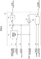
- FIG. 5 is a block diagram illustrating an exemplary flow of control performed by the engine controller 35.
- the engine controller 35 obtains a deviation ( ⁇ ) between the adjusted target engine speed ( ⁇ t1) and the actual engine speed ( ⁇ ).
- the engine controller 35 calculates the fuel injection amount (Qi) via an arithmetic element E10.
- the arithmetic element E10 is comprised of an anti-windup controller and a PID controller, and prevents the saturation of the deviation ( ⁇ ) that is a control input.
- the engine controller 35 obtains an adjusted fuel injection amount corresponding to the current boost pressure (Pb) by referring to a correspondence table (correspondence map) that stores the correspondence between boost pressures and fuel injection amounts.
- the engine controller 35 calculates a difference between the fuel injection amount (Qi) and the adjusted fuel injection amount, and feeds back the difference to the arithmetic element E10. This is to prevent integral windup. Then, the fuel injector of the engine 11 injects an amount of fuel corresponding to the adjusted fuel injection amount.
- the above configuration of the drive system 100 makes it possible to suppress the variation in the engine speed by inputting, to the engine controller 35, the adjusted target engine speed ( ⁇ t1) that provides engine output torque (fuel injection amount) corresponding to the pump absorption torque (Tp).
- the above configuration of the drive system 100 can provide characteristics that are close to the characteristics of a torque control (where the engine output torque is directly adjusted according to the pump absorption torque).
- the configuration of the drive system 100 makes it possible to maintain the engine speed at a substantially constant level while suppressing a response delay resulting from the feedback control.
- the configuration of the drive system 100 does not require the operator of the shovel 1 to manually control the engine speed taking into account the characteristic of the engine 11.
- the drive system 100 includes the model prediction controller 30a that performs a model prediction control of the engine 11.
- the model prediction controller 30a makes it possible to indirectly adjust the engine controller 35. This in turn eliminates the need to modify the engine controller 35 itself even when the control procedure is changed, and thereby makes it possible to reduce the development costs.
- FIG. 6 is a graph illustrating changes over time in the engine speed command, the actual engine speed, and the pump absorption torque (hydraulic load).
- a solid line indicates changes in the actual engine speed in a case where the model prediction control is employed
- a dashed line indicates changes in the actual engine speed in a case where the model prediction control is not employed. Also in FIG.
- a one-dot chain line indicates changes in the engine speed command in the case where the model prediction control is employed, and a two-dot chain line indicates changes in the engine speed command in the case where the model prediction control is not employed.
- a solid line indicates changes in the pump absorption torque that is common to the case where the model prediction control is employed and the case where the model prediction control is not employed.
- the model prediction controller 30a of the controller 30 increases the engine speed command to be output to the engine controller 35 as indicated by the one-dot chain line in FIG. 6 (A) .
- the engine speed command is determined at predetermined time intervals based on the target engine speed set by the engine speed setter. Specifically, the engine speed command is determined so that the difference between the current target engine speed and the actual engine speed (predicted value) after "n" control cycles is minimized. Also, the engine speed command tends to increase as the pump absorption torque increases.
- the controller 30 of the present invention can generate an adjusted target engine speed that is lower than the target engine speed, and therefore can prevent the overspeeding of the engine 11.
- the engine speed command continues to increase until the pump absorption torque reaches the maximum value (a value Tp1 that is determined by the horsepower control line) at a time t2, and reaches the maximal value at substantially the same time as the pump absorption torque reaches the maximum value.
- the engine speed command reaches the maximal value at a time earlier than a time t3 at which the actual engine speed reaches the minimal value. After that, the engine speed command gradually decreases and returns to the initial engine speed command (which is observed before the time t1). As a result, as indicated by the solid line in FIG. 6 (A) , the actual engine speed only slightly and temporarily decreases up to the minimal value observed at the time t3 and is maintained at a substantially constant level. When the engine speed command is ideally predicted, the actual engine speed may not even slightly and temporarily decrease and is maintained at a constant level.
- the controller 30 does not change the engine speed command as indicated by the two-dot chain line in FIG. 6 (A) . Accordingly, as indicated by the dashed line in FIG. 6 (A) , the actual engine speed decreases comparatively greatly and then returns to a value corresponding to the engine speed command.
- the controller 30 can prevent the actual engine speed from decreasing drastically even when the pump absorption torque increases sharply.
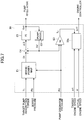
- FIG. 7 is a block diagram illustrating another exemplary flow of control performed by the controller 30 and is a variation of FIG. 4 .
- the arm 5 is independently operated.
- the flow of control of FIG. 7 is different from the flow of control of FIG. 4 in that a deviation ( ⁇ D) between a target displacement (Dt) and an estimated value (Dd') of the current actual displacement [cc/rev] is calculated by an arithmetic element E4, and an adjusted target displacement (Dt1) is obtained by an arithmetic element E5 by adjusting the target displacement (Dt) such that the deviation ( ⁇ D) becomes close to zero.
- Other parts of FIG. 7 are substantially the same as those of FIG. 4 . Below, descriptions of the same parts are omitted, and different parts are described in detail.
- the arithmetic element E4 is a subtracter that outputs the deviation ( ⁇ D) by subtracting the estimated value (Dd') of the current actual displacement [cc/rev] from the target displacement (Dt).
- the estimated value (Dd') of the current actual displacement [cc/rev] is based on the adjusted target displacement (Dt1) obtained by the arithmetic element E5, and is calculated by using the pump model of the arithmetic element E2 as a current swash-plate angle.
- the arithmetical element E5 is a PI controller that adjusts the target displacement (Dt) according to the deviation ( ⁇ D).
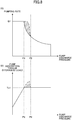
- FIG. 8 is a graph illustrating a relationship between a pumping rate and a pump discharge pressure, and a relationship between pump absorption torque and a pump discharge pressure.
- the vertical axis of FIG. 8 (A) indicates the pumping rate
- the vertical axis of FIG. 8 (B) indicates the pump absorption torque.
- the horizontal axes of FIG. 8 (A) and FIG. 8 (B) indicate the pump discharge pressure and correspond to each other.
- FIG. 8 (A) is a horsepower control diagram and corresponds to FIG. 3 .
- the hydraulic pump 10L supplies the hydraulic oil to the arm cylinder 8 at a pumping rate Q1 as indicated in FIG. 8 (A) .
- the controller 30 decreases the pumping rate to follow a horsepower control line in FIG. 8 (A) .
- the pump absorption torque reaches a value Tp1 that is determined by the horsepower control line as indicated by a solid line in FIG. 8 (B) .
- the controller 30 increases or decreases the pumping rate to follow the horsepower control line in FIG. 8 (A) .
- the pump absorption torque is maintained at the value Tp1 that is determined by the horsepower control line as indicated by the solid line in FIG. 8 (B) .
- the controller 30 may become unable to decrease the pumping rate to follow the horsepower control line in FIG. 8 (A) .
- the pumping rate temporarily exceeds the value determined by the horsepower control line
- the pump absorption torque also temporarily exceeds the value Tp1 determined by the horsepower control line.
- a hatched area in FIG. 8 (A) indicates the pumping rate exceeding the value determined by the horsepower control line
- a hatched area in FIG. 8 (B) indicates the pump absorption torque exceeding the value Tp1 determined by the horsepower control line.
- the arithmetic element E5 implemented by a PI controller can reduce or prevent the occurrence of the above situation. Specifically, the arithmetic element E5 makes it possible to comparatively quickly decrease the pumping rate even when the pump discharge pressure sharply increases beyond the value PI, and makes it possible to suppress or prevent the pumping rate from exceeding the value determined by the horsepower control line. This in turn makes it possible to suppress or prevent the pump absorption torque from exceeding the value Tp1 determined by the horsepower control line.
- FIG. 9 is a block diagram illustrating still another exemplary flow of control performed by the controller 30 and is a variation of FIG. 7 .
- the arm 5 is independently operated.
- the flow of control of FIG. 9 is different from the flow of control of FIG. 7 in that the arithmetic element E2, which is a pump model, is omitted, a swash-plate angle sensor is added, and a value detected by the swash-plate angle sensor is input to each of the arithmetic element E3 and the arithmetic element E4.
- Other parts of FIG. 9 are substantially the same as those of FIG. 7 . Below, descriptions of the same parts are omitted, and different parts are described in detail.
- the arithmetic element E4 outputs a deviation ( ⁇ D) by subtracting a current actual displacement (Dd) detected by the swash-plate angle sensor from the target displacement (Dt). Also in FIG. 9 , the arithmetic element E3 calculates the pump absorption toque (Tp) based on the actual displacement (Dd) of the hydraulic pump 10L detected by the swash-plate angle sensor and the pump discharge pressure (Pd) of the hydraulic pump 10L detected by the pressure sensor S3. Specifically, the arithmetic element E3 calculates the pump absorption toque (Tp) by multiplying the current actual displacement (Dd) by a predetermined proportional gain (Kp) corresponding to the pump discharge pressure (Pd).
- Kp proportional gain
- the flow of control of FIG. 9 provides effects similar to those provided by the flow of control of FIG. 7 , and also makes it possible to more accurately and stably control the actual engine speed ( ⁇ ).
- the controller 30 may be configured to calculate the pump absorption toque (Tp) based on the pressure of the hydraulic oil in the hydraulic actuator detected by the pressure sensor S7. For example, when the arm 5 is independently operated in a closing direction, the controller 30 may calculate the pump absorption toque (Tp) based on the pressure of the hydraulic oil in a bottom-side oil chamber of the arm cylinder 8.
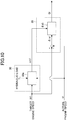
- FIG. 10 is a block diagram illustrating another exemplary flow of control performed by the engine controller 35 and is a variation of FIG. 5 .
- the flow of control of FIG. 10 is different from the flow of control of FIG. 5 in that the engine controller 35 calculates a deviation ( ⁇ ) between a target engine speed ( ⁇ t) and an actual engine speed ( ⁇ ), and the arithmetic element E10 calculates a fuel injection amount (Qi) based on an adjusted target engine speed ( ⁇ t1) output from the model prediction controller 30a and the deviation ( ⁇ ).
- Other parts of FIG. 10 are substantially the same as those of FIG. 5 . Below, descriptions of the same parts are omitted, and different parts are described in detail.
- the engine controller 35 of FIG. 10 receives the target engine speed ( ⁇ t) instead of the adjusted target engine speed ( ⁇ t1) and calculates the deviation ( ⁇ ) between the target engine speed ( ⁇ t) and the actual engine speed ( ⁇ ).
- the arithmetic element E10 of FIG. 10 receives the adjusted target engine speed ( ⁇ t1) in addition to the deviation ( ⁇ ), and calculates the fuel injection amount (Qi) while preventing the saturation of the deviation ( ⁇ ) as a control input.
- the engine controller 35 of FIG. 10 can calculate the deviation ( ⁇ ) and adjust the fuel injection amount (Qi) taking into account the adjusted target engine speed ( ⁇ t1). Accordingly, compared with the engine controller 35 of FIG. 5 , the engine controller 35 of FIG. 10 can more flexibly adjust the fuel injection amount (Qi) and can provide characteristics that are close to the characteristics of a torque control (where the engine output torque is directly adjusted according to the pump absorption torque).
- the drive system 100 is used in the above embodiment to suppress the variation in the engine speed of the engine 11 of the shovel 1, the drive system 100 may also be used to suppress the variation in the engine speed of an engine used as a driving source of a power generator.
- controller 30 and the engine controller 35 are provided as separate components in the above embodiment, the controller 30 and the engine controller 35 may be combined into a single component.
Landscapes
- Engineering & Computer Science (AREA)
- General Engineering & Computer Science (AREA)
- Mining & Mineral Resources (AREA)
- Structural Engineering (AREA)
- Civil Engineering (AREA)
- Mechanical Engineering (AREA)
- Chemical & Material Sciences (AREA)
- Combustion & Propulsion (AREA)
- Physics & Mathematics (AREA)
- Fluid Mechanics (AREA)
- Operation Control Of Excavators (AREA)
- Control Of Positive-Displacement Pumps (AREA)
- Control Of Vehicle Engines Or Engines For Specific Uses (AREA)
- Combined Controls Of Internal Combustion Engines (AREA)
Abstract
Description
- The present invention relates to a shovel including an engine and a hydraulic pump driven by the engine.
- There exists an overload protection device for a construction machine that prevents the occurrence of an engine lug-down resulting from a sharp increase in the discharge pressure of a hydraulic pump, and thereby prevents a sharp increase in the fuel injection amount (see Patent Document 1).
- When it is determined that an operation lever of the construction machine is operated at a speed greater than or equal to a predetermined speed, the overload protection device temporarily decreases the maximum allowable value of torque that the hydraulic pump can absorb This is to prevent the discharge rate of the hydraulic pump from increasing sharply in response to the sharp increase in the discharge pressure of the hydraulic pump, and thereby prevent the pump absorption torque from exceeding the engine output torque. This in turn makes it possible to reduce the fuel consumption of the construction machine and to improve the maneuverability of, for example, a hydraulic actuator. On the other hand, when engine speed decreases, the device increases the fuel injection amount to cause the engine speed to return to the rated speed.
- [Patent Document 1] Japanese Patent No.
4806014 - However, the above-described device is not configured to actively control the output torque of an engine to which isochronous control is applied, to prevent the occurrence of an engine lug-down resulting from a sharp increase in the discharge pressure of a hydraulic pump. Accordingly, the device has room for improvement in terms of suppressing the variation in engine speed.
- For the reasons discussed above, it is preferable to provide a shovel that can more reliably suppress the variation in engine speed resulting from a change in pump absorption torque.
- According to an embodiment of the present invention, there is provided a shovel including a lower traveling body, an upper rotating body, an attachment including a boom and an arm, a controller, an engine, and a hydraulic pump that is driven by the engine and discharges hydraulic oil to drive the attachment. The controller is configured to obtain a hydraulic load applied to the attachment and calculate an engine speed command at predetermined time intervals based on the obtained hydraulic load.
- An embodiment of the present invention makes it possible to provide a shovel that can more reliably suppress the variation in the engine speed resulting from a change in pump absorption torque.
-
-
FIG. 1 is a drawing illustrating an exemplary configuration of a shovel according to an embodiment of the present invention; -
FIG. 2 is a drawing illustrating an exemplary configuration of a drive system of the shovel ofFIG. 1 ; -
FIG. 3 is a horsepower control diagram (PQ diagram) illustrating a relationship between a pumping rate and a pump discharge pressure; -
FIG. 4 is a block diagram illustrating an exemplary flow of control performed by a controller; -
FIG. 5 is a block diagram illustrating an exemplary flow of control performed by an engine controller; -
FIG. 6 is a graph illustrating changes over time in an engine speed command, an actual engine speed, and pump absorption torque (hydraulic load); -
FIG. 7 is a block diagram illustrating another exemplary flow of control performed by a controller; -
FIG. 8 is a graph illustrating a relationship between a pumping rate and a pump discharge pressure, and a relationship between pump absorption torque and a pump discharge pressure; -
FIG. 9 is a block diagram illustrating still another exemplary flow of control performed by a controller; and -
FIG. 10 is a block diagram illustrating another exemplary flow of control performed by an engine controller. - Preferred embodiments of the present invention are described below with reference to the accompanying drawings.
FIG. 1 is a drawing illustrating an exemplary configuration of a shovel (excavator) that is an example of a construction machine according to an embodiment of the present invention. Ashovel 1 includes a crawler-type lower travelingbody 2, and an upper rotatingbody 3 that is mounted via a rotating mechanism on the lower traveling body and is rotatable about an X axis. An excavating attachment, which is an example of an attachment, is provided on a front center portion of the upper rotatingbody 3. The excavating attachment includes aboom 4, anarm 5, and abucket 6. Any other attachment such as a lifting magnet attachment may instead be provided on the upper rotatingbody 3. -
FIG. 2 is a drawing illustrating adrive system 100 of theshovel 1. Thedrive system 100 includeshydraulic pumps 10, anengine 11, acontrol valve system 17, acontroller 30, and anengine controller 35. - The
hydraulic pumps 10 are driven by theengine 11. In the present embodiment, eachhydraulic pump 10 is a variable-displacement, swash-plate hydraulic pump whose discharge rate per revolution (actual displacement [cc/rev]) is variable. The actual displacement [cc/rev] is controlled by apump regulator 10a. More specifically, thehydraulic pumps 10 include ahydraulic pump 10L whose discharge rate is controlled by a pump regulator 10aL and ahydraulic pump 10R whose discharge rate is controlled by a pump regulator 10aR. Also, in the present embodiment, the rotational shaft of thehydraulic pump 10 is coupled to the rotational shaft of theengine 11 and rotates at the same rotation speed as the rotation speed of theengine 11. Also, the rotational shaft of thehydraulic pump 10 is coupled to a flywheel. The flywheel suppresses variation in the rotation speed resulting from variation in engine output torque. - The
engine 11 is a driving source of theshovel 1. In the present embodiment, theengine 11 is a diesel engine including a turbocharger as a booster and a fuel injector, and is provided in the upper rotatingbody 3. Theengine 11 may include a supercharger as a booster. - The
control valve system 17 is a hydraulic control mechanism that supplies hydraulic oil discharged from thehydraulic pumps 10 to various hydraulic actuators. In the present embodiment, thecontrol valve system 17 includescontrol valves boom cylinder 7, anarm cylinder 8, abucket cylinder 9, a left travelinghydraulic motor 42L, a right travelinghydraulic motor 42R, and a rotatinghydraulic motor 44. - Specifically, the
hydraulic pump 10L circulates hydraulic oil through a centerbypass pipe line 20L, which passes through thecontrol valves hydraulic oil tank 22. Similarly, thehydraulic pump 10R circulates hydraulic oil through a centerbypass pipe line 20R, which passes through thecontrol valves hydraulic oil tank 22. - The
control valve 171L is a spool valve that controls the flow rate and the flow direction of the hydraulic oil between the left travelinghydraulic motor 42L and thehydraulic pump 10L. - The
control valve 171R is a spool valve that functions as a straight travel valve. Thecontrol valve 171R switches the flow of the hydraulic oil so that the hydraulic oil is supplied from thehydraulic pump 10L to each of the left travelinghydraulic motor 42L and the right travelinghydraulic motor 42R, and the straight line stability of thelower travelling body 2 is improved. More specifically, when the left travelinghydraulic motor 42L, the right travelinghydraulic motor 42R, and another hydraulic actuator are operated at the same time, thehydraulic pump 10 supplies the hydraulic oil to both of the left travelinghydraulic motor 42L and the right travelinghydraulic motor 42R. In other cases, thehydraulic pump 10L supplies the hydraulic oil to the left travelinghydraulic motor 42L and thehydraulic pump 10R supplies the hydraulic oil to the right travelinghydraulic motor 42R. - The
control valve 172L is a spool valve that controls the flow rate and the flow direction of the hydraulic oil between the rotatinghydraulic motor 44 and thehydraulic pump 10L. Thecontrol valve 172R is a spool valve that controls the flow rate and the flow direction of the hydraulic oil between the right travelinghydraulic motor 42R and thehydraulic pumps - The
control valves boom cylinder 7 and the correspondinghydraulic pumps control valve 173R is driven when a boom operation lever, which is an operation device, is operated. Thecontrol valve 173L is driven when the boom operation lever is operated in a boom raising direction by an amount greater than or equal to a predetermined lever operation amount. - The
control valve 174R is a spool valve that controls the flow rate and the flow direction of the hydraulic oil between thehydraulic pump 10R and thebucket cylinder 9. - The
control valves arm cylinder 8 and the correspondinghydraulic pumps control valve 175L is driven when an arm operation lever, which is an operation device, is operated. Thecontrol valve 175R is driven when the arm operation lever is operated by an amount greater than or equal to a predetermined lever operation amount. - The center
bypass pipe lines flow control valves hydraulic oil tank 22. The negative control throttles 21L and 21R, respectively, limit the flows of the hydraulic oil discharged from thehydraulic pumps - The
controller 30 is a functional component for controlling theshovel 1 and is, for example, a computer including a CPU, a RAM, a ROM, and an NVRAM. - In the present embodiment, the
controller 30 electrically detects operations (e.g., whether a lever is operated, a lever operation direction, and a lever operation amount) of various operation devices based on outputs of a pilot pressure sensor(s) (not shown). The pilot pressure sensor is an example of an operation detector for measuring a pilot pressure that is generated when an operation device such as an arm operation lever or a boom operation lever is operated. Alternatively, the operation detector may be implemented by a sensor other than a pilot pressure sensor. For example, the operation detector may be implemented by an inclination sensor that detects an inclination of an operation lever. - The
controller 30 also electrically detects operation states of theengine 11 and various hydraulic actuators based on outputs from sensors S1 through S7. - Pressure sensors S1 and S2 detect negative control pressures generated upstream of the negative control throttles 21L and 21R, and output the detected negative control pressures as electric negative control pressure signals to the
controller 30. - Pressure sensors S3 and S4 detect discharge pressures of the
hydraulic pumps controller 30. - An engine speed sensor S5 detects the speed of the
engine 11, and outputs the detected speed as an electric engine speed signal to thecontroller 30 and theengine controller 35. - A boost pressure sensor S6 detects a boost pressure of the
engine 11, and outputs the detected boost pressure as an electric boost pressure signal to thecontroller 30 and theengine controller 35. In the present embodiment, the boost pressure sensor S6 detects the intake pressure (boost pressure) increased by a turbocharger. Thecontroller 30 may instead be configured to obtain the output of the boost pressure sensor S6 via theengine controller 35. - Actuator pressure sensors S7 detect pressures of the hydraulic oil in the respective hydraulic actuators, and output the detected pressures as electric actuator pressure signals to the
controller 30. - According to detected operations of the operation devices and detected operation states of the hydraulic actuators, the
controller 30 causes the CPU to execute programs corresponding to various functional components. - The
engine controller 35 is a device that controls theengine 11. In the present embodiment, theengine controller 35 controls (isochronous control) theengine 11 at a constant speed according to an engine speed command that is received at predetermined time intervals from thecontroller 30 via CAN communications. More specifically, at a predetermined control cycle, theengine controller 35 calculates a speed deviation between an engine speed command received from thecontroller 30 at the predetermined control cycle and an actual engine speed detected by the engine speed sensor S5 at the predetermined control cycle. Then, at the predetermined control cycle, theengine controller 35 increases or decreases the engine output torque by increasing or decreasing the fuel injection amount according to the calculated speed deviation. That is, theengine controller 35 performs a feedback control of the engine speed at the predetermined control cycle. - Also, the
controller 30 can increase or decrease the fuel injection amount and eventually the engine output torque in advance by increasing or decreasing the engine speed command at the predetermined control cycle in a feedforward manner. Accordingly, thecontroller 30 can suppress the variation in the engine speed by increasing or decreasing the engine output torque according to an engine load before the engine speed varies. Thus, thecontroller 30 can prevent a lug-down of theengine 11 due to a response delay resulting from the feedback control described above. Also, thecontroller 30 can prevent a decrease in responsiveness of hydraulic actuators at start-up that is caused by a decrease in the pumping rate resulting from a decrease in the engine speed. Also, because thecontroller 30 does not uniformly decrease the pumping rate to prevent the lug-down of theengine 11, the movement of the hydraulic actuators is not slowed down more than necessary, and the operability of theshovel 1 is not excessively degraded. - The
engine controller 35 also calculates a fuel injection limiting value based on the boost pressure, and controls the fuel injector according to the fuel injection limiting value. The fuel injection limiting value may include a maximum allowable fuel injection amount that is determined according to the boost pressure, and fuel injection timing. - An engine
speed adjusting dial 75, which is an engine speed setter, is used to adjust a target engine speed. In the present embodiment, the enginespeed adjusting dial 75 is provided in a cabin of theshovel 1 and allows an operator of theshovel 1 to set the target engine speed at one of four levels. Also, the enginespeed adjusting dial 75 sends data indicating the set target engine speed to thecontroller 30. - More specifically, the operator can set the engine speed by selecting one of four modes including a work priority mode, a normal mode, an energy-saving priority mode, and an idling mode. In
FIG. 2 , it is assumed that the energy-saving priority mode is selected with the enginespeed adjusting dial 75. The work priority mode is a speed mode that is selected to give priority to the workload, and uses the highest engine speed among the four modes. The normal mode is a speed mode that is selected to satisfy both the workload and the fuel efficiency, and uses the second highest engine speed among the four modes. The energy-saving priority mode is a speed mode that is selected to operate theshovel 1 with low noise while giving priority to the fuel efficiency, and uses the third highest engine speed among the four modes. The idling mode is a speed mode that is selected to cause the engine to idle, and uses the lowest engine speed among the four modes. Theengine 11 is maintained at an engine speed corresponding to a mode selected by the enginespeed adjusting dial 75. - Next, a process performed by the
controller 30 to control the discharge rates (which may be referred to as "pumping rates") of thehydraulic pumps 10 according to negative control pressures is described. - In the present embodiment, the
controller 30 increases or decreases the discharge rate of thehydraulic pump 10L by increasing or decreasing a control current supplied to the pump regulator 10aL and thereby increasing or decreasing the swash plate angle of thehydraulic pump 10L. For example, thecontroller 30 increases the discharge rate of thehydraulic pump 10L by increasing the control current as the negative pressure decreases. Although the discharge rate of thehydraulic pump 10L is described below, the descriptions can be applied also to the discharge rate of thehydraulic pump 10R. - Specifically, the hydraulic oil discharged by the
hydraulic pump 10L passes through the centerbypass pipe line 20L, reaches thenegative control throttle 21L, and generates a negative control pressure at a position upstream of thenegative control throttle 21L. - For example, when the
control valve 175L is moved to operate thearm cylinder 8, the hydraulic oil discharged by thehydraulic pump 10L flows via thecontrol valve 175L into thearm cylinder 8. As a result, the amount of the hydraulic oil reaching thenegative control throttle 21L decreases or becomes zero, and the negative control pressure generated upstream of thenegative control throttle 21L decreases. - According to the decrease in the negative control pressure detected by the pressure sensor S1, the
controller 30 increases the control current supplied to the pump regulator 10aL. According to the increase in the control current from thecontroller 30, the pump regulator 10aL increases the swash plate angle of thehydraulic pump 10L and thereby increases the discharge rate. As a result, a sufficient amount of the hydraulic oil is supplied to thearm cylinder 8, and thearm cylinder 8 is properly driven. - Then, when the
control valve 175L is returned to a neutral position to stop the operation of thearm cylinder 8, the hydraulic oil discharged by thehydraulic pump 10L reaches thenegative control throttle 21L without flowing into thearm cylinder 8. As a result, the amount of the hydraulic oil reaching thenegative control throttle 21L increases, and the negative control pressure generated upstream of thenegative control throttle 21L increases. - According to the increase in the negative control pressure detected by the pressure sensor S1, the
controller 30 decreases the control current supplied to the pump regulator 10aL. According to the decrease in the control current from thecontroller 30, the pump regulator 10aL decreases the swash plate angle of thehydraulic pump 10L and thereby decreases the discharge rate. As a result, a pressure loss (pumping loss) caused when the hydraulic oil discharged by thehydraulic pump 10L passes through the centerbypass pipe line 20L is suppressed. - Hereafter, a process of controlling the pumping rate based on a negative control pressure as described above is referred to as a "negative control". With the negative control, the
drive system 100 can reduce wasteful energy consumption in a standby state where the hydraulic actuators are not being operated. This is because the negative control can suppress the pumping loss caused by the hydraulic oil discharged by the hydraulic pumps 10. Also, thedrive system 100 can supply a sufficient amount of the hydraulic oil from thehydraulic pumps 10 to the hydraulic actuators to drive the hydraulic actuators. - The
drive system 100 also performs a horsepower control in parallel with the negative control. In the horsepower control, thedrive system 100 decreases the pumping rate as the discharge pressure (which is hereafter referred to as a "pump discharge pressure) of thehydraulic pump 10 increases. This is to prevent the occurrence of over torque. In other words, the horsepower control is performed to prevent the absorbing horsepower (pump absorption torque) of the hydraulic pump, which is represented by a product of the pump discharge pressure and the pumping rate, from exceeding the output horsepower (engine output torque) of the engine. -
FIG. 3 is a horsepower control diagram (PQ diagram) illustrating a relationship between the pumping rate and the pump discharge pressure. InFIG. 3 , the vertical axis indicates the pumping rate and the horizontal axis indicates the pump discharge pressure. A horsepower control line indicates a tendency that the pumping rate increases as the pumping discharge pressure decreases. Also, a horsepower control line is determined according to target pump absorption torque. As the target pump absorption torque increases, the horsepower control line shifts in an upper-right direction.FIG. 3 indicates that target pump absorption torque Tta corresponding to a horsepower control line represented by a solid line is smaller than target pump absorption torque Ttb corresponding to a horsepower control line represented by a dotted line. The target pump absorption torque is set in advance as maximum allowable pump absorption torque that thehydraulic pump 10 can output. Although the target pump absorption torque is set in advance as a fixed value in the present embodiment, the target pump absorption torque may instead be a variable. - In the present embodiment, to drive the
hydraulic pump 10 at the target pump absorption torque, thecontroller 30 controls the displacement of thehydraulic pump 10 according to a horsepower control line as illustrated inFIG. 3 . Specifically, thecontroller 30 calculates a target displacement based on a pumping rate corresponding to a pump discharge pressure detected by the pressure sensor S3. Then, thecontroller 30 outputs a control current corresponding to the target displacement to thepump regulator 10a. Thepump regulator 10a increases or decreases the swash plate angle according to the control current so that the displacement of thehydraulic pump 10 matches the target displacement. With the feedback control of the pump absorption torque as described above, thecontroller 30 can drive thehydraulic pump 10 at the target pump absorption torque even when the pump discharge pressure varies due to the variation of the load of a hydraulic actuator. Also, theengine controller 35 adjusts engine output torque by a feedback control by referring to, for example, the actual engine speed and the boost pressure, to maintain a target engine speed specified by the controller 30 (isochronous control). - However, as long as the feedback control as described above is performed, the
controller 30 cannot eliminate a response delay time necessary to actually change the pumping rate after a variation in the pump discharge pressure is detected. This may cause the pump absorption torque to exceed the engine output torque. Similarly, theengine controller 35 cannot eliminate a response delay time necessary to actually change the engine output torque after a variation in the actual engine speed is detected. This may cause the actual engine speed to vary greatly (or deviate greatly from the target engine speed). - To eliminate the response delay time, the
controller 30 employs a model predictive control. In the present embodiment, thecontroller 30 predicts, at a predetermined control cycle, an engine speed after a predetermined period of time based on the state quantity of thehydraulic pump 10 at the present time, and generates an engine speed command for theengine controller 35 at the predetermined control cycle. The state quantity of thehydraulic pump 10 at the present time may include, for example, a pump discharge pressure, a displacement, a swash plate angle, and pump absorption torque (hydraulic load). Also, thecontroller 30 may be configured to predict, for example, the load of theengine 11 and a decrease in the engine speed, and generate an engine speed command based on the predicted values. - Next, an exemplary flow of control performed by the
controller 30 is described with reference toFIG. 4. FIG. 4 is a block diagram illustrating an exemplary flow of control performed by thecontroller 30. InFIG. 4 , it is assumed that thearm 5 is independently operated. - First, the
controller 30 reads target pump absorption torque (Tt) that is preset in, for example, the NVRAM. Also, thecontroller 30 obtains a boost pressure (Pb) of the booster of theengine 11 that is detected by the boost pressure sensor S6. Then, thecontroller 30 adjusts the target pump absorption torque (Tt) at an arithmetical element E1. - The arithmetical element E1 adjusts the target pump absorption torque (Tt) according to the boost pressure (Pb). For example, when the boost pressure (Pb) is greater than or equal to a predetermined value, the arithmetical element E1 adjusts the target pump absorption torque Tta to the target pump absorption torque Ttb as illustrated in
FIG. 3 , and uses the dotted horsepower control line corresponding to the target pump absorption torque Ttb instead of the solid horsepower control line corresponding to the target pump absorption torque Tta. The arithmetical element E1 may be configured to additionally or alternatively adjust the target pump absorption torque (Tt) according to a fuel injection limiting value output from theengine controller 35. Also, the arithmetical element E1 may be configured to adjust the target pump absorption torque by referring to a correspondence table (correspondence map) that stores the correspondence between boost pressures (Pb) or fuel injection limiting values and target pump absorption torque (Tt), or configured to adjust the target pump absorption torque by using a predetermined formula. With the above configuration, thecontroller 30 can prevent the target pump absorption torque from being set at an excessively high value when the boost pressure of theengine 11 is low at the start of the operation of a hydraulic actuator. Thus, thecontroller 30 can prevent the occurrence of over torque, and can also prevent a delay in the recovery of the engine speed after its decrease due to a notable influence of a turbo lag. - Then, based on the target pump absorption torque adjusted by the arithmetic element E1, the
controller 30 calculates a target displacement (Dt) of thehydraulic pump 10 as a swash-plate angle command. - Specifically, the arithmetic element E1 calculates a pumping rate corresponding to the pump discharge pressure in the horsepower control. In the present embodiment, for example, the arithmetic element E1 refers to the horsepower control line as illustrated in
FIG. 3 , and calculates a target displacement (Dt) corresponding to a pump discharge pressure (Pd) of thehydraulic pump 10L detected by the pressure sensor S3. - Then, the pump regulator 10aL receives a control current corresponding to the target displacement (Dt) and changes the actual displacement [cc/rev] of the
hydraulic pump 10L according to the control current. -
FIG. 4 also illustrates a process where the target displacement (Dt) is converted into an estimated value (Dd') of the actual displacement [cc/rev] via an arithmetic element E2 that is a pump model of thehydraulic pump 10L. Specifically, thecontroller 30 electrically controls the pumping rate of thehydraulic pump 10L based on the target displacement (Dt). For this reason, it is possible to estimate the actual displacement [cc/rev] by using a pump model (a virtual swash-plate angle sensor) of thehydraulic pump 10L. This configuration enables thecontroller 30 to estimate pump absorption torque (Tp) without using a swash-plate angle sensor, and makes it possible to improve the responsiveness in the engine speed control while suppressing a cost increase. In the present embodiment, the pump model of thehydraulic pump 10L is generated based on input-output data during actual operations of thehydraulic pump 10L. - After the above process, the
hydraulic pump 10L discharges the hydraulic oil at a pumping rate that is determined by the actual displacement [cc/rev] controlled by the pump regulator 10aL and the pump speed of thehydraulic pump 10L corresponding to the actual engine speed (ω) of theengine 11. - Next, a flow of control for adjusting a target engine speed (ωt) according to pump absorption torque (Tp) is described.
- First, a
model prediction controller 30a of thecontroller 30 adjusts the target engine speed (ωt) based on the target engine speed (ωt), the actual engine speed (ω), and the pump absorption torque (Tp). Then, themodel prediction controller 30a outputs an adjusted target engine speed (ωt1) as an engine speed command to theengine controller 35. - The
model prediction controller 30a is a functional component that performs, in real time, a control (model prediction control) based on an optimal control theory by using a model for predicting the behavior of theengine 11 and theengine controller 35. The model prediction control of theengine 11 is performed by using a plant model of theengine 11. The plant model of theengine 11 enables obtaining an output of theengine 11 based on an input to theengine 11. In the present embodiment, themodel prediction controller 30a can obtain predicted values of the actual engine speed (ω) and the engine output torque at a point in the future within a finite time based on the actual engine speed (ω) and the engine load torque (= pump absorption torque (Tp)) that are outputs of theengine 11 and the target engine speed (ωt) that is an input to theengine controller 35. - For example, the
model prediction controller 30a obtains a predicted value of the engine speed after "n" control cycles in a case where a small variation (Δωt) is continuously applied to the target engine speed (ωt) (i.e., where the target engine speed varies by Δωt at every control cycle) while the engine load torque (pump absorption torque (Tp)) is present. - Also, the
model prediction controller 30a obtains a predicted value of the engine speed after the "n" control cycles in a case where multiple small variation values obtained based on the small variation Δωt are continuously applied to the target engine speed (ωt) throughout the "n" control cycles. Each of the small variation values may be obtained, for example, by adding a predetermined value to the small variation Δωt or by subtracting a predetermined value from the small variation Δωt. - The
model prediction controller 30a selects, from the multiple small variation values, a small variation Δωtc that minimizes the difference between the current target engine speed (ωt) and the engine speed (predicted value) after the "n" control cycles. Specifically, themodel prediction controller 30a selects one of the small variation values including the small variation Δωt as the small variation Δωtc to be used for the current control cycle. - Then, the
model prediction controller 30a adds the selected small variation Δωtc to the target engine speed (ωt) to obtain an adjusted target engine speed (ωt1), and outputs the adjusted target engine speed (ωt1) as an engine speed command to theengine controller 35. Theengine controller 35 obtains a fuel injection amount (Qi) based on the adjusted target engine speed (ωt1) output from themodel prediction controller 30a. - In the above descriptions, it is assumed that the engine load torque input to the
model prediction controller 30a is the same as the pump absorption torque (Tp). However, the engine load torque may instead be a value that is obtained by adding no-load loss torque and/or a viscous resistance to the pump absorption torque (Tp). Further, based on the predicted value, themodel prediction controller 30a can obtain an adjusted target engine speed (ωt1) that provides engine output torque (fuel injection amount) that is necessary to maintain the target engine speed (ωt) and corresponds to the pump absorption torque (Tp), and output the adjusted target engine speed (ωt1) to theengine controller 35. - Specifically, the
model prediction controller 30a obtains the target engine speed (ωt) from the enginespeed adjusting dial 75, obtains the actual engine speed (ω) from the engine speed sensor S5, and obtains the pump absorption toque (Tp) from an arithmetic element E3. - The arithmetic element E3 is a functional component that calculates the pump absorption toque (Tp) based on the estimated value (Dd') of the actual displacement [cc/rev] of the
hydraulic pump 10L and the pump discharge pressure (Pd) of thehydraulic pump 10L that is detected by the pressure sensor S3. - Also, when the arithmetic element E2, which is a pump model, is incorporated into the
model prediction controller 30a, themodel prediction controller 30a can calculate the pump absorption torque (Tp) based on past variations of the pump absorption torque (Tp). This configuration makes it possible to more accurately obtain a predicted value of the engine speed. - Next, an exemplary flow of control performed by the
engine controller 35 is described with reference toFIG. 5. FIG. 5 is a block diagram illustrating an exemplary flow of control performed by theengine controller 35. - First, the
engine controller 35 obtains a deviation (Δω) between the adjusted target engine speed (ωt1) and the actual engine speed (ω). - Then, the
engine controller 35 calculates the fuel injection amount (Qi) via an arithmetic element E10. - The arithmetic element E10 is comprised of an anti-windup controller and a PID controller, and prevents the saturation of the deviation (Δω) that is a control input.
- Then, the
engine controller 35 obtains an adjusted fuel injection amount corresponding to the current boost pressure (Pb) by referring to a correspondence table (correspondence map) that stores the correspondence between boost pressures and fuel injection amounts. - Also, the
engine controller 35 calculates a difference between the fuel injection amount (Qi) and the adjusted fuel injection amount, and feeds back the difference to the arithmetic element E10. This is to prevent integral windup. Then, the fuel injector of theengine 11 injects an amount of fuel corresponding to the adjusted fuel injection amount. - Thus, the above configuration of the
drive system 100 makes it possible to suppress the variation in the engine speed by inputting, to theengine controller 35, the adjusted target engine speed (ωt1) that provides engine output torque (fuel injection amount) corresponding to the pump absorption torque (Tp). Compared with a configuration where the engine speed is maintained solely by a feedback control of the engine speed, i.e., the isochronous control performed by theengine controller 35, the above configuration of thedrive system 100 can provide characteristics that are close to the characteristics of a torque control (where the engine output torque is directly adjusted according to the pump absorption torque). Accordingly, the configuration of thedrive system 100 makes it possible to maintain the engine speed at a substantially constant level while suppressing a response delay resulting from the feedback control. Also, unlike the torque control, the configuration of thedrive system 100 does not require the operator of theshovel 1 to manually control the engine speed taking into account the characteristic of theengine 11. - Also, the
drive system 100 includes themodel prediction controller 30a that performs a model prediction control of theengine 11. Themodel prediction controller 30a makes it possible to indirectly adjust theengine controller 35. This in turn eliminates the need to modify theengine controller 35 itself even when the control procedure is changed, and thereby makes it possible to reduce the development costs. - Next, the effects of the model prediction control in suppressing the variation in the actual engine speed resulting from an increase in the pump absorption torque are described with reference to
FIG. 6. FIG. 6 is a graph illustrating changes over time in the engine speed command, the actual engine speed, and the pump absorption torque (hydraulic load). InFIG. 6 (A) , a solid line indicates changes in the actual engine speed in a case where the model prediction control is employed, and a dashed line indicates changes in the actual engine speed in a case where the model prediction control is not employed. Also inFIG. 6 (A) , a one-dot chain line indicates changes in the engine speed command in the case where the model prediction control is employed, and a two-dot chain line indicates changes in the engine speed command in the case where the model prediction control is not employed. InFIG. 6 (B) , a solid line indicates changes in the pump absorption torque that is common to the case where the model prediction control is employed and the case where the model prediction control is not employed. - In the case where the model prediction control is employed, when the pump absorption torque starts to increase at a time t1 as indicated by the solid line in
FIG. 6 (B) , themodel prediction controller 30a of thecontroller 30 increases the engine speed command to be output to theengine controller 35 as indicated by the one-dot chain line inFIG. 6 (A) . Here, the engine speed command is determined at predetermined time intervals based on the target engine speed set by the engine speed setter. Specifically, the engine speed command is determined so that the difference between the current target engine speed and the actual engine speed (predicted value) after "n" control cycles is minimized. Also, the engine speed command tends to increase as the pump absorption torque increases. When the hydraulic load decreases sharply, the actual engine speed becomes higher than the target engine speed and overshoots. Even in such a case, thecontroller 30 of the present invention can generate an adjusted target engine speed that is lower than the target engine speed, and therefore can prevent the overspeeding of theengine 11. In the present embodiment, as indicated by the one-dot chain line inFIG. 6 (A) , the engine speed command continues to increase until the pump absorption torque reaches the maximum value (a value Tp1 that is determined by the horsepower control line) at a time t2, and reaches the maximal value at substantially the same time as the pump absorption torque reaches the maximum value. That is, the engine speed command reaches the maximal value at a time earlier than a time t3 at which the actual engine speed reaches the minimal value. After that, the engine speed command gradually decreases and returns to the initial engine speed command (which is observed before the time t1). As a result, as indicated by the solid line inFIG. 6 (A) , the actual engine speed only slightly and temporarily decreases up to the minimal value observed at the time t3 and is maintained at a substantially constant level. When the engine speed command is ideally predicted, the actual engine speed may not even slightly and temporarily decrease and is maintained at a constant level. - On the other hand, in the case where the model prediction control is not employed, the
controller 30 does not change the engine speed command as indicated by the two-dot chain line inFIG. 6 (A) . Accordingly, as indicated by the dashed line inFIG. 6 (A) , the actual engine speed decreases comparatively greatly and then returns to a value corresponding to the engine speed command. - Thus, with the use of the model prediction control, the
controller 30 can prevent the actual engine speed from decreasing drastically even when the pump absorption torque increases sharply. - Next, another exemplary flow of control performed by the
controller 30 is described with reference toFIG. 7. FIG. 7 is a block diagram illustrating another exemplary flow of control performed by thecontroller 30 and is a variation ofFIG. 4 . InFIG. 7 , similarly toFIG. 4 , it is assumed that thearm 5 is independently operated. - The flow of control of
FIG. 7 is different from the flow of control ofFIG. 4 in that a deviation (ΔD) between a target displacement (Dt) and an estimated value (Dd') of the current actual displacement [cc/rev] is calculated by an arithmetic element E4, and an adjusted target displacement (Dt1) is obtained by an arithmetic element E5 by adjusting the target displacement (Dt) such that the deviation (ΔD) becomes close to zero. Other parts ofFIG. 7 are substantially the same as those ofFIG. 4 . Below, descriptions of the same parts are omitted, and different parts are described in detail. - The arithmetic element E4 is a subtracter that outputs the deviation (ΔD) by subtracting the estimated value (Dd') of the current actual displacement [cc/rev] from the target displacement (Dt). In the present embodiment, the estimated value (Dd') of the current actual displacement [cc/rev] is based on the adjusted target displacement (Dt1) obtained by the arithmetic element E5, and is calculated by using the pump model of the arithmetic element E2 as a current swash-plate angle. The arithmetical element E5 is a PI controller that adjusts the target displacement (Dt) according to the deviation (ΔD).
- Next, effects provided by the arithmetic element E5, which is a PI controller, are described with reference to
FIG. 8. FIG. 8 is a graph illustrating a relationship between a pumping rate and a pump discharge pressure, and a relationship between pump absorption torque and a pump discharge pressure. The vertical axis ofFIG. 8 (A) indicates the pumping rate, and the vertical axis ofFIG. 8 (B) indicates the pump absorption torque. Also, the horizontal axes ofFIG. 8 (A) and FIG. 8 (B) indicate the pump discharge pressure and correspond to each other.FIG. 8 (A) is a horsepower control diagram and corresponds toFIG. 3 . - When the
arm 5 is operated, thehydraulic pump 10L supplies the hydraulic oil to thearm cylinder 8 at a pumping rate Q1 as indicated inFIG. 8 (A) . When the pump discharge pressure increases and reaches a value PI, thecontroller 30 decreases the pumping rate to follow a horsepower control line inFIG. 8 (A) . At this timing, the pump absorption torque reaches a value Tp1 that is determined by the horsepower control line as indicated by a solid line inFIG. 8 (B) . Thereafter, as long as the pump discharge pressure is greater than or equal to the value PI, thecontroller 30 increases or decreases the pumping rate to follow the horsepower control line inFIG. 8 (A) . As a result, the pump absorption torque is maintained at the value Tp1 that is determined by the horsepower control line as indicated by the solid line inFIG. 8 (B) . - However, in a case where the arithmetic element E5 as a PI controller is not employed, a response delay resulting from the feedback control of the pumping rate increases, and it may become difficult to quickly and appropriately decrease the pumping rate in response to an increase in the pump discharge pressure. Specifically, when the pump discharge pressure sharply increases from a value less than the value PI and exceeds a value P2, the
controller 30 may become unable to decrease the pumping rate to follow the horsepower control line inFIG. 8 (A) . In this case, the pumping rate temporarily exceeds the value determined by the horsepower control line, and the pump absorption torque also temporarily exceeds the value Tp1 determined by the horsepower control line. A hatched area inFIG. 8 (A) indicates the pumping rate exceeding the value determined by the horsepower control line, and a hatched area inFIG. 8 (B) indicates the pump absorption torque exceeding the value Tp1 determined by the horsepower control line. - The arithmetic element E5 implemented by a PI controller can reduce or prevent the occurrence of the above situation. Specifically, the arithmetic element E5 makes it possible to comparatively quickly decrease the pumping rate even when the pump discharge pressure sharply increases beyond the value PI, and makes it possible to suppress or prevent the pumping rate from exceeding the value determined by the horsepower control line. This in turn makes it possible to suppress or prevent the pump absorption torque from exceeding the value Tp1 determined by the horsepower control line.
- Next, still another exemplary flow of control performed by the
controller 30 is described with reference toFIG. 9. FIG. 9 is a block diagram illustrating still another exemplary flow of control performed by thecontroller 30 and is a variation ofFIG. 7 . InFIG. 9 , similarly toFIG. 7 , it is assumed that thearm 5 is independently operated. - The flow of control of
FIG. 9 is different from the flow of control ofFIG. 7 in that the arithmetic element E2, which is a pump model, is omitted, a swash-plate angle sensor is added, and a value detected by the swash-plate angle sensor is input to each of the arithmetic element E3 and the arithmetic element E4. Other parts ofFIG. 9 are substantially the same as those ofFIG. 7 . Below, descriptions of the same parts are omitted, and different parts are described in detail. - In
FIG. 9 , the arithmetic element E4 outputs a deviation (ΔD) by subtracting a current actual displacement (Dd) detected by the swash-plate angle sensor from the target displacement (Dt). Also inFIG. 9 , the arithmetic element E3 calculates the pump absorption toque (Tp) based on the actual displacement (Dd) of thehydraulic pump 10L detected by the swash-plate angle sensor and the pump discharge pressure (Pd) of thehydraulic pump 10L detected by the pressure sensor S3. Specifically, the arithmetic element E3 calculates the pump absorption toque (Tp) by multiplying the current actual displacement (Dd) by a predetermined proportional gain (Kp) corresponding to the pump discharge pressure (Pd). - With this configuration, the flow of control of
FIG. 9 provides effects similar to those provided by the flow of control ofFIG. 7 , and also makes it possible to more accurately and stably control the actual engine speed (ω). - Also, the
controller 30 may be configured to calculate the pump absorption toque (Tp) based on the pressure of the hydraulic oil in the hydraulic actuator detected by the pressure sensor S7. For example, when thearm 5 is independently operated in a closing direction, thecontroller 30 may calculate the pump absorption toque (Tp) based on the pressure of the hydraulic oil in a bottom-side oil chamber of thearm cylinder 8. - Next, another exemplary flow of control performed by the
engine controller 35 is described with reference toFIG. 10. FIG. 10 is a block diagram illustrating another exemplary flow of control performed by theengine controller 35 and is a variation ofFIG. 5 . - The flow of control of
FIG. 10 is different from the flow of control ofFIG. 5 in that theengine controller 35 calculates a deviation (Δω) between a target engine speed (ωt) and an actual engine speed (ω), and the arithmetic element E10 calculates a fuel injection amount (Qi) based on an adjusted target engine speed (ωt1) output from themodel prediction controller 30a and the deviation (Δω). Other parts ofFIG. 10 are substantially the same as those ofFIG. 5 . Below, descriptions of the same parts are omitted, and different parts are described in detail. - Different from the
engine controller 35 ofFIG. 5 , theengine controller 35 ofFIG. 10 receives the target engine speed (ωt) instead of the adjusted target engine speed (ωt1) and calculates the deviation (Δω) between the target engine speed (ωt) and the actual engine speed (ω). - Also, different from the arithmetic element E10 of
FIG. 5 , the arithmetic element E10 ofFIG. 10 receives the adjusted target engine speed (ωt1) in addition to the deviation (Δω), and calculates the fuel injection amount (Qi) while preventing the saturation of the deviation (Δω) as a control input. - With this configuration, the
engine controller 35 ofFIG. 10 can calculate the deviation (Δω) and adjust the fuel injection amount (Qi) taking into account the adjusted target engine speed (ωt1). Accordingly, compared with theengine controller 35 ofFIG. 5 , theengine controller 35 ofFIG. 10 can more flexibly adjust the fuel injection amount (Qi) and can provide characteristics that are close to the characteristics of a torque control (where the engine output torque is directly adjusted according to the pump absorption torque). - An embodiment of the present invention is described above. However, the present invention is not limited to the specifically disclosed embodiment, and variations and modifications may be made without departing from the scope of the present invention.
- For example, although the
drive system 100 is used in the above embodiment to suppress the variation in the engine speed of theengine 11 of theshovel 1, thedrive system 100 may also be used to suppress the variation in the engine speed of an engine used as a driving source of a power generator. - Also, although the
controller 30 and theengine controller 35 are provided as separate components in the above embodiment, thecontroller 30 and theengine controller 35 may be combined into a single component. - The present application is based on and claims the benefit of priority of Japanese Patent Application No.
2014-154943 filed on July 30, 2014 - 1 ... shovel; 2 ... lower traveling body; 3 ... upper rotating body; 4 ... boom; 5 ... arm; 6 ... bucket; 7 ... boom cylinder; 8 ... arm cylinder; 9 ... bucket cylinder; 10, 10L, 10R ... hydraulic pump; 10a, 10aL, 10aR ... pump regulator; 11 ... engine; 17 ... control valve; 20L, 20R ... center bypass pipe line; 21L, 21R ... negative control throttle; 22 ... hydraulic oil tank; 30 ... controller; 30a ... model prediction controller; 35 ... engine controller; 42L ... left traveling hydraulic motor; 42R ... right traveling hydraulic motor; 44 ... rotating hydraulic motor; 100 ... drive system; 171L, 171R, 172L, 172R, 173L, 173R, 174R, 175L, 175R ... control valve; S1-S7 ... Sensor; E1-E5, E10 ... arithmetic element
Claims (15)
- A shovel, comprising:a lower traveling body;an upper rotating body;an attachment including a boom and an arm;a controller;an engine; anda hydraulic pump that is driven by the engine and discharges hydraulic oil to drive the attachment,wherein the controller is configured to obtain a hydraulic load applied to the attachment and calculate an engine speed command at predetermined time intervals based on the obtained hydraulic load.
- The shovel as claimed in claim 1, wherein the engine speed command is increased as the hydraulic load increases.
- The shovel as claimed in claim 1, wherein the engine speed command reaches a maximal value at substantially a same time as the hydraulic load reaches a maximum value.
- The shovel as claimed in claim 1, wherein the engine speed command reaches a maximal value at a time earlier than a time at which an actual engine speed reaches a minimal value.
- The shovel as claimed in claim 1, wherein the controller calculates the engine speed command based on a decrease in an engine speed predicted based on the hydraulic load.
- The shovel as claimed in claim 1, wherein the hydraulic load is estimated by using a model of the hydraulic pump.
- The shovel as claimed in claim 1, wherein the hydraulic load is estimated based on a value detected by a swash-plate angle sensor.
- The shovel as claimed in claim 1, wherein the hydraulic load is estimated based on a value detected by a hydraulic actuator pressure sensor.
- The shovel as claimed in claim 1, wherein the controller determines a maximum allowable value of target pump absorption torque based on one of a boost pressure and a fuel injection limiting value.
- The shovel as claimed in claim 1, wherein
the hydraulic pump is a variable-displacement, swash-plate hydraulic pump, and is configured to change a swash-plate angle according to a swash-plate angle command from the controller; and
the controller is configured togenerate the swash-plate angle command according to a horsepower control based on a discharge pressure of the hydraulic pump and target pump absorption torque, andadjust the swash-plate angle command so that a deviation between a current swash plate angle received as feedback and the swash-plate angle command decreases. - The shovel as claimed in claim 1, wherein the controller obtains pump absorption torque based on a discharge pressure and a discharge rate of the hydraulic pump.
- The shovel as claimed in claim 1, wherein the controller obtains a value detected by a toque sensor as pump absorption torque.
- The shovel as claimed in claim 1, wherein the controller calculates the engine speed command in real time based on an optimal control theory by using a model for prediction of a behavior of the engine.
- The shovel as claimed in claim 1, wherein the controller calculates the engine speed command at the predetermined intervals based on a target engine speed set by an engine speed setter.
- The shovel as claimed in claim 14, wherein the controller calculates the engine speed command that is lower than the target engine speed in response to a sharp decrease in the hydraulic load.
Applications Claiming Priority (2)
| Application Number | Priority Date | Filing Date | Title |
|---|---|---|---|
| JP2014154943 | 2014-07-30 | ||
| PCT/JP2015/071467 WO2016017674A1 (en) | 2014-07-30 | 2015-07-29 | Shovel |
Publications (3)
| Publication Number | Publication Date |
|---|---|
| EP3176413A1 true EP3176413A1 (en) | 2017-06-07 |
| EP3176413A4 EP3176413A4 (en) | 2017-08-16 |
| EP3176413B1 EP3176413B1 (en) | 2020-11-11 |
Family
ID=55217572
Family Applications (1)
| Application Number | Title | Priority Date | Filing Date |
|---|---|---|---|
| EP15826439.0A Active EP3176413B1 (en) | 2014-07-30 | 2015-07-29 | Shovel |
Country Status (6)
| Country | Link |
|---|---|
| US (1) | US10704230B2 (en) |
| EP (1) | EP3176413B1 (en) |
| JP (1) | JPWO2016017674A1 (en) |
| KR (1) | KR20170039157A (en) |
| CN (1) | CN106574559B (en) |
| WO (1) | WO2016017674A1 (en) |
Cited By (2)
| Publication number | Priority date | Publication date | Assignee | Title |
|---|---|---|---|---|
| EP4347345A1 (en) | 2021-06-03 | 2024-04-10 | Caterpillar Inc. | System and method for controlling engine operations |
| EP4464885A4 (en) * | 2022-03-09 | 2025-04-23 | Kobelco Construction Machinery Co., Ltd. | CONTROL DEVICE FOR A CONSTRUCTION MACHINE AND CONSTRUCTION MACHINE EQUIPPED THEREWITH |
Families Citing this family (12)
| Publication number | Priority date | Publication date | Assignee | Title |
|---|---|---|---|---|
| JP6569181B2 (en) * | 2016-03-16 | 2019-09-04 | 日立建機株式会社 | Work vehicle |
| US10487855B2 (en) * | 2016-09-29 | 2019-11-26 | Deere & Company | Electro-hydraulic system with negative flow control |
| US10370826B2 (en) * | 2017-03-08 | 2019-08-06 | Cnh Industrial America Llc | System and method for reducing fuel consumption of a work vehicle |
| CN109563784B (en) * | 2017-03-31 | 2021-11-16 | 日立建机株式会社 | Hydraulic working machine |
| JP7245582B2 (en) * | 2018-11-16 | 2023-03-24 | 株式会社小松製作所 | WORK VEHICLE AND CONTROL METHOD FOR WORK VEHICLE |
| JP7283910B2 (en) * | 2019-02-01 | 2023-05-30 | 株式会社小松製作所 | CONSTRUCTION MACHINE CONTROL SYSTEM, CONSTRUCTION MACHINE, AND CONSTRUCTION MACHINE CONTROL METHOD |
| JP7197392B2 (en) * | 2019-02-01 | 2022-12-27 | 株式会社小松製作所 | CONSTRUCTION MACHINE CONTROL SYSTEM, CONSTRUCTION MACHINE, AND CONSTRUCTION MACHINE CONTROL METHOD |
| KR102833500B1 (en) | 2019-03-29 | 2025-07-11 | 스미토모 겐키 가부시키가이샤 | Shovel |
| JP7227830B2 (en) * | 2019-03-30 | 2023-02-22 | 住友建機株式会社 | Excavator |
| JP7285183B2 (en) * | 2019-09-26 | 2023-06-01 | 株式会社小松製作所 | ENGINE CONTROL SYSTEM, WORKING MACHINE AND METHOD OF CONTROLLING WORKING MACHINE |
| CN114960826B (en) * | 2021-02-20 | 2024-11-12 | 乳山市建林工程机械有限公司 | Excavator hydraulic pump control device |
| JPWO2025069150A1 (en) * | 2023-09-25 | 2025-04-03 |
Family Cites Families (15)
| Publication number | Priority date | Publication date | Assignee | Title |
|---|---|---|---|---|
| JPS486014Y1 (en) | 1970-06-05 | 1973-02-15 | ||
| JP3545003B2 (en) * | 1993-02-15 | 2004-07-21 | 日立建機株式会社 | Electronic control unit for hydraulic circuit |
| JP3708563B2 (en) * | 1993-11-04 | 2005-10-19 | 日立建機株式会社 | Drive control device for hydraulic construction machine |
| JP2000161302A (en) * | 1998-11-24 | 2000-06-13 | Hitachi Constr Mach Co Ltd | Engine lug-down prevention device for hydraulic construction machine |
| JP3877917B2 (en) * | 1999-09-27 | 2007-02-07 | 日立建機株式会社 | Engine control device for construction machinery |
| JP3561667B2 (en) * | 1999-11-18 | 2004-09-02 | 新キャタピラー三菱株式会社 | Control device for hydraulic pump |
| JP2001193702A (en) * | 2000-01-11 | 2001-07-17 | Hitachi Constr Mach Co Ltd | Hydraulic drive for construction machinery |
| CN101432529B (en) | 2006-05-10 | 2013-08-28 | 住友建机株式会社 | Overload prevention device for construction machine |
| JP2008267364A (en) * | 2007-04-25 | 2008-11-06 | Caterpillar Japan Ltd | Engine control device for hydraulic working machine |
| JP4633813B2 (en) | 2008-03-12 | 2011-02-16 | 住友重機械工業株式会社 | Construction machine control method |
| JP5198661B2 (en) | 2009-06-25 | 2013-05-15 | 住友重機械工業株式会社 | Hybrid type work machine and control method of work machine |
| JP5665874B2 (en) * | 2010-10-06 | 2015-02-04 | 住友重機械工業株式会社 | Hybrid work machine and control method thereof |
| JP5356436B2 (en) * | 2011-03-01 | 2013-12-04 | 日立建機株式会社 | Construction machine control equipment |
| JP5341134B2 (en) * | 2011-05-25 | 2013-11-13 | 日立建機株式会社 | Hydraulic work machine |
| EP2889433B1 (en) * | 2013-12-20 | 2019-05-01 | Doosan Infracore Co., Ltd. | System and method of controlling vehicle of construction equipment |
-
2015
- 2015-07-29 KR KR1020177002574A patent/KR20170039157A/en not_active Ceased
- 2015-07-29 CN CN201580041622.1A patent/CN106574559B/en active Active
- 2015-07-29 EP EP15826439.0A patent/EP3176413B1/en active Active
- 2015-07-29 WO PCT/JP2015/071467 patent/WO2016017674A1/en not_active Ceased
- 2015-07-29 JP JP2016538386A patent/JPWO2016017674A1/en active Pending
-
2017
- 2017-01-19 US US15/409,779 patent/US10704230B2/en active Active
Cited By (4)
| Publication number | Priority date | Publication date | Assignee | Title |
|---|---|---|---|---|
| EP4347345A1 (en) | 2021-06-03 | 2024-04-10 | Caterpillar Inc. | System and method for controlling engine operations |
| EP4347345A4 (en) * | 2021-06-03 | 2025-04-23 | Caterpillar Inc. | System and method for controlling engine operations |
| EP4464885A4 (en) * | 2022-03-09 | 2025-04-23 | Kobelco Construction Machinery Co., Ltd. | CONTROL DEVICE FOR A CONSTRUCTION MACHINE AND CONSTRUCTION MACHINE EQUIPPED THEREWITH |
| US12398537B2 (en) | 2022-03-09 | 2025-08-26 | Kobelco Construction Machinery Co., Ltd. | Control device for construction machine and construction machine equipped with same |
Also Published As
| Publication number | Publication date |
|---|---|
| KR20170039157A (en) | 2017-04-10 |
| US20170130428A1 (en) | 2017-05-11 |
| EP3176413A4 (en) | 2017-08-16 |
| WO2016017674A1 (en) | 2016-02-04 |
| CN106574559B (en) | 2020-11-27 |
| US10704230B2 (en) | 2020-07-07 |
| CN106574559A (en) | 2017-04-19 |
| EP3176413B1 (en) | 2020-11-11 |
| JPWO2016017674A1 (en) | 2017-05-18 |
Similar Documents
| Publication | Publication Date | Title |
|---|---|---|
| EP3176413B1 (en) | Shovel | |
| KR101021252B1 (en) | Pump control device, pump control method of hydraulic work machine and construction machine | |
| KR101300154B1 (en) | Controller of hydraulically driven fan | |
| EP2980322B1 (en) | Slewing drive apparatus for construction machine | |
| US12540449B2 (en) | Shovel and method of controlling shovel | |
| JP2002188177A (en) | Controller for construction equipment | |
| WO2001075309A1 (en) | Pump control method and pump control device | |
| CN110382846B (en) | Hybrid working machine | |
| JP2012202219A (en) | Hydraulic circuit of work machine | |
| CN117627104A (en) | Control method and device of hydraulic excavator and hydraulic excavator | |
| JP2011226491A (en) | Turning hydraulic circuit of hydraulic shovel | |
| JP2008151211A (en) | Engine start system for construction machinery | |
| CN113286950A (en) | Slewing drive device for construction machine | |
| US12018460B2 (en) | Excavator | |
| JP7163432B2 (en) | Excavators and systems for excavators | |
| JP2008008188A (en) | Output control device for working machine and output control method for working machine | |
| KR20190101076A (en) | Hydraulic pump contorl system in construction machinery and hydraulic pump control method in construction machinery | |
| JP2001193702A (en) | Hydraulic drive for construction machinery | |
| JP7043457B2 (en) | Excavator | |
| JP2016169530A (en) | Shovel | |
| JPH1150871A (en) | Engine control device for construction machine | |
| JP2024095376A (en) | Excavator | |
| JP2025013275A (en) | Method for scaling volumetric flow demands in the control of hydraulic drive systems. | |
| JP2007298137A (en) | Hydraulic system of construction machine | |
| KR20050045352A (en) | Apparatus of controlling engine of an excavator |
Legal Events
| Date | Code | Title | Description |
|---|---|---|---|
| STAA | Information on the status of an ep patent application or granted ep patent |
Free format text: STATUS: THE INTERNATIONAL PUBLICATION HAS BEEN MADE |
|
| 17P | Request for examination filed |
Effective date: 20170126 |
|
| AK | Designated contracting states |
Kind code of ref document: A1 Designated state(s): AL AT BE BG CH CY CZ DE DK EE ES FI FR GB GR HR HU IE IS IT LI LT LU LV MC MK MT NL NO PL PT RO RS SE SI SK SM TR |
|
| AX | Request for extension of the european patent |
Extension state: BA ME |
|
| PUAI | Public reference made under article 153(3) epc to a published international application that has entered the european phase |
Free format text: ORIGINAL CODE: 0009012 |
|
| STAA | Information on the status of an ep patent application or granted ep patent |
Free format text: STATUS: REQUEST FOR EXAMINATION WAS MADE |
|
| A4 | Supplementary search report drawn up and despatched |
Effective date: 20170713 |
|
| RIC1 | Information provided on ipc code assigned before grant |
Ipc: F02D 29/04 20060101AFI20170707BHEP Ipc: E02F 9/22 20060101ALI20170707BHEP Ipc: F02D 45/00 20060101ALI20170707BHEP Ipc: E02F 9/20 20060101ALI20170707BHEP Ipc: E02F 3/32 20060101ALI20170707BHEP Ipc: F02D 29/00 20060101ALI20170707BHEP |
|
| STAA | Information on the status of an ep patent application or granted ep patent |
Free format text: STATUS: EXAMINATION IS IN PROGRESS |
|
| 17Q | First examination report despatched |
Effective date: 20170824 |
|
| DAV | Request for validation of the european patent (deleted) | ||
| DAX | Request for extension of the european patent (deleted) | ||
| GRAP | Despatch of communication of intention to grant a patent |
Free format text: ORIGINAL CODE: EPIDOSNIGR1 |
|
| STAA | Information on the status of an ep patent application or granted ep patent |
Free format text: STATUS: GRANT OF PATENT IS INTENDED |
|
| INTG | Intention to grant announced |
Effective date: 20200706 |
|
| GRAS | Grant fee paid |
Free format text: ORIGINAL CODE: EPIDOSNIGR3 |
|
| GRAA | (expected) grant |
Free format text: ORIGINAL CODE: 0009210 |
|
| STAA | Information on the status of an ep patent application or granted ep patent |
Free format text: STATUS: THE PATENT HAS BEEN GRANTED |
|
| AK | Designated contracting states |
Kind code of ref document: B1 Designated state(s): AL AT BE BG CH CY CZ DE DK EE ES FI FR GB GR HR HU IE IS IT LI LT LU LV MC MK MT NL NO PL PT RO RS SE SI SK SM TR |
|
| REG | Reference to a national code |
Ref country code: GB Ref legal event code: FG4D |
|
| REG | Reference to a national code |
Ref country code: CH Ref legal event code: EP |
|
| REG | Reference to a national code |
Ref country code: AT Ref legal event code: REF Ref document number: 1333694 Country of ref document: AT Kind code of ref document: T Effective date: 20201115 |
|
| REG | Reference to a national code |
Ref country code: DE Ref legal event code: R096 Ref document number: 602015061955 Country of ref document: DE |
|
| REG | Reference to a national code |
Ref country code: IE Ref legal event code: FG4D |
|
| REG | Reference to a national code |
Ref country code: NL Ref legal event code: MP Effective date: 20201111 |
|
| REG | Reference to a national code |
Ref country code: AT Ref legal event code: MK05 Ref document number: 1333694 Country of ref document: AT Kind code of ref document: T Effective date: 20201111 |
|
| PG25 | Lapsed in a contracting state [announced via postgrant information from national office to epo] |
Ref country code: GR Free format text: LAPSE BECAUSE OF FAILURE TO SUBMIT A TRANSLATION OF THE DESCRIPTION OR TO PAY THE FEE WITHIN THE PRESCRIBED TIME-LIMIT Effective date: 20210212 Ref country code: RS Free format text: LAPSE BECAUSE OF FAILURE TO SUBMIT A TRANSLATION OF THE DESCRIPTION OR TO PAY THE FEE WITHIN THE PRESCRIBED TIME-LIMIT Effective date: 20201111 Ref country code: PT Free format text: LAPSE BECAUSE OF FAILURE TO SUBMIT A TRANSLATION OF THE DESCRIPTION OR TO PAY THE FEE WITHIN THE PRESCRIBED TIME-LIMIT Effective date: 20210311 Ref country code: FI Free format text: LAPSE BECAUSE OF FAILURE TO SUBMIT A TRANSLATION OF THE DESCRIPTION OR TO PAY THE FEE WITHIN THE PRESCRIBED TIME-LIMIT Effective date: 20201111 Ref country code: NO Free format text: LAPSE BECAUSE OF FAILURE TO SUBMIT A TRANSLATION OF THE DESCRIPTION OR TO PAY THE FEE WITHIN THE PRESCRIBED TIME-LIMIT Effective date: 20210211 |
|
| PG25 | Lapsed in a contracting state [announced via postgrant information from national office to epo] |
Ref country code: SE Free format text: LAPSE BECAUSE OF FAILURE TO SUBMIT A TRANSLATION OF THE DESCRIPTION OR TO PAY THE FEE WITHIN THE PRESCRIBED TIME-LIMIT Effective date: 20201111 Ref country code: IS Free format text: LAPSE BECAUSE OF FAILURE TO SUBMIT A TRANSLATION OF THE DESCRIPTION OR TO PAY THE FEE WITHIN THE PRESCRIBED TIME-LIMIT Effective date: 20210311 Ref country code: LV Free format text: LAPSE BECAUSE OF FAILURE TO SUBMIT A TRANSLATION OF THE DESCRIPTION OR TO PAY THE FEE WITHIN THE PRESCRIBED TIME-LIMIT Effective date: 20201111 Ref country code: PL Free format text: LAPSE BECAUSE OF FAILURE TO SUBMIT A TRANSLATION OF THE DESCRIPTION OR TO PAY THE FEE WITHIN THE PRESCRIBED TIME-LIMIT Effective date: 20201111 Ref country code: BG Free format text: LAPSE BECAUSE OF FAILURE TO SUBMIT A TRANSLATION OF THE DESCRIPTION OR TO PAY THE FEE WITHIN THE PRESCRIBED TIME-LIMIT Effective date: 20210211 Ref country code: AT Free format text: LAPSE BECAUSE OF FAILURE TO SUBMIT A TRANSLATION OF THE DESCRIPTION OR TO PAY THE FEE WITHIN THE PRESCRIBED TIME-LIMIT Effective date: 20201111 |
|
| REG | Reference to a national code |
Ref country code: LT Ref legal event code: MG9D |
|
| PG25 | Lapsed in a contracting state [announced via postgrant information from national office to epo] |
Ref country code: HR Free format text: LAPSE BECAUSE OF FAILURE TO SUBMIT A TRANSLATION OF THE DESCRIPTION OR TO PAY THE FEE WITHIN THE PRESCRIBED TIME-LIMIT Effective date: 20201111 |
|
| PG25 | Lapsed in a contracting state [announced via postgrant information from national office to epo] |
Ref country code: LT Free format text: LAPSE BECAUSE OF FAILURE TO SUBMIT A TRANSLATION OF THE DESCRIPTION OR TO PAY THE FEE WITHIN THE PRESCRIBED TIME-LIMIT Effective date: 20201111 Ref country code: RO Free format text: LAPSE BECAUSE OF FAILURE TO SUBMIT A TRANSLATION OF THE DESCRIPTION OR TO PAY THE FEE WITHIN THE PRESCRIBED TIME-LIMIT Effective date: 20201111 Ref country code: SK Free format text: LAPSE BECAUSE OF FAILURE TO SUBMIT A TRANSLATION OF THE DESCRIPTION OR TO PAY THE FEE WITHIN THE PRESCRIBED TIME-LIMIT Effective date: 20201111 Ref country code: EE Free format text: LAPSE BECAUSE OF FAILURE TO SUBMIT A TRANSLATION OF THE DESCRIPTION OR TO PAY THE FEE WITHIN THE PRESCRIBED TIME-LIMIT Effective date: 20201111 Ref country code: CZ Free format text: LAPSE BECAUSE OF FAILURE TO SUBMIT A TRANSLATION OF THE DESCRIPTION OR TO PAY THE FEE WITHIN THE PRESCRIBED TIME-LIMIT Effective date: 20201111 Ref country code: SM Free format text: LAPSE BECAUSE OF FAILURE TO SUBMIT A TRANSLATION OF THE DESCRIPTION OR TO PAY THE FEE WITHIN THE PRESCRIBED TIME-LIMIT Effective date: 20201111 |
|
| REG | Reference to a national code |
Ref country code: DE Ref legal event code: R097 Ref document number: 602015061955 Country of ref document: DE |
|
| PG25 | Lapsed in a contracting state [announced via postgrant information from national office to epo] |
Ref country code: DK Free format text: LAPSE BECAUSE OF FAILURE TO SUBMIT A TRANSLATION OF THE DESCRIPTION OR TO PAY THE FEE WITHIN THE PRESCRIBED TIME-LIMIT Effective date: 20201111 |
|
| PLBE | No opposition filed within time limit |
Free format text: ORIGINAL CODE: 0009261 |
|
| STAA | Information on the status of an ep patent application or granted ep patent |
Free format text: STATUS: NO OPPOSITION FILED WITHIN TIME LIMIT |
|
| 26N | No opposition filed |
Effective date: 20210812 |
|
| PG25 | Lapsed in a contracting state [announced via postgrant information from national office to epo] |
Ref country code: NL Free format text: LAPSE BECAUSE OF FAILURE TO SUBMIT A TRANSLATION OF THE DESCRIPTION OR TO PAY THE FEE WITHIN THE PRESCRIBED TIME-LIMIT Effective date: 20201111 Ref country code: IT Free format text: LAPSE BECAUSE OF FAILURE TO SUBMIT A TRANSLATION OF THE DESCRIPTION OR TO PAY THE FEE WITHIN THE PRESCRIBED TIME-LIMIT Effective date: 20201111 Ref country code: AL Free format text: LAPSE BECAUSE OF FAILURE TO SUBMIT A TRANSLATION OF THE DESCRIPTION OR TO PAY THE FEE WITHIN THE PRESCRIBED TIME-LIMIT Effective date: 20201111 |
|
| PG25 | Lapsed in a contracting state [announced via postgrant information from national office to epo] |
Ref country code: SI Free format text: LAPSE BECAUSE OF FAILURE TO SUBMIT A TRANSLATION OF THE DESCRIPTION OR TO PAY THE FEE WITHIN THE PRESCRIBED TIME-LIMIT Effective date: 20201111 |
|
| REG | Reference to a national code |
Ref country code: CH Ref legal event code: PL |
|
| GBPC | Gb: european patent ceased through non-payment of renewal fee |
Effective date: 20210729 |
|
| PG25 | Lapsed in a contracting state [announced via postgrant information from national office to epo] |
Ref country code: MC Free format text: LAPSE BECAUSE OF FAILURE TO SUBMIT A TRANSLATION OF THE DESCRIPTION OR TO PAY THE FEE WITHIN THE PRESCRIBED TIME-LIMIT Effective date: 20201111 |
|
| REG | Reference to a national code |
Ref country code: BE Ref legal event code: MM Effective date: 20210731 |
|
| PG25 | Lapsed in a contracting state [announced via postgrant information from national office to epo] |
Ref country code: LI Free format text: LAPSE BECAUSE OF NON-PAYMENT OF DUE FEES Effective date: 20210731 Ref country code: GB Free format text: LAPSE BECAUSE OF NON-PAYMENT OF DUE FEES Effective date: 20210729 Ref country code: CH Free format text: LAPSE BECAUSE OF NON-PAYMENT OF DUE FEES Effective date: 20210731 |
|
| PG25 | Lapsed in a contracting state [announced via postgrant information from national office to epo] |
Ref country code: IS Free format text: LAPSE BECAUSE OF FAILURE TO SUBMIT A TRANSLATION OF THE DESCRIPTION OR TO PAY THE FEE WITHIN THE PRESCRIBED TIME-LIMIT Effective date: 20210311 Ref country code: LU Free format text: LAPSE BECAUSE OF NON-PAYMENT OF DUE FEES Effective date: 20210729 Ref country code: FR Free format text: LAPSE BECAUSE OF NON-PAYMENT OF DUE FEES Effective date: 20210731 |
|
| PG25 | Lapsed in a contracting state [announced via postgrant information from national office to epo] |
Ref country code: IE Free format text: LAPSE BECAUSE OF NON-PAYMENT OF DUE FEES Effective date: 20210729 Ref country code: BE Free format text: LAPSE BECAUSE OF NON-PAYMENT OF DUE FEES Effective date: 20210731 |
|
| PG25 | Lapsed in a contracting state [announced via postgrant information from national office to epo] |
Ref country code: HU Free format text: LAPSE BECAUSE OF FAILURE TO SUBMIT A TRANSLATION OF THE DESCRIPTION OR TO PAY THE FEE WITHIN THE PRESCRIBED TIME-LIMIT; INVALID AB INITIO Effective date: 20150729 |
|
| PG25 | Lapsed in a contracting state [announced via postgrant information from national office to epo] |
Ref country code: CY Free format text: LAPSE BECAUSE OF FAILURE TO SUBMIT A TRANSLATION OF THE DESCRIPTION OR TO PAY THE FEE WITHIN THE PRESCRIBED TIME-LIMIT Effective date: 20201111 |
|
| PG25 | Lapsed in a contracting state [announced via postgrant information from national office to epo] |
Ref country code: ES Free format text: LAPSE BECAUSE OF FAILURE TO SUBMIT A TRANSLATION OF THE DESCRIPTION OR TO PAY THE FEE WITHIN THE PRESCRIBED TIME-LIMIT Effective date: 20201111 |
|
| PG25 | Lapsed in a contracting state [announced via postgrant information from national office to epo] |
Ref country code: MK Free format text: LAPSE BECAUSE OF FAILURE TO SUBMIT A TRANSLATION OF THE DESCRIPTION OR TO PAY THE FEE WITHIN THE PRESCRIBED TIME-LIMIT Effective date: 20201111 |
|
| PG25 | Lapsed in a contracting state [announced via postgrant information from national office to epo] |
Ref country code: MT Free format text: LAPSE BECAUSE OF FAILURE TO SUBMIT A TRANSLATION OF THE DESCRIPTION OR TO PAY THE FEE WITHIN THE PRESCRIBED TIME-LIMIT Effective date: 20201111 |
|
| PGFP | Annual fee paid to national office [announced via postgrant information from national office to epo] |
Ref country code: DE Payment date: 20250604 Year of fee payment: 11 |
|
| PG25 | Lapsed in a contracting state [announced via postgrant information from national office to epo] |
Ref country code: TR Free format text: LAPSE BECAUSE OF FAILURE TO SUBMIT A TRANSLATION OF THE DESCRIPTION OR TO PAY THE FEE WITHIN THE PRESCRIBED TIME-LIMIT Effective date: 20201111 |