EP3176087A2 - Conformal actuator operated aircraft cargo restraint mechanism - Google Patents
Conformal actuator operated aircraft cargo restraint mechanism Download PDFInfo
- Publication number
- EP3176087A2 EP3176087A2 EP16194098.6A EP16194098A EP3176087A2 EP 3176087 A2 EP3176087 A2 EP 3176087A2 EP 16194098 A EP16194098 A EP 16194098A EP 3176087 A2 EP3176087 A2 EP 3176087A2
- Authority
- EP
- European Patent Office
- Prior art keywords
- cargo
- restraint
- floor panel
- rod
- longitudinal
- Prior art date
- Legal status (The legal status is an assumption and is not a legal conclusion. Google has not performed a legal analysis and makes no representation as to the accuracy of the status listed.)
- Granted
Links
Images



Classifications
-
- B—PERFORMING OPERATIONS; TRANSPORTING
- B64—AIRCRAFT; AVIATION; COSMONAUTICS
- B64D—EQUIPMENT FOR FITTING IN OR TO AIRCRAFT; FLIGHT SUITS; PARACHUTES; ARRANGEMENT OR MOUNTING OF POWER PLANTS OR PROPULSION TRANSMISSIONS IN AIRCRAFT
- B64D9/00—Equipment for handling freight; Equipment for facilitating passenger embarkation or the like
- B64D9/003—Devices for retaining pallets or freight containers
-
- B—PERFORMING OPERATIONS; TRANSPORTING
- B64—AIRCRAFT; AVIATION; COSMONAUTICS
- B64C—AEROPLANES; HELICOPTERS
- B64C1/00—Fuselages; Constructional features common to fuselages, wings, stabilising surfaces or the like
- B64C1/22—Other structures integral with fuselages to facilitate loading, e.g. cargo bays, cranes
-
- B—PERFORMING OPERATIONS; TRANSPORTING
- B60—VEHICLES IN GENERAL
- B60P—VEHICLES ADAPTED FOR LOAD TRANSPORTATION OR TO TRANSPORT, TO CARRY, OR TO COMPRISE SPECIAL LOADS OR OBJECTS
- B60P7/00—Securing or covering of load on vehicles
- B60P7/06—Securing of load
- B60P7/135—Securing or supporting by load bracing means
- B60P7/15—Securing or supporting by load bracing means the load bracing means comprising a movable bar
-
- B—PERFORMING OPERATIONS; TRANSPORTING
- B64—AIRCRAFT; AVIATION; COSMONAUTICS
- B64C—AEROPLANES; HELICOPTERS
- B64C1/00—Fuselages; Constructional features common to fuselages, wings, stabilising surfaces or the like
- B64C1/18—Floors
- B64C1/20—Floors specially adapted for freight
Definitions
- the present disclosure relates to a conformal cargo restraint mechanism in a cargo system.
- Conventional aircraft cargo systems typically include various tracks and rollers that span the length of an aircraft.
- Power drive units convey cargo forward and aft along the aircraft on conveyance rollers which are attached to the aircraft floor structure.
- Cargo may be loaded from an aft position on an aircraft and conducted by the cargo system to a forward position and/or, depending upon aircraft configuration, cargo may be loaded from a forward position on an aircraft and conducted by the cargo system to an aft position.
- Conventional systems are typically designed to accommodate a particular pallet size.
- Conventional systems are typically comprised of numerous components that may be time consuming to install, replace and maintain.
- cargo may be restrained for flight.
- the cargo may be fixed in place by ties or other restraints, for example. Manually deploying restraints to retain loaded cargo pallets may be time consuming and rely on user intervention.
- a cargo system may comprise a floor panel, a cargo sled configured to move across the floor panel, and a cargo restraint configured to translate relative to the floor panel.
- the cargo restraint may comprise a longitudinal restraint rod configured to protrude from the floor panel in a deployed position.
- the cargo restraint may also comprise a restraint surface disposed on the longitudinal restraint rod. The cargo restraint may enable the cargo sled to pass over the restraint surface in a stowed position.
- An electromechanical actuator may be mechanically coupled to the longitudinal restraint rod and configured to deploy and stow the cargo restraint.
- the restraint surface may be configured to lie flush with the floor panel or recessed within the floor panel in the stowed position.
- a position sensor may be in communication with the electromechanical actuator with the electromechanical actuator configured to stow the cargo restraint in response to the position sensor detecting a motion of the cargo sled towards the cargo restraint.
- the electromechanical actuator may also be configured to deploy the cargo restraint in response to the position sensor detecting a motion of the cargo sled away from the cargo restraint.
- a tie-off clevis may be defined by the longitudinal restraint rod.
- the restraint surface may be configured to be received by a notch of a cargo.
- a deployment guide may be disposed on the longitudinal restraint rod.
- a deployment guide pin may be configured to slideably engage the deployment guide.
- the cargo restraint may rotate in response to the deployment guide pin slideably engaging the deployment guide.
- a swivel structure may be coupled between the electromechanical actuator and the cargo restraint to allow the cargo restraint to rotate independent from the electromechanical actuator.
- a cargo system may comprise a support structure configured to support a cargo and a cargo restraint coupled to the support structure.
- the cargo restraint may comprise a longitudinal restraint rod configured to engage the support structure, a restraint surface disposed on the longitudinal restraint rod, and an electromechanical actuator coupled to the longitudinal restraint rod.
- the electromechanical actuator may deploy and stow the cargo restraint.
- a floor panel may be disposed over the support structure, and the restraint surface may be configured to be flush with the floor panel and/or recessed in the floor panel in response to the cargo restraint being in a stowed position.
- a position sensor may be in communication with the electromechanical actuator with the electromechanical actuator configured to stow the cargo restraint in response to the position sensor detecting a motion of the cargo sled towards the cargo restraint.
- the electromechanical actuator may also be configured to deploy the cargo restraint in response to the position sensor detecting a motion of the cargo sled away from the cargo restraint.
- a deployment guide may be disposed on the longitudinal restraint rod.
- a deployment guide pin may be configured to slideably engage the deployment guide. The cargo restraint may rotate in response to the deployment guide pin slideably engaging the deployment guide.
- a cargo restraint may comprise a longitudinal restraint rod, a restraint surface disposed on the longitudinal restraint rod, and an electromechanical actuator coupled to the longitudinal restraint rod opposite the restraint surface.
- the electromechanical actuator may be configured to translate the longitudinal restraint rod along an axis of the longitudinal restraint rod.
- a deployment guide may be disposed on the longitudinal restraint rod.
- the longitudinal restraint rod may also be configured to rotate about the axis in response to a pin slideably engaging the deployment guide.
- a tie-off clevis may be disposed on the longitudinal restraint rod.
- aft refers to the direction associated with the tail of an aircraft, or generally, to the direction of exhaust of the gas turbine engine.
- forward refers to the direction associated with the nose of an aircraft, or generally, to the direction of flight or motion.
- Aircraft cargo management systems as disclosed herein allow cargo to be loaded into an aircraft and positioned within the aircraft in a simple, elegant manner. In that regard, aircraft cargo management systems as disclosed herein may reduce part count and associated replacement/wear costs over time.
- Cargo system 100 includes an aft shuttle drive unit 106A coupled to an aft propulsion belt 104A.
- Aft propulsion belt 104A is coupled to an air cushion cargo shuttle 102.
- Cargo system 100 also includes a forward shuttle drive unit 106B coupled to a forward propulsion belt 104B.
- Forward propulsion belt 104B is also coupled to air cushion cargo shuttle 102.
- Cargo system 100 also includes a floor panel 112.
- Air cushion cargo shuttle 102 may include a controller and air blowers.
- the air blowers may be configured to direct a fluid, such as air, into a volume beneath air cushion cargo shuttle 102.
- the directed air may result in relatively high pressure (e.g., an air pressure higher than ambient air pressure) in the volume beneath air cushion cargo shuttle 102.
- This air pressure may cause air cushion cargo shuttle 102 to lift above floor panel 112 (i.e., displace air cushion cargo shuttle 102 in the positive Z direction).
- floor panel 112 may be relatively flat so air within the volume below air cushion cargo shuttle 102 is not released into the atmosphere.
- the controller may control an amount of air displaced via air blowers in order to alter the pressure beneath air cushion cargo shuttle 102, changing the distance that air cushion cargo shuttle 102 is lifted above floor panel 112, or allowing air cushion cargo shuttle to lift cargo 108.
- Air cushion cargo shuttle 102 may be coupled to aft propulsion belt 104A and/or forward propulsion belt 104B. Tension may be applied to aft propulsion belt 104A and/or forward propulsion belt 104B. In response to sufficient tension applied to either propulsion belt, air cushion cargo shuttle 102 may be displaced forward and/or aft.
- the propulsion belts may be wound around a portion of aft shuttle drive unit 106A or forward shuttle drive unit 106B.
- a shuttle drive unit may comprise a cylindrical structure (e.g., a bobbin) to which a shuttle belt is affixed.
- the shuttle drive unit comprises a motive device, such as an electric motor, to rotate the bobbin in a desired direction.
- the shuttle drive unit may also disengage the electric motor or be otherwise geared in such a manner so that free rotation of the bobbin is allowed.
- forward shuttle drive unit 106B may be rotating its bobbin to pull forward propulsion belt 104B forward
- aft shuttle drive unit 106A may allow its bobbin to freely rotate in response to the force exerted by forward propulsion belt 104B through air cushion cargo shuttle 102.
- forward shuttle drive unit 106B may allow its bobbin to rotate in response to a predetermined level of tension exerted by aft propulsion belt 104A through air cushion cargo shuttle 102.
- air cushion cargo shuttle 102 may displace a first amount of air, causing air cushion cargo shuttle 102 to lift above floor panel 112.
- air cushion cargo shuttle 102 is not lifted above floor panel 112 prior to being positioned beneath cargo 108.
- forward shuttle drive unit 106B may become engaged and exert pressure on air cushion cargo shuttle 102 via tension applied to forward propulsion belt 104B. Air cushion cargo shuttle 102 may then be displaced forward such that it is positioned beneath cargo 108.
- force applied by forward shuttle drive unit 106B may be reduced and/or force may be applied via aft shuttle drive unit 106A causing air cushion cargo shuttle 102 to remain positioned beneath cargo 108.
- air cushion cargo shuttle 102 While air cushion cargo shuttle 102 is positioned beneath cargo 108, the controller of air cushion cargo shuttle 102 may instruct the air blowers to increase the displacement of air beneath air cushion cargo shuttle 102, causing air cushion cargo shuttle 102 to be displaced further from floor panel 112, thus lifting cargo 108.
- air cushion cargo shuttle 102 When cargo 108 is lifted above floor panel 112, air cushion cargo shuttle 102 may be moved forward and/or aft based on tension applied to aft propulsion belt 104A and/or forward propulsion belt 104B, without friction forces restricting the movement of air cushion cargo shuttle 102.
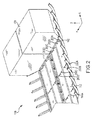
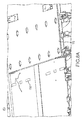
- FIG. 2 illustrates a portion of cargo system 100 including a plurality of cargo restraints in deployed and stowed positions. Cargo restraints allow cargo system 100 to restrain cargo.
- cargo restraints 202 are illustrated in a deployed position and cargo restraints 200 are illustrated in a stowed position.
- air cushion cargo shuttle 102 may move forward or aft over cargo restraints 200 without being restrained by cargo restraints 200 or allowing a significant amount of air to escape the volume beneath air cushion cargo shuttle 102.
- cargo restraints 200 are stowed, air cushion cargo shuttle 102 may transport cargo 108 over cargo restraints 200 to a desired location on floor panel 112.
- air blowers of air cushion cargo shuttle 102 may decrease such that air cushion cargo shuttle 102 and cargo 108 move towards floor panel 112 (i.e., in the negative Z direction).
- cargo 108 may contact and rest on floor panel 112 or on support beams of cargo system 100.
- air cushion cargo shuttle 102 may be moved forward or aft away from cargo 108.
- Cargo restraints 202 may then be deployed in order to restrain cargo 108.
- FIG. 3 illustrates a portion of cargo system 100 as viewed along the Y axis.
- cargo system 100 includes support structure 304, which may include support beams.
- Support structure 304 may be positioned below floor panel 112 (i.e., in the negative Z direction from floor panel 112), above floor panel 112 or on the same plane as floor panel 112.
- Support structure 304 may be designed to support the weight of cargo 108 (i.e., resist forces applied by cargo 108).
- Cargo restraint 202A may include a restraint surface 300A and a longitudinal restraint rod 302A. While cargo restraint 202A is stowed, longitudinal restraint rod 302A may be positioned below floor panel 112 in the Z direction or on the same plane as floor panel 112 and restraint surface 300A may be substantially positioned on the same plane as floor panel 112 such that cargo restraint 202A will not interfere with movement of air cushion cargo shuttle 102 or cause significant leakage of air from volume beneath air cushion cargo shuttle 102.
- restraint surface 300A may extend in the forward and aft directions (i.e., the negative X and the positive X directions) from longitudinal restraint rod 302A. In various embodiments, restraint surface 300A may extend only in the forward direction or only in the aft direction from longitudinal restraint rod 302A.
- cargo 108 may include a notch 110.
- cargo 108 is supported by a cargo pallet that includes a notch.
- Restraint surface 300A may be adapted to be received by notch 110 of cargo 108.
- cargo restraint 202A may restrict the motion of cargo 108, such as restraining cargo 108 from motion in the aft (negative X) direction and the vertical (positive Z) direction.
- a motive force may be provided to translate cargo restraint 202A in the Z direction from a deployed state, as illustrated, to a stowed state, and from the stowed state to the deployed state.
- longitudinal restraint rod 302 may slideably engage a cylindrical opening in support structure 304.
- cargo restraint 202A may translate into and out of support structure 304 in response to a motive force.
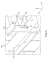
- Deployment guide 400 may engage a feature, as illustrated in FIG. 5 , to rotate restraint surface 300A in the X-Y plane.
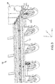
- a cargo restraint system 520 having a deployment guide 505 formed on longitudinal restraint rod 503 and a deployment guide pin 514 configured to engage deployment guide 505.
- Deployment guide pin 514 and deployment guide 505 may position restraint surface 501 and tie-off clevis 502 in a desired angular position about the Z axis.
- Deployment guide 505 may include a straight portion 504A and a twist portion 504B.
- Deployment guide pin 514 may be coupled to a fixed support structure (e.g., support structure 304 of FIG. 4 ) such that movement of deployment guide pin 514 is restrained.
- deployment guide pin 514 In response to cargo restraint 202A being in a stowed position, deployment guide pin 514 may be received by straight portion 504A.
- deployment guide pin 514 may prevent cargo restraint 500 from rotating about the Z axis by engaging straight portion 504A.
- An actuator 516 may provide a motive force to translate cargo restraint 500 in the Z direction.
- deployment guide pin 514 In response to longitudinal restraint rod 503 translating in the Z direction, deployment guide pin 514 may slideably engage a length of twist portion 504B. Cargo restraint 500 may then rotate about the Z in response to deployment guide pin 514 slideably engaging a length of twist portion 504B. Because deployment guide pin 514 is coupled to a support structure (e.g., support structure 304 of FIG. 3 ), its position relative to floor panel 112 (of FIG. 1 ) may be fixed.
- a support structure e.g., support structure 304 of FIG. 3
- Cargo restraint 500 may rotate about the Z axis over an arc length determined by the rotational displacement of twist portion 504B about longitudinal restraint rod 503. Restraint surface 501 may rotate a predetermined amount based on the circumferential component of twist portion 504B.
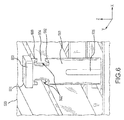
- cargo restraint system 520 is shown with tie-off clevises 502 formed in longitudinal restraint rod 503 of cargo restraint 500, in accordance with various embodiments.
- Tie-off clevis 502 and cargo restraint 500 may be manufactured using additive manufacturing, etching, casting, forging or any other method of manufacturing.
- Tie-off clevis 502 may engage belts, cables, nets, ropes, hooks, or the like to restrain cargo.
- additional restraint of cargo may be desirable in addition to restraint surface 501.
- operators may wish to use ropes to tie down cargo.
- Tie-off clevis 502 may couple the rope to cargo restraint 500 to restrain cargo during travel.
- tie-off clevis 502 may be defined by a wall of longitudinal restraint rod 503. In various embodiments, tie-off clevises 502 may be positioned on either side of restraint surface 501 and deployment guide 505. Tie-off clevis 502 may include an upper protrusion 600 and a lower protrusion 602 that overhang to define area 604. Area 604 may receive a cargo hook, rope, cable, net, or other suitable ties for tying down cargo. Upper protrusion 600 and lower protrusion 602 may restrict motion of the ties such that the ties may be retained in area 604 of tie-off clevis 502.
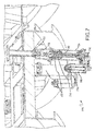
- Cargo restraint deployment system 700 may comprise an actuator 702 mechanically coupled to a cargo restraint 722 to provide motive force to cargo restraint 722.
- Cargo restraint 722 may be the same as cargo restraints 200 and 202 from FIG. 2 .
- Cargo restraint deployment system 700 is illustrated with cargo restraint 722 in a deployed position.
- actuator 702 may comprise housing 704 retaining internal components of actuator 702.
- Actuator 702 may be an electromechanical actuator comprising actuator drive motor 708.
- Actuator drive motor 708 may include a rotor magnetically coupled to a stator with rotary position sensor 706 monitoring the position of the rotor relative to the stator.
- Actuator drive motor 708 may provide rotary energy to gear box 710.
- Gear box 710 may rotate ball screw 712 to move ball spline nut 714 relative to ball screw 712.
- Linear position sensor 716 may monitor the position of ball spline nut 714 about ball screw 712 to determine whether cargo restraint 722 is in a deployed, stowed, or intermediate position.
- actuator 702 may also be a pneumatic or hydraulic piston or other source of controlled linear motion.
- ball spline nut 714 may be coupled to swivel structure 718.
- cargo restraint 722 may rotate in addition to translating linearly during deployment.
- Swivel structure 718 may allow cargo restraint 722 to rotate while ball spline nut 714 remains in linear translation.
- cargo restraint 722 may rotate at a different rate than ball spline nut 714 in response to linear translation.
- Proximity sensors 720 may be in electronic communication with actuator 702 directly and/or through a master control unit. Actuator 702 may be commanded to translate in response to input from proximity sensors 720.
- restraint deployment system 800 is shown with proximity sensors 720 disposed in floor panel 112 with air cushion cargo sled 102 approaching cargo restraint 722, in accordance with various embodiments.
- Proximity sensors 720 may be optical, ultrasonic, and/or electromagnetic sensors configured to detect a position of air cushion cargo sled 102 along floor panels 112.
- Proximity sensors 720 may detect position and/or movement of air cushion cargo sled 112.
- a controller may monitor the change in position over time to detect motion.
- air cushion cargo sled 112 is illustrated as hovering on an air film, proximity sensors 720 and restraint deployment system 800 may also be used in conjunction with rolling, sliding, or otherwise moving cargo sleds.
- proximity sensors 720 may detect the position of air cushion cargo sled 102.
- Cargo restraint 722 may stow in response to air cushion cargo sled 102 moving within a threshold distance of proximity sensors 720.
- restraint deployment system 800 is shown with proximity sensors 720 disposed in floor panel 112 with air cushion cargo sled 102 moving away from cargo restraint 722, in accordance with various embodiments.
- Air cushion cargo sled 102 may be departing cargo restraints 722 after having passed over cargo restraints 722 in a stowed position (as shown in FIG. 8A ).
- Proximity sensors 720 may detect the position of air cushion cargo sled 102 as the sled moves away from cargo restraints 722.
- Cargo restraints 722 may deploy in response to air cushion cargo sled 102 moving outside of a threshold distance from cargo restraints 722.
- restraint deployment system 800 may automatically stow and deploy cargo restraints in response to movement of air cushion cargo sled 102. Air cushion cargo sled 102 may thus move unimpeded by cargo restraints 722.
- the deployment and stow command may also be issued manually by a controller in communication with a fixed or hand held control panel operated by a user.
- a hand held control panel may be connected via wired or wireless communications to restraint deployment system 800.
- cargo restraint 722 may rest with restraint surface (e.g., restraint surface 501 of FIG. 5 ) flush with floor panel 112 or recessed slightly within floor panel 112 when in a stowed position.
- restraint surface e.g., restraint surface 501 of FIG. 5
- cargo restraint 722 in a stowed position may enable air cushion cargo sled 102 to pass over cargo restraint 722 despite having little clearance between air cushion cargo sled 102 and floor panel 112.
- proximity sensors may be flush with floor panel 112 or slightly recessed in floor panel 112.
- Cargo restraint 722 may also protrude from floor panel 112 when in a deployed position to inhibit movement of air cushion cargo sled 102 and/or cargo.
- the electronically actuated cargo restraints of the present disclosure enable automatic retraction and deployment of the cargo restraints.
- Automatic deployment of the cargo restraints may tend to reduce load and/or unload times by allowing an air cushion cargo sled to pass without stopping and/or with little delay.
- the proximity sensors enable automated retraction and/or deployment absent direct user control. The sensors may also notify a user so that the user may manually retract and/or deploy cargo restraints as desired.
- references to "one embodiment”, “an embodiment”, “various embodiments”, etc. indicate that the embodiment described may include a particular feature, structure, or characteristic, but every embodiment may not necessarily include the particular feature, structure, or characteristic. Moreover, such phrases are not necessarily referring to the same embodiment. Further, when a particular feature, structure, or characteristic is described in connection with an embodiment, it is submitted that it is within the knowledge of one skilled in the art to affect such feature, structure, or characteristic in connection with other embodiments whether or not explicitly described. After reading the description, it will be apparent to one skilled in the relevant art(s) how to implement the disclosure in alternative embodiments.
Landscapes
- Engineering & Computer Science (AREA)
- Mechanical Engineering (AREA)
- Aviation & Aerospace Engineering (AREA)
- Transportation (AREA)
- Vibration Dampers (AREA)
- Floor Finish (AREA)
- Transmission Devices (AREA)
Abstract
Description
- The present disclosure relates to a conformal cargo restraint mechanism in a cargo system.
- Conventional aircraft cargo systems typically include various tracks and rollers that span the length of an aircraft. Power drive units ("PDUs") convey cargo forward and aft along the aircraft on conveyance rollers which are attached to the aircraft floor structure. Cargo may be loaded from an aft position on an aircraft and conducted by the cargo system to a forward position and/or, depending upon aircraft configuration, cargo may be loaded from a forward position on an aircraft and conducted by the cargo system to an aft position. Conventional systems are typically designed to accommodate a particular pallet size. Conventional systems are typically comprised of numerous components that may be time consuming to install, replace and maintain.
- Once cargo is loaded into a cargo system, cargo may be restrained for flight. The cargo may be fixed in place by ties or other restraints, for example. Manually deploying restraints to retain loaded cargo pallets may be time consuming and rely on user intervention.
- The foregoing features and elements may be combined in various combinations without exclusivity, unless expressly indicated otherwise. These features and elements as well as the operation thereof will become more apparent in light of the following description and the accompanying drawings. It should be understood, however, the following description and drawings are intended to be exemplary in nature and non-limiting.
- A cargo system may comprise a floor panel, a cargo sled configured to move across the floor panel, and a cargo restraint configured to translate relative to the floor panel. The cargo restraint may comprise a longitudinal restraint rod configured to protrude from the floor panel in a deployed position. The cargo restraint may also comprise a restraint surface disposed on the longitudinal restraint rod. The cargo restraint may enable the cargo sled to pass over the restraint surface in a stowed position. An electromechanical actuator may be mechanically coupled to the longitudinal restraint rod and configured to deploy and stow the cargo restraint.
- In various embodiments, the restraint surface may be configured to lie flush with the floor panel or recessed within the floor panel in the stowed position. A position sensor may be in communication with the electromechanical actuator with the electromechanical actuator configured to stow the cargo restraint in response to the position sensor detecting a motion of the cargo sled towards the cargo restraint. The electromechanical actuator may also be configured to deploy the cargo restraint in response to the position sensor detecting a motion of the cargo sled away from the cargo restraint. A tie-off clevis may be defined by the longitudinal restraint rod. The restraint surface may be configured to be received by a notch of a cargo. A deployment guide may be disposed on the longitudinal restraint rod. A deployment guide pin may be configured to slideably engage the deployment guide. The cargo restraint may rotate in response to the deployment guide pin slideably engaging the deployment guide. A swivel structure may be coupled between the electromechanical actuator and the cargo restraint to allow the cargo restraint to rotate independent from the electromechanical actuator.
- A cargo system may comprise a support structure configured to support a cargo and a cargo restraint coupled to the support structure. The cargo restraint may comprise a longitudinal restraint rod configured to engage the support structure, a restraint surface disposed on the longitudinal restraint rod, and an electromechanical actuator coupled to the longitudinal restraint rod. The electromechanical actuator may deploy and stow the cargo restraint.
- In various embodiments, a floor panel may be disposed over the support structure, and the restraint surface may be configured to be flush with the floor panel and/or recessed in the floor panel in response to the cargo restraint being in a stowed position. A position sensor may be in communication with the electromechanical actuator with the electromechanical actuator configured to stow the cargo restraint in response to the position sensor detecting a motion of the cargo sled towards the cargo restraint. The electromechanical actuator may also be configured to deploy the cargo restraint in response to the position sensor detecting a motion of the cargo sled away from the cargo restraint. A deployment guide may be disposed on the longitudinal restraint rod. A deployment guide pin may be configured to slideably engage the deployment guide. The cargo restraint may rotate in response to the deployment guide pin slideably engaging the deployment guide.
- A cargo restraint may comprise a longitudinal restraint rod, a restraint surface disposed on the longitudinal restraint rod, and an electromechanical actuator coupled to the longitudinal restraint rod opposite the restraint surface. The electromechanical actuator may be configured to translate the longitudinal restraint rod along an axis of the longitudinal restraint rod.
- In various embodiments, a deployment guide may be disposed on the longitudinal restraint rod. The longitudinal restraint rod may also be configured to rotate about the axis in response to a pin slideably engaging the deployment guide. A tie-off clevis may be disposed on the longitudinal restraint rod.
- The subject matter of the present disclosure is particularly pointed out and distinctly claimed in the concluding portion of the specification. A more complete understanding of the present disclosure, however, may best be obtained by referring to the detailed description and claims when considered in connection with the drawing figures.
-
FIG. 1 illustrates an aircraft cargo system, in accordance with various embodiments; -
FIG. 2 illustrates a portion of a cargo system including a plurality of cargo restraints in deployed and stowed positions, in accordance with various embodiments; -
FIG. 3 illustrates a portion of a cargo system, in accordance with various embodiments; -
FIG. 4 illustrates a portion of a cargo system including a deployment guide for rotating a restraint in response to stowing and deploying the restraint as viewed from above a support member with a floor panel cutaway, in accordance with various embodiments; -
FIG. 5 illustrates a portion of a cargo system including a deployment guide for rotating a restraint in response to stowing and deploying the restraint as viewed through a cutaway support member and floor panel, in accordance with various embodiments; -
FIG. 6 illustrates a portion of a cargo system with a cargo restraint in a deployed position, in accordance with various embodiments; -
FIG. 7 illustrates a portion of a cargo system having a cargo restraint mechanically coupled to an electromechanical actuator, in accordance with various embodiments; -
FIG. 8A illustrates a portion of a cargo system having cargo restraints in a stowed position in response to a cargo sled approaching the cargo restraints, in accordance with various embodiments; and -
FIG. 8B illustrates a portion of a cargo system having cargo restraints in a deployed position in response to a cargo sled passing out of a range of the cargo restraints, in accordance with various embodiments. - The detailed description of various embodiments herein makes reference to the accompanying drawings, which show various embodiments by way of illustration. While these various embodiments are described in sufficient detail to enable those skilled in the art to practice the disclosure, it should be understood that other embodiments may be realized and that logical, chemical, and mechanical changes may be made without departing from the spirit and scope of the disclosure. Thus, the detailed description herein is presented for purposes of illustration only and not of limitation. For example, the steps recited in any of the method or process descriptions may be executed in any order and are not necessarily limited to the order presented. Furthermore, any reference to singular includes plural embodiments, and any reference to more than one component or step may include a singular embodiment or step. Also, any reference to attached, fixed, connected, or the like may include permanent, removable, temporary, partial, full, and/or any other possible attachment option.
- As used herein, "aft" refers to the direction associated with the tail of an aircraft, or generally, to the direction of exhaust of the gas turbine engine. As used herein, "forward" refers to the direction associated with the nose of an aircraft, or generally, to the direction of flight or motion.
- Aircraft cargo management systems as disclosed herein allow cargo to be loaded into an aircraft and positioned within the aircraft in a simple, elegant manner. In that regard, aircraft cargo management systems as disclosed herein may reduce part count and associated replacement/wear costs over time.
- With reference to
FIG. 1 , anaircraft cargo system 100 is illustrated. Throughout the FIGs., X-Y-Z axes are shown for ease of illustration.Cargo system 100 includes an aftshuttle drive unit 106A coupled to anaft propulsion belt 104A.Aft propulsion belt 104A is coupled to an aircushion cargo shuttle 102.Cargo system 100 also includes a forwardshuttle drive unit 106B coupled to aforward propulsion belt 104B.Forward propulsion belt 104B is also coupled to aircushion cargo shuttle 102.Cargo system 100 also includes afloor panel 112. - Air
cushion cargo shuttle 102 may include a controller and air blowers. The air blowers may be configured to direct a fluid, such as air, into a volume beneath aircushion cargo shuttle 102. The directed air may result in relatively high pressure (e.g., an air pressure higher than ambient air pressure) in the volume beneath aircushion cargo shuttle 102. This air pressure may cause aircushion cargo shuttle 102 to lift above floor panel 112 (i.e., displace aircushion cargo shuttle 102 in the positive Z direction). Accordingly, it may be desirable forfloor panel 112 to be relatively flat so air within the volume below aircushion cargo shuttle 102 is not released into the atmosphere. The controller may control an amount of air displaced via air blowers in order to alter the pressure beneath aircushion cargo shuttle 102, changing the distance that aircushion cargo shuttle 102 is lifted abovefloor panel 112, or allowing air cushion cargo shuttle to liftcargo 108. - Air
cushion cargo shuttle 102 may be coupled toaft propulsion belt 104A and/orforward propulsion belt 104B. Tension may be applied toaft propulsion belt 104A and/orforward propulsion belt 104B. In response to sufficient tension applied to either propulsion belt, aircushion cargo shuttle 102 may be displaced forward and/or aft. - The propulsion belts may be wound around a portion of aft
shuttle drive unit 106A or forwardshuttle drive unit 106B. In that regard, a shuttle drive unit may comprise a cylindrical structure (e.g., a bobbin) to which a shuttle belt is affixed. The shuttle drive unit comprises a motive device, such as an electric motor, to rotate the bobbin in a desired direction. The shuttle drive unit may also disengage the electric motor or be otherwise geared in such a manner so that free rotation of the bobbin is allowed. Thus, as forwardshuttle drive unit 106B may be rotating its bobbin to pullforward propulsion belt 104B forward, aftshuttle drive unit 106A may allow its bobbin to freely rotate in response to the force exerted byforward propulsion belt 104B through aircushion cargo shuttle 102. In like manner, as aftshuttle drive unit 106A may be rotating its bobbin to pullaft propulsion belt 104A aft, forwardshuttle drive unit 106B may allow its bobbin to rotate in response to a predetermined level of tension exerted byaft propulsion belt 104A through aircushion cargo shuttle 102. - In order to reposition
cargo 108 withincargo system 100, the air blowers of aircushion cargo shuttle 102 may displace a first amount of air, causing aircushion cargo shuttle 102 to lift abovefloor panel 112. In various embodiments, aircushion cargo shuttle 102 is not lifted abovefloor panel 112 prior to being positioned beneathcargo 108. While aircushion cargo shuttle 102 is being lifted by air blowers, forwardshuttle drive unit 106B may become engaged and exert pressure on aircushion cargo shuttle 102 via tension applied to forwardpropulsion belt 104B. Aircushion cargo shuttle 102 may then be displaced forward such that it is positioned beneathcargo 108. In response to aircushion cargo shuttle 102 becoming positioned beneathcargo 108, force applied by forwardshuttle drive unit 106B may be reduced and/or force may be applied via aftshuttle drive unit 106A causing aircushion cargo shuttle 102 to remain positioned beneathcargo 108. - While air
cushion cargo shuttle 102 is positioned beneathcargo 108, the controller of aircushion cargo shuttle 102 may instruct the air blowers to increase the displacement of air beneath aircushion cargo shuttle 102, causing aircushion cargo shuttle 102 to be displaced further fromfloor panel 112, thus liftingcargo 108. Whencargo 108 is lifted abovefloor panel 112, aircushion cargo shuttle 102 may be moved forward and/or aft based on tension applied toaft propulsion belt 104A and/orforward propulsion belt 104B, without friction forces restricting the movement of aircushion cargo shuttle 102. - While an aircraft is in motion, forces may be applied to
cargo 108 from, for example, changes in acceleration in any direction. In order to prevent damage tocargo 108 caused by these forces, it is desirable to be able to restraincargo 108 tofloor panel 112.FIG. 2 illustrates a portion ofcargo system 100 including a plurality of cargo restraints in deployed and stowed positions. Cargo restraints allowcargo system 100 to restrain cargo. - In
FIG. 2 , cargo restraints 202 are illustrated in a deployed position and cargo restraints 200 are illustrated in a stowed position. With reference toFIGs. 1 and2 , when cargo restraints 200 are in a stowed position, aircushion cargo shuttle 102 may move forward or aft over cargo restraints 200 without being restrained by cargo restraints 200 or allowing a significant amount of air to escape the volume beneath aircushion cargo shuttle 102. While cargo restraints 200 are stowed, aircushion cargo shuttle 102 may transportcargo 108 over cargo restraints 200 to a desired location onfloor panel 112. Whencargo 108 is in the desired location, the air blowers of aircushion cargo shuttle 102 may decrease such that aircushion cargo shuttle 102 andcargo 108 move towards floor panel 112 (i.e., in the negative Z direction). In response to aircushion cargo shuttle 102 reaching a predetermined distance fromfloor panel 112,cargo 108 may contact and rest onfloor panel 112 or on support beams ofcargo system 100. Whilecargo 108 is in a resting position, aircushion cargo shuttle 102 may be moved forward or aft away fromcargo 108. Cargo restraints 202 may then be deployed in order to restraincargo 108. -
FIG. 3 illustrates a portion ofcargo system 100 as viewed along the Y axis. As shown,cargo system 100 includessupport structure 304, which may include support beams.Support structure 304 may be positioned below floor panel 112 (i.e., in the negative Z direction from floor panel 112), abovefloor panel 112 or on the same plane asfloor panel 112.Support structure 304 may be designed to support the weight of cargo 108 (i.e., resist forces applied by cargo 108). -
Cargo restraint 202A may include arestraint surface 300A and alongitudinal restraint rod 302A. Whilecargo restraint 202A is stowed,longitudinal restraint rod 302A may be positioned belowfloor panel 112 in the Z direction or on the same plane asfloor panel 112 andrestraint surface 300A may be substantially positioned on the same plane asfloor panel 112 such thatcargo restraint 202A will not interfere with movement of aircushion cargo shuttle 102 or cause significant leakage of air from volume beneath aircushion cargo shuttle 102. - While
cargo restraint 202A is in the deployed state,restraint surface 300A may extend in the forward and aft directions (i.e., the negative X and the positive X directions) fromlongitudinal restraint rod 302A. In various embodiments,restraint surface 300A may extend only in the forward direction or only in the aft direction fromlongitudinal restraint rod 302A. - In various embodiments,
cargo 108 may include anotch 110. In various embodiments,cargo 108 is supported by a cargo pallet that includes a notch.Restraint surface 300A may be adapted to be received bynotch 110 ofcargo 108. In response tocargo restraint 202A being deployed andrestraint surface 300A being received bynotch 110,cargo restraint 202A may restrict the motion ofcargo 108, such as restrainingcargo 108 from motion in the aft (negative X) direction and the vertical (positive Z) direction. - With reference to
FIG. 4 , a portion ofcargo system 100 including adeployment guide 400 for deploying and/or stowingcargo restraint 202A is shown, in accordance with various embodiments. A motive force may be provided to translatecargo restraint 202A in the Z direction from a deployed state, as illustrated, to a stowed state, and from the stowed state to the deployed state. As the cargo restraint 202 translates between stowed and deployed states,longitudinal restraint rod 302 may slideably engage a cylindrical opening insupport structure 304. In that regard,cargo restraint 202A may translate into and out ofsupport structure 304 in response to a motive force.Deployment guide 400 may engage a feature, as illustrated inFIG. 5 , to rotaterestraint surface 300A in the X-Y plane. - With reference to
FIG. 5 , acargo restraint system 520 is shown having adeployment guide 505 formed onlongitudinal restraint rod 503 and adeployment guide pin 514 configured to engagedeployment guide 505.Deployment guide pin 514 anddeployment guide 505 may positionrestraint surface 501 and tie-off clevis 502 in a desired angular position about the Z axis.Deployment guide 505 may include astraight portion 504A and atwist portion 504B.Deployment guide pin 514 may be coupled to a fixed support structure (e.g.,support structure 304 ofFIG. 4 ) such that movement ofdeployment guide pin 514 is restrained. In response tocargo restraint 202A being in a stowed position,deployment guide pin 514 may be received bystraight portion 504A. - In various embodiments,
deployment guide pin 514 may preventcargo restraint 500 from rotating about the Z axis by engagingstraight portion 504A. Anactuator 516 may provide a motive force to translatecargo restraint 500 in the Z direction. In response tolongitudinal restraint rod 503 translating in the Z direction,deployment guide pin 514 may slideably engage a length oftwist portion 504B.Cargo restraint 500 may then rotate about the Z in response todeployment guide pin 514 slideably engaging a length oftwist portion 504B. Becausedeployment guide pin 514 is coupled to a support structure (e.g.,support structure 304 ofFIG. 3 ), its position relative to floor panel 112 (ofFIG. 1 ) may be fixed.Cargo restraint 500 may rotate about the Z axis over an arc length determined by the rotational displacement oftwist portion 504B aboutlongitudinal restraint rod 503.Restraint surface 501 may rotate a predetermined amount based on the circumferential component oftwist portion 504B. - With reference to
FIG. 6 ,cargo restraint system 520 is shown with tie-off clevises 502 formed inlongitudinal restraint rod 503 ofcargo restraint 500, in accordance with various embodiments. Tie-offclevis 502 andcargo restraint 500 may be manufactured using additive manufacturing, etching, casting, forging or any other method of manufacturing. Tie-offclevis 502 may engage belts, cables, nets, ropes, hooks, or the like to restrain cargo. With reference toFIGs. 1 and6 , when cargo is in a position onfloor panel 112, additional restraint of cargo may be desirable in addition torestraint surface 501. For example, operators may wish to use ropes to tie down cargo. Tie-offclevis 502 may couple the rope tocargo restraint 500 to restrain cargo during travel. - In various embodiments, tie-
off clevis 502 may be defined by a wall oflongitudinal restraint rod 503. In various embodiments, tie-off clevises 502 may be positioned on either side ofrestraint surface 501 anddeployment guide 505. Tie-offclevis 502 may include anupper protrusion 600 and a lower protrusion 602 that overhang to definearea 604.Area 604 may receive a cargo hook, rope, cable, net, or other suitable ties for tying down cargo.Upper protrusion 600 and lower protrusion 602 may restrict motion of the ties such that the ties may be retained inarea 604 of tie-off clevis 502. - With reference to
FIG. 7 , a cargorestraint deployment system 700 is shown, in accordance with various embodiments. Cargorestraint deployment system 700 may comprise anactuator 702 mechanically coupled to acargo restraint 722 to provide motive force tocargo restraint 722.Cargo restraint 722 may be the same as cargo restraints 200 and 202 fromFIG. 2 . Cargorestraint deployment system 700 is illustrated withcargo restraint 722 in a deployed position. - In various embodiments,
actuator 702 may comprisehousing 704 retaining internal components ofactuator 702.Actuator 702 may be an electromechanical actuator comprisingactuator drive motor 708.Actuator drive motor 708 may include a rotor magnetically coupled to a stator withrotary position sensor 706 monitoring the position of the rotor relative to the stator.Actuator drive motor 708 may provide rotary energy togear box 710.Gear box 710 may rotate ball screw 712 to moveball spline nut 714 relative toball screw 712.Linear position sensor 716 may monitor the position ofball spline nut 714 aboutball screw 712 to determine whethercargo restraint 722 is in a deployed, stowed, or intermediate position. Although an electromechanical actuator is shown,actuator 702 may also be a pneumatic or hydraulic piston or other source of controlled linear motion. - In various embodiments,
ball spline nut 714 may be coupled to swivelstructure 718. As illustrated inFIGs. 4-6 ,cargo restraint 722 may rotate in addition to translating linearly during deployment.Swivel structure 718 may allowcargo restraint 722 to rotate whileball spline nut 714 remains in linear translation. In that regard,cargo restraint 722 may rotate at a different rate thanball spline nut 714 in response to linear translation.Proximity sensors 720 may be in electronic communication withactuator 702 directly and/or through a master control unit.Actuator 702 may be commanded to translate in response to input fromproximity sensors 720. - With reference to
FIG. 8A .restraint deployment system 800 is shown withproximity sensors 720 disposed infloor panel 112 with aircushion cargo sled 102 approachingcargo restraint 722, in accordance with various embodiments.Proximity sensors 720 may be optical, ultrasonic, and/or electromagnetic sensors configured to detect a position of aircushion cargo sled 102 alongfloor panels 112.Proximity sensors 720 may detect position and/or movement of aircushion cargo sled 112. In various embodiments, a controller may monitor the change in position over time to detect motion. Although aircushion cargo sled 112 is illustrated as hovering on an air film,proximity sensors 720 andrestraint deployment system 800 may also be used in conjunction with rolling, sliding, or otherwise moving cargo sleds. As aircushion cargo sled 102 approachescargo restraint 722,proximity sensors 720 may detect the position of aircushion cargo sled 102.Cargo restraint 722 may stow in response to aircushion cargo sled 102 moving within a threshold distance ofproximity sensors 720. - With reference to
FIG. 8B ,restraint deployment system 800 is shown withproximity sensors 720 disposed infloor panel 112 with aircushion cargo sled 102 moving away fromcargo restraint 722, in accordance with various embodiments. Aircushion cargo sled 102 may be departingcargo restraints 722 after having passed overcargo restraints 722 in a stowed position (as shown inFIG. 8A ).Proximity sensors 720 may detect the position of aircushion cargo sled 102 as the sled moves away fromcargo restraints 722.Cargo restraints 722 may deploy in response to aircushion cargo sled 102 moving outside of a threshold distance fromcargo restraints 722. In that regard,restraint deployment system 800 may automatically stow and deploy cargo restraints in response to movement of aircushion cargo sled 102. Aircushion cargo sled 102 may thus move unimpeded bycargo restraints 722. The deployment and stow command may also be issued manually by a controller in communication with a fixed or hand held control panel operated by a user. A hand held control panel may be connected via wired or wireless communications torestraint deployment system 800. - In various embodiments,
cargo restraint 722 may rest with restraint surface (e.g.,restraint surface 501 ofFIG. 5 ) flush withfloor panel 112 or recessed slightly withinfloor panel 112 when in a stowed position. In that regard,cargo restraint 722 in a stowed position may enable aircushion cargo sled 102 to pass overcargo restraint 722 despite having little clearance between aircushion cargo sled 102 andfloor panel 112. Similarly, proximity sensors may be flush withfloor panel 112 or slightly recessed infloor panel 112.Cargo restraint 722 may also protrude fromfloor panel 112 when in a deployed position to inhibit movement of aircushion cargo sled 102 and/or cargo. - The electronically actuated cargo restraints of the present disclosure enable automatic retraction and deployment of the cargo restraints. Automatic deployment of the cargo restraints may tend to reduce load and/or unload times by allowing an air cushion cargo sled to pass without stopping and/or with little delay. The proximity sensors enable automated retraction and/or deployment absent direct user control. The sensors may also notify a user so that the user may manually retract and/or deploy cargo restraints as desired.
- Benefits, other advantages, and solutions to problems have been described herein with regard to specific embodiments. Furthermore, the connecting lines shown in the various figures contained herein are intended to represent exemplary functional relationships and/or physical couplings between the various elements. It should be noted that many alternative or additional functional relationships or physical connections may be present in a practical system. However, the benefits, advantages, solutions to problems, and any elements that may cause any benefit, advantage, or solution to occur or become more pronounced are not to be construed as critical, required, or essential features or elements of the disclosure. The scope of the disclosure is accordingly to be limited by nothing other than the appended claims, in which reference to an element in the singular is not intended to mean "one and only one" unless explicitly so stated, but rather "one or more." Moreover, where a phrase similar to "at least one of A, B, or C" is used in the claims, it is intended that the phrase be interpreted to mean that A alone may be present in an embodiment, B alone may be present in an embodiment, C alone may be present in an embodiment, or that any combination of the elements A, B and C may be present in a single embodiment; for example, A and B, A and C, B and C, or A and B and C. Different cross-hatching is used throughout the figures to denote different parts but not necessarily to denote the same or different materials.
- Systems, methods and apparatus are provided herein. In the detailed description herein, references to "one embodiment", "an embodiment", "various embodiments", etc., indicate that the embodiment described may include a particular feature, structure, or characteristic, but every embodiment may not necessarily include the particular feature, structure, or characteristic. Moreover, such phrases are not necessarily referring to the same embodiment. Further, when a particular feature, structure, or characteristic is described in connection with an embodiment, it is submitted that it is within the knowledge of one skilled in the art to affect such feature, structure, or characteristic in connection with other embodiments whether or not explicitly described. After reading the description, it will be apparent to one skilled in the relevant art(s) how to implement the disclosure in alternative embodiments.
- Furthermore, no element, component, or method step in the present disclosure is intended to be dedicated to the public regardless of whether the element, component, or method step is explicitly recited in the claims. No claim element herein is to be construed under the provisions of 35 U.S.C. 112(f) unless the element is expressly recited using the phrase "means for.'' As used herein, the terms "comprises", "comprising", or any other variation thereof, are intended to cover a non-exclusive inclusion, such that a process, method, article, or apparatus that comprises a list of elements does not include only those elements but may include other elements not expressly listed or inherent to such process, method, article, or apparatus.
Claims (15)
- A cargo system (100, 520), comprising:a floor panel (112);a cargo sled configured to move across the floor panel;a cargo restraint (200, 202, 500, 722) configured to translate relative to the floor panel (112), the cargo restraint (200, 202, 500, 722) comprising:a longitudinal restraint rod (302, 503) configured to protrude from the floor panel (112) in a deployed position; anda restraint surface (300A, 501) disposed on the longitudinal restraint rod (302, 503), wherein the cargo restraint is configured to enable the cargo sled to pass over the restraint surface in a stowed position; andan electromechanical actuator (702) mechanically coupled to the longitudinal restraint rod (302, 503), wherein the electromechanical actuator (702) is configured to deploy and stow the cargo restraint.
- The cargo system of claim 1, wherein the restraint surface (300A, 501) is configured to lie flush with the floor panel (112) or recessed within the floor panel (112) in the stowed position.
- The cargo system of claim 1 or 2, further comprising a position sensor (706, 716) in communication with the electromechanical actuator (702), wherein the electromechanical actuator (702) is configured to automatically stow the cargo restraint in response to the position sensor (706, 716) detecting a motion of the cargo sled towards the cargo restraint.
- The cargo system of claim 3, wherein the electromechanical actuator (702) is configured to automatically deploy the cargo restraint in response to the position sensor (706, 716) detecting a motion of the cargo sled away from the cargo restraint.
- The cargo system of any preceding claim, further comprising a tie-off clevis defined by the longitudinal restraint rod (302, 503).
- The cargo system of any preceding claim, wherein the restraint surface is configured to be received by a notch of a cargo.
- The cargo system of any preceding claim, further comprising a swivel structure (718) coupled between the electromechanical actuator (702) and the cargo restraint, wherein the swivel structure (718) is configured to allow the cargo restraint to rotate independent from the electromechanical actuator (702).
- A cargo system, comprising:a support structure (304) configured to support a cargo (108);a cargo restraint (200, 202, 500, 722) coupled to the support structure (304) and comprising:a longitudinal restraint rod (302, 503) configured to engage the support structure (304);a restraint surface (300A, 501) disposed on the longitudinal restraint rod (302, 503); andan electromechanical actuator (702) coupled to the longitudinal restraint rod (302, 503), wherein the electromechanical actuator (702) is configured to deploy and stow the cargo restraint.
- The cargo system of claim 8, further comprising a floor panel (112) disposed over the support structure (304), wherein the restraint surface is configured to be at least one of flush with the floor panel (112) or recessed in the floor panel (112) in response to the cargo restraint being in a stowed position.
- The cargo system of claim 8 or 9, further comprising a position sensor (706, 716) in communication with the electromechanical actuator (702), wherein the electromechanical actuator (702) is configured to stow the cargo restraint in response to the position sensor (706, 716) detecting a motion of the cargo sled towards the cargo restraint, and preferably wherein the electromechanical actuator (702) is configured to deploy the cargo restraint in response to the position sensor detecting a motion of the cargo sled away from the cargo restraint.
- The cargo system of any preceding claim, further comprising a deployment guide (400, 505) disposed on the longitudinal restraint rod (302A, 502A).
- The cargo system of claim 11, further comprising a deployment guide pin (514) configured to slideably engage the deployment guide (505), and preferably wherein the cargo restraint is confgured to rotate in response to the deployment guide pin slideably engaging the deployment guide.
- A cargo restraint, comprising:a longitudinal restraint rod (302A, 502A);a restraint surface (300A, 501) disposed on the longitudinal restraint rod (302, 503); andan electromechanical actuator (702) coupled to the longitudinal restraint rod opposite the restraint surface, wherein the electromechanical actuator (702) is configured to translate the longitudinal restraint rod (302, 503) along an axis of the longitudinal restraint rod (302, 503).
- The cargo restraint of claim 13, further comprising a deployment guide (400, 505) disposed on the longitudinal restraint rod, wherein the longitudinal restraint rod (302, 503) is configured to rotate about the axis in response to a pin slideably engaging the deployment guide.
- The cargo restraint of claim 13 or 14, further comprising a tie-off clevis (502) disposed on the longitudinal restraint rod.
Applications Claiming Priority (1)
| Application Number | Priority Date | Filing Date | Title |
|---|---|---|---|
| US14/884,557 US9937997B2 (en) | 2015-10-15 | 2015-10-15 | Conformal actuator operated aircraft cargo restraint mechanism |
Publications (3)
| Publication Number | Publication Date |
|---|---|
| EP3176087A2 true EP3176087A2 (en) | 2017-06-07 |
| EP3176087A3 EP3176087A3 (en) | 2017-08-30 |
| EP3176087B1 EP3176087B1 (en) | 2019-05-08 |
Family
ID=57144864
Family Applications (1)
| Application Number | Title | Priority Date | Filing Date |
|---|---|---|---|
| EP16194098.6A Not-in-force EP3176087B1 (en) | 2015-10-15 | 2016-10-17 | Conformal actuator operated aircraft cargo restraint mechanism |
Country Status (2)
| Country | Link |
|---|---|
| US (1) | US9937997B2 (en) |
| EP (1) | EP3176087B1 (en) |
Families Citing this family (13)
| Publication number | Priority date | Publication date | Assignee | Title |
|---|---|---|---|---|
| US10196146B2 (en) * | 2014-10-10 | 2019-02-05 | Goodrich Corporation | Self propelled air cushion supported aircraft cargo loading systems and methods |
| US10393225B2 (en) | 2015-01-05 | 2019-08-27 | Goodrich Corporation | Integrated multi-function propulsion belt for air cushion supported aircraft cargo loading robot |
| EP3481718A1 (en) * | 2016-07-08 | 2019-05-15 | Creative Solutions, Inc. | Protective covers for use with aircraft cargo holds |
| US11072424B2 (en) * | 2018-02-19 | 2021-07-27 | Goodrich Corporation | Cargo intelligent restraint system |
| CN109572531B (en) | 2018-03-02 | 2024-06-07 | 北京图森智途科技有限公司 | Vehicle for transporting container |
| EP3832424B1 (en) * | 2019-12-02 | 2022-07-13 | Volocopter GmbH | Method of operating an actuator system, actuator system, and aircraft comprising said method and system |
| US11618640B2 (en) * | 2020-04-20 | 2023-04-04 | The Boeing Company | Methods and apparatus to position a cargo unit in a cargo compartment of an aircraft |
| KR20220084474A (en) * | 2020-12-14 | 2022-06-21 | 현대자동차주식회사 | Space division device |
| EP4043335B1 (en) | 2021-02-16 | 2024-11-27 | ABB Schweiz AG | Method and arrangement for sealing a propeller shaft located under water |
| EP4304936A4 (en) * | 2021-03-10 | 2024-12-25 | ZSM Holdings LLC | REMOVABLE CARGO FLOOR SYSTEMS AND METHODS FOR CARGO AIRCRAFT |
| FR3130745A1 (en) * | 2021-12-16 | 2023-06-23 | Airbus Operations | Part of an aircraft comprising a floor linked to a section of the fuselage by means of elastic connecting rods. |
| KR20240080541A (en) * | 2022-11-30 | 2024-06-07 | 현대자동차주식회사 | Mounting unit for upper module of commercial vehicle |
| CN117622011B (en) * | 2024-01-26 | 2024-04-02 | 江苏零浩网络科技有限公司 | Intelligent movable goods position sensor of freight car |
Family Cites Families (27)
| Publication number | Priority date | Publication date | Assignee | Title |
|---|---|---|---|---|
| AT333607B (en) * | 1973-03-13 | 1976-12-10 | Graubremse Gmbh | DEVICE FOR LOCKING A CARGO CONTAINER ON A BASE, IN PARTICULAR A CHASSIS |
| DE2410771A1 (en) | 1974-03-07 | 1975-09-11 | Graubremse Gmbh | Freight container anchoring mechanism - has locking bolt as differential piston sliding in extension of hollow piston |
| JPS523170B2 (en) * | 1974-04-10 | 1977-01-26 | ||
| DE2539081B2 (en) * | 1975-09-03 | 1979-07-05 | Graubremse Gmbh, 6900 Heidelberg | Device for locking a freight container on a base, in particular a chassis |
| US4203372A (en) | 1977-12-14 | 1980-05-20 | Artemov Konstantin V | Container securing device |
| US4375932A (en) | 1981-05-07 | 1983-03-08 | The Boeing Company | Powered cargo restraint |
| DE4136973C2 (en) | 1991-11-11 | 1996-01-18 | Daimler Benz Aerospace Airbus | Load locking device in aircraft |
| US5265991A (en) | 1992-10-30 | 1993-11-30 | Aar Corp. | Retractable cargo restraint and cargo restraining system |
| US5346162A (en) | 1993-11-08 | 1994-09-13 | Lockheed Corporation | Cargo compartment for a lighter-than-air vehicle |
| DE29502421U1 (en) | 1995-02-15 | 1995-03-30 | Willi Wader GmbH, 42477 Radevormwald | Device for lashing containers |
| US5927650A (en) | 1997-07-01 | 1999-07-27 | Telair International Gmbh | Conversion device for installation in an aircraft deck |
| KR100351793B1 (en) * | 2000-01-27 | 2002-09-11 | 금명정밀공업 주식회사 | Auto Locking Apparatus of Container For Trailer |
| US6622640B2 (en) * | 2000-07-14 | 2003-09-23 | Aar Corp. | Airlift pallet for container roll-in/out platform (CROP) |
| US6557800B2 (en) | 2001-09-26 | 2003-05-06 | The Boeing Company | Cargo handling system for aircraft compartments |
| US6695553B1 (en) | 2001-11-28 | 2004-02-24 | Donald E. Galbreath | Device for securing a container to a hoist |
| US6817578B1 (en) * | 2003-04-28 | 2004-11-16 | The Boeing Company | Enhanced aerial delivery system (EADS) platform |
| DE102005008443B4 (en) | 2005-02-24 | 2009-06-18 | Airbus Deutschland Gmbh | Loading device for at least partially automatic loading and unloading of a cargo space of a means of transport |
| NZ540123A (en) | 2005-05-18 | 2006-11-30 | Nathan Paul Strong | Retractable mooring cleat having members extending from surface on divergent paths |
| GB2440062B (en) | 2005-10-13 | 2008-03-12 | Goodrich Corp | Overridable guide and verticle restraint for an air cargo system |
| US7785056B2 (en) | 2006-08-22 | 2010-08-31 | The Boeing Company | Cargo transport system and method |
| FR2916422B1 (en) | 2007-05-25 | 2016-09-30 | Goodrich Corp | METHOD FOR MODIFYING THE CARGO AIRBAR FOR RECEIVING STANDARD PALLETS OF DIFFERENT LENGTHS, KIT OF IMPLEMENTATION AND PLANE SO EQUIPPED |
| US20090121085A1 (en) | 2007-11-13 | 2009-05-14 | Goodrich Corporation | Infrared Communication System for Activating Power Drive Units in an Aircraft Cargo Loading System |
| DE102008052337A1 (en) | 2008-10-20 | 2010-05-12 | Airbus Deutschland Gmbh | Multifunctional cargo compartment system |
| DE102010026559B4 (en) | 2010-07-08 | 2013-11-14 | Wader-Wittis Gmbh | Device for securing heavy loads |
| EP2815970B1 (en) | 2013-06-21 | 2018-04-04 | Airbus Operations GmbH | System and method for loading and unloading a cargo compartment |
| EP2815982B1 (en) | 2013-06-21 | 2018-06-20 | Airbus Operations GmbH | Cargo compartment and method for loading a cargo compartment |
| US20160194082A1 (en) | 2015-01-05 | 2016-07-07 | Goodrich Corporation | Conformal manually operated aircraft cargo restraint mechanism with integrated tie off |
-
2015
- 2015-10-15 US US14/884,557 patent/US9937997B2/en active Active
-
2016
- 2016-10-17 EP EP16194098.6A patent/EP3176087B1/en not_active Not-in-force
Non-Patent Citations (1)
| Title |
|---|
| None |
Also Published As
| Publication number | Publication date |
|---|---|
| EP3176087B1 (en) | 2019-05-08 |
| EP3176087A3 (en) | 2017-08-30 |
| US20170106966A1 (en) | 2017-04-20 |
| US9937997B2 (en) | 2018-04-10 |
Similar Documents
| Publication | Publication Date | Title |
|---|---|---|
| US9937997B2 (en) | Conformal actuator operated aircraft cargo restraint mechanism | |
| EP3040272A1 (en) | Conformal manually operated aircraft cargo restraint mechanism with integrated tie off | |
| EP3492380B1 (en) | Home-delivered article loading device for drone | |
| US9205923B1 (en) | Manual override cargo unloading system for air cushion supported aircraft cargo loading robot | |
| EP2993126B1 (en) | Air cushion aircraft cargo loading system | |
| US9643723B2 (en) | Slide bushing supported aircraft cargo loading systems and methods | |
| CN102791607B (en) | Cable controlled container yoke | |
| EP3006342B1 (en) | Air cushion aircraft cargo loading systems and shuttle drive unit | |
| RU2576396C2 (en) | Actuators for control over flight of structural profile of wing for conversion of wind energy into electric or mechanical power | |
| KR102545827B1 (en) | Drone landing site based vehicle with drone charging system | |
| US9352835B2 (en) | Wedge lift jacking system for crawler supported aircraft loading robot | |
| EP3636581B1 (en) | Cable offset detection with contact | |
| CN106809400B (en) | A vehicle-mounted retractable device for a fixed-wing unmanned aerial vehicle | |
| EP3147248B1 (en) | Braking system for a hoisted structure and method of controlling braking a hoisted strucuture | |
| EP3006287A1 (en) | Pressure compensating air curtain for air cushion supported cargo loading platform | |
| EP3006329A1 (en) | Self propelled air cushion supported aircraft cargo loading systems and methods | |
| US12404047B2 (en) | Drone loading system | |
| US20190263642A1 (en) | Cable guide mechanism for a rescue hoist | |
| CN106184799A (en) | A kind of carrier-borne depopulated helicopter harpoon system | |
| CN110199116A (en) | Wind turbine maintenance or construction method and equipment | |
| JP2001354196A (en) | Heavy article aerial carrying device | |
| EP4553031A1 (en) | Rescue hoist cable foul protection | |
| US3398934A (en) | Cargo winch system | |
| CN119072590A (en) | A braking mechanism, a lifting mechanism and a deployment mechanism for a guide rail chassis of a ship-borne guide rail system | |
| KR101601722B1 (en) | An assist apparatus for slowly turning and dropping of speed of ship |
Legal Events
| Date | Code | Title | Description |
|---|---|---|---|
| AK | Designated contracting states |
Kind code of ref document: A2 Designated state(s): AL AT BE BG CH CY CZ DE DK EE ES FI FR GB GR HR HU IE IS IT LI LT LU LV MC MK MT NL NO PL PT RO RS SE SI SK SM TR |
|
| AX | Request for extension of the european patent |
Extension state: BA ME |
|
| PUAI | Public reference made under article 153(3) epc to a published international application that has entered the european phase |
Free format text: ORIGINAL CODE: 0009012 |
|
| STAA | Information on the status of an ep patent application or granted ep patent |
Free format text: STATUS: THE APPLICATION HAS BEEN PUBLISHED |
|
| PUAL | Search report despatched |
Free format text: ORIGINAL CODE: 0009013 |
|
| AK | Designated contracting states |
Kind code of ref document: A3 Designated state(s): AL AT BE BG CH CY CZ DE DK EE ES FI FR GB GR HR HU IE IS IT LI LT LU LV MC MK MT NL NO PL PT RO RS SE SI SK SM TR |
|
| AX | Request for extension of the european patent |
Extension state: BA ME |
|
| RIC1 | Information provided on ipc code assigned before grant |
Ipc: B64C 1/20 20060101ALI20170727BHEP Ipc: B64D 9/00 20060101AFI20170727BHEP Ipc: B60P 7/15 20060101ALI20170727BHEP |
|
| RIN1 | Information on inventor provided before grant (corrected) |
Inventor name: HIMMELMANN, RICHARD A. |
|
| STAA | Information on the status of an ep patent application or granted ep patent |
Free format text: STATUS: REQUEST FOR EXAMINATION WAS MADE |
|
| 17P | Request for examination filed |
Effective date: 20180228 |
|
| RBV | Designated contracting states (corrected) |
Designated state(s): AL AT BE BG CH CY CZ DE DK EE ES FI FR GB GR HR HU IE IS IT LI LT LU LV MC MK MT NL NO PL PT RO RS SE SI SK SM TR |
|
| STAA | Information on the status of an ep patent application or granted ep patent |
Free format text: STATUS: EXAMINATION IS IN PROGRESS |
|
| 17Q | First examination report despatched |
Effective date: 20180529 |
|
| GRAP | Despatch of communication of intention to grant a patent |
Free format text: ORIGINAL CODE: EPIDOSNIGR1 |
|
| STAA | Information on the status of an ep patent application or granted ep patent |
Free format text: STATUS: GRANT OF PATENT IS INTENDED |
|
| INTG | Intention to grant announced |
Effective date: 20181204 |
|
| GRAS | Grant fee paid |
Free format text: ORIGINAL CODE: EPIDOSNIGR3 |
|
| GRAA | (expected) grant |
Free format text: ORIGINAL CODE: 0009210 |
|
| STAA | Information on the status of an ep patent application or granted ep patent |
Free format text: STATUS: THE PATENT HAS BEEN GRANTED |
|
| AK | Designated contracting states |
Kind code of ref document: B1 Designated state(s): AL AT BE BG CH CY CZ DE DK EE ES FI FR GB GR HR HU IE IS IT LI LT LU LV MC MK MT NL NO PL PT RO RS SE SI SK SM TR |
|
| REG | Reference to a national code |
Ref country code: GB Ref legal event code: FG4D |
|
| REG | Reference to a national code |
Ref country code: CH Ref legal event code: EP Ref country code: AT Ref legal event code: REF Ref document number: 1129752 Country of ref document: AT Kind code of ref document: T Effective date: 20190515 |
|
| REG | Reference to a national code |
Ref country code: DE Ref legal event code: R096 Ref document number: 602016013525 Country of ref document: DE Ref country code: IE Ref legal event code: FG4D |
|
| REG | Reference to a national code |
Ref country code: NL Ref legal event code: MP Effective date: 20190508 |
|
| REG | Reference to a national code |
Ref country code: LT Ref legal event code: MG4D |
|
| PG25 | Lapsed in a contracting state [announced via postgrant information from national office to epo] |
Ref country code: NL Free format text: LAPSE BECAUSE OF FAILURE TO SUBMIT A TRANSLATION OF THE DESCRIPTION OR TO PAY THE FEE WITHIN THE PRESCRIBED TIME-LIMIT Effective date: 20190508 Ref country code: SE Free format text: LAPSE BECAUSE OF FAILURE TO SUBMIT A TRANSLATION OF THE DESCRIPTION OR TO PAY THE FEE WITHIN THE PRESCRIBED TIME-LIMIT Effective date: 20190508 Ref country code: LT Free format text: LAPSE BECAUSE OF FAILURE TO SUBMIT A TRANSLATION OF THE DESCRIPTION OR TO PAY THE FEE WITHIN THE PRESCRIBED TIME-LIMIT Effective date: 20190508 Ref country code: PT Free format text: LAPSE BECAUSE OF FAILURE TO SUBMIT A TRANSLATION OF THE DESCRIPTION OR TO PAY THE FEE WITHIN THE PRESCRIBED TIME-LIMIT Effective date: 20190908 Ref country code: AL Free format text: LAPSE BECAUSE OF FAILURE TO SUBMIT A TRANSLATION OF THE DESCRIPTION OR TO PAY THE FEE WITHIN THE PRESCRIBED TIME-LIMIT Effective date: 20190508 Ref country code: NO Free format text: LAPSE BECAUSE OF FAILURE TO SUBMIT A TRANSLATION OF THE DESCRIPTION OR TO PAY THE FEE WITHIN THE PRESCRIBED TIME-LIMIT Effective date: 20190808 Ref country code: HR Free format text: LAPSE BECAUSE OF FAILURE TO SUBMIT A TRANSLATION OF THE DESCRIPTION OR TO PAY THE FEE WITHIN THE PRESCRIBED TIME-LIMIT Effective date: 20190508 Ref country code: FI Free format text: LAPSE BECAUSE OF FAILURE TO SUBMIT A TRANSLATION OF THE DESCRIPTION OR TO PAY THE FEE WITHIN THE PRESCRIBED TIME-LIMIT Effective date: 20190508 |
|
| PG25 | Lapsed in a contracting state [announced via postgrant information from national office to epo] |
Ref country code: GR Free format text: LAPSE BECAUSE OF FAILURE TO SUBMIT A TRANSLATION OF THE DESCRIPTION OR TO PAY THE FEE WITHIN THE PRESCRIBED TIME-LIMIT Effective date: 20190809 Ref country code: BG Free format text: LAPSE BECAUSE OF FAILURE TO SUBMIT A TRANSLATION OF THE DESCRIPTION OR TO PAY THE FEE WITHIN THE PRESCRIBED TIME-LIMIT Effective date: 20190808 Ref country code: LV Free format text: LAPSE BECAUSE OF FAILURE TO SUBMIT A TRANSLATION OF THE DESCRIPTION OR TO PAY THE FEE WITHIN THE PRESCRIBED TIME-LIMIT Effective date: 20190508 Ref country code: RS Free format text: LAPSE BECAUSE OF FAILURE TO SUBMIT A TRANSLATION OF THE DESCRIPTION OR TO PAY THE FEE WITHIN THE PRESCRIBED TIME-LIMIT Effective date: 20190508 |
|
| REG | Reference to a national code |
Ref country code: AT Ref legal event code: MK05 Ref document number: 1129752 Country of ref document: AT Kind code of ref document: T Effective date: 20190508 |
|
| PG25 | Lapsed in a contracting state [announced via postgrant information from national office to epo] |
Ref country code: AT Free format text: LAPSE BECAUSE OF FAILURE TO SUBMIT A TRANSLATION OF THE DESCRIPTION OR TO PAY THE FEE WITHIN THE PRESCRIBED TIME-LIMIT Effective date: 20190508 Ref country code: EE Free format text: LAPSE BECAUSE OF FAILURE TO SUBMIT A TRANSLATION OF THE DESCRIPTION OR TO PAY THE FEE WITHIN THE PRESCRIBED TIME-LIMIT Effective date: 20190508 Ref country code: DK Free format text: LAPSE BECAUSE OF FAILURE TO SUBMIT A TRANSLATION OF THE DESCRIPTION OR TO PAY THE FEE WITHIN THE PRESCRIBED TIME-LIMIT Effective date: 20190508 Ref country code: SK Free format text: LAPSE BECAUSE OF FAILURE TO SUBMIT A TRANSLATION OF THE DESCRIPTION OR TO PAY THE FEE WITHIN THE PRESCRIBED TIME-LIMIT Effective date: 20190508 Ref country code: CZ Free format text: LAPSE BECAUSE OF FAILURE TO SUBMIT A TRANSLATION OF THE DESCRIPTION OR TO PAY THE FEE WITHIN THE PRESCRIBED TIME-LIMIT Effective date: 20190508 Ref country code: RO Free format text: LAPSE BECAUSE OF FAILURE TO SUBMIT A TRANSLATION OF THE DESCRIPTION OR TO PAY THE FEE WITHIN THE PRESCRIBED TIME-LIMIT Effective date: 20190508 |
|
| REG | Reference to a national code |
Ref country code: DE Ref legal event code: R097 Ref document number: 602016013525 Country of ref document: DE |
|
| PG25 | Lapsed in a contracting state [announced via postgrant information from national office to epo] |
Ref country code: SM Free format text: LAPSE BECAUSE OF FAILURE TO SUBMIT A TRANSLATION OF THE DESCRIPTION OR TO PAY THE FEE WITHIN THE PRESCRIBED TIME-LIMIT Effective date: 20190508 Ref country code: IT Free format text: LAPSE BECAUSE OF FAILURE TO SUBMIT A TRANSLATION OF THE DESCRIPTION OR TO PAY THE FEE WITHIN THE PRESCRIBED TIME-LIMIT Effective date: 20190508 |
|
| PLBE | No opposition filed within time limit |
Free format text: ORIGINAL CODE: 0009261 |
|
| STAA | Information on the status of an ep patent application or granted ep patent |
Free format text: STATUS: NO OPPOSITION FILED WITHIN TIME LIMIT |
|
| PG25 | Lapsed in a contracting state [announced via postgrant information from national office to epo] |
Ref country code: TR Free format text: LAPSE BECAUSE OF FAILURE TO SUBMIT A TRANSLATION OF THE DESCRIPTION OR TO PAY THE FEE WITHIN THE PRESCRIBED TIME-LIMIT Effective date: 20190508 |
|
| 26N | No opposition filed |
Effective date: 20200211 |
|
| PG25 | Lapsed in a contracting state [announced via postgrant information from national office to epo] |
Ref country code: PL Free format text: LAPSE BECAUSE OF FAILURE TO SUBMIT A TRANSLATION OF THE DESCRIPTION OR TO PAY THE FEE WITHIN THE PRESCRIBED TIME-LIMIT Effective date: 20190508 |
|
| PG25 | Lapsed in a contracting state [announced via postgrant information from national office to epo] |
Ref country code: SI Free format text: LAPSE BECAUSE OF FAILURE TO SUBMIT A TRANSLATION OF THE DESCRIPTION OR TO PAY THE FEE WITHIN THE PRESCRIBED TIME-LIMIT Effective date: 20190508 Ref country code: MC Free format text: LAPSE BECAUSE OF FAILURE TO SUBMIT A TRANSLATION OF THE DESCRIPTION OR TO PAY THE FEE WITHIN THE PRESCRIBED TIME-LIMIT Effective date: 20190508 |
|
| REG | Reference to a national code |
Ref country code: CH Ref legal event code: PL |
|
| PG25 | Lapsed in a contracting state [announced via postgrant information from national office to epo] |
Ref country code: LI Free format text: LAPSE BECAUSE OF NON-PAYMENT OF DUE FEES Effective date: 20191031 Ref country code: LU Free format text: LAPSE BECAUSE OF NON-PAYMENT OF DUE FEES Effective date: 20191017 Ref country code: CH Free format text: LAPSE BECAUSE OF NON-PAYMENT OF DUE FEES Effective date: 20191031 |
|
| REG | Reference to a national code |
Ref country code: BE Ref legal event code: MM Effective date: 20191031 |
|
| PG25 | Lapsed in a contracting state [announced via postgrant information from national office to epo] |
Ref country code: BE Free format text: LAPSE BECAUSE OF NON-PAYMENT OF DUE FEES Effective date: 20191031 |
|
| PG25 | Lapsed in a contracting state [announced via postgrant information from national office to epo] |
Ref country code: ES Free format text: LAPSE BECAUSE OF FAILURE TO SUBMIT A TRANSLATION OF THE DESCRIPTION OR TO PAY THE FEE WITHIN THE PRESCRIBED TIME-LIMIT Effective date: 20190508 Ref country code: IE Free format text: LAPSE BECAUSE OF NON-PAYMENT OF DUE FEES Effective date: 20191017 |
|
| PG25 | Lapsed in a contracting state [announced via postgrant information from national office to epo] |
Ref country code: CY Free format text: LAPSE BECAUSE OF FAILURE TO SUBMIT A TRANSLATION OF THE DESCRIPTION OR TO PAY THE FEE WITHIN THE PRESCRIBED TIME-LIMIT Effective date: 20190508 |
|
| GBPC | Gb: european patent ceased through non-payment of renewal fee |
Effective date: 20201017 |
|
| PG25 | Lapsed in a contracting state [announced via postgrant information from national office to epo] |
Ref country code: IS Free format text: LAPSE BECAUSE OF FAILURE TO SUBMIT A TRANSLATION OF THE DESCRIPTION OR TO PAY THE FEE WITHIN THE PRESCRIBED TIME-LIMIT Effective date: 20190908 |
|
| PG25 | Lapsed in a contracting state [announced via postgrant information from national office to epo] |
Ref country code: MT Free format text: LAPSE BECAUSE OF FAILURE TO SUBMIT A TRANSLATION OF THE DESCRIPTION OR TO PAY THE FEE WITHIN THE PRESCRIBED TIME-LIMIT Effective date: 20190508 Ref country code: HU Free format text: LAPSE BECAUSE OF FAILURE TO SUBMIT A TRANSLATION OF THE DESCRIPTION OR TO PAY THE FEE WITHIN THE PRESCRIBED TIME-LIMIT; INVALID AB INITIO Effective date: 20161017 |
|
| PG25 | Lapsed in a contracting state [announced via postgrant information from national office to epo] |
Ref country code: GB Free format text: LAPSE BECAUSE OF NON-PAYMENT OF DUE FEES Effective date: 20201017 |
|
| PG25 | Lapsed in a contracting state [announced via postgrant information from national office to epo] |
Ref country code: MK Free format text: LAPSE BECAUSE OF FAILURE TO SUBMIT A TRANSLATION OF THE DESCRIPTION OR TO PAY THE FEE WITHIN THE PRESCRIBED TIME-LIMIT Effective date: 20190508 |
|
| P01 | Opt-out of the competence of the unified patent court (upc) registered |
Effective date: 20230522 |
|
| PGFP | Annual fee paid to national office [announced via postgrant information from national office to epo] |
Ref country code: FR Payment date: 20230920 Year of fee payment: 8 |
|
| PGFP | Annual fee paid to national office [announced via postgrant information from national office to epo] |
Ref country code: DE Payment date: 20230920 Year of fee payment: 8 |
|
| REG | Reference to a national code |
Ref country code: DE Ref legal event code: R119 Ref document number: 602016013525 Country of ref document: DE |
|
| PG25 | Lapsed in a contracting state [announced via postgrant information from national office to epo] |
Ref country code: DE Free format text: LAPSE BECAUSE OF NON-PAYMENT OF DUE FEES Effective date: 20250501 |
|
| PG25 | Lapsed in a contracting state [announced via postgrant information from national office to epo] |
Ref country code: FR Free format text: LAPSE BECAUSE OF NON-PAYMENT OF DUE FEES Effective date: 20241031 |