EP3176009A1 - Pneumatic tyre - Google Patents
Pneumatic tyre Download PDFInfo
- Publication number
- EP3176009A1 EP3176009A1 EP15827636.0A EP15827636A EP3176009A1 EP 3176009 A1 EP3176009 A1 EP 3176009A1 EP 15827636 A EP15827636 A EP 15827636A EP 3176009 A1 EP3176009 A1 EP 3176009A1
- Authority
- EP
- European Patent Office
- Prior art keywords
- tire
- carcass
- widthwise
- tire widthwise
- reinforcement layer
- Prior art date
- Legal status (The legal status is an assumption and is not a legal conclusion. Google has not performed a legal analysis and makes no representation as to the accuracy of the status listed.)
- Granted
Links
Images


Classifications
-
- B—PERFORMING OPERATIONS; TRANSPORTING
- B60—VEHICLES IN GENERAL
- B60C—VEHICLE TYRES; TYRE INFLATION; TYRE CHANGING; CONNECTING VALVES TO INFLATABLE ELASTIC BODIES IN GENERAL; DEVICES OR ARRANGEMENTS RELATED TO TYRES
- B60C11/00—Tyre tread bands; Tread patterns; Anti-skid inserts
- B60C11/03—Tread patterns
- B60C11/0304—Asymmetric patterns
-
- B—PERFORMING OPERATIONS; TRANSPORTING
- B60—VEHICLES IN GENERAL
- B60C—VEHICLE TYRES; TYRE INFLATION; TYRE CHANGING; CONNECTING VALVES TO INFLATABLE ELASTIC BODIES IN GENERAL; DEVICES OR ARRANGEMENTS RELATED TO TYRES
- B60C9/00—Reinforcements or ply arrangement of pneumatic tyres
- B60C9/18—Structure or arrangement of belts or breakers, crown-reinforcing or cushioning layers
- B60C9/30—Structure or arrangement of belts or breakers, crown-reinforcing or cushioning layers asymmetric to the midcircumferential plane of the tyre
-
- B—PERFORMING OPERATIONS; TRANSPORTING
- B60—VEHICLES IN GENERAL
- B60C—VEHICLE TYRES; TYRE INFLATION; TYRE CHANGING; CONNECTING VALVES TO INFLATABLE ELASTIC BODIES IN GENERAL; DEVICES OR ARRANGEMENTS RELATED TO TYRES
- B60C11/00—Tyre tread bands; Tread patterns; Anti-skid inserts
- B60C11/03—Tread patterns
- B60C11/13—Tread patterns characterised by the groove cross-section, e.g. for buttressing or preventing stone-trapping
-
- B—PERFORMING OPERATIONS; TRANSPORTING
- B60—VEHICLES IN GENERAL
- B60C—VEHICLE TYRES; TYRE INFLATION; TYRE CHANGING; CONNECTING VALVES TO INFLATABLE ELASTIC BODIES IN GENERAL; DEVICES OR ARRANGEMENTS RELATED TO TYRES
- B60C13/00—Tyre sidewalls; Protecting, decorating, marking, or the like, thereof
-
- B—PERFORMING OPERATIONS; TRANSPORTING
- B60—VEHICLES IN GENERAL
- B60C—VEHICLE TYRES; TYRE INFLATION; TYRE CHANGING; CONNECTING VALVES TO INFLATABLE ELASTIC BODIES IN GENERAL; DEVICES OR ARRANGEMENTS RELATED TO TYRES
- B60C15/00—Tyre beads, e.g. ply turn-up or overlap
- B60C15/02—Seating or securing beads on rims
-
- B—PERFORMING OPERATIONS; TRANSPORTING
- B60—VEHICLES IN GENERAL
- B60C—VEHICLE TYRES; TYRE INFLATION; TYRE CHANGING; CONNECTING VALVES TO INFLATABLE ELASTIC BODIES IN GENERAL; DEVICES OR ARRANGEMENTS RELATED TO TYRES
- B60C15/00—Tyre beads, e.g. ply turn-up or overlap
- B60C15/04—Bead cores
-
- B—PERFORMING OPERATIONS; TRANSPORTING
- B60—VEHICLES IN GENERAL
- B60C—VEHICLE TYRES; TYRE INFLATION; TYRE CHANGING; CONNECTING VALVES TO INFLATABLE ELASTIC BODIES IN GENERAL; DEVICES OR ARRANGEMENTS RELATED TO TYRES
- B60C15/00—Tyre beads, e.g. ply turn-up or overlap
- B60C15/06—Flipper strips, fillers, or chafing strips and reinforcing layers for the construction of the bead
-
- B—PERFORMING OPERATIONS; TRANSPORTING
- B60—VEHICLES IN GENERAL
- B60C—VEHICLE TYRES; TYRE INFLATION; TYRE CHANGING; CONNECTING VALVES TO INFLATABLE ELASTIC BODIES IN GENERAL; DEVICES OR ARRANGEMENTS RELATED TO TYRES
- B60C15/00—Tyre beads, e.g. ply turn-up or overlap
- B60C15/06—Flipper strips, fillers, or chafing strips and reinforcing layers for the construction of the bead
- B60C15/0603—Flipper strips, fillers, or chafing strips and reinforcing layers for the construction of the bead characterised by features of the bead filler or apex
-
- B—PERFORMING OPERATIONS; TRANSPORTING
- B60—VEHICLES IN GENERAL
- B60C—VEHICLE TYRES; TYRE INFLATION; TYRE CHANGING; CONNECTING VALVES TO INFLATABLE ELASTIC BODIES IN GENERAL; DEVICES OR ARRANGEMENTS RELATED TO TYRES
- B60C19/00—Tyre parts or constructions not otherwise provided for
- B60C19/001—Tyres requiring an asymmetric or a special mounting
-
- B—PERFORMING OPERATIONS; TRANSPORTING
- B60—VEHICLES IN GENERAL
- B60C—VEHICLE TYRES; TYRE INFLATION; TYRE CHANGING; CONNECTING VALVES TO INFLATABLE ELASTIC BODIES IN GENERAL; DEVICES OR ARRANGEMENTS RELATED TO TYRES
- B60C3/00—Tyres characterised by the transverse section
- B60C3/06—Tyres characterised by the transverse section asymmetric
-
- B—PERFORMING OPERATIONS; TRANSPORTING
- B29—WORKING OF PLASTICS; WORKING OF SUBSTANCES IN A PLASTIC STATE IN GENERAL
- B29D—PRODUCING PARTICULAR ARTICLES FROM PLASTICS OR FROM SUBSTANCES IN A PLASTIC STATE
- B29D30/00—Producing pneumatic or solid tyres or parts thereof
- B29D30/06—Pneumatic tyres or parts thereof (e.g. produced by casting, moulding, compression moulding, injection moulding, centrifugal casting)
- B29D30/72—Side-walls
- B29D2030/722—Reinforcing the sidewalls, e.g. by using filaments, fibers or additional reinforcing layers
-
- B—PERFORMING OPERATIONS; TRANSPORTING
- B29—WORKING OF PLASTICS; WORKING OF SUBSTANCES IN A PLASTIC STATE IN GENERAL
- B29D—PRODUCING PARTICULAR ARTICLES FROM PLASTICS OR FROM SUBSTANCES IN A PLASTIC STATE
- B29D30/00—Producing pneumatic or solid tyres or parts thereof
- B29D30/06—Pneumatic tyres or parts thereof (e.g. produced by casting, moulding, compression moulding, injection moulding, centrifugal casting)
- B29D30/08—Building tyres
- B29D30/20—Building tyres by the flat-tyre method, i.e. building on cylindrical drums
- B29D30/32—Fitting the bead-rings or bead-cores; Folding the textile layers around the rings or cores
-
- B—PERFORMING OPERATIONS; TRANSPORTING
- B29—WORKING OF PLASTICS; WORKING OF SUBSTANCES IN A PLASTIC STATE IN GENERAL
- B29D—PRODUCING PARTICULAR ARTICLES FROM PLASTICS OR FROM SUBSTANCES IN A PLASTIC STATE
- B29D30/00—Producing pneumatic or solid tyres or parts thereof
- B29D30/06—Pneumatic tyres or parts thereof (e.g. produced by casting, moulding, compression moulding, injection moulding, centrifugal casting)
- B29D30/38—Textile inserts, e.g. cord or canvas layers, for tyres; Treatment of inserts prior to building the tyre
-
- B—PERFORMING OPERATIONS; TRANSPORTING
- B29—WORKING OF PLASTICS; WORKING OF SUBSTANCES IN A PLASTIC STATE IN GENERAL
- B29D—PRODUCING PARTICULAR ARTICLES FROM PLASTICS OR FROM SUBSTANCES IN A PLASTIC STATE
- B29D30/00—Producing pneumatic or solid tyres or parts thereof
- B29D30/06—Pneumatic tyres or parts thereof (e.g. produced by casting, moulding, compression moulding, injection moulding, centrifugal casting)
- B29D30/48—Bead-rings or bead-cores; Treatment thereof prior to building the tyre
-
- B—PERFORMING OPERATIONS; TRANSPORTING
- B29—WORKING OF PLASTICS; WORKING OF SUBSTANCES IN A PLASTIC STATE IN GENERAL
- B29D—PRODUCING PARTICULAR ARTICLES FROM PLASTICS OR FROM SUBSTANCES IN A PLASTIC STATE
- B29D30/00—Producing pneumatic or solid tyres or parts thereof
- B29D30/06—Pneumatic tyres or parts thereof (e.g. produced by casting, moulding, compression moulding, injection moulding, centrifugal casting)
- B29D30/72—Side-walls
-
- B—PERFORMING OPERATIONS; TRANSPORTING
- B60—VEHICLES IN GENERAL
- B60C—VEHICLE TYRES; TYRE INFLATION; TYRE CHANGING; CONNECTING VALVES TO INFLATABLE ELASTIC BODIES IN GENERAL; DEVICES OR ARRANGEMENTS RELATED TO TYRES
- B60C15/00—Tyre beads, e.g. ply turn-up or overlap
- B60C15/06—Flipper strips, fillers, or chafing strips and reinforcing layers for the construction of the bead
- B60C2015/0696—Asymmetric bead reinforcement, e.g. arrangement of bead reinforcing layer or apex
Definitions
- This disclosure relates to a pneumatic tire.
- Such external damage is inclusive of so-called “pinch cut”, which refers to cuts of the carcass plies occasionally generated due to the reason that when driving over road segment differences such as curbstones, potholes (small holes generated due to sinkage of a part of a road surface paved with asphalt, etc.) and the like, the tire side portion is raised up and sandwiched between the road protrusion and the rim flange.
- Proposed as a method for ensuring the resistance to pinch cut is to use carcass plies with an overlapped two-layer structure, and, for example, as described in PTL1, to use a single carcass ply with an envelope structure (a structure such that end portions of the carcass plies extend to the carcass crown portion and the belt layer, and is sandwiched therebetween).
- this disclosure is to provide a pneumatic tire which achieves both weight reduction and durability, and simultaneously enables optimization of conicity.
- the pneumatic tire of this disclosure includes: a carcass formed of at least one carcass ply, the carcass ply formed of a carcass main body and a carcass folded-up portion, the carcass main body extending toroidally from a tread portion through a pair of sidewall portions to a pair of bead portions, and fixed to bead cores embedded in the bead portions, the carcass folded-up portion extending from the carcass main body and formed by folding up a circumference of the bead cores from a tire widthwise inner side to a tire widthwise outer side; a belt formed of one or more belt layers arranged on a tire radial outer side of a crown portion of the carcass; and bead fillers provided on a tire radial outer side of the bead cores, in which: the bead fillers are provided such that at least a part thereof is sandwiched between the carcass main body and the carcass folded-up portion; a side reinforcement layer is arranged inside the carcass main body, the
- the "applicable rim” is a valid industrial standard for the region in which the tire is produced or used, and refers to a standard rim of an applicable size according to the "JATMA Year Book” in Japan, the “ETRTO STANDARD MANUAL” in Europe, or the “TRA YEAR BOOK” in the United States of America (the “Measuring Rim” in the STANDARDS MANUAL of ETRTO, and the “Design Rim” in the "YEAR BOOK” of TRA).
- the "prescribed internal pressure” refers to an internal pressure corresponding to a tire maximum load carrying capacity (maximum air pressure) of a standard of in the aforementioned tire of an applicable size.
- the side reinforcement layer "extending parallelly to the carcass ply" refers to that the dimensional difference at any point in the tire width direction between the carcass ply and the side reinforcement portion at any point of the side reinforcement portion is 50% or less.
- the "contact width” refers to a maximum width in the tire width direction of the contact surface in contact with a flat plate when the tire surface is in contact with the flat plate at a condition when the pneumatic tire is mounted to an applicable rim, applied with a prescribed internal pressure, and applied with a maximum load.
- the "tread edge” refers to a tire widthwise outermost contact position in the aforementioned contact surface of the tread portion.
- the “maximum load” refers to a maximum load (maximum load capability) of a single wheel with an applicable size as described in the aforementioned standards.
- “Overlaps the belt by 5 mm or more in a tire widthwise direction” refers to overlapping by 5 mm or more in the tire width direction a maximum width belt layer with a maximum tire widthwise width among one or more belt layers forming the belt.
- Extending in a tire circumferential direction refers to extending toward the tire circumferential direction, and is inclusive of the case extending continuously in a zigzag shape toward the tire circumferential direction, and the case extending continuously in a bended shape toward the tire circumferential direction.
- the "thickness of the side rubber” mentioned below refers to a length of a perpendicular line falling upon the aforementioned organic fiber cord from the sidewall portion surface of the tire maximum width portion as for the aforementioned half portion on one side, and refers to a length of a perpendicular line falling upon a ply cord of the aforementioned carcass ply as for the aforementioned half portion on the other side, at an unloaded condition, when the pneumatic tire is mounted to an applicable rim and is applied with a prescribed internal pressure.
- the "belt end” mentioned below refers to a side on a tire widthwise outer end of the belt layer.
- FIG. 1 illustrates a schematic cross-sectional view in the tire width direction of the pneumatic tire (hereinafter referred to as merely "the tire”) according to an embodiment of this disclosure.
- each member is illustrated schematically for ease of understanding. Therefore, there is the probability that the members as illustrated in FIG. 1 have shape or size different from actual members.
- the tire widthwise cross section of the tire at a standard condition when the tire is mounted to an applicable rim, applied with a prescribed internal pressure and set to an unloaded condition, is illustrated.
- the tire (pneumatic tire) 1 of the present embodiment is formed of a tread portion 2 and a pair of sidewall portions 3, and includes a pair of bead portions 4, a carcass 5, a belt 6 and bead fillers 7.
- the carcass 5 is formed of at least one carcass ply formed of a carcass main body 5a and a carcass folded-up portion 5b.
- the carcass main body 5a of the carcass 5 extends toroidally from the tread portion 2 through the pair of sidewall portions 3 to the pair of bead portions 4, and is fixed to bead cores 4a embedded in the bead portions 4.
- the carcass folded-up portion 5b extends from the carcass main body 5a and folds up the circumference of the bead cores 4a from the tire widthwise inner side to the outer side.
- the material of the cords of the carcass ply of the carcass 5 is not specifically limited, and can be, e.g., steel cord, etc.
- the carcass 5 is formed of one carcass ply, while the carcass 5 can be as well formed of two or more carcass plies.
- the belt 6 of the tire 1 according to the present embodiment as illustrated in FIG. 1 is formed of a belt layer 6a arranged on the tire radial outer side of the crown portion of the carcass 5, and a belt layer 6b having a tire widthwise width smaller than the belt layer 6a.
- the two belt layers 6a, 6b are inclined belt layers of which the belt cords extend in a manner inclined with respect to the tire circumferential direction and cross each other within the layers.
- the material of the belt cord is not specifically limited, and can be, e.g., steel cord.
- the belt layer 6a arranged on the tire radial inner side has a tire widthwise width larger than the tire widthwise width of the belt layer 6b arranged on the tire radial outer side direction.
- the belt structure is not limited to the aforementioned example, and the number of belt layers, the widths of each belt layer, the material of the belt cords, etc. can be appropriately varied
- the bead fillers 7 are provided on the tire radial outer sides of the bead cores 4a in a manner such that a part of the tire radial inner side is sandwiched by the main body 5a and the turn-up portion 5b of the carcass 5.
- the tire 1 of the present embodiment includes a belt reinforcement layer 8 on the tire radial outer side of the belt 6.
- the present embodiment has one belt reinforcement layer 8, which has a size capable of covering the belt layers 6a and 6b of the belt 6 in the whole tire width direction.
- the belt reinforcement layer 8 can use cords formed of, e.g., organic fibers, which is not specifically limited, and can be cords formed of organic fibers such as aramid and the like, or hybrid cords of aramid and nylon, etc.
- the present embodiment has one belt reinforcement layer 8, but can have two or more as well.
- the tire 1 of this disclosure can include no belt reinforcement layers 8.
- the belt layer 6a of the present embodiment is arranged in a manner such that regarding the tire widthwise distance from an end of the belt layer 6a to the tire equatorial plain CL, as compared to the distance d1 of the half portion 1a on one side in the tire width direction partitioned by the tire equatorial plain CL of the tire 1, the distance d2 of the half portion 1b of the other in the tire width direction partitioned by the tire equatorial plain CL of the tire 1 is larger.
- a side reinforcement layer 9 is provided only on a sidewall portion 3a of the half portion 1a on the one side in the tire width direction partitioned by the tire equatorial plain CL of the tire 1. Namely, the side reinforcement layer 9 is not disposed on a sidewall portion 3b of the half portion 1b on the other side in the tire width direction partitioned by the tire equatorial plain CL of the tire 1.
- the side reinforcement layer 9 is formed of a treated member of which the organic fiber cords are coated with rubber, and is arranged within the sidewall portion 3a on one side (in the present embodiment, the tire widthwise outer side of the main body 5a of the carcass 5 within the sidewall portion 3a) in a manner such that the extension direction of the organic fiber cords is parallel to the extension direction of the ply cords of the carcass ply of the carcass main body 5a of the carcass 5 (i.e., substantively the same direction as the ply cords).
- the side reinforcement layer 9 of the present embodiment is disposed in a manner such that at an unloaded condition (standard condition), when the pneumatic tire 1 is mounted to an applicable rim and is applied with a prescribed internal pressure, a tire radial inner end portion 9a of the side reinforcement layer 9 is located on a side inner in the tire radial than the tire radial outermost position RO of a flange of a rim R.
- the side reinforcement layer 9 of the present embodiment has a tire widthwise overlapping width D of 5 mm or more of a tire radial outer end portion inclusive of a tire radial outer end 9b of the side reinforcement layer 9 and a maximum width belt layer (in the present embodiment, the belt layer 6a) having a maximum tire widthwise width among the belt layer forming the belt 6.
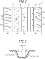
- FIG. 2 illustrates a developed view of the tread surface at an unloaded condition, when the tire of FIG. 1 is mounted to an applicable rim and is applied with a prescribed internal pressure.
- the tread portion 2 has circumferential main grooves 11, 12, 13 extending in the tire circumferential direction, and land portions are partitioned by these circumferential main grooves and tread edges TE1 and TE2.
- the three circumferential main grooves 11, 12 and 13 are formed in order from the sidewall portion 3a side on which the side reinforcement layer 9 is disposed.
- the circumferential main grooves 11 and 13 are formed in a manner such that a contact width W1 of a land portion 14a on a tire widthwise outermost side of the half portion 1a on one side of the tire 1, which is partitioned by the circumferential main groove 11 and the tread edge TE1, is larger than a contact width W2 of a land portion 14b on a tire widthwise outermost side of the half portion 1b on the other side of the tire 1, which is partitioned by the circumferential main groove 13 and the tread edge TE2.
- a central land portion 15a is partitioned by the circumferential main grooves 11 and 12, and a central land portion 15b is partitioned by the circumferential main grooves 12 and 13.
- one circumferential minor groove 16 is formed on the land portion 14a on the tire widthwise outermost side of the half portion 1a on one side.
- sipes 17a, 17b, 17c and 17d of a predetermined pattern are respectively formed on the land portions 14a and 14b on the tire widthwise outermost sides.
- lateral grooves 18a and 18b extending in the tire width direction are respectively formed on the land portions 14a and 14b on the tire widthwise outermost sides.
- FIG. 3 illustrates a tire widthwise cross sectional view of the circumferential main groove of the tread pattern of FIG. 2 .
- the circumferential main groove 11 is formed in a manner such that an angle ⁇ 1 of the groove wall 11a formed on one tire widthwise side of the tire 1 to the tire radial direction is larger than an angle ⁇ 2 of the groove wall 11b formed on the other tire widthwise side of the tire 1 to the tire radial direction.
- the circumferential main groove 12 is formed in a manner such that an angle ⁇ 1 of a groove wall 12a formed on one tire widthwise side of the tire 1 to the tire radial direction is larger than an angle ⁇ 2 of a groove wall 12b formed on the other tire widthwise side of the tire 1 to the tire radial direction; and the circumferential main groove 13 is formed in a manner such that an angle ⁇ 1 of a groove wall 13a formed on one tire widthwise side of the tire 1 to the tire radial direction is larger than an angle ⁇ 2 of a groove wall 13b formed on the other tire widthwise side of the tire 1 to the tire radial direction.
- the effect of the tire according to present embodiment is described in the following. Here, described is the effect when the tire is mounted to a vehicle in a manner such that the aforementioned half portion on one tire widthwise side (the half portion on the side on which the side reinforcement layer 9 is arranged) is on an outer side when mounted to the vehicle.
- the side reinforcement layer 9 which is formed of a treated member formed by coating with rubber organic fiber cords extending parallelly to the ply cords of the carcass ply of the carcass main body 5a of the carcass 5, is arranged (on the tire widthwise outer side of the carcass main body 5a in the present embodiment) only on the sidewall portion 3a of the half portion 1a on the outer side when mounted to the vehicle partitioned by the tire equatorial plain CL; the tire radial inner end 9a of the side reinforcement layer 9 is located on a side inner in the tire radial direction than a tire radial outermost position RO of a rim flange; and the tire radial outermost end 9b of the side reinforcement layer 9 overlaps the belt 6 (the maximum width belt layer 6a) in the tire width direction by 5 mm or more. Therefore, it is possible to improve the resistance to pinch cut of the outer side when mounted to the vehicle without increasing the number of carcass plies of the carcass 5, and thus it is possible
- the tread portion 2 has thereon one or more circumferential main grooves 11, 12 and 13 extending in the tire circumferential direction, and the contact width W1 of the tire widthwise outermost land portion 14a of the half portion 1a on one tire widthwise side is set larger than the contact width W2 of the tire widthwise outermost land portion 14b of the half portion 1a on the other tire widthwise side. Therefore, the variation of conicity due to the asymmetric structure obtained by arranging the side reinforcement layer 9 is counterbalanced by the conicity generated by setting the contact width W1 larger than the contact width W2 and thereby increasing the rigidity of the outer side when mounted to the vehicle.
- the contact width W1 of the tire widthwise outermost land portion 14a on the half portion 1a on one tire widthwise side is preferably 1 to 3 mm larger than the contact width W2 of the tire widthwise outermost land portion 14b on the half portion 1b on the other tire widthwise side. Due to such configuration, the conicity can be optimized more appropriately.
- the thickness of the side rubber of the sidewall portion 3b on the half portion 1b on the other tire widthwise side is preferably larger than the thickness of the side rubber of the sidewall portion 3a on the half portion 1a on one tire widthwise side. According to such configuration, even if the side reinforcement layer 9 is disposed only on the sidewall portion 3a on the half portion 1a on one side, it is possible to prevent the tire widthwise thickness of the sidewall portion 3a on the half portion 1a on one side from being excessively larger than the tire widthwise thickness of the sidewall portion 3b on the half portion 1b on the other side.
- the half portion 1b on the other tire widthwise side is preferably larger than the half portion 1a on one tire widthwise side. According to such configuration, it is possible to improve the rigidity of the inner side when mounted to the vehicle, maintain the durability of the outer side when mounted to the vehicle at a high level, and improve the durability of the inner side when mounted to the vehicle.
- one tire widthwise side ( ⁇ 1) is preferably larger than the other tire widthwise side ( ⁇ 2). In this way, it is possible to ensure the rigidity of the land portions on one tire widthwise side (the outer side when mounted to the vehicle) sandwiching the circumferential grooves, and further optimize the conicity.
- each tire is a pneumatic tire, comprising: a carcass formed of at least one carcass ply, the carcass ply formed of a main body and a folded-up portion, the main body extending toroidally from a tread portion through a pair of sidewall portions to a pair of bead portions, and fixed to bead cores embedded in the bead portions, the folded-up portion extending from the main body and formed by folding up a circumference of the bead cores from a tire widthwise inner side to a tire widthwise outer side; a belt formed of one or more belt layers arranged on a tire radial outer side of a crown portion of the carcass; and bead fillers provided on a tire radial outer side of the bead cores, in which the bead fillers are provided such that at least a part thereof is sandwiched between the carcass main body and the folded-up portion.
- the carcass on the half portion 1a on one side of the tire 1 was formed of one carcass ply, and the side reinforcement layer 9 was inserted therein.
- the carcass on the half portion 1b on the other side of the tire 1 was formed of one carcass ply, and an asymmetrical structure was used as a low-turn-up structure.
- the half portion on one side and the half portion on the other side was set to a symmetrical structure as an envelope structure of one carcass ply.
- the conicity was measured by using the degree of variation of tire radius force (RFV), the degree of variation of lateral force (LFV), and the average value of lateral force (LFD).
- the result was as shown in Table 1.
- the result of pinch cut resistance is represented with index evaluation, with the pinch cut resistance on the outer side of the comparative example tire 3 as 100.
- a larger index shows a better pinch cut resistance.
- the result of uniformity in the table shows the variation of tire conicity with respect to the test result of the uniformity of the comparative example tire 3.
- Example 1 As shown in Table 1, it is understood that as compared to the tires according to comparative examples 1 to 3, in each tire according to examples 1 to 5, even when the durability was high, the variation ratio of uniformity (conicity variation) was low, and the conicity could be optimized. Comparing Example 1 with Example 2, Example 1, in which ⁇ 1> ⁇ 2, had further reduced conicity variation. Comparing Example 2 with Example 3, in Example 2, in which d2>d1, it was possible to maintain a high level of durability of the outer side when mounted to the vehicle, and simultaneously improve the durability of the inner side when mounted to the vehicle. Comparing Example 3 with Example 4, it is understood that in Example 3, in which 3 ⁇ (W1-W2) ⁇ 3, the uniformity variation was smaller. Comparing Example 3 with Example 5, it is understood that in Example 3, in which 3 ⁇ (W1-W2) ⁇ 3, the durability of the inner side when mounted to the vehicle could be improved.
Landscapes
- Engineering & Computer Science (AREA)
- Mechanical Engineering (AREA)
- Tires In General (AREA)
Abstract
Description
- This disclosure relates to a pneumatic tire.
- Regarding pneumatic tires (hereinafter referred to as merely "tires"), especially in the case used on roads which are not sufficiently maintained, the resistance to external damage is an important performance. Recently, the vehicle penetration rate in developing countries, in which there are vast areas with insufficiently maintained roads, and thus requirement to resistance to external damage is increased.
- Such external damage is inclusive of so-called "pinch cut", which refers to cuts of the carcass plies occasionally generated due to the reason that when driving over road segment differences such as curbstones, potholes (small holes generated due to sinkage of a part of a road surface paved with asphalt, etc.) and the like, the tire side portion is raised up and sandwiched between the road protrusion and the rim flange.
- Proposed as a method for ensuring the resistance to pinch cut (pinch cut resistance) is to use carcass plies with an overlapped two-layer structure, and, for example, as described in PTL1, to use a single carcass ply with an envelope structure (a structure such that end portions of the carcass plies extend to the carcass crown portion and the belt layer, and is sandwiched therebetween).
- PTL1:
JP2001-30712A - Recently, in order to maintain the other performances of the tire, and simultaneously save energy in consideration of the earth environment, reduction in tire weight is required in order to reduce the rolling resistance of the tire. In the case where the number of carcass plies of the side portion is increased according to PTL1, although the resistance to pinch cut is improved, there is a problem of increase in the tire weight. Therefore, a method for ensuring the resistance to pinch cut without increasing the number of carcass plies, is desired.
- In view of the aforementioned problem, this disclosure is to provide a pneumatic tire which achieves both weight reduction and durability, and simultaneously enables optimization of conicity.
- The subject of this disclosure is as follows.
- The pneumatic tire of this disclosure includes: a carcass formed of at least one carcass ply, the carcass ply formed of a carcass main body and a carcass folded-up portion, the carcass main body extending toroidally from a tread portion through a pair of sidewall portions to a pair of bead portions, and fixed to bead cores embedded in the bead portions, the carcass folded-up portion extending from the carcass main body and formed by folding up a circumference of the bead cores from a tire widthwise inner side to a tire widthwise outer side; a belt formed of one or more belt layers arranged on a tire radial outer side of a crown portion of the carcass; and bead fillers provided on a tire radial outer side of the bead cores, in which: the bead fillers are provided such that at least a part thereof is sandwiched between the carcass main body and the carcass folded-up portion; a side reinforcement layer is arranged inside the carcass main body, the side reinforcement layer formed of a treated member, the treated member formed by coating with rubber organic fiber cords extending parallelly to ply cords of the carcass ply of the carcass main body, only on a sidewall portion of a half portion on one tire widthwise side partitioned by a tire equatorial plain; at an unloaded condition, when the pneumatic tire is mounted to an applicable rim and is applied with a prescribed internal pressure, a tire radial inner end of the side reinforcement layer is located on a side inner in the tire radial direction than a tire radial outermost position of a rim flange, and a tire radial outer end of the side reinforcement layer overlaps the belt by 5 mm or more in a tire widthwise direction; and the tread portion has one or more circumferential main grooves extending in a tire circumferential direction, and at an unloaded condition, when the pneumatic tire is mounted to an applicable rim and is applied with a prescribed internal pressure, a contact width of a tire widthwise outermost land portion partitioned by the one or more circumferential main grooves and a tread edge on one tire widthwise side is larger than a contact width of a tire widthwise outermost land portion partitioned by the one or more circumferential main grooves and a tread edge on the other tire widthwise side.
- Here, the "applicable rim" is a valid industrial standard for the region in which the tire is produced or used, and refers to a standard rim of an applicable size according to the "JATMA Year Book" in Japan, the "ETRTO STANDARD MANUAL" in Europe, or the "TRA YEAR BOOK" in the United States of America (the "Measuring Rim" in the STANDARDS MANUAL of ETRTO, and the "Design Rim" in the "YEAR BOOK" of TRA).
- Moreover, the "prescribed internal pressure" refers to an internal pressure corresponding to a tire maximum load carrying capacity (maximum air pressure) of a standard of in the aforementioned tire of an applicable size.
- The side reinforcement layer "extending parallelly to the carcass ply" refers to that the dimensional difference at any point in the tire width direction between the carcass ply and the side reinforcement portion at any point of the side reinforcement portion is 50% or less.
- The "contact width" refers to a maximum width in the tire width direction of the contact surface in contact with a flat plate when the tire surface is in contact with the flat plate at a condition when the pneumatic tire is mounted to an applicable rim, applied with a prescribed internal pressure, and applied with a maximum load.
- The "tread edge" refers to a tire widthwise outermost contact position in the aforementioned contact surface of the tread portion.
- The "maximum load" refers to a maximum load (maximum load capability) of a single wheel with an applicable size as described in the aforementioned standards.
- "Overlaps the belt by 5 mm or more in a tire widthwise direction" refers to overlapping by 5 mm or more in the tire width direction a maximum width belt layer with a maximum tire widthwise width among one or more belt layers forming the belt.
- "Extending in a tire circumferential direction" refers to extending toward the tire circumferential direction, and is inclusive of the case extending continuously in a zigzag shape toward the tire circumferential direction, and the case extending continuously in a bended shape toward the tire circumferential direction.
- The "thickness of the side rubber" mentioned below refers to a length of a perpendicular line falling upon the aforementioned organic fiber cord from the sidewall portion surface of the tire maximum width portion as for the aforementioned half portion on one side, and refers to a length of a perpendicular line falling upon a ply cord of the aforementioned carcass ply as for the aforementioned half portion on the other side, at an unloaded condition, when the pneumatic tire is mounted to an applicable rim and is applied with a prescribed internal pressure.
- The "belt end" mentioned below refers to a side on a tire widthwise outer end of the belt layer.
- According to this disclosure, it is possible to provide a pneumatic tire which achieves both weight reduction and durability, and simultaneously enables optimization of conicity.
-
-
FIG. 1 illustrates a schematic cross-sectional view in the tire width direction of the pneumatic tire according to an embodiment of this disclosure; -
FIG. 2 illustrates a developed view of the tread surface of the tire ofFIG. 1 at an unloaded condition, when the tire is mounted to an applicable rim and is applied with a prescribed internal pressure; -
FIG. 3 illustrates a tire widthwise cross sectional view of the circumferential main groove of the tread pattern ofFIG. 2 ; and -
FIG. 4 illustrates the cutting test; - As the results of extensive study, we found that the deformation volume of the wheel when the tire is applied with a load of the inner side when mounted to a vehicle is larger than the outer side when mounted to a vehicle, and thus the inner side when mounted to a vehicle has a better resistance to pinch cut. Based on the aforementioned discovery, we considered that it is possible to obtain the same resistance to pinch cut when using two carcass plies on the outer side when mounted to a vehicle by using one carcass ply on the inner side when mounted to a vehicle.
- Based on such discovery, we further studied an asymmetric structure in which a reinforcement layer is arranged only on the outer side when mounted to a vehicle. As a result, it was discovered that when using an asymmetric structure in which a reinforcement layer formed of a treated member, of which the organic fiber cords are coated with rubber, is arranged in a predetermined region, although it is possible to maintain the pinch cut resistance while reduce the weight, since the tire uses an asymmetric structure, the conicity of the tire is varied. As the results of further extensive study, we found that the variation of conicity due to use of the asymmetric structure in the tire can be counterbalanced with the conicity generated by setting the contact width of the shoulder land portion on the outer side when mounted to a vehicle larger than the contact width of the shoulder land portion on the inner side when mounted to a vehicle. This disclosure is made based on the discovery as described above.
- Hereinafter, an embodiment of this disclosure will be described with reference to the drawings.
-
FIG. 1 illustrates a schematic cross-sectional view in the tire width direction of the pneumatic tire (hereinafter referred to as merely "the tire") according to an embodiment of this disclosure. InFIG. 1 , each member is illustrated schematically for ease of understanding. Therefore, there is the probability that the members as illustrated inFIG. 1 have shape or size different from actual members. Moreover, inFIG. 1 , the tire widthwise cross section of the tire at a standard condition, when the tire is mounted to an applicable rim, applied with a prescribed internal pressure and set to an unloaded condition, is illustrated. - As illustrated in
FIG. 1 , the tire (pneumatic tire) 1 of the present embodiment is formed of atread portion 2 and a pair ofsidewall portions 3, and includes a pair ofbead portions 4, acarcass 5, a belt 6 andbead fillers 7. - The
carcass 5 is formed of at least one carcass ply formed of a carcassmain body 5a and a carcass folded-upportion 5b. The carcassmain body 5a of thecarcass 5 extends toroidally from thetread portion 2 through the pair ofsidewall portions 3 to the pair ofbead portions 4, and is fixed to beadcores 4a embedded in thebead portions 4. The carcass folded-upportion 5b extends from the carcassmain body 5a and folds up the circumference of thebead cores 4a from the tire widthwise inner side to the outer side. The material of the cords of the carcass ply of thecarcass 5 is not specifically limited, and can be, e.g., steel cord, etc. InFIG. 1 , thecarcass 5 is formed of one carcass ply, while thecarcass 5 can be as well formed of two or more carcass plies. - The belt 6 of the tire 1 according to the present embodiment as illustrated in
FIG. 1 is formed of abelt layer 6a arranged on the tire radial outer side of the crown portion of thecarcass 5, and abelt layer 6b having a tire widthwise width smaller than thebelt layer 6a. The twobelt layers belt layer 6a arranged on the tire radial inner side has a tire widthwise width larger than the tire widthwise width of thebelt layer 6b arranged on the tire radial outer side direction. In this disclosure, the belt structure is not limited to the aforementioned example, and the number of belt layers, the widths of each belt layer, the material of the belt cords, etc. can be appropriately varied - The
bead fillers 7 are provided on the tire radial outer sides of thebead cores 4a in a manner such that a part of the tire radial inner side is sandwiched by themain body 5a and the turn-upportion 5b of thecarcass 5. - As illustrated in
FIG. 1 , the tire 1 of the present embodiment includes abelt reinforcement layer 8 on the tire radial outer side of the belt 6. The present embodiment has onebelt reinforcement layer 8, which has a size capable of covering thebelt layers belt reinforcement layer 8 can use cords formed of, e.g., organic fibers, which is not specifically limited, and can be cords formed of organic fibers such as aramid and the like, or hybrid cords of aramid and nylon, etc. The present embodiment has onebelt reinforcement layer 8, but can have two or more as well. Moreover, the tire 1 of this disclosure can include nobelt reinforcement layers 8. - The
belt layer 6a of the present embodiment is arranged in a manner such that regarding the tire widthwise distance from an end of thebelt layer 6a to the tire equatorial plain CL, as compared to the distance d1 of thehalf portion 1a on one side in the tire width direction partitioned by the tire equatorial plain CL of the tire 1, the distance d2 of thehalf portion 1b of the other in the tire width direction partitioned by the tire equatorial plain CL of the tire 1 is larger. - In the present embodiment, among the pair of
sidewall portions 3, aside reinforcement layer 9 is provided only on asidewall portion 3a of thehalf portion 1a on the one side in the tire width direction partitioned by the tire equatorial plain CL of the tire 1. Namely, theside reinforcement layer 9 is not disposed on asidewall portion 3b of thehalf portion 1b on the other side in the tire width direction partitioned by the tire equatorial plain CL of the tire 1. Theside reinforcement layer 9 is formed of a treated member of which the organic fiber cords are coated with rubber, and is arranged within thesidewall portion 3a on one side (in the present embodiment, the tire widthwise outer side of themain body 5a of thecarcass 5 within thesidewall portion 3a) in a manner such that the extension direction of the organic fiber cords is parallel to the extension direction of the ply cords of the carcass ply of the carcassmain body 5a of the carcass 5 (i.e., substantively the same direction as the ply cords). - As illustrated in
FIG. 1 , theside reinforcement layer 9 of the present embodiment is disposed in a manner such that at an unloaded condition (standard condition), when the pneumatic tire 1 is mounted to an applicable rim and is applied with a prescribed internal pressure, a tire radialinner end portion 9a of theside reinforcement layer 9 is located on a side inner in the tire radial than the tire radial outermost position RO of a flange of a rim R. Moreover, at the standard condition, theside reinforcement layer 9 of the present embodiment has a tire widthwise overlapping width D of 5 mm or more of a tire radial outer end portion inclusive of a tire radialouter end 9b of theside reinforcement layer 9 and a maximum width belt layer (in the present embodiment, thebelt layer 6a) having a maximum tire widthwise width among the belt layer forming the belt 6. -
FIG. 2 illustrates a developed view of the tread surface at an unloaded condition, when the tire ofFIG. 1 is mounted to an applicable rim and is applied with a prescribed internal pressure. Thetread portion 2 has circumferentialmain grooves main grooves sidewall portion 3a side on which theside reinforcement layer 9 is disposed. In the present embodiment, the circumferentialmain grooves land portion 14a on a tire widthwise outermost side of thehalf portion 1a on one side of the tire 1, which is partitioned by the circumferentialmain groove 11 and the tread edge TE1, is larger than a contact width W2 of aland portion 14b on a tire widthwise outermost side of thehalf portion 1b on the other side of the tire 1, which is partitioned by the circumferentialmain groove 13 and the tread edge TE2. Further, in the present embodiment, acentral land portion 15a is partitioned by the circumferentialmain grooves central land portion 15b is partitioned by the circumferentialmain grooves - As illustrated in
FIG. 1 , on theland portion 14a on the tire widthwise outermost side of thehalf portion 1a on one side, one circumferentialminor groove 16 is formed. Moreover, on theland portions central land portions sipes land portions lateral grooves -
FIG. 3 illustrates a tire widthwise cross sectional view of the circumferential main groove of the tread pattern ofFIG. 2 . As illustrated inFIG. 3 , in the present embodiment, at an unloaded condition, when the tire 1 is mounted to the rim R and is applied with a prescribed internal pressure, the circumferentialmain groove 11 is formed in a manner such that an angle θ1 of thegroove wall 11a formed on one tire widthwise side of the tire 1 to the tire radial direction is larger than an angle θ2 of thegroove wall 11b formed on the other tire widthwise side of the tire 1 to the tire radial direction. Similarly, the circumferentialmain groove 12 is formed in a manner such that an angle θ1 of agroove wall 12a formed on one tire widthwise side of the tire 1 to the tire radial direction is larger than an angle θ2 of agroove wall 12b formed on the other tire widthwise side of the tire 1 to the tire radial direction; and the circumferentialmain groove 13 is formed in a manner such that an angle θ1 of agroove wall 13a formed on one tire widthwise side of the tire 1 to the tire radial direction is larger than an angle θ2 of agroove wall 13b formed on the other tire widthwise side of the tire 1 to the tire radial direction. - The effect of the tire according to present embodiment is described in the following. Here, described is the effect when the tire is mounted to a vehicle in a manner such that the aforementioned half portion on one tire widthwise side (the half portion on the side on which the
side reinforcement layer 9 is arranged) is on an outer side when mounted to the vehicle. According to the tire of the present embodiment, theside reinforcement layer 9, which is formed of a treated member formed by coating with rubber organic fiber cords extending parallelly to the ply cords of the carcass ply of the carcassmain body 5a of thecarcass 5, is arranged (on the tire widthwise outer side of the carcassmain body 5a in the present embodiment) only on thesidewall portion 3a of thehalf portion 1a on the outer side when mounted to the vehicle partitioned by the tire equatorial plain CL; the tire radialinner end 9a of theside reinforcement layer 9 is located on a side inner in the tire radial direction than a tire radial outermost position RO of a rim flange; and the tire radialoutermost end 9b of theside reinforcement layer 9 overlaps the belt 6 (the maximumwidth belt layer 6a) in the tire width direction by 5 mm or more. Therefore, it is possible to improve the resistance to pinch cut of the outer side when mounted to the vehicle without increasing the number of carcass plies of thecarcass 5, and thus it is possible to achieve both pinch cut resistance and weight reduction. - Moreover, according to the tire of the present embodiment, the
tread portion 2 has thereon one or more circumferentialmain grooves outermost land portion 14a of thehalf portion 1a on one tire widthwise side is set larger than the contact width W2 of the tire widthwiseoutermost land portion 14b of thehalf portion 1a on the other tire widthwise side. Therefore, the variation of conicity due to the asymmetric structure obtained by arranging theside reinforcement layer 9 is counterbalanced by the conicity generated by setting the contact width W1 larger than the contact width W2 and thereby increasing the rigidity of the outer side when mounted to the vehicle. - As mentioned above, according to the tire of the present embodiment, it is possible to achieve both weight reduction and durability, and simultaneously optimize the conicity.
- At an unloaded condition, when the tire 1 is mounted to an applicable rim and is applied with a prescribed internal pressure, in the case where the tire radial
inner end 9a of theside reinforcement layer 9 is not located on a side inner in the tire radial direction than the tire radial outermost position RO of the rim flange, and/or the tire widthwise overlap of the tire radialouter end 9b of theside reinforcement layer 9 and the belt 6 (the maximumwidth belt layer 6a) is less than 5mm, there is the probability that reinforcement to thesidewall portion 3a on one side is insufficient. - Here, in this disclosure, the contact width W1 of the tire widthwise
outermost land portion 14a on thehalf portion 1a on one tire widthwise side is preferably 1 to 3 mm larger than the contact width W2 of the tire widthwiseoutermost land portion 14b on thehalf portion 1b on the other tire widthwise side. Due to such configuration, the conicity can be optimized more appropriately. - In the pneumatic tire 1 of this disclosure, the thickness of the side rubber of the
sidewall portion 3b on thehalf portion 1b on the other tire widthwise side is preferably larger than the thickness of the side rubber of thesidewall portion 3a on thehalf portion 1a on one tire widthwise side. According to such configuration, even if theside reinforcement layer 9 is disposed only on thesidewall portion 3a on thehalf portion 1a on one side, it is possible to prevent the tire widthwise thickness of thesidewall portion 3a on thehalf portion 1a on one side from being excessively larger than the tire widthwise thickness of thesidewall portion 3b on thehalf portion 1b on the other side. - In the pneumatic tire of this disclosure, regarding the tire widthwise distance from an end of the belt (in the present embodiment, the maximum
width belt layer 6a) to the tire equatorial plain CL, thehalf portion 1b on the other tire widthwise side is preferably larger than thehalf portion 1a on one tire widthwise side. According to such configuration, it is possible to improve the rigidity of the inner side when mounted to the vehicle, maintain the durability of the outer side when mounted to the vehicle at a high level, and improve the durability of the inner side when mounted to the vehicle. - In the pneumatic tire of this disclosure, at an unloaded condition, when the tire is mounted to an applicable rim and is applied with a prescribed internal pressure, regarding the angle of the groove walls of the circumferential
main grooves - Hereinafter, examples for this disclosure are described, while this disclosure is not limited to these examples.
- In order to certify the effect of this disclosure, the tires of Examples 1 to 5 and Comparative Examples 1 to 3 were produced experimentally. The dimensions of each tire are as shown in the following Table 1. The tire size of each is 215/645R17. Further, with respect to each tire, tests for evaluating pinch cut resistance and uniformity were performed. Here, as illustrated in
FIG. 1 , each tire is a pneumatic tire, comprising: a carcass formed of at least one carcass ply, the carcass ply formed of a main body and a folded-up portion, the main body extending toroidally from a tread portion through a pair of sidewall portions to a pair of bead portions, and fixed to bead cores embedded in the bead portions, the folded-up portion extending from the main body and formed by folding up a circumference of the bead cores from a tire widthwise inner side to a tire widthwise outer side; a belt formed of one or more belt layers arranged on a tire radial outer side of a crown portion of the carcass; and bead fillers provided on a tire radial outer side of the bead cores, in which the bead fillers are provided such that at least a part thereof is sandwiched between the carcass main body and the folded-up portion. - In the tires of Examples 1 to 5 and Comparative Examples 1 to 2, the carcass on the
half portion 1a on one side of the tire 1 was formed of one carcass ply, and theside reinforcement layer 9 was inserted therein. The carcass on thehalf portion 1b on the other side of the tire 1 was formed of one carcass ply, and an asymmetrical structure was used as a low-turn-up structure. In the tire of Comparative Example 3, the half portion on one side and the half portion on the other side was set to a symmetrical structure as an envelope structure of one carcass ply. - At a stationary state after the tires of the aforementioned examples and comparative examples were mounted to a rim (size: 7J), applied with an internal pressure of 230kPa, an mounted to a vehicle in a manner such that the
half portion 1a on one side is on the outer side of the vehicle, a tapered metal piece M as illustrated inFIG. 4 was slowly pushed into the tread surface of the tire, and the value obtained by integrating the displacement amount of the metal piece M and the load applied to the metal piece when damage or failure occurs to the ply was calculated as the pinch cut resistance. The test was performed by pushing the metal piece onto the tread edge on the vehicle inner side from the vehicle outer side of the tire. - After the tires of the aforementioned examples and comparative examples were mounted to a rim (size: 7J), and applied with an internal pressure of 196 kPa, at a state where the tire is rotated at 60 r/min and applied with a load of 85% of a maximum load, the conicity was measured by using the degree of variation of tire radius force (RFV), the degree of variation of lateral force (LFV), and the average value of lateral force (LFD).
- In the case where an average value of a waveform of a side force to the inner side direction when mounted to the vehicle per rotation of the tire (the side force applied to the drum) is LFD, the conicity is defined as follows.

- The result was as shown in Table 1. In the table, the result of pinch cut resistance is represented with index evaluation, with the pinch cut resistance on the outer side of the
comparative example tire 3 as 100. Here, a larger index shows a better pinch cut resistance. The result of uniformity in the table shows the variation of tire conicity with respect to the test result of the uniformity of thecomparative example tire 3.[Table 1] Example 1 Example 2 Example 3 Example 4 Example 5 Comparative Example 1 Comparative Example 2 Comparative Example 3 Side reinforcement layer 9Overlapping width D (mm) 10 10 10 10 10 10 3 - Land portion 14aContact width W1 (mm) 30 30 30 28.5 32 28 28 28 Land portion 14bContact width W2 (mm) 28 28 28 28 28 28 28 28 W1-W2 (mm) 2 2 2 0.5 4 0 0 0 Inclined belt layer 3ad1 (mm) 87 87 88 88 88 87 87 87 d2 (mm) 88 88 87 87 87 87 87 87 Groove inclination angle of grooves θ1 12 8 8 8 8 8 8 8 θ2 8 12 12 12 12 8 8 8 Pinch out resistance on vehicle outer side 110 110 112 110 110 110 105 100 Pinch out resistance on vehicle inner side 102 102 101 100 100 100 100 100 Uniformity 0 -16 -16 -25 16 -40 -15 0 - As shown in Table 1, it is understood that as compared to the tires according to comparative examples 1 to 3, in each tire according to examples 1 to 5, even when the durability was high, the variation ratio of uniformity (conicity variation) was low, and the conicity could be optimized. Comparing Example 1 with Example 2, Example 1, in which θ1>θ2, had further reduced conicity variation. Comparing Example 2 with Example 3, in Example 2, in which d2>d1, it was possible to maintain a high level of durability of the outer side when mounted to the vehicle, and simultaneously improve the durability of the inner side when mounted to the vehicle. Comparing Example 3 with Example 4, it is understood that in Example 3, in which 3≤(W1-W2)≤3, the uniformity variation was smaller. Comparing Example 3 with Example 5, it is understood that in Example 3, in which 3≤(W1-W2)≤3, the durability of the inner side when mounted to the vehicle could be improved.
-
- 1:
- tire (pneumatic tire)
- 1a:
- half portion
- 1b:
- half portion
- 2:
- tread portion
- 3:
- sidewall portion
- 4:
- bead portion
- 4a:
- bead core
- 5:
- carcass
- 5a:
- carcass main body
- 5b:
- carcass folded-up portion
- 6:
- belt
- 6a, 6b:
- belt layer
- 7:
- bead filler
- 8:
- belt reinforcement layer
- 9:
- side reinforcement layer
- 9a:
- tire radial inner end
- 9b:
- tire radial outer end
- 11:
- circumferential main groove
- 12:
- circumferential main groove
- 13:
- circumferential main groove
- 14a:
- outermost land portion
- 14b:
- outermost land portion
- 15a:
- central land portion
- 15b:
- central land portion
- 16:
- minor groove
- 17a:
- sipe
- 17b:
- sipe
- 17c:
- sipe
- 17d:
- sipe
- 18a:
- lateral groove
- 18b:
- lateral groove
- CL:
- tire equatorial plain
- d1:
- distance
- d2:
- distance
- D:
- width
- M:
- metal piece
- R:
- rim
- RO:
- tire radial outermost position
- TE1:
- tread edge
- TE2:
- tread edge
- W1:
- contact width
- W2:
- contact width
Claims (5)
- A pneumatic tire, comprising: a carcass formed of at least one carcass ply, the carcass ply formed of a carcass main body and a carcass folded-up portion, the carcass main body extending toroidally from a tread portion through a pair of sidewall portions to a pair of bead portions, and fixed to bead cores embedded in the bead portions, the carcass folded-up portion extending from the carcass main body and formed by folding up a circumference of the bead cores from a tire widthwise inner side to a tire widthwise outer side; a belt formed of one or more belt layers arranged on a tire radial outer side of a crown portion of the carcass; and bead fillers provided on a tire radial outer side of the bead cores, wherein:the bead fillers are provided such that at least a part thereof is sandwiched between the carcass main body and the carcass folded-up portion,a side reinforcement layer is arranged inside the carcass main body, the side reinforcement layer formed of a treated member, the treated member formed by coating with rubber organic fiber cords extending parallelly to ply cords of the carcass ply of the carcass main body, only on a sidewall portion of a half portion on one tire widthwise side partitioned by a tire equatorial plain,at an unloaded condition, when the pneumatic tire is mounted to an applicable rim and is applied with a prescribed internal pressure, a tire radial inner end of the side reinforcement layer is located on a side inner in the tire radial direction than a tire radial outermost position of a rim flange, and a tire radial outer end of the side reinforcement layer overlaps the belt by 5 mm or more in a tire widthwise direction, andthe tread portion has one or more circumferential main grooves extending in a tire circumferential direction, and at an unloaded condition, when the pneumatic tire is mounted to an applicable rim and is applied with a prescribed internal pressure, a contact width of a tire widthwise outermost land portion partitioned by the one or more circumferential main grooves and a tread edge on one tire widthwise side is larger than a contact width of a tire widthwise outermost land portion partitioned by the one or more circumferential main grooves and a tread edge on the other tire widthwise side.
- The pneumatic tire according to claim 1, wherein: a contact width of the tire widthwise outermost land portion on the half portion on one tire widthwise side is 1 to 3 mm larger than a contact width of the tire widthwise outermost land portion the half portion on the other tire widthwise side.
- The pneumatic tire according to claim 1 or 2, wherein: a thickness of a side rubber of the sidewall portion on the half portion on the other tire widthwise side is larger than a thickness of a side rubber of the sidewall portion on the half portion on one tire widthwise side.
- The pneumatic tire according to any one of claims 1 to 3, wherein: at an unloaded condition, when the pneumatic tire is mounted to an applicable rim and is applied with a prescribed internal pressure, a tire widthwise distance from an end of the belt to the tire equatorial plain of the half portion on the other tire widthwise side is larger than the half portion on one tire widthwise side.
- The pneumatic tire according to any one of claims 1 to 4, wherein: at an unloaded condition, when the pneumatic tire is mounted to an applicable rim and is applied with a prescribed internal pressure, an angle of groove walls of the circumferential main grooves to the tire radial direction of one tire widthwise side is larger than the other tire widthwise side.
Applications Claiming Priority (2)
| Application Number | Priority Date | Filing Date | Title |
|---|---|---|---|
| JP2014153167A JP6548368B2 (en) | 2014-07-28 | 2014-07-28 | Pneumatic tire |
| PCT/JP2015/003778 WO2016017149A1 (en) | 2014-07-28 | 2015-07-28 | Pneumatic tyre |
Publications (3)
| Publication Number | Publication Date |
|---|---|
| EP3176009A1 true EP3176009A1 (en) | 2017-06-07 |
| EP3176009A4 EP3176009A4 (en) | 2017-08-23 |
| EP3176009B1 EP3176009B1 (en) | 2018-11-21 |
Family
ID=55217065
Family Applications (1)
| Application Number | Title | Priority Date | Filing Date |
|---|---|---|---|
| EP15827636.0A Not-in-force EP3176009B1 (en) | 2014-07-28 | 2015-07-28 | Pneumatic tyre |
Country Status (5)
| Country | Link |
|---|---|
| US (1) | US10913313B2 (en) |
| EP (1) | EP3176009B1 (en) |
| JP (1) | JP6548368B2 (en) |
| CN (1) | CN106536231B (en) |
| WO (1) | WO2016017149A1 (en) |
Cited By (1)
| Publication number | Priority date | Publication date | Assignee | Title |
|---|---|---|---|---|
| CN109421443A (en) * | 2017-08-30 | 2019-03-05 | 住友橡胶工业株式会社 | Pneumatic belt tire |
Families Citing this family (8)
| Publication number | Priority date | Publication date | Assignee | Title |
|---|---|---|---|---|
| JP6135719B2 (en) * | 2015-08-06 | 2017-05-31 | 横浜ゴム株式会社 | Pneumatic tire |
| JP6662259B2 (en) * | 2016-09-26 | 2020-03-11 | 横浜ゴム株式会社 | Pneumatic tire |
| JP6465192B1 (en) * | 2017-11-20 | 2019-02-06 | 横浜ゴム株式会社 | Pneumatic tire |
| JP6521115B1 (en) * | 2018-01-30 | 2019-05-29 | 横浜ゴム株式会社 | Pneumatic tire |
| WO2019151333A1 (en) * | 2018-01-30 | 2019-08-08 | 横浜ゴム株式会社 | Pneumatic tire |
| JP7348828B2 (en) * | 2019-12-13 | 2023-09-21 | Toyo Tire株式会社 | pneumatic tires |
| JP7639368B2 (en) * | 2021-01-28 | 2025-03-05 | 住友ゴム工業株式会社 | tire |
| JPWO2024262194A1 (en) * | 2023-06-23 | 2024-12-26 |
Family Cites Families (25)
| Publication number | Priority date | Publication date | Assignee | Title |
|---|---|---|---|---|
| FR1444222A (en) * | 1965-05-20 | 1966-07-01 | Pneumatiques, Caoutchouc Manufacture Et Plastiques Kleber Colombes | Reinforced crown tire |
| NL134150C (en) * | 1966-07-11 | |||
| JPS5940903A (en) * | 1982-08-31 | 1984-03-06 | Yokohama Rubber Co Ltd:The | Radial tire |
| JPS61253205A (en) | 1985-05-01 | 1986-11-11 | Bridgestone Corp | Non-symmetrical pneumatic tire for racing |
| JPS638003A (en) * | 1986-06-30 | 1988-01-13 | Yokohama Rubber Co Ltd:The | Pneumatic tyre |
| JPH06143945A (en) | 1992-10-30 | 1994-05-24 | Sumitomo Rubber Ind Ltd | Pneumatic tire |
| JPH06199113A (en) | 1992-12-28 | 1994-07-19 | Sumitomo Rubber Ind Ltd | Pneumatic tire |
| JP2001030712A (en) | 1999-07-15 | 2001-02-06 | Bridgestone Corp | Pneumatic tire |
| JP2001121922A (en) * | 1999-10-25 | 2001-05-08 | Bridgestone Corp | Pneumatic tire |
| JP2003231405A (en) * | 2002-02-12 | 2003-08-19 | Yokohama Rubber Co Ltd:The | Pneumatic tire |
| JP4457388B2 (en) | 2005-02-08 | 2010-04-28 | 東洋ゴム工業株式会社 | Run flat tire |
| DE102005025236A1 (en) * | 2005-06-01 | 2006-12-07 | Continental Aktiengesellschaft | vehicle tires |
| EP1893420B1 (en) * | 2005-06-06 | 2011-12-21 | Michelin Recherche et Technique S.A. | Tire with sidewall reinforcement |
| JP4502333B2 (en) | 2006-06-27 | 2010-07-14 | 東洋ゴム工業株式会社 | Run flat tire |
| US7669625B2 (en) | 2006-11-22 | 2010-03-02 | The Goodyear Tire & Rubber Company | Asymmetrical pneumatic tire |
| JP2008155866A (en) | 2006-12-26 | 2008-07-10 | Bridgestone Corp | Pneumatic tire and vehicle with the same |
| JP2008279877A (en) | 2007-05-10 | 2008-11-20 | Yokohama Rubber Co Ltd:The | Pneumatic radial tire |
| JP5251178B2 (en) * | 2008-03-11 | 2013-07-31 | 横浜ゴム株式会社 | Pneumatic tire |
| JP5298668B2 (en) | 2008-07-02 | 2013-09-25 | 横浜ゴム株式会社 | Pneumatic tire |
| JP5326669B2 (en) | 2009-03-05 | 2013-10-30 | 横浜ゴム株式会社 | Pneumatic tire |
| CN102348563B (en) * | 2009-03-11 | 2015-06-24 | 株式会社普利司通 | Run-flat tire |
| JP2010247698A (en) | 2009-04-16 | 2010-11-04 | Bridgestone Corp | Run-flat tire |
| JP2013014227A (en) * | 2011-07-04 | 2013-01-24 | Bridgestone Corp | Pneumatic radial tire |
| JP5503622B2 (en) * | 2011-11-08 | 2014-05-28 | 住友ゴム工業株式会社 | Pneumatic tire |
| JP6055187B2 (en) | 2012-02-21 | 2016-12-27 | 株式会社ブリヂストン | Pneumatic tire |
-
2014
- 2014-07-28 JP JP2014153167A patent/JP6548368B2/en not_active Expired - Fee Related
-
2015
- 2015-07-28 WO PCT/JP2015/003778 patent/WO2016017149A1/en not_active Ceased
- 2015-07-28 EP EP15827636.0A patent/EP3176009B1/en not_active Not-in-force
- 2015-07-28 US US15/327,261 patent/US10913313B2/en not_active Expired - Fee Related
- 2015-07-28 CN CN201580040431.3A patent/CN106536231B/en not_active Expired - Fee Related
Cited By (2)
| Publication number | Priority date | Publication date | Assignee | Title |
|---|---|---|---|---|
| CN109421443A (en) * | 2017-08-30 | 2019-03-05 | 住友橡胶工业株式会社 | Pneumatic belt tire |
| EP3450210A1 (en) * | 2017-08-30 | 2019-03-06 | Sumitomo Rubber Industries, Ltd. | Pneumatic radial tire |
Also Published As
| Publication number | Publication date |
|---|---|
| WO2016017149A1 (en) | 2016-02-04 |
| US10913313B2 (en) | 2021-02-09 |
| CN106536231B (en) | 2018-11-30 |
| EP3176009A4 (en) | 2017-08-23 |
| CN106536231A (en) | 2017-03-22 |
| JP2016030490A (en) | 2016-03-07 |
| US20170157985A1 (en) | 2017-06-08 |
| JP6548368B2 (en) | 2019-07-24 |
| EP3176009B1 (en) | 2018-11-21 |
Similar Documents
| Publication | Publication Date | Title |
|---|---|---|
| EP3176009B1 (en) | Pneumatic tyre | |
| EP3202596B1 (en) | Run-flat tire | |
| EP2724871B1 (en) | Passenger vehicle | |
| EP3213930B1 (en) | Pneumatic tire | |
| JP5915505B2 (en) | Pneumatic tire | |
| US9415637B2 (en) | Pneumatic tire | |
| EP3064374B1 (en) | Tire | |
| EP2962874B1 (en) | Pneumatic radial tire for passenger vehicle | |
| EP2979900B1 (en) | Heavy load pneumatic tire | |
| US11548323B2 (en) | Pneumatic tire | |
| EP3202598B1 (en) | Run-flat tire | |
| RU2609910C1 (en) | Heavy duty tire | |
| US20210370723A1 (en) | Pneumatic Tire | |
| US10569602B2 (en) | Heavy load tire with specified belt layers | |
| EP3213929B1 (en) | Pneumatic tire for passenger cars | |
| EP1712377A1 (en) | Pneumatic tire | |
| EP3064377B1 (en) | Tire | |
| US12508848B2 (en) | Pneumatic tire | |
| EP3330102B1 (en) | Pneumatic tire for motorcycles | |
| EP3202597B1 (en) | Run-flat tire | |
| EP3181375B1 (en) | Pneumatic tire | |
| US11633988B2 (en) | Pneumatic tire |
Legal Events
| Date | Code | Title | Description |
|---|---|---|---|
| STAA | Information on the status of an ep patent application or granted ep patent |
Free format text: STATUS: THE INTERNATIONAL PUBLICATION HAS BEEN MADE |
|
| 17P | Request for examination filed |
Effective date: 20170119 |
|
| AK | Designated contracting states |
Kind code of ref document: A1 Designated state(s): AL AT BE BG CH CY CZ DE DK EE ES FI FR GB GR HR HU IE IS IT LI LT LU LV MC MK MT NL NO PL PT RO RS SE SI SK SM TR |
|
| AX | Request for extension of the european patent |
Extension state: BA ME |
|
| PUAI | Public reference made under article 153(3) epc to a published international application that has entered the european phase |
Free format text: ORIGINAL CODE: 0009012 |
|
| STAA | Information on the status of an ep patent application or granted ep patent |
Free format text: STATUS: REQUEST FOR EXAMINATION WAS MADE |
|
| A4 | Supplementary search report drawn up and despatched |
Effective date: 20170720 |
|
| RIC1 | Information provided on ipc code assigned before grant |
Ipc: B29D 30/48 20060101ALI20170714BHEP Ipc: B29D 30/38 20060101ALI20170714BHEP Ipc: B60C 11/03 20060101ALI20170714BHEP Ipc: B60C 11/13 20060101ALI20170714BHEP Ipc: B29D 30/72 20060101ALI20170714BHEP Ipc: B60C 15/02 20060101ALI20170714BHEP Ipc: B60C 15/06 20060101ALI20170714BHEP Ipc: B60C 3/06 20060101ALI20170714BHEP Ipc: B60C 13/00 20060101AFI20170714BHEP Ipc: B60C 9/30 20060101ALI20170714BHEP Ipc: B29D 30/32 20060101ALI20170714BHEP Ipc: B60C 15/04 20060101ALI20170714BHEP Ipc: B60C 19/00 20060101ALI20170714BHEP |
|
| DAV | Request for validation of the european patent (deleted) | ||
| DAX | Request for extension of the european patent (deleted) | ||
| RIC1 | Information provided on ipc code assigned before grant |
Ipc: B60C 13/00 20060101AFI20180423BHEP Ipc: B60C 9/30 20060101ALI20180423BHEP Ipc: B60C 15/04 20060101ALI20180423BHEP Ipc: B60C 15/02 20060101ALI20180423BHEP Ipc: B29D 30/32 20060101ALI20180423BHEP Ipc: B60C 3/06 20060101ALI20180423BHEP Ipc: B60C 15/06 20060101ALI20180423BHEP Ipc: B60C 11/03 20060101ALI20180423BHEP Ipc: B29D 30/38 20060101ALI20180423BHEP Ipc: B29D 30/48 20060101ALI20180423BHEP Ipc: B60C 19/00 20060101ALI20180423BHEP Ipc: B60C 11/13 20060101ALI20180423BHEP Ipc: B29D 30/72 20060101ALI20180423BHEP |
|
| GRAP | Despatch of communication of intention to grant a patent |
Free format text: ORIGINAL CODE: EPIDOSNIGR1 |
|
| STAA | Information on the status of an ep patent application or granted ep patent |
Free format text: STATUS: GRANT OF PATENT IS INTENDED |
|
| INTG | Intention to grant announced |
Effective date: 20180605 |
|
| GRAS | Grant fee paid |
Free format text: ORIGINAL CODE: EPIDOSNIGR3 |
|
| GRAA | (expected) grant |
Free format text: ORIGINAL CODE: 0009210 |
|
| STAA | Information on the status of an ep patent application or granted ep patent |
Free format text: STATUS: THE PATENT HAS BEEN GRANTED |
|
| AK | Designated contracting states |
Kind code of ref document: B1 Designated state(s): AL AT BE BG CH CY CZ DE DK EE ES FI FR GB GR HR HU IE IS IT LI LT LU LV MC MK MT NL NO PL PT RO RS SE SI SK SM TR |
|
| REG | Reference to a national code |
Ref country code: CH Ref legal event code: EP |
|
| REG | Reference to a national code |
Ref country code: IE Ref legal event code: FG4D |
|
| REG | Reference to a national code |
Ref country code: DE Ref legal event code: R096 Ref document number: 602015020202 Country of ref document: DE |
|
| REG | Reference to a national code |
Ref country code: AT Ref legal event code: REF Ref document number: 1067112 Country of ref document: AT Kind code of ref document: T Effective date: 20181215 |
|
| REG | Reference to a national code |
Ref country code: NL Ref legal event code: MP Effective date: 20181121 |
|
| REG | Reference to a national code |
Ref country code: AT Ref legal event code: MK05 Ref document number: 1067112 Country of ref document: AT Kind code of ref document: T Effective date: 20181121 |
|
| PG25 | Lapsed in a contracting state [announced via postgrant information from national office to epo] |
Ref country code: FI Free format text: LAPSE BECAUSE OF FAILURE TO SUBMIT A TRANSLATION OF THE DESCRIPTION OR TO PAY THE FEE WITHIN THE PRESCRIBED TIME-LIMIT Effective date: 20181121 Ref country code: LV Free format text: LAPSE BECAUSE OF FAILURE TO SUBMIT A TRANSLATION OF THE DESCRIPTION OR TO PAY THE FEE WITHIN THE PRESCRIBED TIME-LIMIT Effective date: 20181121 Ref country code: LT Free format text: LAPSE BECAUSE OF FAILURE TO SUBMIT A TRANSLATION OF THE DESCRIPTION OR TO PAY THE FEE WITHIN THE PRESCRIBED TIME-LIMIT Effective date: 20181121 Ref country code: NO Free format text: LAPSE BECAUSE OF FAILURE TO SUBMIT A TRANSLATION OF THE DESCRIPTION OR TO PAY THE FEE WITHIN THE PRESCRIBED TIME-LIMIT Effective date: 20190221 Ref country code: HR Free format text: LAPSE BECAUSE OF FAILURE TO SUBMIT A TRANSLATION OF THE DESCRIPTION OR TO PAY THE FEE WITHIN THE PRESCRIBED TIME-LIMIT Effective date: 20181121 Ref country code: AT Free format text: LAPSE BECAUSE OF FAILURE TO SUBMIT A TRANSLATION OF THE DESCRIPTION OR TO PAY THE FEE WITHIN THE PRESCRIBED TIME-LIMIT Effective date: 20181121 Ref country code: BG Free format text: LAPSE BECAUSE OF FAILURE TO SUBMIT A TRANSLATION OF THE DESCRIPTION OR TO PAY THE FEE WITHIN THE PRESCRIBED TIME-LIMIT Effective date: 20190221 Ref country code: IS Free format text: LAPSE BECAUSE OF FAILURE TO SUBMIT A TRANSLATION OF THE DESCRIPTION OR TO PAY THE FEE WITHIN THE PRESCRIBED TIME-LIMIT Effective date: 20190321 |
|
| PG25 | Lapsed in a contracting state [announced via postgrant information from national office to epo] |
Ref country code: GR Free format text: LAPSE BECAUSE OF FAILURE TO SUBMIT A TRANSLATION OF THE DESCRIPTION OR TO PAY THE FEE WITHIN THE PRESCRIBED TIME-LIMIT Effective date: 20190222 Ref country code: NL Free format text: LAPSE BECAUSE OF FAILURE TO SUBMIT A TRANSLATION OF THE DESCRIPTION OR TO PAY THE FEE WITHIN THE PRESCRIBED TIME-LIMIT Effective date: 20181121 Ref country code: PT Free format text: LAPSE BECAUSE OF FAILURE TO SUBMIT A TRANSLATION OF THE DESCRIPTION OR TO PAY THE FEE WITHIN THE PRESCRIBED TIME-LIMIT Effective date: 20190321 Ref country code: RS Free format text: LAPSE BECAUSE OF FAILURE TO SUBMIT A TRANSLATION OF THE DESCRIPTION OR TO PAY THE FEE WITHIN THE PRESCRIBED TIME-LIMIT Effective date: 20181121 Ref country code: AL Free format text: LAPSE BECAUSE OF FAILURE TO SUBMIT A TRANSLATION OF THE DESCRIPTION OR TO PAY THE FEE WITHIN THE PRESCRIBED TIME-LIMIT Effective date: 20181121 Ref country code: SE Free format text: LAPSE BECAUSE OF FAILURE TO SUBMIT A TRANSLATION OF THE DESCRIPTION OR TO PAY THE FEE WITHIN THE PRESCRIBED TIME-LIMIT Effective date: 20181121 |
|
| PG25 | Lapsed in a contracting state [announced via postgrant information from national office to epo] |
Ref country code: IT Free format text: LAPSE BECAUSE OF FAILURE TO SUBMIT A TRANSLATION OF THE DESCRIPTION OR TO PAY THE FEE WITHIN THE PRESCRIBED TIME-LIMIT Effective date: 20181121 Ref country code: ES Free format text: LAPSE BECAUSE OF FAILURE TO SUBMIT A TRANSLATION OF THE DESCRIPTION OR TO PAY THE FEE WITHIN THE PRESCRIBED TIME-LIMIT Effective date: 20181121 Ref country code: CZ Free format text: LAPSE BECAUSE OF FAILURE TO SUBMIT A TRANSLATION OF THE DESCRIPTION OR TO PAY THE FEE WITHIN THE PRESCRIBED TIME-LIMIT Effective date: 20181121 Ref country code: DK Free format text: LAPSE BECAUSE OF FAILURE TO SUBMIT A TRANSLATION OF THE DESCRIPTION OR TO PAY THE FEE WITHIN THE PRESCRIBED TIME-LIMIT Effective date: 20181121 Ref country code: PL Free format text: LAPSE BECAUSE OF FAILURE TO SUBMIT A TRANSLATION OF THE DESCRIPTION OR TO PAY THE FEE WITHIN THE PRESCRIBED TIME-LIMIT Effective date: 20181121 |
|
| REG | Reference to a national code |
Ref country code: DE Ref legal event code: R097 Ref document number: 602015020202 Country of ref document: DE |
|
| PG25 | Lapsed in a contracting state [announced via postgrant information from national office to epo] |
Ref country code: EE Free format text: LAPSE BECAUSE OF FAILURE TO SUBMIT A TRANSLATION OF THE DESCRIPTION OR TO PAY THE FEE WITHIN THE PRESCRIBED TIME-LIMIT Effective date: 20181121 Ref country code: SM Free format text: LAPSE BECAUSE OF FAILURE TO SUBMIT A TRANSLATION OF THE DESCRIPTION OR TO PAY THE FEE WITHIN THE PRESCRIBED TIME-LIMIT Effective date: 20181121 Ref country code: SK Free format text: LAPSE BECAUSE OF FAILURE TO SUBMIT A TRANSLATION OF THE DESCRIPTION OR TO PAY THE FEE WITHIN THE PRESCRIBED TIME-LIMIT Effective date: 20181121 Ref country code: RO Free format text: LAPSE BECAUSE OF FAILURE TO SUBMIT A TRANSLATION OF THE DESCRIPTION OR TO PAY THE FEE WITHIN THE PRESCRIBED TIME-LIMIT Effective date: 20181121 |
|
| PLBE | No opposition filed within time limit |
Free format text: ORIGINAL CODE: 0009261 |
|
| STAA | Information on the status of an ep patent application or granted ep patent |
Free format text: STATUS: NO OPPOSITION FILED WITHIN TIME LIMIT |
|
| 26N | No opposition filed |
Effective date: 20190822 |
|
| PG25 | Lapsed in a contracting state [announced via postgrant information from national office to epo] |
Ref country code: SI Free format text: LAPSE BECAUSE OF FAILURE TO SUBMIT A TRANSLATION OF THE DESCRIPTION OR TO PAY THE FEE WITHIN THE PRESCRIBED TIME-LIMIT Effective date: 20181121 |
|
| PG25 | Lapsed in a contracting state [announced via postgrant information from national office to epo] |
Ref country code: MC Free format text: LAPSE BECAUSE OF FAILURE TO SUBMIT A TRANSLATION OF THE DESCRIPTION OR TO PAY THE FEE WITHIN THE PRESCRIBED TIME-LIMIT Effective date: 20181121 |
|
| REG | Reference to a national code |
Ref country code: CH Ref legal event code: PL |
|
| GBPC | Gb: european patent ceased through non-payment of renewal fee |
Effective date: 20190728 |
|
| PG25 | Lapsed in a contracting state [announced via postgrant information from national office to epo] |
Ref country code: TR Free format text: LAPSE BECAUSE OF FAILURE TO SUBMIT A TRANSLATION OF THE DESCRIPTION OR TO PAY THE FEE WITHIN THE PRESCRIBED TIME-LIMIT Effective date: 20181121 |
|
| REG | Reference to a national code |
Ref country code: BE Ref legal event code: MM Effective date: 20190731 |
|
| PG25 | Lapsed in a contracting state [announced via postgrant information from national office to epo] |
Ref country code: GB Free format text: LAPSE BECAUSE OF NON-PAYMENT OF DUE FEES Effective date: 20190728 |
|
| PG25 | Lapsed in a contracting state [announced via postgrant information from national office to epo] |
Ref country code: BE Free format text: LAPSE BECAUSE OF NON-PAYMENT OF DUE FEES Effective date: 20190731 Ref country code: LU Free format text: LAPSE BECAUSE OF NON-PAYMENT OF DUE FEES Effective date: 20190728 Ref country code: LI Free format text: LAPSE BECAUSE OF NON-PAYMENT OF DUE FEES Effective date: 20190731 Ref country code: CH Free format text: LAPSE BECAUSE OF NON-PAYMENT OF DUE FEES Effective date: 20190731 |
|
| PG25 | Lapsed in a contracting state [announced via postgrant information from national office to epo] |
Ref country code: IE Free format text: LAPSE BECAUSE OF NON-PAYMENT OF DUE FEES Effective date: 20190728 |
|
| PG25 | Lapsed in a contracting state [announced via postgrant information from national office to epo] |
Ref country code: CY Free format text: LAPSE BECAUSE OF FAILURE TO SUBMIT A TRANSLATION OF THE DESCRIPTION OR TO PAY THE FEE WITHIN THE PRESCRIBED TIME-LIMIT Effective date: 20181121 |
|
| PG25 | Lapsed in a contracting state [announced via postgrant information from national office to epo] |
Ref country code: MT Free format text: LAPSE BECAUSE OF FAILURE TO SUBMIT A TRANSLATION OF THE DESCRIPTION OR TO PAY THE FEE WITHIN THE PRESCRIBED TIME-LIMIT Effective date: 20181121 Ref country code: HU Free format text: LAPSE BECAUSE OF FAILURE TO SUBMIT A TRANSLATION OF THE DESCRIPTION OR TO PAY THE FEE WITHIN THE PRESCRIBED TIME-LIMIT; INVALID AB INITIO Effective date: 20150728 |
|
| PG25 | Lapsed in a contracting state [announced via postgrant information from national office to epo] |
Ref country code: MK Free format text: LAPSE BECAUSE OF FAILURE TO SUBMIT A TRANSLATION OF THE DESCRIPTION OR TO PAY THE FEE WITHIN THE PRESCRIBED TIME-LIMIT Effective date: 20181121 |
|
| P01 | Opt-out of the competence of the unified patent court (upc) registered |
Effective date: 20230531 |
|
| PGFP | Annual fee paid to national office [announced via postgrant information from national office to epo] |
Ref country code: FR Payment date: 20230726 Year of fee payment: 9 |
|
| PGFP | Annual fee paid to national office [announced via postgrant information from national office to epo] |
Ref country code: DE Payment date: 20240719 Year of fee payment: 10 |
|
| PG25 | Lapsed in a contracting state [announced via postgrant information from national office to epo] |
Ref country code: FR Free format text: LAPSE BECAUSE OF NON-PAYMENT OF DUE FEES Effective date: 20240731 |
|
| REG | Reference to a national code |
Ref country code: DE Ref legal event code: R119 Ref document number: 602015020202 Country of ref document: DE |
|
| PG25 | Lapsed in a contracting state [announced via postgrant information from national office to epo] |
Ref country code: DE Free format text: LAPSE BECAUSE OF NON-PAYMENT OF DUE FEES Effective date: 20260203 |