EP3175768A1 - Endoscope - Google Patents
Endoscope Download PDFInfo
- Publication number
- EP3175768A1 EP3175768A1 EP15848542.5A EP15848542A EP3175768A1 EP 3175768 A1 EP3175768 A1 EP 3175768A1 EP 15848542 A EP15848542 A EP 15848542A EP 3175768 A1 EP3175768 A1 EP 3175768A1
- Authority
- EP
- European Patent Office
- Prior art keywords
- bending
- tube
- wire
- distal end
- tubular
- Prior art date
- Legal status (The legal status is an assumption and is not a legal conclusion. Google has not performed a legal analysis and makes no representation as to the accuracy of the status listed.)
- Withdrawn
Links
- 238000005452 bending Methods 0.000 claims abstract description 327
- 238000003780 insertion Methods 0.000 claims abstract description 32
- 230000037431 insertion Effects 0.000 claims abstract description 32
- KHYBPSFKEHXSLX-UHFFFAOYSA-N iminotitanium Chemical compound [Ti]=N KHYBPSFKEHXSLX-UHFFFAOYSA-N 0.000 claims description 2
- 229910001000 nickel titanium Inorganic materials 0.000 claims description 2
- 238000010586 diagram Methods 0.000 description 15
- 230000008878 coupling Effects 0.000 description 12
- 238000010168 coupling process Methods 0.000 description 12
- 238000005859 coupling reaction Methods 0.000 description 12
- 229920001971 elastomer Polymers 0.000 description 6
- 239000000956 alloy Substances 0.000 description 5
- 229910045601 alloy Inorganic materials 0.000 description 4
- 230000003287 optical effect Effects 0.000 description 4
- 230000002093 peripheral effect Effects 0.000 description 4
- 230000015556 catabolic process Effects 0.000 description 3
- 230000007547 defect Effects 0.000 description 3
- 238000006731 degradation reaction Methods 0.000 description 3
- 238000005286 illumination Methods 0.000 description 2
- 238000004519 manufacturing process Methods 0.000 description 2
- 229910001040 Beta-titanium Inorganic materials 0.000 description 1
- 229910001069 Ti alloy Inorganic materials 0.000 description 1
- 230000000694 effects Effects 0.000 description 1
- 230000005489 elastic deformation Effects 0.000 description 1
- 239000000806 elastomer Substances 0.000 description 1
- 239000000835 fiber Substances 0.000 description 1
- 238000001727 in vivo Methods 0.000 description 1
- 238000012986 modification Methods 0.000 description 1
- 230000004048 modification Effects 0.000 description 1
Images





Classifications
-
- A—HUMAN NECESSITIES
- A61—MEDICAL OR VETERINARY SCIENCE; HYGIENE
- A61B—DIAGNOSIS; SURGERY; IDENTIFICATION
- A61B1/00—Instruments for performing medical examinations of the interior of cavities or tubes of the body by visual or photographical inspection, e.g. endoscopes; Illuminating arrangements therefor
- A61B1/005—Flexible endoscopes
- A61B1/0051—Flexible endoscopes with controlled bending of insertion part
- A61B1/0055—Constructional details of insertion parts, e.g. vertebral elements
-
- A—HUMAN NECESSITIES
- A61—MEDICAL OR VETERINARY SCIENCE; HYGIENE
- A61B—DIAGNOSIS; SURGERY; IDENTIFICATION
- A61B1/00—Instruments for performing medical examinations of the interior of cavities or tubes of the body by visual or photographical inspection, e.g. endoscopes; Illuminating arrangements therefor
- A61B1/00064—Constructional details of the endoscope body
- A61B1/00071—Insertion part of the endoscope body
- A61B1/00078—Insertion part of the endoscope body with stiffening means
-
- A—HUMAN NECESSITIES
- A61—MEDICAL OR VETERINARY SCIENCE; HYGIENE
- A61B—DIAGNOSIS; SURGERY; IDENTIFICATION
- A61B1/00—Instruments for performing medical examinations of the interior of cavities or tubes of the body by visual or photographical inspection, e.g. endoscopes; Illuminating arrangements therefor
- A61B1/005—Flexible endoscopes
- A61B1/0051—Flexible endoscopes with controlled bending of insertion part
- A61B1/0057—Constructional details of force transmission elements, e.g. control wires
-
- A—HUMAN NECESSITIES
- A61—MEDICAL OR VETERINARY SCIENCE; HYGIENE
- A61B—DIAGNOSIS; SURGERY; IDENTIFICATION
- A61B1/00—Instruments for performing medical examinations of the interior of cavities or tubes of the body by visual or photographical inspection, e.g. endoscopes; Illuminating arrangements therefor
- A61B1/005—Flexible endoscopes
- A61B1/0058—Flexible endoscopes using shape-memory elements
-
- A—HUMAN NECESSITIES
- A61—MEDICAL OR VETERINARY SCIENCE; HYGIENE
- A61B—DIAGNOSIS; SURGERY; IDENTIFICATION
- A61B1/00—Instruments for performing medical examinations of the interior of cavities or tubes of the body by visual or photographical inspection, e.g. endoscopes; Illuminating arrangements therefor
- A61B1/005—Flexible endoscopes
- A61B1/008—Articulations
-
- G—PHYSICS
- G02—OPTICS
- G02B—OPTICAL ELEMENTS, SYSTEMS OR APPARATUS
- G02B23/00—Telescopes, e.g. binoculars; Periscopes; Instruments for viewing the inside of hollow bodies; Viewfinders; Optical aiming or sighting devices
- G02B23/24—Instruments or systems for viewing the inside of hollow bodies, e.g. fibrescopes
Definitions
- the present invention relates to an endoscope including a bending portion in an insertion portion.
- an endoscope has been used in, for example, the medical and industrial fields.
- an observation optical system for picking up an observation image of an observation site is provided at a distal end portion of an elongated insertion portion.
- a bending portion to allow easy insertion into an in-vivo deep part and allow the observation optical system provided at the distal end portion to face in a desired direction is provided on a distal end side of the insertion portion of the endoscope.
- the bending portion is configured to perform a bending operation toward a desired direction through a rotational operation on, for example, a rotational knob as a bending operation member provided at an operation portion of the endoscope.
- an insertion portion 1 is configured to include a distal end rigid portion 2, a bending portion 3, and a flexible tube portion 4 provided juncturally and sequentially from the distal end side.
- the bending portion 3 is typically configured to include a bending piece set 5, a mesh tube (not illustrated), and a bending rubber (not illustrated).
- the bending piece set 5 includes a distal end bending piece 5f of, for example, six intermediate bending pieces 5ml, ... 5m6, and a proximal end bending piece 5r, and the bending pieces are rotatably coupled with each other by a coupling pin 5p and configured to bend upward and downward in two directions.
- the mesh tube covers the bending piece set 5, and the bending rubber is an outer skin as an outermost layer of the bending portion 3 and covers, for example, an outer periphery of the mesh tube.
- Reference sign 6u denotes an upper bending wire (hereinafter simply referred to as an upper wire)
- reference sign 6d denotes a lower bending wire (hereinafter simply referred to as a lower wire)
- reference sign 7 denotes a wire guide.
- the upper wire 6u and the lower wire 6d are respectively inserted in the predetermined wire guides 7.
- the number of intermediate bending pieces is not limited to six, but may be larger or smaller than six.
- the bending portion 3 is not limited to a configuration that bends upward and downward in two directions, but may be configured to bend upward, downward, leftward, and rightward in four directions, for example.
- each of the bending pieces 5f, 5ml, ..., and 5r is rotated about a coupling pin 5p coupling the pieces to each other in a wire pull direction, so that the bending portion 3 bends in the upward direction.
- Japanese Patent Application Laid-Open Publication No. 2009-78012 discloses an endoscope in which bending can start on a distal end side and a bending portion being bent can be easily changed back to substantially a straight line, and paragraph [0005] recites that bending starts at a bending piece disposed on a most proximal end side when an angle wire is pulled.
- the bending piece set 5 when end edges of adjacent bending pieces become contact with each other, the bending piece set 5 becomes in a maximum bending state illustrated with dashed lines, having a bending angle of, for example, 180° or larger.
- a bending radius is set to r.
- Japanese Patent No. 5444516 discloses use of a bending tube made of a super elastic alloy material in place of a bending piece set.
- the bending tube made of a super elastic alloy can achieve a bending portion with a simple configuration by providing, for example, a plurality of partially arc-shaped slits to a tubular member by laser fabrication or the like, without using, for example, a plurality of bending pieces and coupling pins.
- Setting of a bending radius and adjustment of bendability can be performed by setting intervals and the like of the slits provided to the bending tube as appropriate.
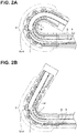
- a distal end portion 9f of a treatment instrument 9 moving inside of the channel tube 8 contacts a particular wire guide 7 through the channel tube 8 at substantially the same position (near an intermediate bending piece 5m4 in the drawing) inside of the bending portion 3 whether the bending angle of the bending portion 3 is 180° or larger as illustrated in Fig. 2A or 120° as illustrated in Fig. 2B .
- the present invention is intended to solve the above-described problem and provide an endoscope that prevents degradation of resistance at a particular site of a channel tube inserted and disposed in a bending portion.
- An endoscope includes: a bending portion provided on a distal end side of an insertion portion; a plurality of bending operation wires fixed on a distal end side of the bending portion; a wire insertion portion into which each of the bending operation wires is inserted in the bending portion; and a tubular body inserted and disposed in the insertion portion and including an axial-directional through-hole into which a treatment instrument is inserted.
- the bending portion includes a bending portion set including: a first bending piece set that includes a plurality of bending pieces rotatably coupled with each other and a wire insertion portion into which the bending operation wire is inserted to be guided to a proximal end side, a distal end of the bending operation wire being fixed on an inner surface of one of the plurality of bending pieces; a tubular bending tube that is a tubular member including a distal end portion rotatably coupled with a proximal end portion of the first bending piece set, is capable of bending through a plurality of slits arrayed in a longitudinal direction of the tubular member, each slit extending in a circumferential direction, and includes a wire insertion portion into which the bending operation wire is inserted from a distal end side to a proximal end side; and a second bending piece set that includes a plurality of bending pieces including a bending piece rotatably coupled with a proximal end
- the present invention described above can achieve an endoscope that prevents degradation of resistance at a particular site of a channel tube inserted and disposed in a bending portion.
- each drawing used in description below is schematically illustrated, and a dimensional relation, scaling, and the like of components are such that different scaling is applied to each configuration element to illustrate each configuration element in a recognizable manner in the drawings, and thus the present invention is not limited only by the number of configuration elements, shapes of the configuration elements, dimensional ratios of the configuration elements, and a relative positional relation between configuration elements illustrated in these drawings.
- an endoscope 10 includes an insertion portion 11, and an operation portion 12 continuously provided at a proximal end of the insertion portion 11, and a universal cord 13 extends from a side part of the operation portion 12.
- An endoscope connector 14 is provided at an end part of the universal cord 13.
- Reference sign 14c denotes an electric connector portion, and the electric connector portion 14c is detachably connected with an electric cable connected with a video processor (not illustrated) as an endoscope external device.
- the insertion portion 11 is an elongated tubular member having flexibility, and includes a distal end portion 15, a bending portion 16, and a flexible tube portion 17 provided continuously and sequentially from a distal end side.
- the distal end portion 15 includes an image pickup apparatus (not illustrated) including an image pickup device, an illumination optical system (not illustrated), and the like.
- the bending portion 16 is configured to bend, for example, upward and downward in two directions.
- the bending portion 16 is configured to perform a bending operation along with a rotational operation on a bending lever 19 as a bending operation member provided to the operation portion 12.
- the flexible tube portion 17 is a tubular member configured to passively perform elastic deformation.
- Bending operation wires (reference signs 21 and 22 in Figs. 4 and 5 ), a channel tube (refer to reference sign 18 in Fig. 7 ) as a tubular body that forms a treatment instrument insertion channel, various signal lines (not illustrated) extending from the image pickup apparatus, a light guide fiber bundle included in the illumination optical system, an electric cable that supplies electrical power to an LED, or the like is inserted in the insertion portion 11 described above.
- the bending portion 16 is configured to include a bending portion set 20 to be described later, a mesh tube (not illustrated), and a bending rubber (not illustrated).
- the mesh tube covers the bending portion set (refer to reference sign 20 in Figs. 4 and 5 ), and the bending rubber covers the mesh tube.
- the bending rubber is an outer skin as an outermost layer of the bending portion 16, and is a tubular elastic member made of, for example, elastomer.
- the bending portion 16 is not limited to a configuration that bends upward and downward in two directions, but may be configured to bend, for example, in four directions of the upward and downward directions and leftward and rightward directions.
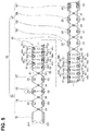
- the bending portion set 20 included in the bending portion 16 will be described below with reference to Figs. 4 and 5 .
- the bending portion set 20 includes a first bending piece set 30, a tubular bending tube 40, and a second bending piece set 50 provided continuously and sequentially from the distal end side.
- the first bending piece set 30 includes a first distal end bending piece 31 and a plurality of first intermediate bending pieces 32, and the bending pieces are rotatably coupled with each other by a coupling pin 34 and are configured to bend upward and downward in two directions.
- the distal end side of the first distal end bending piece 31 is integrally fixed to a distal end rigid member (not illustrated) included in the distal end portion 15.
- a distal end 21 f of the upper bending wire 21 and a distal end 22f of the lower bending wire 22 are fixed at predetermined positions on upper and lower parts, respectively, of an inner peripheral surface of the first distal end bending piece 31.
- Wire receivers 23 as wire insertion portions into which the upper bending wire 21 and the lower bending wire 22 are respectively inserted are provided at predetermined positions on upper and lower parts of an inner peripheral surface of each of the plurality of first intermediate bending pieces 32.
- the upper bending wire 21 and the lower bending wire 22 are inserted into the wire receivers 23 and guided to a proximal end side.
- the tubular bending tube 40 is a pipe member made of a super elastic alloy.
- the tubular bending tube 40 is rotatably coupled with the first intermediate bending pieces 32 on a most proximal end side of the first bending piece set 30 through the coupling pin 34.
- examples of the super elastic alloy member include Ni-Ti, ⁇ titanium alloy, and 64 titanium alloy.
- a plurality of partially arc-shaped slits (hereinafter simply referred to as slits) 41 and 42 are arrayed in the tubular bending tube 40.
- the tubular bending tube 40 includes the plurality of arrayed slits 41 and 42 and is configured to bend upward and downward in two directions.
- the slits 41 and 42 are each formed, for example, at a spread angle of 200° with respect to a central axis in a circumferential direction on an outer peripheral surface of the tubular bending tube 40.
- the first slit 41 and the second slit 42 adjacent to each other are separated from each other at a predetermined distance in an axial direction and at positions shifted from each other by 180° in the circumferential direction.
- These plurality of slits 41 and 42 are formed, for example, by laser fabrication.
- a plurality of guide fixation holes 43 are formed at predetermined positions of upper and lower parts of the tubular bending tube 40.
- a wire guide 44 is fixed to each guide fixation hole 43.
- the wire guide 44 is a wire insertion portion provided with wire insertion holes 44h into which the upper bending wire 21 and the lower bending wire 22 are respectively inserted from the distal end side toward the proximal end side.
- the second bending piece set 50 includes a plurality of second intermediate bending pieces 52, and a second proximal end bending piece 53, and the second intermediate bending piece 52 disposed on the distal end side among the plurality of second intermediate bending pieces 52 functions as a second distal end bending piece, and is rotatably coupled with a proximal end portion of the tubular bending tube 40 through the coupling pin 34.
- the bending pieces are rotatably coupled with each other through the coupling pin 34 and configured to bend upward and downward in two directions.
- the proximal end side of the second proximal end bending piece 53 is integrally fixed to a coupling tube (not illustrated) provided on the distal end side of the flexible tube portion 17.
- Wire guides 23 as wire insertion portions into which the upper bending wire 21 and the lower bending wire 22 are respectively inserted are provided at predetermined positions on upper and lower parts of an inner peripheral surface of the second intermediate bending piece 52.
- reference sign 24 denotes each of coil pipes into which the upper bending wire 21 and the lower bending wire 22 are respectively inserted.
- the wire guides 23 may be provided to the second proximal end bending piece 53.
- axial-directional lengths and end-edge tilt angles of the bending pieces 31 and 32 and the bending pieces 52 and 53 are set such that the bending portion set 20 has a bending radius of r in a maximum bending state.
- the bending piece sets 30 and 50 are each configured to include predetermined numbers of the intermediate bending pieces 32 and 52.
- the slits 41 and 42 are provided such that the tubular bending tube 40 has a bending radius of R in a maximum bending state. Note that, illustrations of the slits 41 and 42 are omitted in Fig. 6 .
- reference sign f denotes end edges.
- the end-edge tilt angle of each bending piece and the number of the second intermediate bending pieces 52 are sets such that an intersecting angle ⁇ between a longitudinal axis 11a of the insertion portion 11 and a bending portion set longitudinal axis 20a is smaller than, for example, 60° when the end edges of adjacent bending pieces are in contact with each other.
- Intervals, widths, and circumferential-directional spread angles of the slits 41 and 42 are set such that the tubular bending tube 40 is harder to bend than the second bending piece set 50, in other words, such that a bending stiffness of the tubular bending tube 40 is larger than a bending stiffness of the second bending piece set 50.
- a bending stiffness of the first bending piece set 30 is equivalent to the bending stiffness of the second bending piece set 50.
- the bending portion 16 provided in the insertion portion 11 is normally in a straight state, and the bending portion set 20 is in a straight-line state.
- the bending lever 19 is operated by an operator to pull, for example, the upper bending wire 21. Then, along with the pulling of the upper bending wire 21, bending starts at the second proximal end bending piece 53 of the second bending piece set 50 since the tubular bending tube 40 is configured to be harder to bend than the second bending piece set 50.
- the second intermediate bending piece 52 coupled with the second proximal end bending piece 53 through the coupling pin 34 (no reference sign provided in Fig. 6 ), and the second intermediate bending piece 52 coupled with the second intermediate bending piece 52 through the coupling pin 34 are rotated in the wire pull direction, and the bending portion 3 is gradually bent upward.
- the first bending piece set 30 having a bending stiffness equivalent to the bending stiffness of the second bending piece set 50 starts bending at the first intermediate bending pieces 32. Then, the end edges of the adjacent bending pieces 32 and 32, and the end edges of the bending pieces 32 and 31 are in contact with each other, thereby achieving a most bent state of the first bending piece set 30.
- the tubular bending tube 40 starts bending on the proximal end side. Then, as illustrated in Fig. 6D , the bending portion set 20 becomes the maximum bending state having the bending radius r.
- the channel tube 18 is inserted and disposed in the first bending piece set 30, the tubular bending tube 40, the second bending piece set 50, and the flexible tube portion 17.
- an insertion-disposition state of the channel tube 18 is deformed from a straight-line shape to a curved-line shape.
- the channel tube 18 is deformed mainly in the second bending piece set 50.
- a first curved portion R1 is formed in the channel tube 18 near the second bending piece set 50.
- a distal end portion 61 of a treatment instrument 60 that is moved inside of the channel tube 18 is smoothly moved toward a channel opening 18m without contacting the wire guides 23 through the channel tube.
- a second curved portion R2 is formed in the first bending piece set 30 as illustrated in Fig. 7C in addition to the first curved portion R1 in the second bending piece set 50.
- the second curved portion R2 is formed before the first bending piece set 30 comes to the most bent state, in other words, when the end edges of the plurality of first intermediate bending pieces 32 on the proximal end side are in contact with each other.
- the shape of the curved portion inside of the second bending piece set 50 does not largely change.
- the treatment instrument 60 moving inside of the channel tube 18 smoothly passes through the first curved portion R1. Then, the distal end portion 61 of the treatment instrument 60 is moved toward the channel opening 18m while being in contact with the wire guides 23 through the channel tube near the second curved portion R2.
- a third curved portion R3 is formed in the tubular bending tube 40 as illustrated in Fig. 7D in addition to the first curved portion R1 inside of the second bending piece set 50 and the second curved portion R2 inside of the first bending piece set 30.
- the third curved portion R3 is formed before the tubular bending tube 40 comes to the most bent state, in other words, when opening edges of the plurality of first slits 41 on the proximal end side are in contact with each other.
- the treatment instrument 60 moving inside of the channel tube 18 is moved toward the channel opening 18m as illustrated in Fig. 7D while being in contact with the wire guides 23 through the channel tube near a boundary between the first curved portion R1 and the third curved portion R3.
- the treatment instrument 60 smoothly moves inside of the channel tube 18.
- the treatment instrument 60 moves toward the channel opening 18m while being in contact with the wire guides 23 through the channel tube near the second curved portion R2.
- the treatment instrument 60 moves toward the channel opening 18m while being in contact with the wire guides 23 through the channel tube near the boundary between the first curved portion R1 and the third curved portion R3.
- the bending stiffness of the tubular bending tube 40 is set to be larger than the bending stiffness of the first bending piece set 30 and the bending stiffness of the second bending piece set 50, and then the first bending piece set 30, the tubular bending tube 40, and the second bending piece set 50 of the bending portion set 20 included in the bending portion 16 are provided continuously and sequentially from the distal end side.
- the second bending piece set 50, the first bending piece set 30, and the tubular bending tube 40 in the bending portion set 20 are sequentially bent without regularly bending from the proximal end side along with pulling of a bending wire, and thus the distal end portion 61 of the treatment instrument 60 moving inside of the channel tube 18 can be prevented from contacting the wire guides 23 through the channel tube at a particular place inside of the bending portion 16. As a result, a defect of degradation of a resistance at a particular site of the channel tube 18 is removed.
Landscapes
- Health & Medical Sciences (AREA)
- Life Sciences & Earth Sciences (AREA)
- Surgery (AREA)
- Physics & Mathematics (AREA)
- Optics & Photonics (AREA)
- Biomedical Technology (AREA)
- Animal Behavior & Ethology (AREA)
- Radiology & Medical Imaging (AREA)
- Nuclear Medicine, Radiotherapy & Molecular Imaging (AREA)
- Engineering & Computer Science (AREA)
- Biophysics (AREA)
- Heart & Thoracic Surgery (AREA)
- Medical Informatics (AREA)
- Molecular Biology (AREA)
- Pathology (AREA)
- General Health & Medical Sciences (AREA)
- Public Health (AREA)
- Veterinary Medicine (AREA)
- Rehabilitation Therapy (AREA)
- Astronomy & Astrophysics (AREA)
- General Physics & Mathematics (AREA)
- Endoscopes (AREA)
- Instruments For Viewing The Inside Of Hollow Bodies (AREA)
Abstract
Description
- The present invention relates to an endoscope including a bending portion in an insertion portion.
- Recently, an endoscope has been used in, for example, the medical and industrial fields. In the endoscope, an observation optical system for picking up an observation image of an observation site is provided at a distal end portion of an elongated insertion portion.
- A bending portion to allow easy insertion into an in-vivo deep part and allow the observation optical system provided at the distal end portion to face in a desired direction is provided on a distal end side of the insertion portion of the endoscope.
- The bending portion is configured to perform a bending operation toward a desired direction through a rotational operation on, for example, a rotational knob as a bending operation member provided at an operation portion of the endoscope.
- As illustrated in
Fig. 1A , aninsertion portion 1 is configured to include a distal endrigid portion 2, abending portion 3, and aflexible tube portion 4 provided juncturally and sequentially from the distal end side. Thebending portion 3 is typically configured to include a bending piece set 5, a mesh tube (not illustrated), and a bending rubber (not illustrated). - The bending piece set 5 includes a distal
end bending piece 5f of, for example, six intermediate bending pieces 5ml, ... 5m6, and a proximalend bending piece 5r, and the bending pieces are rotatably coupled with each other by acoupling pin 5p and configured to bend upward and downward in two directions. - Note that, the mesh tube covers the bending piece set 5, and the bending rubber is an outer skin as an outermost layer of the
bending portion 3 and covers, for example, an outer periphery of the mesh tube. -
Reference sign 6u denotes an upper bending wire (hereinafter simply referred to as an upper wire),reference sign 6d denotes a lower bending wire (hereinafter simply referred to as a lower wire), andreference sign 7 denotes a wire guide. Theupper wire 6u and thelower wire 6d are respectively inserted in the predeterminedwire guides 7. - Note that, the number of intermediate bending pieces is not limited to six, but may be larger or smaller than six. The
bending portion 3 is not limited to a configuration that bends upward and downward in two directions, but may be configured to bend upward, downward, leftward, and rightward in four directions, for example. - In the endoscope, when the rotational knob is operated to pull, for example, the
upper wire 6u, each of thebending pieces 5f, 5ml, ..., and 5r is rotated about acoupling pin 5p coupling the pieces to each other in a wire pull direction, so that thebending portion 3 bends in the upward direction. - The bending piece set 5 as the
bending portion 3 starts bending at the proximalend bending piece 5r illustrated inFig. 1B . Japanese Patent Application Laid-Open Publication No.2009-78012 - As illustrated in
Fig. 1C , when end edges of adjacent bending pieces become contact with each other, the bending piece set 5 becomes in a maximum bending state illustrated with dashed lines, having a bending angle of, for example, 180° or larger. In a state in which the end edges of adjacent bending pieces are in contact with each other, a bending radius is set to r. - Recently,
Japanese Patent No. 5444516 - The bending tube made of a super elastic alloy can achieve a bending portion with a simple configuration by providing, for example, a plurality of partially arc-shaped slits to a tubular member by laser fabrication or the like, without using, for example, a plurality of bending pieces and coupling pins. Setting of a bending radius and adjustment of bendability can be performed by setting intervals and the like of the slits provided to the bending tube as appropriate.
- Note that, when the intervals of the slits are set to be small, the bending radius becomes small and the bendability is improved.
- However, before a maximum bending state is reached, in the
bending portion 3, the end edges of adjacent bending pieces become in contact with each other at a certain bending angle or larger as illustrated inFig. 1B , a bending radius of the plurality of bending pieces bent from the proximal end side becomes r as indicated inFig. 1C . Thus, when a treatment instrument is introduced into achannel tube 8 inserted and disposed in thebending portion 3, adistal end portion 9f of atreatment instrument 9 moving inside of thechannel tube 8 contacts aparticular wire guide 7 through thechannel tube 8 at substantially the same position (near an intermediate bending piece 5m4 in the drawing) inside of thebending portion 3 whether the bending angle of thebending portion 3 is 180° or larger as illustrated inFig. 2A or 120° as illustrated inFig. 2B . - As a result, resistance potentially degrades extremely at part of the
channel tube 8 inserted and disposed in thebending portion 3. - The present invention is intended to solve the above-described problem and provide an endoscope that prevents degradation of resistance at a particular site of a channel tube inserted and disposed in a bending portion.
- An endoscope according to an aspect of the present invention includes: a bending portion provided on a distal end side of an insertion portion; a plurality of bending operation wires fixed on a distal end side of the bending portion;
a wire insertion portion into which each of the bending operation wires is inserted in the bending portion; and a tubular body inserted and disposed in the insertion portion and including an axial-directional through-hole into which a treatment instrument is inserted. The bending portion includes a bending portion set including: a first bending piece set that includes a plurality of bending pieces rotatably coupled with each other and a wire insertion portion into which the bending operation wire is inserted to be guided to a proximal end side, a distal end of the bending operation wire being fixed on an inner surface of one of the plurality of bending pieces; a tubular bending tube that is a tubular member including a distal end portion rotatably coupled with a proximal end portion of the first bending piece set, is capable of bending through a plurality of slits arrayed in a longitudinal direction of the tubular member, each slit extending in a circumferential direction, and includes a wire insertion portion into which the bending operation wire is inserted from a distal end side to a proximal end side; and a second bending piece set that includes a plurality of bending pieces including a bending piece rotatably coupled with a proximal end portion of the tubular bending tube and includes a wire insertion portion into which the bending operation wire is inserted from a distal end side to a proximal end side. - The present invention described above can achieve an endoscope that prevents degradation of resistance at a particular site of a channel tube inserted and disposed in a bending portion.
-
-
Fig. 1A is a diagram for description of a bending piece set configured by a plurality of bending pieces juncturally provided; -
Fig. 1B is a diagram for description of the bending piece set configured by a plurality of bending pieces juncturally provided; -
Fig. 1C is a diagram for description of the bending piece set configured by a plurality of bending pieces juncturally provided; -
Fig. 2A is a diagram for description of a defect of contact of a treatment instrument moving inside of a channel tube inserted and disposed in a bending portion being bent with a particular wire guide; -
Fig. 2B is a diagram for description of the defect of contact of the treatment instrument moving inside of the channel tube inserted and disposed in the bending portion being bent with a particular wire guide; -
Fig. 3 is a diagram for description of an endoscope characterized in the bending portion; -
Fig. 4 is a diagram for description of a configuration of a bending portion set included in the bending portion; -
Fig. 5 is a longitudinal cross-sectional view for description of the configuration of the bending portion set; -
Fig. 6A is a diagram for description of a bending operation of the bending portion set; -
Fig. 6B is a diagram for description of the bending operation of the bending portion set; -
Fig. 6C is a diagram for description of the bending operation of the bending portion set; -
Fig. 6D is a diagram for description of the bending operation of the bending portion set; -
Fig. 7A is a diagram for description of a relation between a channel tube inside of the bending portion and a treatment instrument moving inside of the channel tube; -
Fig. 7B is a diagram for description of the relation between the channel tube inside of the bending portion and the treatment instrument moving inside of the channel tube; -
Fig. 7C is a diagram for description of the relation between the channel tube inside of the bending portion and the treatment instrument moving inside of the channel tube; and -
Fig. 7D is a diagram for description of the relation between the channel tube inside of the bending portion and the treatment instrument moving inside of the channel tube. - Embodiments of the present invention will be described below with reference to the accompanying drawings.
- Note that, each drawing used in description below is schematically illustrated, and a dimensional relation, scaling, and the like of components are such that different scaling is applied to each configuration element to illustrate each configuration element in a recognizable manner in the drawings, and thus the present invention is not limited only by the number of configuration elements, shapes of the configuration elements, dimensional ratios of the configuration elements, and a relative positional relation between configuration elements illustrated in these drawings.
- As illustrated in
Fig. 3 , anendoscope 10 according to the present embodiment includes aninsertion portion 11, and anoperation portion 12 continuously provided at a proximal end of theinsertion portion 11, and auniversal cord 13 extends from a side part of theoperation portion 12. - An
endoscope connector 14 is provided at an end part of theuniversal cord 13.Reference sign 14c denotes an electric connector portion, and theelectric connector portion 14c is detachably connected with an electric cable connected with a video processor (not illustrated) as an endoscope external device. Theinsertion portion 11 is an elongated tubular member having flexibility, and includes adistal end portion 15, a bendingportion 16, and aflexible tube portion 17 provided continuously and sequentially from a distal end side. Thedistal end portion 15 includes an image pickup apparatus (not illustrated) including an image pickup device, an illumination optical system (not illustrated), and the like. - The bending
portion 16 is configured to bend, for example, upward and downward in two directions. The bendingportion 16 is configured to perform a bending operation along with a rotational operation on a bendinglever 19 as a bending operation member provided to theoperation portion 12. - The
flexible tube portion 17 is a tubular member configured to passively perform elastic deformation. - Bending operation wires (reference signs 21 and 22 in
Figs. 4 and5 ), a channel tube (refer toreference sign 18 inFig. 7 ) as a tubular body that forms a treatment instrument insertion channel, various signal lines (not illustrated) extending from the image pickup apparatus, a light guide fiber bundle included in the illumination optical system, an electric cable that supplies electrical power to an LED, or the like is inserted in theinsertion portion 11 described above. - Note that, the bending
portion 16 is configured to include a bending portion set 20 to be described later, a mesh tube (not illustrated), and a bending rubber (not illustrated). - The mesh tube covers the bending portion set (refer to
reference sign 20 inFigs. 4 and5 ), and the bending rubber covers the mesh tube. The bending rubber is an outer skin as an outermost layer of the bendingportion 16, and is a tubular elastic member made of, for example, elastomer. The bendingportion 16 is not limited to a configuration that bends upward and downward in two directions, but may be configured to bend, for example, in four directions of the upward and downward directions and leftward and rightward directions. - The bending portion set 20 included in the bending
portion 16 will be described below with reference toFigs. 4 and5 . - As illustrated in
Figs. 4 and5 , the bending portion set 20 includes a first bending piece set 30, atubular bending tube 40, and a second bending piece set 50 provided continuously and sequentially from the distal end side. - The first bending piece set 30 includes a first distal
end bending piece 31 and a plurality of firstintermediate bending pieces 32, and the bending pieces are rotatably coupled with each other by acoupling pin 34 and are configured to bend upward and downward in two directions. - The distal end side of the first distal
end bending piece 31 is integrally fixed to a distal end rigid member (not illustrated) included in thedistal end portion 15. Adistal end 21 f of theupper bending wire 21 and adistal end 22f of thelower bending wire 22 are fixed at predetermined positions on upper and lower parts, respectively, of an inner peripheral surface of the first distalend bending piece 31. -
Wire receivers 23 as wire insertion portions into which theupper bending wire 21 and thelower bending wire 22 are respectively inserted are provided at predetermined positions on upper and lower parts of an inner peripheral surface of each of the plurality of firstintermediate bending pieces 32. Theupper bending wire 21 and thelower bending wire 22 are inserted into thewire receivers 23 and guided to a proximal end side. - The
tubular bending tube 40 is a pipe member made of a super elastic alloy. Thetubular bending tube 40 is rotatably coupled with the firstintermediate bending pieces 32 on a most proximal end side of the first bending piece set 30 through thecoupling pin 34. - Note that, examples of the super elastic alloy member include Ni-Ti, β titanium alloy, and 64 titanium alloy.
- A plurality of partially arc-shaped slits (hereinafter simply referred to as slits) 41 and 42 are arrayed in the
tubular bending tube 40. Thetubular bending tube 40 includes the plurality of arrayedslits - The
slits tubular bending tube 40. Thefirst slit 41 and thesecond slit 42 adjacent to each other are separated from each other at a predetermined distance in an axial direction and at positions shifted from each other by 180° in the circumferential direction. - These plurality of
slits - A plurality of guide fixation holes 43 are formed at predetermined positions of upper and lower parts of the
tubular bending tube 40. Awire guide 44 is fixed to each guidefixation hole 43. - The
wire guide 44 is a wire insertion portion provided withwire insertion holes 44h into which theupper bending wire 21 and thelower bending wire 22 are respectively inserted from the distal end side toward the proximal end side. The second bending piece set 50 includes a plurality of secondintermediate bending pieces 52, and a second proximalend bending piece 53, and the secondintermediate bending piece 52 disposed on the distal end side among the plurality of secondintermediate bending pieces 52 functions as a second distal end bending piece, and is rotatably coupled with a proximal end portion of thetubular bending tube 40 through thecoupling pin 34. The bending pieces are rotatably coupled with each other through thecoupling pin 34 and configured to bend upward and downward in two directions. - The proximal end side of the second proximal
end bending piece 53 is integrally fixed to a coupling tube (not illustrated) provided on the distal end side of theflexible tube portion 17. Wire guides 23 as wire insertion portions into which theupper bending wire 21 and thelower bending wire 22 are respectively inserted are provided at predetermined positions on upper and lower parts of an inner peripheral surface of the secondintermediate bending piece 52. - Note that,
reference sign 24 denotes each of coil pipes into which theupper bending wire 21 and thelower bending wire 22 are respectively inserted. Instead of thecoil pipes 24, the wire guides 23 may be provided to the second proximalend bending piece 53. - As illustrated in
Fig. 6D , axial-directional lengths and end-edge tilt angles of the bendingpieces pieces Fig. 6A , the bending piece sets 30 and 50 are each configured to include predetermined numbers of theintermediate bending pieces slits tubular bending tube 40 has a bending radius of R in a maximum bending state. Note that, illustrations of theslits Fig. 6 . InFig. 6A , reference sign f denotes end edges. - As illustrated in
Fig. 6B , as for the second bending piece set 50, the end-edge tilt angle of each bending piece and the number of the secondintermediate bending pieces 52 are sets such that an intersecting angle θ between alongitudinal axis 11a of theinsertion portion 11 and a bending portion setlongitudinal axis 20a is smaller than, for example, 60° when the end edges of adjacent bending pieces are in contact with each other. - Intervals, widths, and circumferential-directional spread angles of the
slits tubular bending tube 40 is harder to bend than the second bending piece set 50, in other words, such that a bending stiffness of thetubular bending tube 40 is larger than a bending stiffness of the second bending piece set 50. - Note that, a bending stiffness of the first bending piece set 30 is equivalent to the bending stiffness of the second bending piece set 50.
- An effect of the bending
portion 16 provided in theinsertion portion 11 will be described. - As illustrated in
Fig. 6A , the bendingportion 16 provided in theinsertion portion 11 is normally in a straight state, and the bending portion set 20 is in a straight-line state. - The bending
lever 19 is operated by an operator to pull, for example, theupper bending wire 21. Then, along with the pulling of theupper bending wire 21, bending starts at the second proximalend bending piece 53 of the second bending piece set 50 since thetubular bending tube 40 is configured to be harder to bend than the second bending piece set 50. - Specifically, the second
intermediate bending piece 52 coupled with the second proximalend bending piece 53 through the coupling pin 34 (no reference sign provided inFig. 6 ), and the secondintermediate bending piece 52 coupled with the secondintermediate bending piece 52 through thecoupling pin 34 are rotated in the wire pull direction, and the bendingportion 3 is gradually bent upward. - Then, as illustrated in
Fig. 6B , the end edges of theadjacent bending pieces pieces - When the bending
lever 19 is further operated by the operator, theupper bending wire 21 is further pulled, and thetubular bending tube 40 coupled with the second bending piece set 50 through thecoupling pin 34 is rotated in the wire pull direction as illustrated with dashed lines inFig. 6B , so that the end edge of thetubular bending tube 40 on the proximal end side becomes in contact with the end edge of the secondintermediate bending piece 52, and a bending angle of the bending portion becomes large. - When the bending
lever 19 is further operated by the operator while the end edge of thetubular bending tube 40 on the proximal end side is in contact with the end edge of the secondintermediate bending piece 52, the bending portion set 20 is bent as illustrated inFigs. 6C and (D. - As illustrated in
Fig. 6C , along with the pulling of theupper bending wire 21, the first bending piece set 30 having a bending stiffness equivalent to the bending stiffness of the second bending piece set 50 starts bending at the firstintermediate bending pieces 32. Then, the end edges of theadjacent bending pieces pieces - Thereafter, along with the pulling of the
upper bending wire 21, thetubular bending tube 40 starts bending on the proximal end side. Then, as illustrated inFig. 6D , the bending portion set 20 becomes the maximum bending state having the bending radius r. - A treatment instrument that moves inside of an axial-directional through-
hole 18h of thechannel tube 18 inserted and disposed in the bending portion set 20 being bent as described above will be described with reference toFig. 7A-(D . - As illustrated in
Fig. 7A , thechannel tube 18 is inserted and disposed in the first bending piece set 30, thetubular bending tube 40, the second bending piece set 50, and theflexible tube portion 17. Along with a change in a bending shape of the bendingportion 16 described above, an insertion-disposition state of thechannel tube 18 is deformed from a straight-line shape to a curved-line shape. - As illustrated in
Fig. 7B , in a state in which the second bending piece set 50 is bent, thechannel tube 18 is deformed mainly in the second bending piece set 50. In the most bent state of the second bending piece set 50, a first curved portion R1 is formed in thechannel tube 18 near the second bending piece set 50. - In the first curved portion R1 formed in the second bending piece set 50 in which predetermined bending pieces are arrayed, a
distal end portion 61 of atreatment instrument 60 that is moved inside of thechannel tube 18 is smoothly moved toward achannel opening 18m without contacting the wire guides 23 through the channel tube. - In a state in which the end edge of the
tubular bending tube 40 on the proximal end side is made contact with the end edge of the secondintermediate bending piece 52 so that the bending angle becomes large, a shape of the curved portion inside of the second bending piece set 50 does not change largely. Thus, the treatment instrument is moved toward thechannel opening 18m, smoothly passing through inside of the curved portion of the second bending piece set 50. - When the first bending piece set 30 is bent in addition to the second bending piece set 50, in the
channel tube 18, a second curved portion R2 is formed in the first bending piece set 30 as illustrated inFig. 7C in addition to the first curved portion R1 in the second bending piece set 50. - Note that, the second curved portion R2 is formed before the first bending piece set 30 comes to the most bent state, in other words, when the end edges of the plurality of first
intermediate bending pieces 32 on the proximal end side are in contact with each other. In a state in which the second curved portion R2 is formed in the first bending piece set 30, the shape of the curved portion inside of the second bending piece set 50 does not largely change. - Thus, as illustrated in
Fig. 7C , thetreatment instrument 60 moving inside of thechannel tube 18 smoothly passes through the first curved portion R1. Then, thedistal end portion 61 of thetreatment instrument 60 is moved toward thechannel opening 18m while being in contact with the wire guides 23 through the channel tube near the second curved portion R2. - When the
tubular bending tube 40 is bent in addition to the second bending piece set 50 and the first bending piece set 30, in thechannel tube 18, a third curved portion R3 is formed in thetubular bending tube 40 as illustrated inFig. 7D in addition to the first curved portion R1 inside of the second bending piece set 50 and the second curved portion R2 inside of the first bending piece set 30. - Note that, the third curved portion R3 is formed before the
tubular bending tube 40 comes to the most bent state, in other words, when opening edges of the plurality offirst slits 41 on the proximal end side are in contact with each other. - Then, when the third curved portion R3 is formed in the
channel tube 18 inside of thetubular bending tube 40, thetreatment instrument 60 moving inside of thechannel tube 18 is moved toward thechannel opening 18m as illustrated inFig. 7D while being in contact with the wire guides 23 through the channel tube near a boundary between the first curved portion R1 and the third curved portion R3. - That is, in a state in which the first curved portion R1 is formed, the
treatment instrument 60 smoothly moves inside of thechannel tube 18. However, in a state in which the second curved portion R2 is formed in addition to the first curved portion R1, thetreatment instrument 60 moves toward thechannel opening 18m while being in contact with the wire guides 23 through the channel tube near the second curved portion R2. In a state in which the third curved portion R3 is formed in addition to the first curved portion R1 and the second curved portion R2, thetreatment instrument 60 moves toward thechannel opening 18m while being in contact with the wire guides 23 through the channel tube near the boundary between the first curved portion R1 and the third curved portion R3. - As described above, the bending stiffness of the
tubular bending tube 40 is set to be larger than the bending stiffness of the first bending piece set 30 and the bending stiffness of the second bending piece set 50, and then the first bending piece set 30, thetubular bending tube 40, and the second bending piece set 50 of the bending portion set 20 included in the bendingportion 16 are provided continuously and sequentially from the distal end side. As a result, the second bending piece set 50, the first bending piece set 30, and thetubular bending tube 40 in the bending portion set 20 are sequentially bent without regularly bending from the proximal end side along with pulling of a bending wire, and thus thedistal end portion 61 of thetreatment instrument 60 moving inside of thechannel tube 18 can be prevented from contacting the wire guides 23 through the channel tube at a particular place inside of the bendingportion 16. As a result, a defect of degradation of a resistance at a particular site of thechannel tube 18 is removed. - The present invention is not limited only to the above-described embodiment, but various modifications may be performed without departing from the scope of the invention.
- The present application is made by using Japanese Patent Application No.
2014-205853 filed on October 6, 2014
Claims (4)
- An endoscope comprising:a bending portion provided on a distal end side of an insertion portion;a plurality of bending operation wires fixed on a distal end side of the bending portion;a wire insertion portion into which each of the bending operation wires is inserted in the bending portion; anda tubular body inserted and disposed in the insertion portion and including an axial-directional through-hole into which a treatment instrument is inserted,wherein the bending portion includes a bending portion set including: a first bending piece set that includes a plurality of bending pieces rotatably coupled with each other and a wire insertion portion into which the bending operation wire is inserted to be guided to a proximal end side, a distal end of the bending operation wire being fixed on an inner surface of one of the plurality of bending pieces; a tubular bending tube that is a tubular member including a distal end portion rotatably coupled with a proximal end portion of the first bending piece set, is capable of bending through a plurality of slits arrayed in a longitudinal direction of the tubular member, each slit extending in a circumferential direction, and includes a wire insertion portion into which the bending operation wire is inserted from a distal end side to a proximal end side; and a second bending piece set that includes a plurality of bending pieces including a bending piece rotatably coupled with a proximal end portion of the tubular bending tube and includes a wire insertion portion into which the bending operation wire is inserted from a distal end side to a proximal end side.
- The endoscope according to claim 1, wherein a bending stiffness of the tubular bending tube is set to be larger than a bending stiffness of the second bending piece set.
- The endoscope according to claim 1, wherein the tubular bending tube is a super elastic pipe member.
- The endoscope according to claim 3, wherein the super elastic pipe member is made of Ni-Ti.
Applications Claiming Priority (2)
| Application Number | Priority Date | Filing Date | Title |
|---|---|---|---|
| JP2014205853 | 2014-10-06 | ||
| PCT/JP2015/077284 WO2016056417A1 (en) | 2014-10-06 | 2015-09-28 | Endoscope |
Publications (2)
| Publication Number | Publication Date |
|---|---|
| EP3175768A1 true EP3175768A1 (en) | 2017-06-07 |
| EP3175768A4 EP3175768A4 (en) | 2018-04-11 |
Family
ID=55653034
Family Applications (1)
| Application Number | Title | Priority Date | Filing Date |
|---|---|---|---|
| EP15848542.5A Withdrawn EP3175768A4 (en) | 2014-10-06 | 2015-09-28 | Endoscope |
Country Status (5)
| Country | Link |
|---|---|
| US (1) | US20170172385A1 (en) |
| EP (1) | EP3175768A4 (en) |
| JP (1) | JP6043027B2 (en) |
| CN (1) | CN107072472B (en) |
| WO (1) | WO2016056417A1 (en) |
Families Citing this family (11)
| Publication number | Priority date | Publication date | Assignee | Title |
|---|---|---|---|---|
| EP3265160B1 (en) * | 2015-03-02 | 2018-12-19 | Koninklijke Philips N.V. | Variable configuration bending neck for an articulating ultrasound probe |
| WO2020031378A1 (en) | 2018-08-10 | 2020-02-13 | オリンパス株式会社 | Endoscope |
| CN109528149A (en) * | 2018-12-25 | 2019-03-29 | 深圳市先赞科技有限公司 | Endoscope |
| EP3968837B1 (en) * | 2019-05-15 | 2025-02-26 | Boston Scientific Scimed, Inc. | Medical device having asymmetric bending |
| JPWO2021229792A1 (en) * | 2020-05-15 | 2021-11-18 | ||
| CN111761609B (en) * | 2020-07-08 | 2022-06-03 | 天津大学 | Flexible continuum robot based on contact-assisted structure |
| JP2022035058A (en) * | 2020-08-20 | 2022-03-04 | 株式会社Biomedical Solutions | Biopsy forceps |
| CN112890740A (en) * | 2021-03-19 | 2021-06-04 | 深圳开立生物医疗科技股份有限公司 | Insertion device and endoscope |
| DE102021115475A1 (en) * | 2021-06-15 | 2022-12-15 | Konstantin Bob | Tilting mechanism for an endoscope |
| CN113456231B (en) * | 2021-07-22 | 2022-08-12 | 上海交通大学 | A notch-type continuum robot based on a cross-bending beam structure |
| CN116421127B (en) * | 2023-03-01 | 2025-11-21 | 浙江优亿医疗器械股份有限公司 | Endoscope and snake bone structure thereof |
Family Cites Families (25)
| Publication number | Priority date | Publication date | Assignee | Title |
|---|---|---|---|---|
| JPH01181835A (en) * | 1988-01-14 | 1989-07-19 | Olympus Optical Co Ltd | Endoscope |
| US6749560B1 (en) * | 1999-10-26 | 2004-06-15 | Circon Corporation | Endoscope shaft with slotted tube |
| US6780151B2 (en) * | 1999-10-26 | 2004-08-24 | Acmi Corporation | Flexible ureteropyeloscope |
| US6485411B1 (en) * | 2000-04-12 | 2002-11-26 | Circon Corporation | Endoscope shaft with superelastic alloy spiral frame and braid |
| JP3776767B2 (en) * | 2000-10-02 | 2006-05-17 | オリンパス株式会社 | Endoscope |
| JP2002209832A (en) * | 2001-01-12 | 2002-07-30 | Olympus Optical Co Ltd | Endoscope |
| US20040225186A1 (en) * | 2003-01-29 | 2004-11-11 | Horne Guy E. | Composite flexible endoscope insertion shaft with tubular substructure |
| US7678117B2 (en) * | 2004-06-07 | 2010-03-16 | Novare Surgical Systems, Inc. | Articulating mechanism with flex-hinged links |
| WO2005123169A1 (en) * | 2004-06-14 | 2005-12-29 | Applied Medical Resources Corporation | Steerable vascular sheath |
| JP4323441B2 (en) * | 2005-02-14 | 2009-09-02 | オリンパス株式会社 | Endoscope |
| US8052597B2 (en) * | 2005-08-30 | 2011-11-08 | Boston Scientific Scimed, Inc. | Method for forming an endoscope articulation joint |
| US8007434B2 (en) * | 2006-03-06 | 2011-08-30 | Boston Scientific Scimed, Inc. | Variable stiffness medical device shaft |
| US8992422B2 (en) * | 2006-03-23 | 2015-03-31 | Ethicon Endo-Surgery, Inc. | Robotically-controlled endoscopic accessory channel |
| JP5364326B2 (en) * | 2008-02-01 | 2013-12-11 | 富士フイルム株式会社 | Endoscope |
| ES2750844T3 (en) * | 2008-03-10 | 2020-03-27 | Fortimedix Surgical B V | Instrument for endoscopic applications |
| US20110276034A1 (en) * | 2009-01-15 | 2011-11-10 | Cathrx Ltd | Steerable stylet |
| JP2010167180A (en) * | 2009-01-26 | 2010-08-05 | Fujifilm Corp | Endoscope |
| US20110112365A1 (en) * | 2009-06-03 | 2011-05-12 | Gyrus Acmi, Inc. | Endoscope shaft |
| US20100331618A1 (en) * | 2009-06-24 | 2010-12-30 | Gyrus Acmi, Inc. | Endoscope shaft frame member with wavy slot |
| EP2505117B1 (en) * | 2010-03-08 | 2014-04-16 | Olympus Medical Systems Corp. | Medical device for multiple bends |
| US9795765B2 (en) * | 2010-04-09 | 2017-10-24 | St. Jude Medical International Holding S.À R.L. | Variable stiffness steering mechanism for catheters |
| CN103764216B (en) * | 2011-05-03 | 2016-08-17 | 施菲姆德控股有限责任公司 | Steerable Delivery Sheath |
| EP2753292B1 (en) * | 2011-09-08 | 2018-06-27 | Unilever N.V. | Tooth remineralizing dentifrice |
| WO2013190910A1 (en) * | 2012-06-22 | 2013-12-27 | オリンパスメディカルシステムズ株式会社 | Bending tube and medical instrument |
| US8967204B2 (en) * | 2012-08-24 | 2015-03-03 | Olympus Medical Systems Corporation | Curved pipe for endoscopes |
-
2015
- 2015-09-28 CN CN201580051463.3A patent/CN107072472B/en active Active
- 2015-09-28 EP EP15848542.5A patent/EP3175768A4/en not_active Withdrawn
- 2015-09-28 WO PCT/JP2015/077284 patent/WO2016056417A1/en not_active Ceased
- 2015-09-28 JP JP2016524159A patent/JP6043027B2/en active Active
-
2017
- 2017-03-06 US US15/450,070 patent/US20170172385A1/en not_active Abandoned
Also Published As
| Publication number | Publication date |
|---|---|
| EP3175768A4 (en) | 2018-04-11 |
| WO2016056417A1 (en) | 2016-04-14 |
| JP6043027B2 (en) | 2016-12-14 |
| CN107072472A (en) | 2017-08-18 |
| US20170172385A1 (en) | 2017-06-22 |
| CN107072472B (en) | 2019-07-12 |
| JPWO2016056417A1 (en) | 2017-04-27 |
Similar Documents
| Publication | Publication Date | Title |
|---|---|---|
| EP3175768A1 (en) | Endoscope | |
| CN106455910B (en) | Endoscope-use swan-neck and endoscope with the endoscope-use swan-neck | |
| EP2959823A1 (en) | Endoscope | |
| CN105828690B (en) | endoscope | |
| JP4323441B2 (en) | Endoscope | |
| JP5897237B1 (en) | Endoscope | |
| US9192288B2 (en) | Endoscope | |
| US10493240B2 (en) | Steerable catheter handle | |
| EP2457491B1 (en) | Endoscope | |
| JP5228161B2 (en) | Endoscope bending device | |
| JP6854913B2 (en) | Endoscope devices, medical devices and strips | |
| EP3135182A1 (en) | Endoscope bending section and endoscope | |
| JPWO2014208333A1 (en) | Spiral unit and introduction device | |
| CN105208910B (en) | Medical device | |
| US11882998B2 (en) | Endoscope | |
| JP2010068891A (en) | Endoscope | |
| JP2018175225A (en) | Endoscope system | |
| EP3490428B1 (en) | Steerable catheter handle | |
| CN112423642B (en) | Endoscope with a lens | |
| JP2009089724A (en) | Separate type endoscope | |
| JP2010042120A (en) | Endoscope | |
| WO2018116557A1 (en) | Bendable tube structure and endoscope |
Legal Events
| Date | Code | Title | Description |
|---|---|---|---|
| STAA | Information on the status of an ep patent application or granted ep patent |
Free format text: STATUS: THE INTERNATIONAL PUBLICATION HAS BEEN MADE |
|
| 17P | Request for examination filed |
Effective date: 20170303 |
|
| AK | Designated contracting states |
Kind code of ref document: A1 Designated state(s): AL AT BE BG CH CY CZ DE DK EE ES FI FR GB GR HR HU IE IS IT LI LT LU LV MC MK MT NL NO PL PT RO RS SE SI SK SM TR |
|
| AX | Request for extension of the european patent |
Extension state: BA ME |
|
| PUAI | Public reference made under article 153(3) epc to a published international application that has entered the european phase |
Free format text: ORIGINAL CODE: 0009012 |
|
| STAA | Information on the status of an ep patent application or granted ep patent |
Free format text: STATUS: REQUEST FOR EXAMINATION WAS MADE |
|
| DAV | Request for validation of the european patent (deleted) | ||
| DAX | Request for extension of the european patent (deleted) | ||
| A4 | Supplementary search report drawn up and despatched |
Effective date: 20180312 |
|
| RIC1 | Information provided on ipc code assigned before grant |
Ipc: G02B 23/24 20060101ALI20180306BHEP Ipc: A61B 1/00 20060101AFI20180306BHEP |
|
| STAA | Information on the status of an ep patent application or granted ep patent |
Free format text: STATUS: THE APPLICATION IS DEEMED TO BE WITHDRAWN |
|
| 18D | Application deemed to be withdrawn |
Effective date: 20181009 |