EP3175743A1 - Drum assembly having pulp discharge control device, and juicer including same - Google Patents
Drum assembly having pulp discharge control device, and juicer including same Download PDFInfo
- Publication number
- EP3175743A1 EP3175743A1 EP15827591.7A EP15827591A EP3175743A1 EP 3175743 A1 EP3175743 A1 EP 3175743A1 EP 15827591 A EP15827591 A EP 15827591A EP 3175743 A1 EP3175743 A1 EP 3175743A1
- Authority
- EP
- European Patent Office
- Prior art keywords
- pulp
- discharge
- opening
- pulp discharge
- discharge resistance
- Prior art date
- Legal status (The legal status is an assumption and is not a legal conclusion. Google has not performed a legal analysis and makes no representation as to the accuracy of the status listed.)
- Granted
Links
Images









Classifications
-
- A—HUMAN NECESSITIES
- A23—FOODS OR FOODSTUFFS; TREATMENT THEREOF, NOT COVERED BY OTHER CLASSES
- A23N—MACHINES OR APPARATUS FOR TREATING HARVESTED FRUIT, VEGETABLES OR FLOWER BULBS IN BULK, NOT OTHERWISE PROVIDED FOR; PEELING VEGETABLES OR FRUIT IN BULK; APPARATUS FOR PREPARING ANIMAL FEEDING- STUFFS
- A23N1/00—Machines or apparatus for extracting juice
- A23N1/02—Machines or apparatus for extracting juice combined with disintegrating or cutting
-
- A—HUMAN NECESSITIES
- A47—FURNITURE; DOMESTIC ARTICLES OR APPLIANCES; COFFEE MILLS; SPICE MILLS; SUCTION CLEANERS IN GENERAL
- A47J—KITCHEN EQUIPMENT; COFFEE MILLS; SPICE MILLS; APPARATUS FOR MAKING BEVERAGES
- A47J19/00—Household machines for straining foodstuffs; Household implements for mashing or straining foodstuffs
- A47J19/02—Citrus fruit squeezers; Other fruit juice extracting devices
- A47J19/025—Citrus fruit squeezers; Other fruit juice extracting devices including a pressing screw
Definitions
- Embodiments of the present disclosure relate to a drum assembly having a pulp discharge adjusting apparatus, and a juicer comprising the same, and more particularly, to a drum assembly having a pulp discharge adjusting apparatus for adjusting an amount of pulps discharged from a drum body according to a type of a subject being extracted or a user preference, and a juicer comprising the same.
- Juicers are electronic appliances used to directly squeeze out fruit juice or vegetable juice from fruits or vegetables for drinks.
- a variety of juicers are introduced to help home users to conveniently extract juice from vegetables or fruits for their healthy lives.
- a juicer receives a subject being extracted (e.g., fruit or vegetable) in a drum in which an extraction screw is rotatably mounted, and crushes the subject being extracted and squeezes out juice therefrom by rotating the extraction screw with a driving portion located under the drum. After crushing and squeezing by the extraction screw, the subject being extracted is separated by an extraction net into juice and pulp, then the separated juice and pulp are expelled out through a juice discharge port and a pump discharge port, respectively.
- a subject being extracted e.g., fruit or vegetable
- a driving portion located under the drum.
- Korean Patent Publication No. 2013-0028535 discloses a juicer having a pulp opening and closing equipment
- US Patent Publication No. 2007-0277682 discloses a juicer capable of adjusting an amount of juice extraction with a wetness control unit.
- Exemplary embodiments of the present inventive concept overcome the above disadvantages and other disadvantages not described above. Also, the present inventive concept is not required to overcome the disadvantages described above, and an exemplary embodiment of the present inventive concept may not overcome any of the problems described above.
- a drum assembly for a juicer in which comprises a drum body having a juice discharge port and at least one pulp discharge port, and a pulp discharge adjusting apparatus mounted on the pulp discharge port to adjust an amount of pulp discharge.
- the pulp discharge adjusting apparatus may comprise a discharge resistance exerting member installed in the pulp discharge port to exert a discharge resistance on a pulp being discharged through the pulp discharge port, and having an elastically deformable portion which is elastically deformable by pressing of the pulp being discharged, and a discharge resistance adjusting member operated by a user to adjust the discharge resistance.
- the pulp discharge adjusting apparatus may further comprise a connecting member coupled with the discharge resistance exerting member and the discharge resistance adjusting member, respectively, and guiding a movement of the discharge resistance adjusting member during adjustment of the discharge resistance.
- the discharge resistance adjusting member may be coupled with the connecting member such that the discharge resistance adjusting member is slidable between a first position of contacting an outer surface of the elastically deformable portion and a second position of being spaced from the outer surface of the elastically deformable portion.
- the connecting member is attachable to or detachable from the pulp discharge port in a state of being coupled with the discharge resistance exerting member and the discharge resistance adjusting member.
- the discharge resistance adjusting member may be disposed to be in contact with an upper region of the elastically deformable portion and is rotatably coupled with the connecting member, and the discharge resistance adjusting member may have a shape with a variable distance between a lower end of the discharge resistance adjusting member and a lower end of the elastically deformable portion according to a rotation thereof.
- the discharge resistance adjusting member may have a shape of a ring penetrated by the connecting member, and an outer circumferential surface of the discharge resistance adjusting member may comprise a plurality of flat edge surfaces at different distances from an axis of rotation.
- the discharge resistance adjusting member may comprise an operating portion rotatably coupled with the connecting member and partially exposed outside the pulp discharge port, and a contacting portion provided on an inner end of the operating portion and disposed to be in contact with the upper region of the elastically deformable portion.
- the contacting portion may be provided as a plate shape, and an outer circumferential surface of the contacting portion comprises a plurality of flat edge surfaces at different distances from an axis of rotation.
- the contacting portion may be provided as a plate shape, and an outer circumferential surface of the contacting portion is formed as a curved surface at a variable distance from an axis of rotation.
- the pulp discharge adjusting apparatus may comprise an opening/closing member for opening and closing a pulp discharge opening of the drum body, and an operating member coupled with the opening/closing member and rotatably mounted on the pulp discharge port.
- An opening degree of the pulp discharge opening by the opening/closing member may be adjusted according to the rotation of the operating member.
- the pulp discharge port may have a shape with an open upper side, the operating member may be disposed within the pulp discharge port, and the operating member may have a protecting protrusion provided on one side to prevent a finger from entering the pulp discharge opening.
- the drum body may comprise a first pulp discharge port in fluid communication with the first pulp discharge opening, and a second pulp discharge port in fluid communication with the second pulp discharge opening and disposed over the juice discharge port, and a first and a second pulp discharge adjusting apparatuses may be installed in the first and the second pulp discharge ports, respectively.
- the first pulp discharge adjusting apparatus may comprise a discharge resistance exerting member installed in the pulp discharge port to exert discharge resistance on a pulp being discharged through the first pulp discharge port, and having an elastically deformable portion which is elastically deformable by pressing of the pulp being discharged, and a discharge resistance adjusting member operated by a user to adjust the discharge resistance.
- the second pulp discharge adjusting apparatus may comprise an opening/closing member for opening and closing the second pulp discharge opening, and an operating member coupled with the opening/closing member and rotatably mounted on the second pulp discharge port.
- An opening degree of the second pulp discharge opening may be adjusted by the opening/closing member according to a rotation of the operating member.
- FIGS. 1 to 4 a drum assembly according to a first exemplary embodiment will be described.
- the drum assembly includes a drum body 100 and a pulp discharge adjusting apparatus 300.
- the drum body 100 is a hollow cylindrical container structure having a space defined therein, and receives an extraction screw (not illustrated) therein.
- the drum body 100 includes a guide jaw 110 protruding from an inner bottom surface with a circular cross section of a predetermined diameter, a first guide groove 111 formed on an outer side of the guide jaw 110, a second guide groove 112 formed on an inner side of the guide jaw 110, a pulp discharge opening 123 formed on an outermost side of the first guide groove 111, a pulp discharge port 121 for guiding pulp expelled into the pulp discharge opening 123 to outside, a juice discharge opening (not illustrated) formed on an outermost side of the second guide groove 112, and a juice discharge port 131 for guiding juice expelled through the juice discharge opening to outside.
- the pulp discharge port 121 and the juice discharge port 131 respectively in fluid communication with the pulp discharge opening 123 and the juice discharge opening (not illustrated), extend outside the drum body 100.
- the pulp and the juice can be easily discharged out of the drum body 100 through the pulp discharge port 121 and the juice discharge port 131.
- the subject being extracted is separated into juice and pulp by the rotational force while it is passed through the extraction screw.
- the separated juice is moved along the second guide groove 112, and then, discharged out of the drum body 100 through a juice discharge opening (not illustrated) and the juice discharge port 131.
- the separated pulp is moved along the second guide groove 111, and then, discharged out of the drum body 100 through the pulp discharge opening 123 and the pulp discharge port 121.
- the juice discharge port 131 is provided with a lid 133 to open or close the juice discharge port 131.
- the process can be conveniently performed by closing the juice discharge port 131 with the lid 133 and introducing a cleansing liquid into the drum body 100.
- the pulp discharge adjusting apparatus 300 includes a discharge resistance exerting member 330, a discharge resistance adjusting member 320, and a connecting member 310.
- the discharge resistance exerting member 330 exerts discharge resistance on the pulp as the pulp is discharged through the pulp discharge port 121.
- the discharge resistance exerting member 330 may be disposed within a pulp discharge port 121, for example, immediately in front of the pulp discharge opening 123.
- the discharge resistance exerting member 330 includes an insertion hole 333 for coupling an elastically deformable portion 334 which is elastically deformable by the pressure of the pulp being discharged, and the connecting member 310. As illustrated in FIG. 2 , the discharge resistance exerting member 330 may be formed into a slender bar, and the connecting member 310 and the discharge resistance exerting member 330 may be coupled with each other, as an inserting portion 313 formed on an inner end of the connecting member 310 is inserted into the insertion hole 333.
- Such coupling between the discharge resistance exerting member 330 and the connecting member 310 allows the pulp discharge adjusting apparatus 300 to be attached to and detached from the pulp discharge port 121 at once. Accordingly, it is easy to attach and detach the pulp discharge adjusting apparatus 300, and it is also easy to clean the drum body 100 and the pulp discharge adjusting apparatus 300.
- the discharge resistance adjusting member 320 is operated by a user to adjust the discharge resistance exerted by the discharge resistance exerting member 330 on the discharging pulp.
- the discharge resistance adjusting member 320 is slidably coupled with the connecting member 310 so that the discharge resistance adjusting member 320 is slid between a first position at which the discharge resistance adjusting member 320 is contacted with an outer surface of the elastically deformable portion 334 of the discharge resistance exerting member 330 (see FIG. 4 , upper half), and a second position at which the discharge resistance adjusting member 320 is spaced from the outer surface of the elastically deformable portion 334 (see FIG. 4 , lower half).
- An adjusting protrusion 324 is formed on an inner end of the discharge resistance adjusting member 320.
- the adjusting protrusion 324 may selectively contact the elastically deformable portion 334 of the discharge resistance exerting member 330 which forms a lower side. More specifically, when the discharge resistance adjusting member 320 is slid from the second position to the first position, the adjusting protrusion 324 contacts the elastically deformable portion 334, while, on the contrary, i.e., when the discharge resistance adjusting member 320 is slid from the first position to the second position, the adjusting protrusion 324 is spaced away from the elastically deformable portion 334.
- An operating portion 321 is positioned on an upper side of the discharge resistance adjusting member 320, and the user may control the sliding movement of the discharge resistance adjusting member 320 with the operating portion 321.
- the operating portion 321 may be received in an operating portion groove 311 formed in the connecting member 310.
- An upper protrusion 322 is formed on the upper surface of the discharge resistance adjusting member 320.
- the discharge resistance adjusting member 320 may be fixed in the first position described above (see FIG. 4 , lower half), as the upper protrusion 322 is inserted into an upper groove 312 formed on the upper portion of the connecting member 310.
- the connecting member 310 is coupled with the discharge resistance exerting member 330 and the discharge resistance adjusting member 320, respectively, and guides the movement (i.e., sliding) of the discharge resistance adjusting member 320 between the first position and the second position.
- the connecting member 310 may be in the state of being coupled with the discharge resistance exerting member 330 and the discharge resistance adjusting member 320, when the connecting member 310 is attached to or detached from the pulp discharge port 121. That is, the pulp discharge adjusting apparatus 300 that includes the discharge resistance exerting member 330, the discharge resistance adjusting member 320 and the connecting member 310 may be attached to or detached from the pulp discharge port 121 in an assembled state. Accordingly, it is convenient to attach and detach the pulp discharge adjusting apparatus 300 to and from the pulp discharge port 121.
- the connecting member 310 includes a lower groove 316, and the discharge resistance adjusting member 320 includes a lower protrusion 326 to be inserted into the lower groove 316.
- the discharge resistance adjusting member 320 is moved from the first position to the second position, the lower protrusion 326 inserted into the lower groove 316 can prevent the separation of the discharge resistance adjusting member 320 from the connecting member 310.
- the connecting member 310 includes a mounting portion 315 and a side protrusion 317 on both sides for the mounting to the pulp discharge port 121.
- the pulp discharge port 121 includes a recess on a leading end for coupling with the mounting portion 315, and a fixing groove 127 for coupling with the side protrusion 317. The coupling of the side protrusion 317 with the fixing groove 127 allows the pulp discharge adjusting apparatus 300 to be stably fixed to the pulp discharge port 121.
- a drum assembly according to a second exemplary embodiment will be explained below with reference to FIGS. 5 to 9 .
- the drum assembly includes a drum body 100, and a pulp discharge adjusting apparatus 400.
- the drum body 100 according to the second exemplary embodiment includes a pulp discharge port 121 and a juice discharge port 131.
- the pulp discharge port 121 according to the second exemplary embodiment is formed into an approximately cylindrical shape, and includes a support 128 formed inside, and a fixing protrusion 125 formed outside.
- the pulp discharge adjusting apparatus 400 includes a discharge resistance exerting member 430, a connecting portion 440 and a discharge resistance adjusting member 420, and a mounting member 410.
- the discharge resistance exerting member 430 exerts discharge resistance on the pulp discharged through the pulp discharge port 121, and may be disposed to face the pulp discharge opening 123, for example.
- the discharge resistance exerting member 430 includes an elastically deformable portion 434, and an insertion hole 433 for coupling of the elastically deformable portion 434 and the connecting member 440.
- the discharge resistance exerting member 430 may be formed into a thin film.
- the connecting member 440 and the discharge resistance exerting member 430 may be coupled with each other, as an inserting portion 443 of the connecting member 440 is inserted into the insertion hole 433.
- the connecting member 440 includes the inserting portion 443, and a shaft portion 444 extending from an outer surface of the inserting portion 443.
- the connecting member 440 and the discharge resistance exerting member 430 may be coupled with each other, as the inserting portion 443 of the connecting member 440 is inserted into the insertion hole 433.
- the shaft portion 444 has a cylindrical shape and has a coupling hole 442 formed on an upper surface thereof.
- the discharge resistance adjusting member 420 is provided to adjust the discharge resistance of the discharge resistance exerting member 430, and is operated by the user to adjust the discharge resistance.
- the discharge resistance adjusting member 420 has a shaft insertion hole 423 on a center, to which the shaft portion 444 of the connecting member 440 is inserted. As illustrated in FIG. 7 , the discharge resistance adjusting member 420 is rotatably coupled with the connecting member 440 to be rotated about the shaft portion 440, and is so disposed that the discharge resistance adjusting member 420 is contacted, in the coupled state, to an upper region of the elastically deformable portion 434 of the discharge resistance exerting member 430.
- the discharge resistance adjusting member 420 is formed into an approximately square ring shape.
- an outer circumferential surface 424 of the discharge resistance adjusting member 420 may be configured with a plurality of flat edge surfaces at different distances from an axis of rotation A.
- the outer circumferential surface 424 of the discharge resistance adjusting member 420 may include four flat edge surfaces which are at different distances from the axis of rotation A.
- the reference symbol d1 denotes distances between the axis of rotation A and respective flat edge surfaces
- the reference symbol d2 denotes a distance between the axis of ration A and a lower end of the elastically deformable portion 434, in which d2 is preferably larger than d1.
- reference symbols x1, x2, x3, x4 denote differences between d1 and d2 for each of the four flat edge surfaces, which are perpendicular widths of the elastically deformable area of the elastically deformable portion 434 which is not in contact with the discharge resistance adjusting member 420.
- the distances x1, x2, x3, x4 vary between the lower ends (i.e., one of the flat edge surfaces) of the discharge resistance adjusting member 420 and the lower end of the elastically deformable portion 434.
- These variations in the distances x1, x2, x3, x4 indicate that the discharge resistance of the discharge resistance exerting member 430 varies, and increase in these distances x1, x2, x3, x4 indicates that the discharge resistance of the discharge resistance exerting member 430 is decreased.
- the adjustment of the discharge resistance can be performed in four stages.
- the pulp discharge resistance can be set to any of a plurality of conditions based on rotational operation of the discharge resistance adjusting member 420. Accordingly, it is possible to accomplish the condition for extraction that is suitable for the type of the subject being extracted or for user preference.
- the discharge resistance adjusting member 420 may have four flat edge surfaces corresponding to four discharge resistances, but exemplary embodiments are not limited thereto. Accordingly, in alternative embodiments, three, five, six or various other number of flat edge surfaces may be employed. Further, as exemplified in the present embodiment, the discharge resistance adjusting member 420 may have a plurality of flat edge surfaces corresponding to a plurality of discharge resistances on the outer circumferential surface 424 of the discharge resistance adjusting member 420, but exemplary embodiments are not limited thereto. Accordingly, in alternative embodiments, the flat edge surfaces may be modified to curved surfaces.
- the mounting member 410 is a component provided to fix the pulp discharge adjusting apparatus 400 with respect to the pulp discharge port 121. As illustrated in FIG. 7 , the mounting member 410 has a coupling protrusion 413 formed on an inner surface to be inserted into the coupling hole 442 of the connecting member 440 described above. The mounting member 410 and the connecting member 440 may be connected with each other by the coupling of the coupling protrusion 413 and the coupling hole 442.
- the mounting member 410 has a fixing segment 415 on an outer surface to be coupled with the fixing protrusion 125 of the pulp discharge port 121.
- the mounting member 410 can be fixed to the pulp discharge port 121 by the coupling of the fixing protrusion 125 and the fixing segment 415.
- the connecting member 440, the discharge resistance exerting member 430, the discharge resistance adjusting member 420, and the mounting member 410 may be constructed as one single assembly. Accordingly, the pulp discharge adjusting apparatus 400, which is connected with the respective components 410, 420, 430, 440 through the connecting member 440 as one single assembly, may be attached to, or detached from the pulp discharge port 121. This means that attaching or detaching the pulp discharge adjusting apparatus 400 can each be performed by only one operation. Accordingly, attaching and detaching the pulp discharge adjusting apparatus 400 is very convenient to perform, and convenience of cleaning the drum assembly 100 is also enhanced.
- FIGS. 10 to 13 illustrate a drum assembly according to a third exemplary embodiment
- FIGS. 14 to 16 illustrate a drum assembly according to a fourth exemplary embodiment.
- the drum assembly of the third exemplar embodiment and the drum assembly of the fourth exemplary embodiment have only difference in the configurations of the discharge resistance adjusting members 520, 620 and the contacting portions 523, 624.
- the drum assemblies according to the third and the fourth exemplary embodiments will be explained together.
- the drum assembly according to the third exemplary embodiment includes a drum body 100 and a pulp discharge adjusting apparatus 500.
- the drum assembly according to the fourth exemplary embodiment includes a drum body 100 and a pulp discharge adjusting apparatus 600.
- the drum body 100 has the same structure as the drum body 100 according to the second exemplary embodiment described above. Accordingly, the drum body 100 will not be described in detail below.
- the pulp discharge adjusting apparatus 500 includes a discharge resistance exerting member 530, a connecting member 510, a discharge resistance adjusting member 520 and a mounting member 515.
- the pulp discharge adjusting apparatus 600 includes a discharge resistance exerting member 630, a connecting member 610, a discharge resistance adjusting member 620, and a mounting member (not illustrated).
- Each of the discharge resistance exerting members 530, 630 has the same structure and disposition as the discharge resistance exerting member 420 according to the second exemplary embodiment. Accordingly, the discharge resistance exerting members 530, 630 each includes an elastically deformable portion 534, 634 and an insertion hole 533, 633 for coupling with the connecting member 540, 640.
- Each of the connecting members 510, 610 includes an inserting portion 623 for coupling with the inserting hole 533, 633 and a shaft portion 614 for coupling with the discharge resistance adjusting member 520, 620.
- Each of the discharge resistance adjusting members 520, 620 is provided to adjust discharge resistance of the discharge resistance exerting member 530, 630. Accordingly, the discharge resistance adjusting member 520, 620 is operated by a user for discharge resistance adjustment.
- Each of the discharge resistance adjusting members 520, 620 includes an operating portion 526, 626 for the user to operate, and a contacting portion 524, 624 provided on an inner end of the operating portion 526, 626.
- the operating portion 526, 626 is partially exposed out of the pulp discharge port 121 for the user's convenience of handling the same.
- the contacting portion 524, 624 is disposed in a contact with an upper region of the elastically deformable portion 534, 634.
- the contacting portion 524 is provided as an approximately plate form.
- An outer circumferential surface of the contacting portion 524 includes a plurality of flat edge surfaces at different distances d3 from the axis of rotation A.
- a reference symbol d4 refers to a distance between the axis of rotation A and a lower end of the elastically deformable portion 534.
- the distance x1, x2, x3, x4 between the lower end of the contacting portion 524 and the lower end of the elastically deformable portion 534 may vary into four stages.
- the discharge resistance of the elastically deformable portion 534 varies. Specifically, an increase in the distance x1, x2, x3, x4 leads into a decrease in the discharge resistance, while a decrease in the distance x1, x2, x3, x4 leads into an increase in the discharge resistance.
- the four flat edge surfaces may be provided, but it is of course possible that the number of the flat edge surfaces can be modified.
- the contacting portion 624 according to the fourth exemplary embodiment is provided as an approximately plate shape.
- An outer circumferential surface of the contacting portion 624 is formed as a curved surface which has a variable distance from the axis of rotation A.
- the rotation of the discharge resistance adjusting member 620 allows a distance x1, x2, x3 between the lower end of the contacting portion 624 and the lower end of the elastically deformable portion 634 to be varied into three stages.
- the discharge resistance of the elastically deformable portion 534 varies.
- the distance x1, x2, x3 may be varied into three stages, but exemplary embodiments are not limited thereto. Accordingly, the number of variable stages may be varied, according to modifications in the design of the outer circumferential surface of the contacting portion 624.
- the mounting members 515 is each provided to fix the pulp discharge adjusting apparatus 500, 600 with respect to the pulp discharge port 121.
- the mounting member 515 may be coupled with the connecting member 510, 610 by fastening manner such as screw fastening, or alternatively, may be integrally formed with the corresponding connecting member 510, 610.
- a fixing projection (not illustrated) for coupling with the fixing protrusion 125 of the pulp discharge port 121 is provided on an inner side surface of the mounting member 515.
- the pulp discharge adjusting apparatuses 500, 600 are attachable to the pulp discharge port 121 as a one single assembly state. This means that attaching and detaching the pulp discharge adjusting apparatuses 500, 600 is very convenient to perform, and that convenience of cleaning the drum assembly 100 can be enhanced accordingly.
- the drum assembly according to the fifth exemplary embodiment will be explained with reference to FIGS. 17 to 19 .
- the drum assembly includes a drum body 100 and a pulp discharge adjusting apparatus 200.
- the drum body 100 has an approximately cylindrical container structure in which an extraction screw (not illustrated) is received.
- the drum body 100 includes a juice discharge port 131 and a pulp discharge port 140.
- the juice discharge port 131 has a lid 133 to open and close the same.
- the pulp discharge port 140 is in fluid communication with the pulp discharge opening 120.
- the pulp discharge port 140 has a shape with an open upper side.
- the pulp discharge adjusting apparatus 200 includes an opening/closing member 260 to open and close the pulp discharge opening 120, an operating member coupled with the opening/closing member 260 and rotatably engaged with the pulp discharge port 140, and a pair of coupling members 290 to couple the operating member 240 with the pulp discharge port 140.
- the opening/closing member 260 is received in the pulp discharge port 140, and is disposed to face with the pulp discharge opening 120.
- the opening/closing member 260 includes a connecting portion 262 connected with the operating member 240, and an opening/closing portion 264 for opening and closing the pulp discharge opening 120.
- a plurality of protrusions 266 are formed on the side surface of the connecting portion 262.
- the opening/closing portion 264 may be provided as a curved form, and the pulp discharge opening 120 may be provided as a curved form to correspond to the same.
- the operating member 240 is received in the pulp discharge port 140 and has an approximately rectangular shape.
- the operating member 240 includes a coupling portion 220 coupled with a coupling member 290, and a protecting protrusion 280 provided on an outer surface of the operating member 240.
- the protecting protrusion 280 is provided to prevent a user's finger from entering the pulp discharge opening 120 while the opening/closing member 260 is opening the pulp discharge opening 120.
- an upper side of the pulp discharge port 140 is open, it is particularly necessary to prevent the user's finger from touching the extraction screw.
- the coupling member 290 is coupled with the pulp discharge port 140 through a coupling hole 142.
- the operating member 240 described above is rotatably mounted to the pulp discharge port 140 by being coupled with a pair of coupling members 290.
- a locking jaw 292 is formed on the coupling member 290 and there is a locking protrusion 146 in the coupling hole 142 for interacting with the locking jaw 292.
- the opening/closing member 260 is rotated, the locking jaws 292 are locked in both ends of the locking protrusion 146, thus limiting the range of rotatable movement of the opening/closing member 260. Accordingly, the opening/closing member 260 can be rotated within a predetermined angle range by the locking protrusion 146.
- the opening degree of the pulp discharge opening 120 by the opening/closing member 260 can be adjusted according to the rotation of the operating member 240, and accordingly, an amount of pulp discharged from the pulp discharge opening 120 can be adjusted.
- the pulp discharge opening 120 has a minimum opening degree when the opening/closing member 260 is in the position of FIG. 19(a) , while the pulp discharge opening 120 has a maximum opening degree when the opening/closing member 260 is in the position of FIG. 19(c) . Further, the opening/closing member 260 may be at one or more intermediate opening positions as illustrated in FIG. 19(b) . Accordingly, it is enabled to adjust the amount of discharge pulp from the pulp discharge opening 120 into three or more stages by rotating the opening/closing member 260 with the operating member 240.
- the drum assembly according to the sixth exemplary embodiment will be explained with reference to FIGS. 20 to 29 .
- the drum assembly includes a drum body 100, a first pulp discharge adjusting apparatus 800, and a second pulp discharge adjusting apparatus 700.
- the drum body 100 includes a juice discharge port 131, a first pulp discharge port 121, and a second pulp discharge port 141.
- the second pulp discharge port 141 is disposed immediately over the juice discharge port 131. Accordingly, both the juice discharged from the juice discharge port 131 and the pulp discharged from the second pulp discharge port 141 may be discharged simultaneously into one single container.
- a mounting hole is formed on an inner end of the second pulp discharge port 141 to mount the first pulp discharge adjusting apparatus 700.
- the drum body 100 includes a guiding jaw 110 protruding from an inner bottom surface in a circular cross section of a predetermined diameter, a first guide groove 111 formed outside the guiding jaw 110, a second guide groove 112 formed within the guiding jaw 110, a first pulp discharge opening 123 connecting the first guide groove 111 with the first pulp discharge port 121, a second pulp discharge opening 143 connecting the first guide groove 111 with the second pulp discharge port 141, and a juice discharge opening 133 connecting the second guide groove 112 with the juice discharge port 131.
- the juice separated from the subject being extracted within the drum body 100 may be discharged through the second guide groove 112, the juice discharge opening 133 and the juice discharge port 131. Meanwhile, the pulp separated from the subject being extracted within the drum body 100 may be discharged outside through the first guide groove 111, the first pulp discharge opening 123 and the first pulp discharge port 121, or discharged outside through the first guide groove 111, the second pulp discharge opening 143 and the second pulp discharge port 141.
- the amount of the pulp discharged outside through the first pulp discharge port 121 may be adjusted by the first pulp discharge adjusting apparatus 800, and the amount of the pulp discharged outside through the second pulp discharge port 141 may be adjusted by the second pulp discharge adjusting apparatus 700.
- the first pulp discharge adjusting apparatus 800 includes a discharge resistance exerting member 834, a connecting member 810 and a discharge resistance operating member 825.
- the discharge resistance exerting member 834 is provided to exert discharge resistance on the pulp being discharged through the first pulp discharge opening 123, and may have the same structure as the discharge resistance exerting member 430 according to the second exemplary embodiment described above (see FIG. 6 ).
- the connecting member 810 connects the discharge resistance exerting member 834 with the discharge resistance operating member 825, and rotatably supports the discharge resistance operating member 825.
- An inserting portion 813 for insertion into the discharge resistance exerting member 834 is provided on an inner end of the connecting member 810.
- the discharge resistance operating member 825 is rotatably mounted on the first pulp discharge port 121.
- An operating protrusion 826 is provided on an outer end of the discharge resistance operating member 825 for convenience of the user.
- a contacting portion 824 is provided on an inner end of the discharge resistance operating member 825 in contact with the discharge resistance exerting member 834.
- the contacting portion 834 may have the same shape as the contacting portion 524 illustrated and described above with reference to the exemplary embodiment of FIG. 13 , or as the contacting portion 624 illustrated and described above with reference to the exemplary embodiment of FIG. 16 .
- a distance x1, x2, x3 between a lower end of the contacting portion 824 and a lower end of the discharge resistance exerting member 834 may vary, as the discharge resistance operating member 825 is rotated.
- the distance x1, x2, x3 may be varied into three stages, and accordingly, the discharge resistance exerted by the discharge resistance exerting member 834 may be varied into three stages. As such, it is possible to adjust an amount of pulp discharged from the first pulp discharge port 121 by adjusting the discharge resistance.
- a reference symbol d6 denotes a distance between an axis of rotation A and the lower end of the discharge resistance exerting member 834
- d5 denotes a distance between the axis of rotation A and the lower end of the contacting portion 824.
- the second pulp discharge adjusting apparatus 700 includes an opening/closing member 730, an operating member 740 and a cover member 710.
- the opening/closing member 730 is provided to open and close the second pulp discharge opening 143 and is so disposed as to face the second pulp discharge opening 143.
- the opening/closing member 730 includes a cover portion 731 and a pair of side portions 732.
- One of the pair of side portions 733 may have a rotation restricting protrusion 733 to set a range of rotation of the opening/closing member 730.
- the opening/closing member 730 is rotatably mounted on the second pulp discharge port 141, and shielded by the cover member 710 from exposure to outside.
- the cover member 710 may be formed of a transparent material so that the opening/closing member 730 is seen through from outside.
- the operating member 740 is provided to rotatably operate the opening/closing member 730, and is connected to one of the pair of side portions 732.
- the operating member 740 includes a body portion 745 and a detecting protrusion 746 formed on its outer circumference.
- the body portion 745 may have a shape of a disk. The user can perceive the angle of rotation of the opening/closing member 730 from the location of a detecting protrusion 746.
- the detecting protrusion 746 may be omitted, when cover member 710 is formed of a transparent material.
- the opening degree of the second pulp discharge opening 143 can be adjusted by the opening/closing member 730, and accordingly, the amount of pulp discharged outside from the second pulp discharge port 141 can be adjusted.
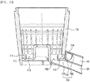
- FIGS. 26 and 28 illustrate the second pulp discharge opening 143 in the minimum opening state
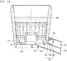
- FIGS. 27 and 29 illustrate the second pulp discharge opening 143 in the maximum opening state.
- the user is able to adjust the amount of pulp discharged outside through the first and the second pulp discharge ports 121, 141 by using the first and the second pulp discharge adjusting apparatuses 800, 700. It is particularly enabled to adjust the amounts of the pulp and the juice discharged into one single container at a variety of mixing ratios, by adjusting the amount of pulp discharge of the second pulp discharge port 141 which is at the same location as the juice discharge port 131.
Landscapes
- Life Sciences & Earth Sciences (AREA)
- Chemical & Material Sciences (AREA)
- Engineering & Computer Science (AREA)
- Food Science & Technology (AREA)
- Polymers & Plastics (AREA)
- Food-Manufacturing Devices (AREA)
- Apparatus For Making Beverages (AREA)
- Paper (AREA)
- Devices For Dispensing Beverages (AREA)
Description
- Embodiments of the present disclosure relate to a drum assembly having a pulp discharge adjusting apparatus, and a juicer comprising the same, and more particularly, to a drum assembly having a pulp discharge adjusting apparatus for adjusting an amount of pulps discharged from a drum body according to a type of a subject being extracted or a user preference, and a juicer comprising the same.
- Juicers are electronic appliances used to directly squeeze out fruit juice or vegetable juice from fruits or vegetables for drinks. A variety of juicers are introduced to help home users to conveniently extract juice from vegetables or fruits for their healthy lives.
- Generally, a juicer receives a subject being extracted (e.g., fruit or vegetable) in a drum in which an extraction screw is rotatably mounted, and crushes the subject being extracted and squeezes out juice therefrom by rotating the extraction screw with a driving portion located under the drum. After crushing and squeezing by the extraction screw, the subject being extracted is separated by an extraction net into juice and pulp, then the separated juice and pulp are expelled out through a juice discharge port and a pump discharge port, respectively.
- The technologies related to adjustment of pulp discharge or adjustment of extraction is known in the art. For example, Korean Patent Publication No.
2013-0028535 US Patent Publication No. 2007-0277682 discloses a juicer capable of adjusting an amount of juice extraction with a wetness control unit. - However, most juicers of the related technologies have limited accuracy or convenience in the adjustment of pulp discharge, or it is difficult to separate and clean the components associated with pulp discharge.
-
- Korean Patent Publication No.
2013-0028535 (March 19, 2013 -
US Patent Publication No. 2007-0277682 (December 6, 2007.12) - Exemplary embodiments of the present inventive concept overcome the above disadvantages and other disadvantages not described above. Also, the present inventive concept is not required to overcome the disadvantages described above, and an exemplary embodiment of the present inventive concept may not overcome any of the problems described above.
- Accordingly, it is a main object of the present invention to provide a method for enhancing convenience of cleaning components associated with pulp discharge, while also enhancing accuracy and convenience of adjusting pulp discharge.
- According to an exemplary embodiment, a drum assembly for a juicer is provided, in which comprises a drum body having a juice discharge port and at least one pulp discharge port, and a pulp discharge adjusting apparatus mounted on the pulp discharge port to adjust an amount of pulp discharge.
- The pulp discharge adjusting apparatus may comprise a discharge resistance exerting member installed in the pulp discharge port to exert a discharge resistance on a pulp being discharged through the pulp discharge port, and having an elastically deformable portion which is elastically deformable by pressing of the pulp being discharged, and a discharge resistance adjusting member operated by a user to adjust the discharge resistance.
- The pulp discharge adjusting apparatus may further comprise a connecting member coupled with the discharge resistance exerting member and the discharge resistance adjusting member, respectively, and guiding a movement of the discharge resistance adjusting member during adjustment of the discharge resistance.
- The discharge resistance adjusting member may be coupled with the connecting member such that the discharge resistance adjusting member is slidable between a first position of contacting an outer surface of the elastically deformable portion and a second position of being spaced from the outer surface of the elastically deformable portion.
- The connecting member is attachable to or detachable from the pulp discharge port in a state of being coupled with the discharge resistance exerting member and the discharge resistance adjusting member.
- The discharge resistance adjusting member may be disposed to be in contact with an upper region of the elastically deformable portion and is rotatably coupled with the connecting member, and the discharge resistance adjusting member may have a shape with a variable distance between a lower end of the discharge resistance adjusting member and a lower end of the elastically deformable portion according to a rotation thereof.
- The discharge resistance adjusting member may have a shape of a ring penetrated by the connecting member, and an outer circumferential surface of the discharge resistance adjusting member may comprise a plurality of flat edge surfaces at different distances from an axis of rotation.
- The discharge resistance adjusting member may comprise an operating portion rotatably coupled with the connecting member and partially exposed outside the pulp discharge port, and a contacting portion provided on an inner end of the operating portion and disposed to be in contact with the upper region of the elastically deformable portion.
- The contacting portion may be provided as a plate shape, and an outer circumferential surface of the contacting portion comprises a plurality of flat edge surfaces at different distances from an axis of rotation.
- The contacting portion may be provided as a plate shape, and an outer circumferential surface of the contacting portion is formed as a curved surface at a variable distance from an axis of rotation.
- The pulp discharge adjusting apparatus may comprise an opening/closing member for opening and closing a pulp discharge opening of the drum body, and an operating member coupled with the opening/closing member and rotatably mounted on the pulp discharge port. An opening degree of the pulp discharge opening by the opening/closing member may be adjusted according to the rotation of the operating member.
- The pulp discharge port may have a shape with an open upper side, the operating member may be disposed within the pulp discharge port, and the operating member may have a protecting protrusion provided on one side to prevent a finger from entering the pulp discharge opening.
- The drum body may comprise a first pulp discharge port in fluid communication with the first pulp discharge opening, and a second pulp discharge port in fluid communication with the second pulp discharge opening and disposed over the juice discharge port, and a first and a second pulp discharge adjusting apparatuses may be installed in the first and the second pulp discharge ports, respectively.
- The first pulp discharge adjusting apparatus may comprise a discharge resistance exerting member installed in the pulp discharge port to exert discharge resistance on a pulp being discharged through the first pulp discharge port, and having an elastically deformable portion which is elastically deformable by pressing of the pulp being discharged, and a discharge resistance adjusting member operated by a user to adjust the discharge resistance.
- The second pulp discharge adjusting apparatus may comprise an opening/closing member for opening and closing the second pulp discharge opening, and an operating member coupled with the opening/closing member and rotatably mounted on the second pulp discharge port. An opening degree of the second pulp discharge opening may be adjusted by the opening/closing member according to a rotation of the operating member.
- The above and/or other aspects of the present inventive concept will be more apparent by describing certain exemplary embodiments of the present inventive concept with reference to the accompanying drawings, in which:
-
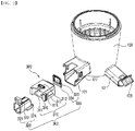
FIG. 1 is a perspective view of a drum assembly according to a first exemplary embodiment of the present invention; -
FIG. 2 is an exploded perspective view of a drum assembly according to the first exemplary embodiment; -
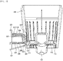
FIG. 3 is a cross sectional view of the drum assembly according to the first exemplary embodiment; -
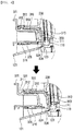
FIG. 4 is a cross sectional view provided to explain a principle of operation of the drum assembly according to the first exemplary embodiment; -
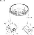
FIG. 5 is a perspective view of a drum assembly according to a second exemplary embodiment of the present invention; -
FIG. 6 is an exploded perspective view of the drum assembly according to the second exemplary embodiment; -
FIG. 7 is a cross sectional view of the drum assembly according to the second exemplary embodiment; -
FIG. 8 is a side view of a pulp discharge adjusting member provided in the drum assembly according to the second exemplary embodiment; -
FIG. 9 is a cross sectional view provided to explain a principle of operation of the drum assembly according to the second exemplary embodiment; -
FIG. 10 is a perspective view of a drum assembly according to a third exemplary embodiment of the present invention; -
FIG. 11 is an exploded perspective view of the drum assembly according to the third exemplary embodiment; -
FIG. 12 is a perspective view of a pulp discharge adjusting apparatus provided in the drum assembly according to the third exemplary embodiment; -
FIG. 13 is a view provided to explain a principle of operation of the drum assembly according to the third exemplary embodiment; -
FIG. 14 is a perspective view of a pulp discharge adjusting apparatus according to a fourth exemplary embodiment of the present invention; -
FIG. 15 is an exploded perspective view of the pulp discharge adjusting apparatus according to the fourth exemplary embodiment; -
FIG. 16 is a view provided to explain a principle of operation of the pulp discharge adjusting apparatus according to the fourth exemplary embodiment; -
FIG. 17 is a perspective view of a pulp discharge adjusting apparatus according to a fifth exemplary embodiment of the present invention; -
FIG. 18 is an exploded perspective view of the drum assembly according to the fifth exemplary embodiment; -
FIG. 19 is a view provided to explain a principle of operation of the pulp discharge adjusting apparatus according to the fifth exemplary embodiment; -
FIG. 20 is a perspective view of a drum assembly according to a sixth exemplary embodiment of the present invention; -
FIG. 21 is another perspective view of the drum assembly according to the sixth exemplary embodiment; -
FIG. 22 is a perspective view of a first pulp discharge adjusting apparatus according to the sixth exemplary embodiment; -
FIG. 23 is another perspective view of the first pulp discharge adjusting apparatus according to the sixth exemplary embodiment; -
FIG. 24 is a cross sectional view of the drum assembly according to the sixth exemplary embodiment; -
FIG. 25 is a view provided to explain a principle of operation of the first pulp discharge adjusting apparatus according to the sixth exemplary embodiment; -
FIG. 26 is a perspective view of a second pulp discharge port in closed state, according to the sixth exemplary embodiment; -
FIG. 27 is a perspective view of the second pulp discharge port in an open state, according to the sixth exemplary embodiment; -
FIG. 28 is a cross sectional view of the second pulp discharge port in a closed state, according to the sixth exemplary embodiment; and -
FIG. 29 is a cross sectional view of the second pulp discharge port in an open state, according to the sixth exemplary embodiment. - Certain exemplary embodiments of the present inventive concept will now be described in greater detail with reference to the accompanying drawings.
- Referring to
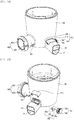
FIGS. 1 to 4 , a drum assembly according to a first exemplary embodiment will be described. - According to the first exemplary embodiment, the drum assembly includes a
drum body 100 and a pulpdischarge adjusting apparatus 300. - The
drum body 100 is a hollow cylindrical container structure having a space defined therein, and receives an extraction screw (not illustrated) therein. - The
drum body 100 includes aguide jaw 110 protruding from an inner bottom surface with a circular cross section of a predetermined diameter, afirst guide groove 111 formed on an outer side of theguide jaw 110, asecond guide groove 112 formed on an inner side of theguide jaw 110, a pulp discharge opening 123 formed on an outermost side of thefirst guide groove 111, apulp discharge port 121 for guiding pulp expelled into the pulp discharge opening 123 to outside, a juice discharge opening (not illustrated) formed on an outermost side of thesecond guide groove 112, and ajuice discharge port 131 for guiding juice expelled through the juice discharge opening to outside. - The
pulp discharge port 121 and thejuice discharge port 131, respectively in fluid communication with thepulp discharge opening 123 and the juice discharge opening (not illustrated), extend outside thedrum body 100. The pulp and the juice can be easily discharged out of thedrum body 100 through thepulp discharge port 121 and thejuice discharge port 131. - The subject being extracted is separated into juice and pulp by the rotational force while it is passed through the extraction screw. Once separated, the separated juice is moved along the
second guide groove 112, and then, discharged out of thedrum body 100 through a juice discharge opening (not illustrated) and thejuice discharge port 131. The separated pulp is moved along thesecond guide groove 111, and then, discharged out of thedrum body 100 through thepulp discharge opening 123 and thepulp discharge port 121. - Meanwhile, the
juice discharge port 131 is provided with alid 133 to open or close thejuice discharge port 131. For cleaning operation of thedrum body 100, the process can be conveniently performed by closing thejuice discharge port 131 with thelid 133 and introducing a cleansing liquid into thedrum body 100. - According to the first exemplary embodiment, the pulp
discharge adjusting apparatus 300 includes a dischargeresistance exerting member 330, a dischargeresistance adjusting member 320, and a connectingmember 310. - The discharge
resistance exerting member 330 exerts discharge resistance on the pulp as the pulp is discharged through thepulp discharge port 121. The dischargeresistance exerting member 330 may be disposed within apulp discharge port 121, for example, immediately in front of thepulp discharge opening 123. - The discharge
resistance exerting member 330 includes aninsertion hole 333 for coupling an elasticallydeformable portion 334 which is elastically deformable by the pressure of the pulp being discharged, and the connectingmember 310. As illustrated inFIG. 2 , the dischargeresistance exerting member 330 may be formed into a slender bar, and the connectingmember 310 and the dischargeresistance exerting member 330 may be coupled with each other, as an insertingportion 313 formed on an inner end of the connectingmember 310 is inserted into theinsertion hole 333. - Such coupling between the discharge
resistance exerting member 330 and the connectingmember 310 allows the pulpdischarge adjusting apparatus 300 to be attached to and detached from thepulp discharge port 121 at once. Accordingly, it is easy to attach and detach the pulpdischarge adjusting apparatus 300, and it is also easy to clean thedrum body 100 and the pulpdischarge adjusting apparatus 300. - The discharge
resistance adjusting member 320 is operated by a user to adjust the discharge resistance exerted by the dischargeresistance exerting member 330 on the discharging pulp. The dischargeresistance adjusting member 320 is slidably coupled with the connectingmember 310 so that the dischargeresistance adjusting member 320 is slid between a first position at which the dischargeresistance adjusting member 320 is contacted with an outer surface of the elasticallydeformable portion 334 of the discharge resistance exerting member 330 (seeFIG. 4 , upper half), and a second position at which the dischargeresistance adjusting member 320 is spaced from the outer surface of the elastically deformable portion 334 (seeFIG. 4 , lower half). - An adjusting
protrusion 324 is formed on an inner end of the dischargeresistance adjusting member 320. The adjustingprotrusion 324 may selectively contact the elasticallydeformable portion 334 of the dischargeresistance exerting member 330 which forms a lower side. More specifically, when the dischargeresistance adjusting member 320 is slid from the second position to the first position, the adjustingprotrusion 324 contacts the elasticallydeformable portion 334, while, on the contrary, i.e., when the dischargeresistance adjusting member 320 is slid from the first position to the second position, the adjustingprotrusion 324 is spaced away from the elasticallydeformable portion 334. - When the adjusting
protrusion 324 contacts the elasticallydeformable portion 334, the movement of the elasticallydeformable portion 334 is restricted due to the adjusting protrusion 324 (seeFIG. 4 , upper half), which accordingly increases the discharge resistance of the elasticallydeformable portion 334. - An operating
portion 321 is positioned on an upper side of the dischargeresistance adjusting member 320, and the user may control the sliding movement of the dischargeresistance adjusting member 320 with the operatingportion 321. By moving the dischargeresistance adjusting member 320 to thus bring the adjustingprotrusion 324 into contact with the elasticallydeformable portion 334, the operatingportion 321 may be received in an operatingportion groove 311 formed in the connectingmember 310. Anupper protrusion 322 is formed on the upper surface of the dischargeresistance adjusting member 320. The dischargeresistance adjusting member 320 may be fixed in the first position described above (seeFIG. 4 , lower half), as theupper protrusion 322 is inserted into anupper groove 312 formed on the upper portion of the connectingmember 310. - When the discharge
resistance adjusting member 320 is moved to the second position described above (seeFIG. 4 , lower half), the movement of the elasticallydeformable portion 334 is not restricted, which accordingly reduces the discharge resistance of the dischargeresistance exerting member 330. - The connecting
member 310 is coupled with the dischargeresistance exerting member 330 and the dischargeresistance adjusting member 320, respectively, and guides the movement (i.e., sliding) of the dischargeresistance adjusting member 320 between the first position and the second position. - The connecting
member 310 may be in the state of being coupled with the dischargeresistance exerting member 330 and the dischargeresistance adjusting member 320, when the connectingmember 310 is attached to or detached from thepulp discharge port 121. That is, the pulpdischarge adjusting apparatus 300 that includes the dischargeresistance exerting member 330, the dischargeresistance adjusting member 320 and the connectingmember 310 may be attached to or detached from thepulp discharge port 121 in an assembled state. Accordingly, it is convenient to attach and detach the pulpdischarge adjusting apparatus 300 to and from thepulp discharge port 121. - The connecting
member 310 includes alower groove 316, and the dischargeresistance adjusting member 320 includes alower protrusion 326 to be inserted into thelower groove 316. When the dischargeresistance adjusting member 320 is moved from the first position to the second position, thelower protrusion 326 inserted into thelower groove 316 can prevent the separation of the dischargeresistance adjusting member 320 from the connectingmember 310. - The connecting
member 310 includes a mountingportion 315 and a side protrusion 317 on both sides for the mounting to thepulp discharge port 121. Thepulp discharge port 121 includes a recess on a leading end for coupling with the mountingportion 315, and a fixinggroove 127 for coupling with the side protrusion 317. The coupling of the side protrusion 317 with the fixinggroove 127 allows the pulpdischarge adjusting apparatus 300 to be stably fixed to thepulp discharge port 121. - A drum assembly according to a second exemplary embodiment will be explained below with reference to
FIGS. 5 to 9 . - According to the second exemplary embodiment, the drum assembly includes a
drum body 100, and a pulpdischarge adjusting apparatus 400. - As in the case of the
drum body 100 according to the first exemplary embodiment, thedrum body 100 according to the second exemplary embodiment includes apulp discharge port 121 and ajuice discharge port 131. As illustrated inFIGS. 5 and6 , thepulp discharge port 121 according to the second exemplary embodiment is formed into an approximately cylindrical shape, and includes asupport 128 formed inside, and a fixingprotrusion 125 formed outside. - According to the second exemplary embodiment, the pulp
discharge adjusting apparatus 400 includes a dischargeresistance exerting member 430, a connectingportion 440 and a dischargeresistance adjusting member 420, and a mountingmember 410. - The discharge
resistance exerting member 430 exerts discharge resistance on the pulp discharged through thepulp discharge port 121, and may be disposed to face thepulp discharge opening 123, for example. - The discharge
resistance exerting member 430 includes an elasticallydeformable portion 434, and aninsertion hole 433 for coupling of the elasticallydeformable portion 434 and the connectingmember 440. For example, the dischargeresistance exerting member 430 may be formed into a thin film. The connectingmember 440 and the dischargeresistance exerting member 430 may be coupled with each other, as an insertingportion 443 of the connectingmember 440 is inserted into theinsertion hole 433. - The connecting
member 440 includes the insertingportion 443, and ashaft portion 444 extending from an outer surface of the insertingportion 443. The connectingmember 440 and the dischargeresistance exerting member 430 may be coupled with each other, as the insertingportion 443 of the connectingmember 440 is inserted into theinsertion hole 433. Theshaft portion 444 has a cylindrical shape and has acoupling hole 442 formed on an upper surface thereof. - The discharge
resistance adjusting member 420 is provided to adjust the discharge resistance of the dischargeresistance exerting member 430, and is operated by the user to adjust the discharge resistance. - The discharge
resistance adjusting member 420 has ashaft insertion hole 423 on a center, to which theshaft portion 444 of the connectingmember 440 is inserted. As illustrated inFIG. 7 , the dischargeresistance adjusting member 420 is rotatably coupled with the connectingmember 440 to be rotated about theshaft portion 440, and is so disposed that the dischargeresistance adjusting member 420 is contacted, in the coupled state, to an upper region of the elasticallydeformable portion 434 of the dischargeresistance exerting member 430. - The discharge
resistance adjusting member 420 is formed into an approximately square ring shape. As an example, an outercircumferential surface 424 of the dischargeresistance adjusting member 420 may be configured with a plurality of flat edge surfaces at different distances from an axis of rotation A. - Referring to an example of
FIG. 8 , the outercircumferential surface 424 of the dischargeresistance adjusting member 420 may include four flat edge surfaces which are at different distances from the axis of rotation A. - In
FIG. 8 , the reference symbol d1 denotes distances between the axis of rotation A and respective flat edge surfaces, and inFIG. 9 , the reference symbol d2 denotes a distance between the axis of ration A and a lower end of the elasticallydeformable portion 434, in which d2 is preferably larger than d1. InFIG. 9 , reference symbols x1, x2, x3, x4 denote differences between d1 and d2 for each of the four flat edge surfaces, which are perpendicular widths of the elastically deformable area of the elasticallydeformable portion 434 which is not in contact with the dischargeresistance adjusting member 420. - Referring to
FIG. 9 , as the dischargeresistance adjusting member 420 is rotated, the distances x1, x2, x3, x4 vary between the lower ends (i.e., one of the flat edge surfaces) of the dischargeresistance adjusting member 420 and the lower end of the elasticallydeformable portion 434. These variations in the distances x1, x2, x3, x4 indicate that the discharge resistance of the dischargeresistance exerting member 430 varies, and increase in these distances x1, x2, x3, x4 indicates that the discharge resistance of the dischargeresistance exerting member 430 is decreased. In the example ofFIG. 9 , it is also understandable that the adjustment of the discharge resistance can be performed in four stages. - As described, the pulp discharge resistance can be set to any of a plurality of conditions based on rotational operation of the discharge
resistance adjusting member 420. Accordingly, it is possible to accomplish the condition for extraction that is suitable for the type of the subject being extracted or for user preference. - As exemplified above, the discharge
resistance adjusting member 420 may have four flat edge surfaces corresponding to four discharge resistances, but exemplary embodiments are not limited thereto. Accordingly, in alternative embodiments, three, five, six or various other number of flat edge surfaces may be employed. Further, as exemplified in the present embodiment, the dischargeresistance adjusting member 420 may have a plurality of flat edge surfaces corresponding to a plurality of discharge resistances on the outercircumferential surface 424 of the dischargeresistance adjusting member 420, but exemplary embodiments are not limited thereto. Accordingly, in alternative embodiments, the flat edge surfaces may be modified to curved surfaces. - The mounting
member 410 is a component provided to fix the pulpdischarge adjusting apparatus 400 with respect to thepulp discharge port 121. As illustrated inFIG. 7 , the mountingmember 410 has acoupling protrusion 413 formed on an inner surface to be inserted into thecoupling hole 442 of the connectingmember 440 described above. The mountingmember 410 and the connectingmember 440 may be connected with each other by the coupling of thecoupling protrusion 413 and thecoupling hole 442. - The mounting
member 410 has a fixingsegment 415 on an outer surface to be coupled with the fixingprotrusion 125 of thepulp discharge port 121. The mountingmember 410 can be fixed to thepulp discharge port 121 by the coupling of the fixingprotrusion 125 and the fixingsegment 415. - With the connecting
member 440, the dischargeresistance exerting member 430, the dischargeresistance adjusting member 420, and the mountingmember 410 may be constructed as one single assembly. Accordingly, the pulpdischarge adjusting apparatus 400, which is connected with therespective components member 440 as one single assembly, may be attached to, or detached from thepulp discharge port 121. This means that attaching or detaching the pulpdischarge adjusting apparatus 400 can each be performed by only one operation. Accordingly, attaching and detaching the pulpdischarge adjusting apparatus 400 is very convenient to perform, and convenience of cleaning thedrum assembly 100 is also enhanced. -
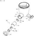
FIGS. 10 to 13 illustrate a drum assembly according to a third exemplary embodiment, andFIGS. 14 to 16 illustrate a drum assembly according to a fourth exemplary embodiment. - The drum assembly of the third exemplar embodiment and the drum assembly of the fourth exemplary embodiment have only difference in the configurations of the discharge
resistance adjusting members portions 523, 624. Hereinbelow, the drum assemblies according to the third and the fourth exemplary embodiments will be explained together. - The drum assembly according to the third exemplary embodiment includes a
drum body 100 and a pulpdischarge adjusting apparatus 500. Likewise, the drum assembly according to the fourth exemplary embodiment includes adrum body 100 and a pulpdischarge adjusting apparatus 600. - According to the third and the fourth exemplary embodiments, the
drum body 100 has the same structure as thedrum body 100 according to the second exemplary embodiment described above. Accordingly, thedrum body 100 will not be described in detail below. - According to the third exemplary embodiment, the pulp
discharge adjusting apparatus 500 includes a dischargeresistance exerting member 530, a connectingmember 510, a dischargeresistance adjusting member 520 and a mountingmember 515. - Similarly, the pulp
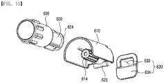
discharge adjusting apparatus 600 according to the fourth exemplar embodiment includes a dischargeresistance exerting member 630, a connectingmember 610, a dischargeresistance adjusting member 620, and a mounting member (not illustrated). - Each of the discharge
resistance exerting members resistance exerting member 420 according to the second exemplary embodiment. Accordingly, the dischargeresistance exerting members deformable portion insertion hole - Each of the connecting
members portion 623 for coupling with the insertinghole shaft portion 614 for coupling with the dischargeresistance adjusting member - Each of the discharge
resistance adjusting members resistance exerting member resistance adjusting member - Each of the discharge
resistance adjusting members portion portion portion FIG. 10 , the operatingportion pulp discharge port 121 for the user's convenience of handling the same. Meanwhile, the contactingportion deformable portion - Referring to
FIGS. 11 and13 , the contactingportion 524 according to the third exemplary embodiment is provided as an approximately plate form. An outer circumferential surface of the contactingportion 524 includes a plurality of flat edge surfaces at different distances d3 from the axis of rotation A. InFIG. 13 , a reference symbol d4 refers to a distance between the axis of rotation A and a lower end of the elasticallydeformable portion 534. - As illustrated in
FIG. 13 , according to the rotation of the dischargeresistance adjusting member 520, the distance x1, x2, x3, x4 between the lower end of the contactingportion 524 and the lower end of the elasticallydeformable portion 534 may vary into four stages. As the distance x1, x2, x3, x4 varies, the discharge resistance of the elasticallydeformable portion 534 varies. Specifically, an increase in the distance x1, x2, x3, x4 leads into a decrease in the discharge resistance, while a decrease in the distance x1, x2, x3, x4 leads into an increase in the discharge resistance. As exemplified in the third exemplary embodiment, the four flat edge surfaces may be provided, but it is of course possible that the number of the flat edge surfaces can be modified. - Referring to
FIGS. 14 and16 , the contactingportion 624 according to the fourth exemplary embodiment is provided as an approximately plate shape. An outer circumferential surface of the contactingportion 624 is formed as a curved surface which has a variable distance from the axis of rotation A. - As illustrated in
FIG. 16 , the rotation of the dischargeresistance adjusting member 620 allows a distance x1, x2, x3 between the lower end of the contactingportion 624 and the lower end of the elasticallydeformable portion 634 to be varied into three stages. As the distance x1, x2, x3 varies, the discharge resistance of the elasticallydeformable portion 534 varies. As exemplified in the fourth exemplary embodiment, the distance x1, x2, x3 may be varied into three stages, but exemplary embodiments are not limited thereto. Accordingly, the number of variable stages may be varied, according to modifications in the design of the outer circumferential surface of the contactingportion 624. - The mounting
members 515 is each provided to fix the pulpdischarge adjusting apparatus pulp discharge port 121. The mountingmember 515 may be coupled with the connectingmember member protrusion 125 of thepulp discharge port 121 is provided on an inner side surface of the mountingmember 515. - Similarly to the pulp
discharge adjusting apparatuses discharge adjusting apparatuses pulp discharge port 121 as a one single assembly state. This means that attaching and detaching the pulpdischarge adjusting apparatuses drum assembly 100 can be enhanced accordingly. - The drum assembly according to the fifth exemplary embodiment will be explained with reference to
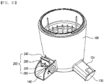
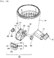
FIGS. 17 to 19 . - According to the fifth exemplary embodiment, the drum assembly includes a
drum body 100 and a pulpdischarge adjusting apparatus 200. - The
drum body 100 has an approximately cylindrical container structure in which an extraction screw (not illustrated) is received. Thedrum body 100 includes ajuice discharge port 131 and apulp discharge port 140. Thejuice discharge port 131 has alid 133 to open and close the same. Thepulp discharge port 140 is in fluid communication with thepulp discharge opening 120. Thepulp discharge port 140 has a shape with an open upper side. - The pulp
discharge adjusting apparatus 200 includes an opening/closingmember 260 to open and close thepulp discharge opening 120, an operating member coupled with the opening/closingmember 260 and rotatably engaged with thepulp discharge port 140, and a pair ofcoupling members 290 to couple the operatingmember 240 with thepulp discharge port 140. - The opening/closing
member 260 is received in thepulp discharge port 140, and is disposed to face with thepulp discharge opening 120. The opening/closingmember 260 includes a connectingportion 262 connected with the operatingmember 240, and an opening/closing portion 264 for opening and closing thepulp discharge opening 120. A plurality ofprotrusions 266 are formed on the side surface of the connectingportion 262. When the opening/closingmember 260 is rotated, the angle of rotation of the opening/closingmember 260 may be set to a desired angle by the interaction between the plurality ofprotrusions 266 and lockingjaws 144 provided on thepulp discharge port 140. The opening/closing portion 264 may be provided as a curved form, and thepulp discharge opening 120 may be provided as a curved form to correspond to the same. - The operating
member 240 is received in thepulp discharge port 140 and has an approximately rectangular shape. The operatingmember 240 includes acoupling portion 220 coupled with acoupling member 290, and a protectingprotrusion 280 provided on an outer surface of the operatingmember 240. The protectingprotrusion 280 is provided to prevent a user's finger from entering the pulp discharge opening 120 while the opening/closingmember 260 is opening thepulp discharge opening 120. In an exemplary embodiment in which an upper side of thepulp discharge port 140 is open, it is particularly necessary to prevent the user's finger from touching the extraction screw. - The
coupling member 290 is coupled with thepulp discharge port 140 through acoupling hole 142. The operatingmember 240 described above is rotatably mounted to thepulp discharge port 140 by being coupled with a pair ofcoupling members 290. A lockingjaw 292 is formed on thecoupling member 290 and there is a lockingprotrusion 146 in thecoupling hole 142 for interacting with the lockingjaw 292. When the opening/closingmember 260 is rotated, the lockingjaws 292 are locked in both ends of the lockingprotrusion 146, thus limiting the range of rotatable movement of the opening/closingmember 260. Accordingly, the opening/closingmember 260 can be rotated within a predetermined angle range by the lockingprotrusion 146. - As illustrated in
FIG. 19 , the opening degree of the pulp discharge opening 120 by the opening/closingmember 260 can be adjusted according to the rotation of the operatingmember 240, and accordingly, an amount of pulp discharged from the pulp discharge opening 120 can be adjusted. - The
pulp discharge opening 120 has a minimum opening degree when the opening/closingmember 260 is in the position ofFIG. 19(a) , while thepulp discharge opening 120 has a maximum opening degree when the opening/closingmember 260 is in the position ofFIG. 19(c) . Further, the opening/closingmember 260 may be at one or more intermediate opening positions as illustrated inFIG. 19(b) . Accordingly, it is enabled to adjust the amount of discharge pulp from the pulp discharge opening 120 into three or more stages by rotating the opening/closingmember 260 with the operatingmember 240. - The drum assembly according to the sixth exemplary embodiment will be explained with reference to
FIGS. 20 to 29 . - According to the sixth exemplary embodiment, the drum assembly includes a
drum body 100, a first pulpdischarge adjusting apparatus 800, and a second pulpdischarge adjusting apparatus 700. - The
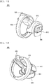
drum body 100 includes ajuice discharge port 131, a firstpulp discharge port 121, and a secondpulp discharge port 141. As illustrated inFIG. 20 , the secondpulp discharge port 141 is disposed immediately over thejuice discharge port 131. Accordingly, both the juice discharged from thejuice discharge port 131 and the pulp discharged from the secondpulp discharge port 141 may be discharged simultaneously into one single container. As illustrated inFIG. 21 , a mounting hole is formed on an inner end of the secondpulp discharge port 141 to mount the first pulpdischarge adjusting apparatus 700. - Further, the
drum body 100 includes a guidingjaw 110 protruding from an inner bottom surface in a circular cross section of a predetermined diameter, afirst guide groove 111 formed outside the guidingjaw 110, asecond guide groove 112 formed within the guidingjaw 110, a firstpulp discharge opening 123 connecting thefirst guide groove 111 with the firstpulp discharge port 121, a secondpulp discharge opening 143 connecting thefirst guide groove 111 with the secondpulp discharge port 141, and ajuice discharge opening 133 connecting thesecond guide groove 112 with thejuice discharge port 131. - The juice separated from the subject being extracted within the
drum body 100 may be discharged through thesecond guide groove 112, thejuice discharge opening 133 and thejuice discharge port 131. Meanwhile, the pulp separated from the subject being extracted within thedrum body 100 may be discharged outside through thefirst guide groove 111, the firstpulp discharge opening 123 and the firstpulp discharge port 121, or discharged outside through thefirst guide groove 111, the secondpulp discharge opening 143 and the secondpulp discharge port 141. The amount of the pulp discharged outside through the firstpulp discharge port 121 may be adjusted by the first pulpdischarge adjusting apparatus 800, and the amount of the pulp discharged outside through the secondpulp discharge port 141 may be adjusted by the second pulpdischarge adjusting apparatus 700. - According to the sixth exemplary embodiment, the first pulp
discharge adjusting apparatus 800 includes a dischargeresistance exerting member 834, a connectingmember 810 and a dischargeresistance operating member 825. - The discharge
resistance exerting member 834 is provided to exert discharge resistance on the pulp being discharged through the firstpulp discharge opening 123, and may have the same structure as the dischargeresistance exerting member 430 according to the second exemplary embodiment described above (seeFIG. 6 ). - The connecting
member 810 connects the dischargeresistance exerting member 834 with the dischargeresistance operating member 825, and rotatably supports the dischargeresistance operating member 825. An insertingportion 813 for insertion into the dischargeresistance exerting member 834 is provided on an inner end of the connectingmember 810. - The discharge
resistance operating member 825 is rotatably mounted on the firstpulp discharge port 121. An operatingprotrusion 826 is provided on an outer end of the dischargeresistance operating member 825 for convenience of the user. A contactingportion 824 is provided on an inner end of the dischargeresistance operating member 825 in contact with the dischargeresistance exerting member 834. The contactingportion 834 may have the same shape as the contactingportion 524 illustrated and described above with reference to the exemplary embodiment ofFIG. 13 , or as the contactingportion 624 illustrated and described above with reference to the exemplary embodiment ofFIG. 16 . - As illustrated in
FIG. 25 , a distance x1, x2, x3 between a lower end of the contactingportion 824 and a lower end of the dischargeresistance exerting member 834 may vary, as the dischargeresistance operating member 825 is rotated. According to an exemplary embodiment, the distance x1, x2, x3 may be varied into three stages, and accordingly, the discharge resistance exerted by the dischargeresistance exerting member 834 may be varied into three stages. As such, it is possible to adjust an amount of pulp discharged from the firstpulp discharge port 121 by adjusting the discharge resistance. InFIG. 25 , a reference symbol d6 denotes a distance between an axis of rotation A and the lower end of the dischargeresistance exerting member 834, and d5 denotes a distance between the axis of rotation A and the lower end of the contactingportion 824. - According to the sixth exemplary embodiment, the second pulp
discharge adjusting apparatus 700 includes an opening/closingmember 730, an operatingmember 740 and acover member 710. - The opening/closing
member 730 is provided to open and close the secondpulp discharge opening 143 and is so disposed as to face the secondpulp discharge opening 143. The opening/closingmember 730 includes acover portion 731 and a pair ofside portions 732. One of the pair ofside portions 733 may have arotation restricting protrusion 733 to set a range of rotation of the opening/closingmember 730. - The opening/closing
member 730 is rotatably mounted on the secondpulp discharge port 141, and shielded by thecover member 710 from exposure to outside. Thecover member 710 may be formed of a transparent material so that the opening/closingmember 730 is seen through from outside. - The operating
member 740 is provided to rotatably operate the opening/closingmember 730, and is connected to one of the pair ofside portions 732. The operatingmember 740 includes abody portion 745 and a detectingprotrusion 746 formed on its outer circumference. Thebody portion 745 may have a shape of a disk. The user can perceive the angle of rotation of the opening/closingmember 730 from the location of a detectingprotrusion 746. The detectingprotrusion 746 may be omitted, whencover member 710 is formed of a transparent material. - As the operating
member 740 is rotated by the operating of the user, the opening degree of the second pulp discharge opening 143 can be adjusted by the opening/closingmember 730, and accordingly, the amount of pulp discharged outside from the secondpulp discharge port 141 can be adjusted. -
FIGS. 26 and28 illustrate the second pulp discharge opening 143 in the minimum opening state, andFIGS. 27 and29 illustrate the second pulp discharge opening 143 in the maximum opening state. - The user is able to adjust the amount of pulp discharged outside through the first and the second
pulp discharge ports discharge adjusting apparatuses pulp discharge port 141 which is at the same location as thejuice discharge port 131.
Claims (15)
- A drum assembly for a juicer, comprising:a drum body having a juice discharge port and at least one pulp discharge port; anda pulp discharge adjusting apparatus mounted on the pulp discharge port to adjust an amount of pulp discharge.
- The drum assembly for a juicer of claim 1, wherein the pulp discharge adjusting apparatus comprises:a discharge resistance exerting member installed in the pulp discharge port to exert a discharge resistance on a pulp being discharged through the pulp discharge port, and having an elastically deformable portion which is elastically deformable by pressing of the pulp being discharged; anda discharge resistance adjusting member operated by a user to adjust the discharge resistance.
- The drum assembly for a juicer of claim 2, wherein the pulp discharge adjusting apparatus further comprises a connecting member coupled with the discharge resistance exerting member and the discharge resistance adjusting member, respectively, and guiding a movement of the discharge resistance adjusting member during adjustment of the discharge resistance.
- The drum assembly for a juicer of claim 3, wherein the discharge resistance adjusting member is coupled with the connecting member such that the discharge resistance adjusting member is slidable between a first position of contacting an outer surface of the elastically deformable portion and a second position of being spaced from the outer surface of the elastically deformable portion.
- The drum assembly for a juicer of claim 3, wherein the connecting member is attachable to or detachable from the pulp discharge port in a state of being coupled with the discharge resistance exerting member and the discharge resistance adjusting member.
- The drum assembly for a juicer of claim 3, wherein the discharge resistance adjusting member is disposed to be in contact with an upper region of the elastically deformable portion and is rotatably coupled with the connecting member, and
the discharge resistance adjusting member has a shape with a variable distance between a lower end of the discharge resistance adjusting member and a lower end of the elastically deformable portion according to a rotation thereof. - The drum assembly for a juicer of claim 6, wherein the discharge resistance adjusting member has a shape of a ring penetrated by the connecting member, and an outer circumferential surface of the discharge resistance adjusting member comprises a plurality of flat edge surfaces at different distances from an axis of rotation.
- The drum assembly for a juicer of claim 6, wherein the discharge resistance adjusting member comprises:an operating portion rotatably coupled with the connecting member and partially exposed outside the pulp discharge port; anda contacting portion provided on an inner end of the operating portion and disposed to be in contact with the upper region of the elastically deformable portion.
- The drum assembly for a juicer of claim 8, wherein the contacting portion is provided as a plate shape, and an outer circumferential surface of the contacting portion comprises a plurality of flat edge surfaces at different distances from an axis of rotation.
- The drum assembly for a juicer of claim 8, wherein the contacting portion is provided as a plate shape, and an outer circumferential surface of the contacting portion is formed as a curved surface at a variable distance from an axis of rotation.
- The drum assembly for a juicer of claim 1, wherein the pulp discharge adjusting apparatus comprises:an opening/closing member for opening and closing a pulp discharge opening of the drum body; andan operating member coupled with the opening/closing member and rotatably mounted on the pulp discharge port,wherein an opening degree of the pulp discharge opening by the opening/closing member is adjusted according to the rotation of the operating member.
- The drum assembly for a juicer of claim 1, wherein the pulp discharge port has a shape with an open upper side,
the operating member is disposed within the pulp discharge port, and
the operating member has a protecting protrusion provided on one side to prevent a finger from entering the pulp discharge opening. - The drum assembly for a juicer of claim 1, wherein the drum body has a first pulp discharge port in fluid communication with the first pulp discharge opening, and a second pulp discharge port in fluid communication with the second pulp discharge opening and disposed over the juice discharge port, and
a first and a second pulp discharge adjusting apparatuses are installed in the first and the second pulp discharge ports, respectively. - The drum assembly for a juicer of claim 13, wherein the first pulp discharge adjusting apparatus comprises:a discharge resistance exerting member installed in the pulp discharge port to exert discharge resistance on a pulp being discharged through the first pulp discharge port, and having an elastically deformable portion which is elastically deformable by pressing of the pulp being discharged; anda discharge resistance adjusting member operated by a user to adjust the discharge resistance.
- The drum assembly for a juicer of claim 13, wherein the second pulp discharge adjusting apparatus comprises:an opening/closing member for opening and closing the second pulp discharge opening; andan operating member coupled with the opening/closing member and rotatably mounted on the second pulp discharge port,wherein an opening degree of the second pulp discharge opening is adjusted by the opening/closing member, according to a rotation of the operating member.
Applications Claiming Priority (4)
| Application Number | Priority Date | Filing Date | Title |
|---|---|---|---|
| KR1020140097191A KR102242558B1 (en) | 2014-07-30 | 2014-07-30 | Packing structure that can control flow resistance and a juicer comprising thereof |
| KR1020140103724A KR102291028B1 (en) | 2014-08-11 | 2014-08-11 | A juice extracting screw assembly having a pulp control unit and a juicer having the same |
| KR1020150007397A KR102358627B1 (en) | 2015-01-15 | 2015-01-15 | Drum assembly and a juicer comprising the same |
| PCT/KR2015/006889 WO2016017949A1 (en) | 2014-07-30 | 2015-07-03 | Drum assembly having pulp discharge control device, and juicer including same |
Publications (3)
| Publication Number | Publication Date |
|---|---|
| EP3175743A1 true EP3175743A1 (en) | 2017-06-07 |
| EP3175743A4 EP3175743A4 (en) | 2018-03-21 |
| EP3175743B1 EP3175743B1 (en) | 2020-05-27 |
Family
ID=55217786
Family Applications (1)
| Application Number | Title | Priority Date | Filing Date |
|---|---|---|---|
| EP15827591.7A Active EP3175743B1 (en) | 2014-07-30 | 2015-07-03 | Drum assembly having pulp discharge control device, and juicer including same |
Country Status (5)
| Country | Link |
|---|---|
| EP (1) | EP3175743B1 (en) |
| JP (1) | JP6363295B2 (en) |
| CN (2) | CN105310456B (en) |
| TW (1) | TWI689259B (en) |
| WO (1) | WO2016017949A1 (en) |
Families Citing this family (6)
| Publication number | Priority date | Publication date | Assignee | Title |
|---|---|---|---|---|
| JP6363295B2 (en) * | 2014-07-30 | 2018-07-25 | コーウェイ株式会社Coway Co., Ltd. | Drum assembly with pulp discharge control device and juicer including the same |
| CN109567547B (en) * | 2017-09-28 | 2021-05-04 | 广东美的生活电器制造有限公司 | Food processing cup and food processor |
| US11786065B2 (en) | 2018-02-06 | 2023-10-17 | Guangdong Midea Consumer Electric Manufacturing Co., Ltd. | Food processor |
| EP3586700A1 (en) * | 2018-06-25 | 2020-01-01 | Koninklijke Philips N.V. | A juicer and a juicing method |
| TWM574887U (en) * | 2018-11-13 | 2019-03-01 | 連錦瑞 | Multifunctional juice strainer structure of juice extracting device |
| KR102295717B1 (en) * | 2020-03-26 | 2021-08-27 | 유광형 | A Multi-Purpose Manufacturing Device |
Family Cites Families (13)
| Publication number | Priority date | Publication date | Assignee | Title |
|---|---|---|---|---|
| JPS5935142Y2 (en) * | 1980-05-31 | 1984-09-28 | 東芝テック株式会社 | cooking machine |
| US4363265A (en) * | 1980-05-31 | 1982-12-14 | Tokyo Electric Co., Ltd. | Adjustable pulp outlet for juice extractor |
| KR100638372B1 (en) * | 2005-02-01 | 2006-10-25 | 김영기 | Food waste treatment device |
| JP4063836B2 (en) * | 2005-02-01 | 2008-03-19 | キ キム ヤン | 厨 芥 Processing device |
| KR100793852B1 (en) * | 2005-03-21 | 2008-01-11 | 김영기 | Juice Juice |
| KR20080090220A (en) * | 2007-04-04 | 2008-10-08 | (주)현대가전업 | Ball type discharge device of electric mixer |
| CN102595981B (en) * | 2010-09-17 | 2015-01-07 | 金煐麒 | Juice machine with the function of making thick juice |
| KR101871330B1 (en) * | 2011-10-19 | 2018-06-26 | 코웨이 주식회사 | Screw assembly having housing and outlet of taper structure including juicer the same |
| FR2997279B1 (en) * | 2012-10-30 | 2017-09-15 | Seb Sa | CULINARY PREPARATION ELECTRICAL APPLIANCE COMPRISING A PRESSING SCREW AND AT LEAST ONE FILTER |
| CN203088678U (en) * | 2013-03-14 | 2013-07-31 | 宁波凯普电子有限公司 | Juicing device with adjustable dreg-discharging speed |
| CN203555515U (en) * | 2013-11-22 | 2014-04-23 | 宁波凯普电子有限公司 | Juicer with adjustable horizontal outlet |
| CN203693231U (en) * | 2014-02-18 | 2014-07-09 | 宁波凯普电子有限公司 | Juicer with cleaning device |
| JP6363295B2 (en) * | 2014-07-30 | 2018-07-25 | コーウェイ株式会社Coway Co., Ltd. | Drum assembly with pulp discharge control device and juicer including the same |
-
2015
- 2015-07-03 JP JP2017520850A patent/JP6363295B2/en active Active
- 2015-07-03 EP EP15827591.7A patent/EP3175743B1/en active Active
- 2015-07-03 WO PCT/KR2015/006889 patent/WO2016017949A1/en not_active Ceased
- 2015-07-29 TW TW104124523A patent/TWI689259B/en not_active IP Right Cessation
- 2015-07-30 CN CN201510459059.1A patent/CN105310456B/en active Active
- 2015-07-30 CN CN201520565295.7U patent/CN205053704U/en not_active Expired - Lifetime
Also Published As
| Publication number | Publication date |
|---|---|
| JP2017520379A (en) | 2017-07-27 |
| TWI689259B (en) | 2020-04-01 |
| EP3175743B1 (en) | 2020-05-27 |
| JP6363295B2 (en) | 2018-07-25 |
| WO2016017949A1 (en) | 2016-02-04 |
| CN105310456A (en) | 2016-02-10 |
| CN205053704U (en) | 2016-03-02 |
| EP3175743A4 (en) | 2018-03-21 |
| TW201611735A (en) | 2016-04-01 |
| CN105310456B (en) | 2019-04-26 |
Similar Documents
| Publication | Publication Date | Title |
|---|---|---|
| EP3175743B1 (en) | Drum assembly having pulp discharge control device, and juicer including same | |
| US9113740B2 (en) | Multi-purpose juicer | |
| US7481155B2 (en) | Juice extractor | |
| EP2974627B1 (en) | Apparatus for extracting juice and pulp from fruit or vegetables | |
| US20160278574A1 (en) | Detachable food griddle | |
| EP3178355B1 (en) | Juice extraction apparatus including solid net, and juicer including same | |
| RU2649488C1 (en) | Device for spiral-cutting of hard material | |
| US20140102574A1 (en) | Water valve suitable for use with a bathtub | |
| CA2987609A1 (en) | Grinder attachment for blender system | |
| US9173524B2 (en) | Special pedestal for food processor | |
| JP2014221184A (en) | Rotating grounding unit and juicer having the same | |
| CN105725714B (en) | Drip stop attachment for food processing equipment | |
| JP2017522096A (en) | Juicer juice module | |
| KR20150113427A (en) | Portable coffee extractor | |
| KR20170140047A (en) | Cooking device having glass container | |
| US11045051B2 (en) | Blade seat assembly, blending cup assembly, and food processor | |
| CN107752809B (en) | Blade holder subassembly, stirring cup subassembly and food processor | |
| KR20170028131A (en) | Drum assembly having pulp dicharge adjusting apparatus and juicer including the same | |
| KR20160066864A (en) | Juicer | |
| US11484154B2 (en) | Multifunctional food processor | |
| KR20160019244A (en) | A juice extracting screw assembly having a pulp control unit and a juicer having the same | |
| CN209391783U (en) | Cup cover assembly and food processor | |
| CN209678251U (en) | Blanking device and proportioning machine | |
| KR20150020868A (en) | A juice extracting screw assembly and a juicer having the same | |
| CN209202941U (en) | food processor |
Legal Events
| Date | Code | Title | Description |
|---|---|---|---|
| STAA | Information on the status of an ep patent application or granted ep patent |
Free format text: STATUS: THE INTERNATIONAL PUBLICATION HAS BEEN MADE |
|
| 17P | Request for examination filed |
Effective date: 20161111 |
|
| AK | Designated contracting states |
Kind code of ref document: A1 Designated state(s): AL AT BE BG CH CY CZ DE DK EE ES FI FR GB GR HR HU IE IS IT LI LT LU LV MC MK MT NL NO PL PT RO RS SE SI SK SM TR |
|
| AX | Request for extension of the european patent |
Extension state: BA ME |
|
| PUAI | Public reference made under article 153(3) epc to a published international application that has entered the european phase |
Free format text: ORIGINAL CODE: 0009012 |
|
| STAA | Information on the status of an ep patent application or granted ep patent |
Free format text: STATUS: REQUEST FOR EXAMINATION WAS MADE |
|
| DAV | Request for validation of the european patent (deleted) | ||
| DAX | Request for extension of the european patent (deleted) | ||
| A4 | Supplementary search report drawn up and despatched |
Effective date: 20180216 |
|
| RIC1 | Information provided on ipc code assigned before grant |
Ipc: A23N 1/00 20060101ALI20180212BHEP Ipc: A47J 19/00 20060101AFI20180212BHEP |
|
| STAA | Information on the status of an ep patent application or granted ep patent |
Free format text: STATUS: EXAMINATION IS IN PROGRESS |
|
| 17Q | First examination report despatched |
Effective date: 20190218 |
|
| GRAP | Despatch of communication of intention to grant a patent |
Free format text: ORIGINAL CODE: EPIDOSNIGR1 |
|
| STAA | Information on the status of an ep patent application or granted ep patent |
Free format text: STATUS: GRANT OF PATENT IS INTENDED |
|
| INTG | Intention to grant announced |
Effective date: 20200109 |
|
| GRAS | Grant fee paid |
Free format text: ORIGINAL CODE: EPIDOSNIGR3 |
|
| GRAA | (expected) grant |
Free format text: ORIGINAL CODE: 0009210 |
|
| STAA | Information on the status of an ep patent application or granted ep patent |
Free format text: STATUS: THE PATENT HAS BEEN GRANTED |
|
| AK | Designated contracting states |
Kind code of ref document: B1 Designated state(s): AL AT BE BG CH CY CZ DE DK EE ES FI FR GB GR HR HU IE IS IT LI LT LU LV MC MK MT NL NO PL PT RO RS SE SI SK SM TR |
|
| REG | Reference to a national code |
Ref country code: GB Ref legal event code: FG4D |
|
| REG | Reference to a national code |
Ref country code: CH Ref legal event code: EP |
|
| REG | Reference to a national code |
Ref country code: AT Ref legal event code: REF Ref document number: 1273623 Country of ref document: AT Kind code of ref document: T Effective date: 20200615 |
|
| REG | Reference to a national code |
Ref country code: DE Ref legal event code: R096 Ref document number: 602015053505 Country of ref document: DE |
|
| REG | Reference to a national code |
Ref country code: LT Ref legal event code: MG4D |
|
| PG25 | Lapsed in a contracting state [announced via postgrant information from national office to epo] |
Ref country code: GR Free format text: LAPSE BECAUSE OF FAILURE TO SUBMIT A TRANSLATION OF THE DESCRIPTION OR TO PAY THE FEE WITHIN THE PRESCRIBED TIME-LIMIT Effective date: 20200828 Ref country code: NO Free format text: LAPSE BECAUSE OF FAILURE TO SUBMIT A TRANSLATION OF THE DESCRIPTION OR TO PAY THE FEE WITHIN THE PRESCRIBED TIME-LIMIT Effective date: 20200827 Ref country code: LT Free format text: LAPSE BECAUSE OF FAILURE TO SUBMIT A TRANSLATION OF THE DESCRIPTION OR TO PAY THE FEE WITHIN THE PRESCRIBED TIME-LIMIT Effective date: 20200527 Ref country code: PT Free format text: LAPSE BECAUSE OF FAILURE TO SUBMIT A TRANSLATION OF THE DESCRIPTION OR TO PAY THE FEE WITHIN THE PRESCRIBED TIME-LIMIT Effective date: 20200928 Ref country code: SE Free format text: LAPSE BECAUSE OF FAILURE TO SUBMIT A TRANSLATION OF THE DESCRIPTION OR TO PAY THE FEE WITHIN THE PRESCRIBED TIME-LIMIT Effective date: 20200527 Ref country code: IS Free format text: LAPSE BECAUSE OF FAILURE TO SUBMIT A TRANSLATION OF THE DESCRIPTION OR TO PAY THE FEE WITHIN THE PRESCRIBED TIME-LIMIT Effective date: 20200927 Ref country code: FI Free format text: LAPSE BECAUSE OF FAILURE TO SUBMIT A TRANSLATION OF THE DESCRIPTION OR TO PAY THE FEE WITHIN THE PRESCRIBED TIME-LIMIT Effective date: 20200527 |
|
| REG | Reference to a national code |
Ref country code: NL Ref legal event code: MP Effective date: 20200527 |
|
| PG25 | Lapsed in a contracting state [announced via postgrant information from national office to epo] |
Ref country code: RS Free format text: LAPSE BECAUSE OF FAILURE TO SUBMIT A TRANSLATION OF THE DESCRIPTION OR TO PAY THE FEE WITHIN THE PRESCRIBED TIME-LIMIT Effective date: 20200527 Ref country code: HR Free format text: LAPSE BECAUSE OF FAILURE TO SUBMIT A TRANSLATION OF THE DESCRIPTION OR TO PAY THE FEE WITHIN THE PRESCRIBED TIME-LIMIT Effective date: 20200527 Ref country code: BG Free format text: LAPSE BECAUSE OF FAILURE TO SUBMIT A TRANSLATION OF THE DESCRIPTION OR TO PAY THE FEE WITHIN THE PRESCRIBED TIME-LIMIT Effective date: 20200827 Ref country code: LV Free format text: LAPSE BECAUSE OF FAILURE TO SUBMIT A TRANSLATION OF THE DESCRIPTION OR TO PAY THE FEE WITHIN THE PRESCRIBED TIME-LIMIT Effective date: 20200527 |
|
| REG | Reference to a national code |
Ref country code: AT Ref legal event code: MK05 Ref document number: 1273623 Country of ref document: AT Kind code of ref document: T Effective date: 20200527 |
|
| PG25 | Lapsed in a contracting state [announced via postgrant information from national office to epo] |
Ref country code: AL Free format text: LAPSE BECAUSE OF FAILURE TO SUBMIT A TRANSLATION OF THE DESCRIPTION OR TO PAY THE FEE WITHIN THE PRESCRIBED TIME-LIMIT Effective date: 20200527 Ref country code: NL Free format text: LAPSE BECAUSE OF FAILURE TO SUBMIT A TRANSLATION OF THE DESCRIPTION OR TO PAY THE FEE WITHIN THE PRESCRIBED TIME-LIMIT Effective date: 20200527 |
|
| PG25 | Lapsed in a contracting state [announced via postgrant information from national office to epo] |
Ref country code: RO Free format text: LAPSE BECAUSE OF FAILURE TO SUBMIT A TRANSLATION OF THE DESCRIPTION OR TO PAY THE FEE WITHIN THE PRESCRIBED TIME-LIMIT Effective date: 20200527 Ref country code: ES Free format text: LAPSE BECAUSE OF FAILURE TO SUBMIT A TRANSLATION OF THE DESCRIPTION OR TO PAY THE FEE WITHIN THE PRESCRIBED TIME-LIMIT Effective date: 20200527 Ref country code: CZ Free format text: LAPSE BECAUSE OF FAILURE TO SUBMIT A TRANSLATION OF THE DESCRIPTION OR TO PAY THE FEE WITHIN THE PRESCRIBED TIME-LIMIT Effective date: 20200527 Ref country code: SM Free format text: LAPSE BECAUSE OF FAILURE TO SUBMIT A TRANSLATION OF THE DESCRIPTION OR TO PAY THE FEE WITHIN THE PRESCRIBED TIME-LIMIT Effective date: 20200527 Ref country code: EE Free format text: LAPSE BECAUSE OF FAILURE TO SUBMIT A TRANSLATION OF THE DESCRIPTION OR TO PAY THE FEE WITHIN THE PRESCRIBED TIME-LIMIT Effective date: 20200527 Ref country code: IT Free format text: LAPSE BECAUSE OF FAILURE TO SUBMIT A TRANSLATION OF THE DESCRIPTION OR TO PAY THE FEE WITHIN THE PRESCRIBED TIME-LIMIT Effective date: 20200527 Ref country code: AT Free format text: LAPSE BECAUSE OF FAILURE TO SUBMIT A TRANSLATION OF THE DESCRIPTION OR TO PAY THE FEE WITHIN THE PRESCRIBED TIME-LIMIT Effective date: 20200527 Ref country code: DK Free format text: LAPSE BECAUSE OF FAILURE TO SUBMIT A TRANSLATION OF THE DESCRIPTION OR TO PAY THE FEE WITHIN THE PRESCRIBED TIME-LIMIT Effective date: 20200527 |
|
| PG25 | Lapsed in a contracting state [announced via postgrant information from national office to epo] |
Ref country code: MC Free format text: LAPSE BECAUSE OF FAILURE TO SUBMIT A TRANSLATION OF THE DESCRIPTION OR TO PAY THE FEE WITHIN THE PRESCRIBED TIME-LIMIT Effective date: 20200527 Ref country code: SK Free format text: LAPSE BECAUSE OF FAILURE TO SUBMIT A TRANSLATION OF THE DESCRIPTION OR TO PAY THE FEE WITHIN THE PRESCRIBED TIME-LIMIT Effective date: 20200527 Ref country code: PL Free format text: LAPSE BECAUSE OF FAILURE TO SUBMIT A TRANSLATION OF THE DESCRIPTION OR TO PAY THE FEE WITHIN THE PRESCRIBED TIME-LIMIT Effective date: 20200527 |
|
| REG | Reference to a national code |
Ref country code: CH Ref legal event code: PL |
|
| REG | Reference to a national code |
Ref country code: DE Ref legal event code: R097 Ref document number: 602015053505 Country of ref document: DE |
|
| PLBE | No opposition filed within time limit |
Free format text: ORIGINAL CODE: 0009261 |
|
| STAA | Information on the status of an ep patent application or granted ep patent |
Free format text: STATUS: NO OPPOSITION FILED WITHIN TIME LIMIT |
|
| GBPC | Gb: european patent ceased through non-payment of renewal fee |
Effective date: 20200827 |
|
| REG | Reference to a national code |
Ref country code: BE Ref legal event code: MM Effective date: 20200731 |
|
| PG25 | Lapsed in a contracting state [announced via postgrant information from national office to epo] |
Ref country code: FR Free format text: LAPSE BECAUSE OF NON-PAYMENT OF DUE FEES Effective date: 20200727 Ref country code: LU Free format text: LAPSE BECAUSE OF NON-PAYMENT OF DUE FEES Effective date: 20200703 Ref country code: LI Free format text: LAPSE BECAUSE OF NON-PAYMENT OF DUE FEES Effective date: 20200731 Ref country code: IE Free format text: LAPSE BECAUSE OF NON-PAYMENT OF DUE FEES Effective date: 20200703 Ref country code: CH Free format text: LAPSE BECAUSE OF NON-PAYMENT OF DUE FEES Effective date: 20200731 |
|
| 26N | No opposition filed |
Effective date: 20210302 |
|
| PG25 | Lapsed in a contracting state [announced via postgrant information from national office to epo] |
Ref country code: BE Free format text: LAPSE BECAUSE OF NON-PAYMENT OF DUE FEES Effective date: 20200731 Ref country code: SI Free format text: LAPSE BECAUSE OF FAILURE TO SUBMIT A TRANSLATION OF THE DESCRIPTION OR TO PAY THE FEE WITHIN THE PRESCRIBED TIME-LIMIT Effective date: 20200527 |
|
| PG25 | Lapsed in a contracting state [announced via postgrant information from national office to epo] |
Ref country code: GB Free format text: LAPSE BECAUSE OF NON-PAYMENT OF DUE FEES Effective date: 20200827 |
|
| PG25 | Lapsed in a contracting state [announced via postgrant information from national office to epo] |
Ref country code: MT Free format text: LAPSE BECAUSE OF FAILURE TO SUBMIT A TRANSLATION OF THE DESCRIPTION OR TO PAY THE FEE WITHIN THE PRESCRIBED TIME-LIMIT Effective date: 20200527 Ref country code: CY Free format text: LAPSE BECAUSE OF FAILURE TO SUBMIT A TRANSLATION OF THE DESCRIPTION OR TO PAY THE FEE WITHIN THE PRESCRIBED TIME-LIMIT Effective date: 20200527 |
|
| PG25 | Lapsed in a contracting state [announced via postgrant information from national office to epo] |
Ref country code: MK Free format text: LAPSE BECAUSE OF FAILURE TO SUBMIT A TRANSLATION OF THE DESCRIPTION OR TO PAY THE FEE WITHIN THE PRESCRIBED TIME-LIMIT Effective date: 20200527 |
|
| PGFP | Annual fee paid to national office [announced via postgrant information from national office to epo] |
Ref country code: TR Payment date: 20250624 Year of fee payment: 11 |
|
| PGFP | Annual fee paid to national office [announced via postgrant information from national office to epo] |
Ref country code: DE Payment date: 20250624 Year of fee payment: 11 |