EP3175686B1 - Locking device for rackable electronic equipment - Google Patents
Locking device for rackable electronic equipment Download PDFInfo
- Publication number
- EP3175686B1 EP3175686B1 EP15753621.0A EP15753621A EP3175686B1 EP 3175686 B1 EP3175686 B1 EP 3175686B1 EP 15753621 A EP15753621 A EP 15753621A EP 3175686 B1 EP3175686 B1 EP 3175686B1
- Authority
- EP
- European Patent Office
- Prior art keywords
- locking
- mounting element
- rackable
- locking device
- mounting
- Prior art date
- Legal status (The legal status is an assumption and is not a legal conclusion. Google has not performed a legal analysis and makes no representation as to the accuracy of the status listed.)
- Active
Links
Images


Classifications
-
- H—ELECTRICITY
- H05—ELECTRIC TECHNIQUES NOT OTHERWISE PROVIDED FOR
- H05K—PRINTED CIRCUITS; CASINGS OR CONSTRUCTIONAL DETAILS OF ELECTRIC APPARATUS; MANUFACTURE OF ASSEMBLAGES OF ELECTRICAL COMPONENTS
- H05K7/00—Constructional details common to different types of electric apparatus
- H05K7/14—Mounting supporting structure in casing or on frame or rack
- H05K7/1401—Mounting supporting structure in casing or on frame or rack comprising clamping or extracting means
- H05K7/1402—Mounting supporting structure in casing or on frame or rack comprising clamping or extracting means for securing or extracting printed circuit boards
- H05K7/1409—Mounting supporting structure in casing or on frame or rack comprising clamping or extracting means for securing or extracting printed circuit boards by lever-type mechanisms
-
- H—ELECTRICITY
- H05—ELECTRIC TECHNIQUES NOT OTHERWISE PROVIDED FOR
- H05K—PRINTED CIRCUITS; CASINGS OR CONSTRUCTIONAL DETAILS OF ELECTRIC APPARATUS; MANUFACTURE OF ASSEMBLAGES OF ELECTRICAL COMPONENTS
- H05K7/00—Constructional details common to different types of electric apparatus
- H05K7/14—Mounting supporting structure in casing or on frame or rack
- H05K7/1401—Mounting supporting structure in casing or on frame or rack comprising clamping or extracting means
- H05K7/1411—Mounting supporting structure in casing or on frame or rack comprising clamping or extracting means for securing or extracting box-type drawers
- H05K7/1412—Mounting supporting structure in casing or on frame or rack comprising clamping or extracting means for securing or extracting box-type drawers hold down mechanisms, e.g. avionic racks
-
- H—ELECTRICITY
- H05—ELECTRIC TECHNIQUES NOT OTHERWISE PROVIDED FOR
- H05K—PRINTED CIRCUITS; CASINGS OR CONSTRUCTIONAL DETAILS OF ELECTRIC APPARATUS; MANUFACTURE OF ASSEMBLAGES OF ELECTRICAL COMPONENTS
- H05K7/00—Constructional details common to different types of electric apparatus
- H05K7/14—Mounting supporting structure in casing or on frame or rack
- H05K7/1438—Back panels or connecting means therefor; Terminals; Coding means to avoid wrong insertion
- H05K7/1439—Back panel mother boards
Definitions
- the present invention relates to a locking and unlocking device for a rackable piece of electronic equipment such as a rackable electronic board.
- Pieces of equipment and in particular removable electronic boards able to be connected to a rack backplane connector are known in the state of the art.
- In the aviation field given the strong vibrations experienced by the onboard electronic apparatus, in systems for locking rackable electronic boards, it is known to provide locking of the board to a rack backplane by a central screw system with prevention of unlocking by vibration.
- Such a system proves effective for the maintenance of locking but is expensive and slow to operate.
- Another integrated locking system is also known, with inserters, but proves limited in locking and unlocking power when the number of contacts to be connected becomes large.
- An aim of the present invention is therefore to provide a solution to the above-mentioned problems and therefore to provide a quick, light and more economical connection system than the known systems, while providing at least as effective locking as the known systems.
- a locking device for a rackable piece of electronic equipment comprising a first mounting element and a second mounting element essentially forming a hinged lever able to cooperate with at least one locking organ of a rackable piece of electronic equipment so as to lock said rackable piece of electronic equipment with a rack backplane.
- the locking device is removable and the locking device further comprises a spring arranged in a first longitudinal direction and a first end of which is linked to the first mounting element and a second end of which is linked to a hinged end movable in translation of the second mounting element.
- the present invention provides a removable tool able to be reused for locking or unlocking in succession a plurality of rackable electronic equipment to a rack backplane.
- the device according to the invention can advantageously be left mounted on the back of a rackable piece of electronic equipment once this has been locked to a rack, or detached in order to be reused to lock or unlock other rackable pieces of electronic equipment.
- a same device according to the invention can therefore advantageously be used for the locking or unlocking of a plurality of rackable pieces of electronic equipment.
- a locking and unlocking tool thus has an advantage of cost and mass in particular for rack systems accommodating a plurality of rackable pieces of electronic equipment.
- the known rack systems of the state of the art must make compatible the additional weight of each integrated locking system in each of the rackable pieces of electronic equipment locked in the rack, as well as their respective cost.
- the more rackable pieces of electronic equipment accommodated in the rack the greater is the saving in weight and apparatus cost relative to the known integrated systems of the state of the art. This therefore presents a considerable advantage for equipment manufacturers and in particular for aircraft manufacturers.
- the locking device can be used to lock at least one rackable electronic board in a rack backplane.
- the locking device according to the present invention is mounted on the back of the board, and then actuated to provide, in cooperation with at least one locking organ of the board, locking of the board in the rack backplane.
- the device according to the invention can then be left in place on the back of the board, or unmounted to lock or unlock other boards.
- the first mounting element can extend in a first longitudinal direction and comprise a first end comprising at least one, in particular two, mounting members able to cooperate with a respective locking organ of a rackable piece of electronic equipment.
- the first end can thus be terminated by a first mounting member, in particular U-shaped.
- the device can then be mounted on the back of a rackable piece of electronic equipment so as to cooperate with a peg or a spindle of the rackable piece of electronic equipment, in particular of a movable locking organ of the rackable piece of electronic equipment, and thus form a locking lever.
- the first mounting element can comprise in addition, in the direction of its first end, a second mounting member projecting essentially perpendicularly to the first longitudinal direction, and forming in particular a hook extending in the direction of said first end.
- the device can be mounted so as to form a locking lever bearing on more than one, for example two points, for example two pegs or spindles, of the rackable piece of electronic equipment, one of which can be movable and the other fixed.
- the second mounting element can be an element permitting transmission of movement, extending in a second longitudinal direction, and a first end of which is hinged relative to the first mounting element.
- the second mounting element can be a rod or a similar piece hinged about a spindle passing through the first mounting element.
- the hinged end of the second mounting element can advantageously in addition be movable in translation in the first longitudinal direction, in particular by sliding along a groove formed in the first mounting element.
- a rod cooperating with a spring also linked to the first mounting element can therefore provide sensorial locking by return of the locking tool if the locking is not effective.
- the second mounting element can comprise a second end comprising at least one, in particular two, mounting member(s) able to cooperate with a respective locking organ of a rackable piece of electronic equipment.
- the second mounting element can also cooperate with at least one peg or spindle mounted at the back of the rackable piece of electronic equipment, in particular of one or more movable locking organs of the equipment.
- the second mounting element can therefore also comprise in addition, in the direction of the second end, a second mounting member projecting in essentially perpendicular manner to the second longitudinal direction, and forming in particular a hook extending in the direction of said second end. It is therefore possible to advantageously cause the locking device to cooperate with a plurality of fixed or movable locking organs, so as to cause a rackable piece of electronic equipment to advance in a rack and to lock it with the rack backplane.
- the second mounting element can comprise in addition, in the direction of the second end, a locking member retracting into the second mounting element, and forming in particular a hook moving away from the second end. It is therefore possible to cause the locking member to cooperate with a fixed peg or spindle in the device in order to maintain the locking.
- the locking device can comprise in addition a handle of longitudinal shape in which said first and second mounting elements are partially arranged.
- the device can therefore have a housing or a case in which the mounting elements are arranged and can therefore form a removable handle for rackable electronic equipment.
- the first mounting element can preferably be arranged in the handle in the first longitudinal direction and fixed relative to this, in particular so that the first mounting member of the first mounting element is projecting relative to the handle, in particular relative to an end of the handle, in the first longitudinal direction.
- the locking and unlocking tool can therefore form a removable handle, in which are mounted, on the one hand, the first mounting element in fixed manner, and on the other, the second mounting element in pivoting and/or sliding manner.
- the handle can comprise in addition at least one visual indicator of a state of locking and/or unlocking.
- the device according to the invention can also provide secure locking monitored by a visual indicator.
- a visual indicator can be for example a text or a coloured strip indicating the locking state.
- the handle can comprise in addition a movable locking finger, in particular in translation, able to displace, in particular release, the second mounting element, in particular so as to facilitate unmounting of the locking device from a rackable piece of electronic equipment.
- a movable locking finger in particular in translation, able to displace, in particular release, the second mounting element, in particular so as to facilitate unmounting of the locking device from a rackable piece of electronic equipment.
- the device according to the invention can therefore form a handle removable by actuation of a locking finger.
- the displacement can be performed by means of a spring cooperating with the locking finger.
- the spring can be the same spring as that which can be used to return the second mounting element.
- it can also be a second spring which can also be arranged in the first longitudinal direction and cooperate on the one hand with the locking finger, and on the other with the second mounting element so as to push this back from a locked position towards an unlocked position permitting unmounting of the locking device from a rackable piece of electronic equipment.
- said at least one visual indicator can then be visible depending on a position of the locking finger.
- the aim is also attained by an assembly comprising at least one rackable electronic board equipped with a locking device according to the present invention and its modifications.
- the aim is also attained by an assembly of a plurality of rackable electronic boards inserted in a rack, in a locked state or otherwise, in which at least one of the rackable electronic boards is equipped with a locking device according to the present invention.
- a single locking device advantageously permits locking and unlocking of all the rackable pieces of electronic equipment of a same rack, or more generally all the pieces of electronic equipment of a same type of rack. Consequently, in the case of multiple racks, the invention is the more advantageous as it permits the use of only a single tool for assembly of all the rackable pieces of electronic equipment of the different levels of a multiple rack.
- the mechanism for connection of the rackable electronic boards can therefore be simplified relative to the known boards of the state of the art integrating a locking system.
- the rackable electronic boards being able to be mounted by means of the locking device according to the invention can therefore allow the saving of weight, of cost, and increased simplicity relative to the rackable electronic boards known in the state of the art.
- the invention also allows lesser wear of the locking system and therefore increased reliability relative to the known systems.
- the invention allows changing of only the tool instead of having to change a whole electronic board, which would be the case for the known boards of the state of the art which integrate the locking system in non-removable manner.
- Figure 1 is a perspective view of a locking tool 100 showing an example of an embodiment of a locking device according to the invention.
- the tool 100 is a removable tool allowing the locking and unlocking of a rackable piece of electronic equipment to a rack backplane.
- the tool 100 is removable and can therefore be used for locking and unlocking of a plurality of rackable pieces of electronic equipment, which therefore allows saving of size and weight relative to integrated systems, but also in terms of production cost of the electronic boards given that these are simplified.
- a locking tool 100 therefore comprises a first mounting element 101 and a second mounting element 102, which is hinged relative to the first element 101, in particular in pivoting manner.
- the tool 100 essentially forms a hinged lever when it is mounted on the back of a rackable electronic board, as in the embodiment shown in the following figures 2 to 6 .
- figure 1 shows that the tool 100 can comprise an elongate handle part 103 which can be a housing comprising a groove 104 in which can be accommodated, and preferably fixed, the first mounting element 101.
- the handle 103 can therefore comprises at least one transversal spindle providing the fixing of the first mounting element 101.
- the handle 103 thus comprises at least two spindles 105, 106 passing through the first mounting element 101 in transversal manner.
- the two mounting elements 101, 102 can be of elongate form, for example strips, the first mounting element 101 and the handle 103 then extending in the same direction, which therefore defines a first relative longitudinal direction of the tool 100.
- the direction in which the second mounting element 102 extends can then define a second relative longitudinal direction of the tool 100, forming a variable angle with the first longitudinal direction, depending on the relative position of the two mounting elements 101, 102.
- Figure 1 also shows that, according to preferred modified embodiments, the second element 102 can be a strip of rod type of which one end 131 is passed through by a spindle 107, also passing through the first mounting element 101, thus forming the hinge, in other words the pivot, between the two mounting elements 101, 102.
- the hinged strip 102, or rather the end 131 can be movable in translation relative to the first mounting element 101, in particular by sliding in a groove 108 formed in the longitudinal direction of the first mounting element 101.
- the spindle 107 can pass through the groove 108 from one side to the other and slide in the lateral grooves 109, 110 also formed in the first mounting element 101, so that the end 131 can slide along grooves 108, 109, 110, thus forming a slideway.
- figure 1 shows that in addition to pivoting relative to the first mounting element 101, on the translation movement in the groove 108, the second mounting element 102 can also be returned by a spring 111, one end of which can be fixed to a peg or spindle 112 of the first element 101 and of the handle 103 and the other end can be fixed to the projecting part of the spindle 107 relative to the groove 109.
- Figure 1 also shows that, according to other advantageous modified embodiments, an end 113 of the first mounting element 101 can be terminated by a U-shaped member 114.
- the member 114 can be projecting in the first longitudinal direction as an extension of an end 116 of the handle 103, in other words as an extension of the element 101 in its longitudinal direction.
- the element 101 can also comprise, in the direction of the end 113, another mounting member 115, this time projecting in essentially perpendicular manner to the first longitudinal direction, and forming a hook extending in the direction of the end 113.
- the free end 117 of the second mounting element 102 can be extended in the second longitudinal direction by a mounting member 118, which can also be U-shaped, and a second mounting member 119 can be made in similar manner to the member 115 of the first element 101, i.e. in a hook projecting in perpendicular manner to the strip 102 and extending in the direction of the end 117.
- the mounting members 114, 118 at the respective ends 113, 117 of the mounting elements 101, 102 are able to cooperate with a respective locking organ of a rackable piece of electronic equipment.
- the members 114, 118 can cooperate with a spindle of a respective movable locking organ provided at the back of the rackable pieces of equipment.
- the hooks 115, 119 are also able to cooperate with a locking organ of the rackable piece of equipment, in particular with a spindle of a fixed locking organ provided at the back of the rackable pieces of electronic equipment.
- figure 1 shows in addition that opposite to the projecting mounting member 119 can be situated a locking member 120 retracting into the strip 102 or forming a cavity in the strip 102 giving the member 120 a hook shape extending in an opposite direction to that of the hook 119.
- the hook 120 can catch onto a spindle 123 inside the tool 100 so as to maintain the locking.
- Figure 1 also shows that the second then 122 the handle 103, as well as the second end 124 of the first element 101, can be open so as to allow retraction of the second element 102 when this pivots towards the locked position, as in figure 4 .
- the tool 100 can also comprise a locking finger 125, visible in figure 1 , mounted in movable manner on the handle 103, in particular in sliding manner, and the action of which will be better understood by means of figure 4 .
- FIG 2 is a partial perspective view of a rackable electronic board 200 inserted in a rack 300, also showing the locking tool 100 of the embodiment shown in figure 1 before mounting on the back of the board 200.
- the electronic board 200 is inserted in the case 301 of the rack 300 but is not yet locked with the rack backplane 302 (not shown in figure 2 , but visible in figure 5 ).
- the insertion can be effected manually by causing the board 200 to slide in a slideway (not shown) of the rack 300.
- the part not shown of the board 200, or "front" part of the board 200 can include a plurality of electrical contacts intended to be plugged into the backplane 302 of the rack 300, which can therefore include counterpart electrical contacts.
- the part of the electronic board 200 visible in figure 2 can therefore also be called the "back" part of the board 200.
- the board 200 of the embodiment shown in figure 2 and in the following figures comprises integrated locking organs permitting locking to the backplane of the rack 300.
- the electronic board 200 of the embodiment shown in figure 2 does not include an integrated locking lever, locking being performed by mounting and actuation of the removable locking tool 100 of the embodiment shown in figure 1 , which, once the board 200 is locked in the rack 300, can be unmounted from the back of the board 200 and reused to lock or unlock other boards. Consequently, the electronic board 200 is lighter and less costly to manufacture than the known electronic boards of the state of the art with an integrated locking system.
- Figure 2 shows in addition that the electronic board 200 can include at least one movable locking organ and a least one corresponding fixed locking organ, permitting locking of it to the backplane of the rack 300 by lever effect of the tool 100.
- the electronic board 200 thus includes pairs of locking organs, one mobile and the other fixed relative to the case 201 of the board 200, able to cooperate with the pairs of mounting organs 114, 115 or 118, 119 of the locking tool 100.
- the board 200 includes the first movable 202 and fixed 204 locking organs, on the one hand, and the second movable 203 and fixed 205 locking organs, on the other.
- the movable locking organs 202 and 203 can cooperate with the mounting organs 114 and 118 at the respective ends 113, 117 of the mounting elements 101, 102 of the tool 100.
- the fixed locking organs 204 and 205 can cooperate with the hooks 115 and 119 of the locking tool 100, thus creating the desired lever effect.
- Figure 2 shows a possible strategy for mounting the tool 100 at the back of the electronic board 200.
- the arrangement of the pairs of locking organs 202, 204 and 203, 205 can be symmetrical, so that the mounting of the tool 100 can be performed either according to the example shown, or in symmetrical manner.
- the pair of mounting organs 113, 114 can be mounted in cooperation with the pair of locking organs 202, 204, the pair of mounting organs 118, 119 then cooperating with the pair of locking organs 203, 205, as shown in figures 2 et seq.
- the pair of mounting organs 113, 114 is mounted in cooperation on the pair of locking organs 203, 205, the pair of mounting organs 118, 119 will then have to be mounted respectively on the locking organs 202, 204 (reversed position not illustrated of the tool 100).
- Figure 3 shows the locking tool 100 in position on the back of the board 200, the case 201 of which has been made transparent in order to show the locking organs of the board 200.
- the U-shaped mounting organ 114 is positioned on a spindle 206 of the movable locking organ 202, the latter comprising in addition a locking strip 210 one end of which can be wound round the spindle 206, the other part (not shown) being used for locking on the backplane of the rack 300.
- a spindle 208 of the fixed locking organ 204 can then be hooked by the associated hook 115 of the first mounting element 101.
- the pivoting mounting element 102 can form an angle with the fixed mounting element 101 of the tool 100, which permits, also under the action of the spring 111, positioning of the other U-shaped mounting organ 118 against a spindle 208 of the other movable locking organ 203, and also hooking of a spindle 209 of the other fixed locking organ 205 by means of the hook 119.
- the locking organ 203 can also include a locking strip 211 an end of which can be wound around the spindle 207 and the other part of which is also used for locking on the backplane of the rack 300.
- a lever movement folding the tool 100 in the direction of the board 200 can then allow traction of the board 200 and locking of it to the backplane of the rack 300 by means of the locking strips 210, 211.
- the cooperation of the U-shaped mounting organs 114, 118 and of the movable locking organs 202, 203 can therefore allow the locking strips 210, 211 to make the board 200 advance to its locking position in the backplane of the rack 300, as shown in particular in figures 4 to 6 .
- the second mounting element 102 is pivoted flat in the groove 108, as shown in the sectional view of figure 4 , so that the hook 120 hooks the spindle 123, the notch 121 surrounds the spindle 106, and the free end 117 of the second mounting element 102 is projecting from the end 122 of the handle 103 in similar manner to the end 113 of the first mounting element 101 relative to the other end 116 of the handle 103.
- the spring 111 can be stretched and cause the mounting members 118, 119 to respectively apply a pressure on the spindles 207, 209.
- the electronic board 200 can also comprise a self-locking or secondary locking system ensuring the maintenance of the locking of the board 200 in the rack 300 in order to unmount the tool 100 for reuse with other rackable pieces of electronic equipment.
- the board 200 can therefore comprise a locking button 214 cooperating with two secondary locking strips 215, 216 which, as soon as the movable locking organs 202, 203 advance under the action of the tool 100, can be stopped in respective secondary locking stops 212, 213 of the organs 202, 203.
- the stops 212, 213 can be seen transparently by way of example in figure 3 , the stop 212 being shown moreover in more detail in figure 4 .
- the secondary locking strips 215, 216 ensure the maintenance of the locked position of the main locking strips 210, 211 in the backplane of the rack 302 and then allow the tool 100 to be unmounted without risk of disconnection.
- the unmounting of the tool 100 can then be performed by actuation of the end 126 of the locking finger 125, thus causing the descent of the locking finger 125, which can finally release the spindle 123 from the hook 120, and thus cause the second mounting element 102 to slide or pivot in the groove 108 and about the spindle 107 so as to disengage the mounting members 118, 119 from the spindles 207, 209.
- the locking finger 125 can comprise in addition a lug 127 which, on the actuation of the finger 125, can compress a spring 128, visible in figure 4 , able to be linked to the second mounting element 102 of the tool 100.
- the tool 100 can be simply unmounted from the board 200 and reused to lock or unlock other rackable pieces of electronic equipment, while leaving the board 200 locked in the rack 300 by means of the secondary locking strips 215, 216, which are visible in figure 3 but have been concealed in figure 4 to show the detail of the stop 212 of the movable locking organ 203.
- Figure 5 shows the electronic board 200 locked to the rack backplane 302, with the case 301 of the rack 300 concealed, and with the locking tool 100 mounted in the locked position.
- the locking position or state can be indicated in a plurality of manners, in particular by means of visual indicators such as texts, coloured strips, combinations of these or other similar means.
- figures 2 to 5 show visual indicators 129, 130 of the locking state on the handle 103 of the locking tool 100.
- these indicators 129, 130 can be placed on the handle 103, at the ends of the locking finger 125, so that in the locked state, when the locking finger 125 is in its upper position as shown, an indicator 129 corresponding to the locked state can be visible below the locking finger 125.
- figure 4 allows another indicator 130 to be seen, which will be visible in the lower position of the finger 125, therefore corresponding to an unlocked state allowing the tool 100 to be unmounted from the back of a rackable piece of electronic equipment.
- a rackable piece of electronic equipment compatible with the locking tool 100 can itself also comprise an indicator of a locking state.
- the case 201 of the electronic board 200 can comprise visual indicators 217, 218, 219 at least one of which can correspond with a visual indicator 221 of the locking button 214 in a locked or unlocked state of the board 200.
- figures 2 and 3 show an unlocked state of the board 200, in which the indicator 221 of the button 214 is turned towards the unlocked state indicator 219 of the case 201, while figure 6 shows a locked state of each board 200 in the multiple rack 300, with the indicator 221 of the button 214 turned towards the locked state indicators 217, 218 of the case 201.
- each of the U-shaped mounting members 114, 118 at the ends of the mounting elements 101, 102 can in addition subsequently act as screwdrivers in order to unscrew the locking button 214, for example in a direction which can be indicated by a visual indicator 220 on the case 201 of the electronic board 200, so as to disengage the secondary locking strips 215, 216 from the stops 212, 213.
- the board 200 can then be unlocked from the rack 300 by mounting the tool 100 at the back of this board, as in figure 3 , and by pulling on the tool 100 instead of levering towards the board 200.
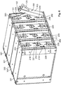
- Figure 6 finally shows an example in which the rack 300 is a multiple rack able to accommodate a plurality of electronic boards 200.
- the locking tool 100 according to the present invention can therefore be used in advantageous manner for locking or unlocking of each electronic board 200 of the multiple rack 300.
- a single tool 100 can be used for all the locking or unlocking operations of all the boards 200 of the multiple rack 300.
- the tool 100 can be left, as required, mounted at the back of one of the boards 200 in its locked state, as in figures 4 and 5 , or it can be detached to make the assembly more compact and lighter.
- the multiple rack 300 filled with electronic boards 200 compatible with the locking tool 100 will be more compact and lighter than if it were equipped with known electronic boards of the state of the art with an integrated lever connection system, which can present a considerable advantage in the case in which the multiple rack 300 would be used for the aeronautic industry or any application having limitations to the onboard load.
- Each rackable electronic board 200 will not only be lighter, but also cheaper than a known rackable electronic board of the state of the art integrating the whole connection system, while retaining all the advantages of reliability and locking.
- the present invention is not limited to the locking of rackable electronic boards in the aviation field, but can be adapted to any type of rackable pieces of electronic equipment used in other fields.
- the invention presents a considerable advantage relative to the known state of the art, given that a single tool is necessary to lock a set of electronic boards to a rack system, which allows reduction of the weight of each board, and therefore of the whole of the rack and of the onboard electronics, relative to known systems of the state of the art in which the board comprises an integrated locking lever.
- the invention presents an advantage relative to the known systems of the state of the art, in particular when the connection and disconnection forces become too great for manual locking mechanisms of inserter type, or for a saving of time relative to a coupling screw system.
Landscapes
- Engineering & Computer Science (AREA)
- Microelectronics & Electronic Packaging (AREA)
- Mounting Of Printed Circuit Boards And The Like (AREA)
Description
- The present invention relates to a locking and unlocking device for a rackable piece of electronic equipment such as a rackable electronic board.
- Pieces of equipment and in particular removable electronic boards able to be connected to a rack backplane connector are known in the state of the art. In the aviation field, given the strong vibrations experienced by the onboard electronic apparatus, in systems for locking rackable electronic boards, it is known to provide locking of the board to a rack backplane by a central screw system with prevention of unlocking by vibration. Such a system proves effective for the maintenance of locking but is expensive and slow to operate. Another integrated locking system is also known, with inserters, but proves limited in locking and unlocking power when the number of contacts to be connected becomes large.
- Moreover, equipment manufacturers, and particularly aircraft manufacturers, are constantly looking for savings in terms of costs, mass, reliability, assembly time on mounting and maintenance time of the different pieces of equipment. However, given that the electronic racks integrate more and more boards including in their turn an increasing number of contacts to be connected, the insertion and extraction forces of the boards are becoming larger and larger. Increasingly powerful and strong locking systems are therefore necessary, like the integrated connection system known from patent
EP 2 257 145 B1 , which discloses a hinged lever integrated at the back of a rackable electronic board and cooperating with locking strips of the board which allow hooking onto the backplane of the rack and, under the action of the lever, traction of the board so as to cause it to advance in the rack and to lock the assembly. However, such locking systems, although increasingly powerful and strong, are also increasingly heavy and costly. - An aim of the present invention is therefore to provide a solution to the above-mentioned problems and therefore to provide a quick, light and more economical connection system than the known systems, while providing at least as effective locking as the known systems.
- The aim is attained by a locking device for a rackable piece of electronic equipment, the device comprising a first mounting element and a second mounting element essentially forming a hinged lever able to cooperate with at least one locking organ of a rackable piece of electronic equipment so as to lock said rackable piece of electronic equipment with a rack backplane. According to the present invention, the locking device is removable and the locking device further comprises a spring arranged in a first longitudinal direction and a first end of which is linked to the first mounting element and a second end of which is linked to a hinged end movable in translation of the second mounting element.
- Thus, instead of an integrated locking system which increases the weight and the cost of the rackable pieces of electronic equipment, the present invention provides a removable tool able to be reused for locking or unlocking in succession a plurality of rackable electronic equipment to a rack backplane. The device according to the invention can advantageously be left mounted on the back of a rackable piece of electronic equipment once this has been locked to a rack, or detached in order to be reused to lock or unlock other rackable pieces of electronic equipment. A same device according to the invention can therefore advantageously be used for the locking or unlocking of a plurality of rackable pieces of electronic equipment.
- A locking and unlocking tool according to the invention thus has an advantage of cost and mass in particular for rack systems accommodating a plurality of rackable pieces of electronic equipment. Indeed, the known rack systems of the state of the art must make compatible the additional weight of each integrated locking system in each of the rackable pieces of electronic equipment locked in the rack, as well as their respective cost. Thus, by means of the present invention, the more rackable pieces of electronic equipment accommodated in the rack, the greater is the saving in weight and apparatus cost relative to the known integrated systems of the state of the art. This therefore presents a considerable advantage for equipment manufacturers and in particular for aircraft manufacturers.
- Moreover, the use of a removable tool permits manual connection or disconnection of rackable electronic boards equipped with several tens of contacts with reasonable force relative to the known systems, in particular those using inserters. Thus, in an embodiment of the present invention, the locking device can be used to lock at least one rackable electronic board in a rack backplane. In this case, after insertion of the board into the slideway of the rack, the locking device according to the present invention is mounted on the back of the board, and then actuated to provide, in cooperation with at least one locking organ of the board, locking of the board in the rack backplane. As required, the device according to the invention can then be left in place on the back of the board, or unmounted to lock or unlock other boards.
- Preferably, the first mounting element can extend in a first longitudinal direction and comprise a first end comprising at least one, in particular two, mounting members able to
cooperate with a respective locking organ of a rackable piece of electronic equipment. In an advantageous embodiment, the first end can thus be terminated by a first mounting member, in particular U-shaped. The device can then be mounted on the back of a rackable piece of electronic equipment so as to cooperate with a peg or a spindle of the rackable piece of electronic equipment, in particular of a movable locking organ of the rackable piece of electronic equipment, and thus form a locking lever. Moreover, in a preferred modified embodiment, the first mounting element can comprise in addition, in the direction of its first end, a second mounting member projecting essentially perpendicularly to the first longitudinal direction, and forming in particular a hook extending in the direction of said first end. Thus the device can be mounted so as to form a locking lever bearing on more than one, for example two points, for example two pegs or spindles, of the rackable piece of electronic equipment, one of which can be movable and the other fixed. - Preferably, the second mounting element can be an element permitting transmission of movement, extending in a second longitudinal direction, and a first end of which is hinged relative to the first mounting element. Thus, in an embodiment of the present invention, the second mounting element can be a rod or a similar piece hinged about a spindle passing through the first mounting element.
- Moreover, the hinged end of the second mounting element can advantageously in addition be movable in translation in the first longitudinal direction, in particular by sliding along a groove formed in the first mounting element. Thus, it is possible to provide transmission of the lever movement of the locking device so as to cause the other end of the second mounting element to cooperate with other locking organs of the rackable piece of electronic equipment.
- In an advantageous embodiment, a rod cooperating with a spring also linked to the first mounting element can therefore provide sensorial locking by return of the locking tool if the locking is not effective.
- Advantageously, the second mounting element can comprise a second end comprising at least one, in particular two, mounting member(s) able to cooperate with a respective locking organ of a rackable piece of electronic equipment. Thus in similar manner to the first mounting element, the second mounting element can also cooperate with at least one peg or spindle mounted at the back of the rackable piece of electronic equipment, in particular of one or more movable locking organs of the equipment. In a preferred embodiment, the second mounting element can therefore also comprise in addition, in the direction of the second end, a second mounting member projecting in essentially perpendicular manner to the second longitudinal direction, and forming in particular a hook extending in the direction of said second end. It is therefore possible to advantageously cause the locking device to cooperate with a plurality of fixed or movable locking organs, so as to cause a rackable piece of electronic equipment to advance in a rack and to lock it with the rack backplane.
- In an advantageous modification, the second mounting element can comprise in addition, in the direction of the second end, a locking member retracting into the second mounting element, and forming in particular a hook moving away from the second end. It is therefore possible to cause the locking member to cooperate with a fixed peg or spindle in the device in order to maintain the locking.
- Preferably, the locking device can comprise in addition a handle of longitudinal shape in which said first and second mounting elements are partially arranged. The device can therefore have a housing or a case in which the mounting elements are arranged and can therefore form a removable handle for rackable electronic equipment.
- In this case, the first mounting element can preferably be arranged in the handle in the first longitudinal direction and fixed relative to this, in particular so that the first mounting member of the first mounting element is projecting relative to the handle, in particular relative to an end of the handle, in the first longitudinal direction. In a preferred embodiment, the locking and unlocking tool can therefore form a removable handle, in which are mounted, on the one hand, the first mounting element in fixed manner, and on the other, the second mounting element in pivoting and/or sliding manner.
- Advantageously, the handle can comprise in addition at least one visual indicator of a state of locking and/or unlocking. Thus, the device according to the invention can also provide secure locking monitored by a visual indicator. According to preferred embodiments of this modification, a visual indicator can be for example a text or a coloured strip indicating the locking state.
- Preferably, the handle can comprise in addition a movable locking finger, in particular in translation, able to displace, in particular release, the second mounting element, in particular so as to facilitate unmounting of the locking device from a rackable piece of electronic equipment. Thus, depending on the position of the locking finger, it is possible to provide the maintenance or the unhooking of the locking device from a rackable piece of electronic equipment. According to the embodiment, the device according to the invention can therefore form a handle removable by actuation of a locking finger.
- In this case, it can be advantageous for the displacement to be performed by means of a spring cooperating with the locking finger. According to preferred modifications, the spring can be the same spring as that which can be used to return the second mounting element. In other modifications, it can also be a second spring which can also be arranged in the first longitudinal direction and cooperate on the one hand with the locking finger, and on the other with the second mounting element so as to push this back from a locked position towards an unlocked position permitting unmounting of the locking device from a rackable piece of electronic equipment.
- Moreover, said at least one visual indicator can then be visible depending on a position of the locking finger. Thus, it is possible to combine the position of the locking finger with the visual indication of the locking state.
- Finally, the aim is also attained by an assembly comprising at least one rackable electronic board equipped with a locking device according to the present invention and its modifications. According to the embodiments, the aim is also attained by an assembly of a plurality of rackable electronic boards inserted in a rack, in a locked state or otherwise, in which at least one of the rackable electronic boards is equipped with a locking device according to the present invention.
- Thus, a single locking device, otherwise called a single removable tool, advantageously permits locking and unlocking of all the rackable pieces of electronic equipment of a same rack, or more generally all the pieces of electronic equipment of a same type of rack. Consequently, in the case of multiple racks, the invention is the more advantageous as it permits the use of only a single tool for assembly of all the rackable pieces of electronic equipment of the different levels of a multiple rack. The mechanism for connection of the rackable electronic boards can therefore be simplified relative to the known boards of the state of the art integrating a locking system. The rackable electronic boards being able to be mounted by means of the locking device according to the invention can therefore allow the saving of weight, of cost, and increased simplicity relative to the rackable electronic boards known in the state of the art. In other words, the invention also allows lesser wear of the locking system and therefore increased reliability relative to the known systems. Moreover, in case of a problem with the locking, the invention allows changing of only the tool instead of having to change a whole electronic board, which would be the case for the known boards of the state of the art which integrate the locking system in non-removable manner.
- The present invention will be explained in more detail in the following description of advantageous embodiments based on the following accompanying figures, in which:
-
figure 1 is a perspective view of an example of the locking device according to an embodiment of the present invention; -
figure 2 is a perspective view of a locking step of a rackable piece of electronic equipment inserted in a rack, and of the locking device offigure 1 ; -
figure 3 is a perspective view of another locking step of the rackable piece of electronic equipment offigure 2 , showing the mounting of the locking device offigure 1 ; -
figure 4 is a detail of another locking step of the rackable piece of electronic equipment offigures 2 and3 , and of the locking device offigure 1 , showing a locked state; -
figure 5 is a view illustrating a locked state, but in a broader perspective than the detail offigure 4 ; and -
figure 6 is a perspective view showing the use of the locking device offigure 1 to lock one or more rackable pieces of electronic equipment in a multiple rack. -
Figure 1 is a perspective view of alocking tool 100 showing an example of an embodiment of a locking device according to the invention. According to the invention, thetool 100 is a removable tool allowing the locking and unlocking of a rackable piece of electronic equipment to a rack backplane. Contrarily to the locking systems integrated in the rackable electronic boards of the state of the art, thetool 100 is removable and can therefore be used for locking and unlocking of a plurality of rackable pieces of electronic equipment, which therefore allows saving of size and weight relative to integrated systems, but also in terms of production cost of the electronic boards given that these are simplified. - As shown in
figure 1 , alocking tool 100 according to the present invention therefore comprises a first mountingelement 101 and asecond mounting element 102, which is hinged relative to thefirst element 101, in particular in pivoting manner. Thus, thetool 100 essentially forms a hinged lever when it is mounted on the back of a rackable electronic board, as in the embodiment shown in the followingfigures 2 to 6 . - According to preferred and advantageous modifications of the invention,
figure 1 shows that thetool 100 can comprise anelongate handle part 103 which can be a housing comprising agroove 104 in which can be accommodated, and preferably fixed, the first mountingelement 101. Thehandle 103 can therefore comprises at least one transversal spindle providing the fixing of the first mountingelement 101. In the embodiment shown infigure 1 , thehandle 103 thus comprises at least twospindles element 101 in transversal manner. - Moreover, the two mounting
elements element 101 and thehandle 103 then extending in the same direction, which therefore defines a first relative longitudinal direction of thetool 100. The direction in which the second mountingelement 102 extends can then define a second relative longitudinal direction of thetool 100, forming a variable angle with the first longitudinal direction, depending on the relative position of the two mountingelements -
Figure 1 also shows that, according to preferred modified embodiments, thesecond element 102 can be a strip of rod type of which oneend 131 is passed through by aspindle 107, also passing through the first mountingelement 101, thus forming the hinge, in other words the pivot, between the two mountingelements strip 102, or rather theend 131, can be movable in translation relative to the first mountingelement 101, in particular by sliding in agroove 108 formed in the longitudinal direction of the first mountingelement 101. Similarly, thespindle 107 can pass through thegroove 108 from one side to the other and slide in thelateral grooves element 101, so that theend 131 can slide alonggrooves - According to another preferred modified embodiment,
figure 1 shows that in addition to pivoting relative to the first mountingelement 101, on the translation movement in thegroove 108, the second mountingelement 102 can also be returned by aspring 111, one end of which can be fixed to a peg orspindle 112 of thefirst element 101 and of thehandle 103 and the other end can be fixed to the projecting part of thespindle 107 relative to thegroove 109. -
Figure 1 also shows that, according to other advantageous modified embodiments, anend 113 of the first mountingelement 101 can be terminated by aU-shaped member 114. As also shown infigure 1 , themember 114 can be projecting in the first longitudinal direction as an extension of anend 116 of thehandle 103, in other words as an extension of theelement 101 in its longitudinal direction. Theelement 101 can also comprise, in the direction of theend 113, another mountingmember 115, this time projecting in essentially perpendicular manner to the first longitudinal direction, and forming a hook extending in the direction of theend 113. - In similar manner, the
free end 117 of the second mountingelement 102 can be extended in the second longitudinal direction by a mountingmember 118, which can also be U-shaped, and a second mountingmember 119 can be made in similar manner to themember 115 of thefirst element 101, i.e. in a hook projecting in perpendicular manner to thestrip 102 and extending in the direction of theend 117. - As shown below by the detailed examples with reference to
figures 2 and3 , the mountingmembers elements members hooks - According to another still advantageous modified embodiment,
figure 1 shows in addition that opposite to the projecting mountingmember 119 can be situated a lockingmember 120 retracting into thestrip 102 or forming a cavity in thestrip 102 giving the member 120 a hook shape extending in an opposite direction to that of thehook 119. As shown more closely infigure 4 , thehook 120 can catch onto aspindle 123 inside thetool 100 so as to maintain the locking. -
Figure 1 also shows that the second then 122 thehandle 103, as well as thesecond end 124 of thefirst element 101, can be open so as to allow retraction of thesecond element 102 when this pivots towards the locked position, as infigure 4 . In this case, just above thehook 120, in the direction of theend 117 of the mountingelement 102, can be situated anotch 121 allowing the mountingelement 102 to be received in thegroove 108, in the locked position of the system, without being hampered by thespindle 106. - According to yet another modified embodiment, the
tool 100 can also comprise a lockingfinger 125, visible infigure 1 , mounted in movable manner on thehandle 103, in particular in sliding manner, and the action of which will be better understood by means offigure 4 . -
Figure 2 is a partial perspective view of a rackableelectronic board 200 inserted in arack 300, also showing thelocking tool 100 of the embodiment shown infigure 1 before mounting on the back of theboard 200. In this step, theelectronic board 200 is inserted in thecase 301 of therack 300 but is not yet locked with the rack backplane 302 (not shown infigure 2 , but visible infigure 5 ). The insertion can be effected manually by causing theboard 200 to slide in a slideway (not shown) of therack 300. The part not shown of theboard 200, or "front" part of theboard 200, can include a plurality of electrical contacts intended to be plugged into thebackplane 302 of therack 300, which can therefore include counterpart electrical contacts. The part of theelectronic board 200 visible infigure 2 can therefore also be called the "back" part of theboard 200. - Like certain known electronic boards of the state of the art, the
board 200 of the embodiment shown infigure 2 and in the following figures, comprises integrated locking organs permitting locking to the backplane of therack 300. However, contrarily to the known integrated locking systems of the state of the art, theelectronic board 200 of the embodiment shown infigure 2 does not include an integrated locking lever, locking being performed by mounting and actuation of theremovable locking tool 100 of the embodiment shown infigure 1 , which, once theboard 200 is locked in therack 300, can be unmounted from the back of theboard 200 and reused to lock or unlock other boards. Consequently, theelectronic board 200 is lighter and less costly to manufacture than the known electronic boards of the state of the art with an integrated locking system. -
Figure 2 shows in addition that theelectronic board 200 can include at least one movable locking organ and a least one corresponding fixed locking organ, permitting locking of it to the backplane of therack 300 by lever effect of thetool 100. Advantageously, in the embodiment shown infigure 2 and in the following figures, theelectronic board 200 thus includes pairs of locking organs, one mobile and the other fixed relative to thecase 201 of theboard 200, able to cooperate with the pairs of mountingorgans locking tool 100. Thus, theboard 200 includes the first movable 202 and fixed 204 locking organs, on the one hand, and the second movable 203 and fixed 205 locking organs, on the other. As shown infigures 2 et seq., themovable locking organs organs elements tool 100. Similarly, the fixed lockingorgans hooks locking tool 100, thus creating the desired lever effect. -
Figure 2 shows a possible strategy for mounting thetool 100 at the back of theelectronic board 200. In this embodiment, the arrangement of the pairs of lockingorgans tool 100 can be performed either according to the example shown, or in symmetrical manner. In other words, the pair of mountingorgans organs organs organs figures 2 et seq. However, in other embodiments, if the pair of mountingorgans organs organs organs 202, 204 (reversed position not illustrated of the tool 100). -
Figure 3 shows thelocking tool 100 in position on the back of theboard 200, thecase 201 of which has been made transparent in order to show the locking organs of theboard 200. The U-shaped mountingorgan 114 is positioned on aspindle 206 of themovable locking organ 202, the latter comprising in addition alocking strip 210 one end of which can be wound round thespindle 206, the other part (not shown) being used for locking on the backplane of therack 300. Aspindle 208 of the fixed lockingorgan 204 can then be hooked by the associatedhook 115 of the first mountingelement 101. Similarly, thepivoting mounting element 102 can form an angle with the fixed mountingelement 101 of thetool 100, which permits, also under the action of thespring 111, positioning of the other U-shaped mountingorgan 118 against aspindle 208 of the other movable lockingorgan 203, and also hooking of aspindle 209 of the other fixed lockingorgan 205 by means of thehook 119. Like the other movable lockingorgan 202, the lockingorgan 203 can also include alocking strip 211 an end of which can be wound around thespindle 207 and the other part of which is also used for locking on the backplane of therack 300. - A lever movement folding the
tool 100 in the direction of theboard 200 can then allow traction of theboard 200 and locking of it to the backplane of therack 300 by means of the locking strips 210, 211. By lever effect of thehooks spindles organs organs movable locking organs board 200 advance to its locking position in the backplane of therack 300, as shown in particular infigures 4 to 6 . Thus, when thelocking tool 100 is actuated and mounted in its locking position, the second mountingelement 102 is pivoted flat in thegroove 108, as shown in the sectional view offigure 4 , so that thehook 120 hooks thespindle 123, thenotch 121 surrounds thespindle 106, and thefree end 117 of the second mountingelement 102 is projecting from theend 122 of thehandle 103 in similar manner to theend 113 of the first mountingelement 101 relative to theother end 116 of thehandle 103. Thespring 111 can be stretched and cause the mountingmembers spindles - With reference in particular to
figure 3 , theelectronic board 200 can also comprise a self-locking or secondary locking system ensuring the maintenance of the locking of theboard 200 in therack 300 in order to unmount thetool 100 for reuse with other rackable pieces of electronic equipment. Theboard 200 can therefore comprise alocking button 214 cooperating with two secondary locking strips 215, 216 which, as soon as themovable locking organs tool 100, can be stopped in respective secondary locking stops 212, 213 of theorgans stops figure 3 , thestop 212 being shown moreover in more detail infigure 4 . In this manner, once thestrips organs rack 300, the secondary locking strips 215, 216 ensure the maintenance of the locked position of the main locking strips 210, 211 in the backplane of therack 302 and then allow thetool 100 to be unmounted without risk of disconnection. - The unmounting of the
tool 100 can then be performed by actuation of theend 126 of the lockingfinger 125, thus causing the descent of the lockingfinger 125, which can finally release thespindle 123 from thehook 120, and thus cause the second mountingelement 102 to slide or pivot in thegroove 108 and about thespindle 107 so as to disengage the mountingmembers spindles finger 125 can comprise in addition alug 127 which, on the actuation of thefinger 125, can compress aspring 128, visible infigure 4 , able to be linked to the second mountingelement 102 of thetool 100. Once themembers tool 100 can be simply unmounted from theboard 200 and reused to lock or unlock other rackable pieces of electronic equipment, while leaving theboard 200 locked in therack 300 by means of the secondary locking strips 215, 216, which are visible infigure 3 but have been concealed infigure 4 to show the detail of thestop 212 of themovable locking organ 203. -
Figure 5 shows theelectronic board 200 locked to therack backplane 302, with thecase 301 of therack 300 concealed, and with thelocking tool 100 mounted in the locked position. The locking position or state can be indicated in a plurality of manners, in particular by means of visual indicators such as texts, coloured strips, combinations of these or other similar means. - For example
figures 2 to 5 showvisual indicators handle 103 of thelocking tool 100. In particular, theseindicators handle 103, at the ends of the lockingfinger 125, so that in the locked state, when the lockingfinger 125 is in its upper position as shown, anindicator 129 corresponding to the locked state can be visible below the lockingfinger 125. Conversely, if the lockingfinger 125 is actuated,figure 4 allows anotherindicator 130 to be seen, which will be visible in the lower position of thefinger 125, therefore corresponding to an unlocked state allowing thetool 100 to be unmounted from the back of a rackable piece of electronic equipment. - Similarly, a rackable piece of electronic equipment compatible with the
locking tool 100 can itself also comprise an indicator of a locking state. Thus, as shown infigures 2 ,3 ,5 and6 , thecase 201 of theelectronic board 200 can comprisevisual indicators visual indicator 221 of thelocking button 214 in a locked or unlocked state of theboard 200. For example, in the example embodiments shown infigures 2 to 6 ,figures 2 and3 show an unlocked state of theboard 200, in which theindicator 221 of thebutton 214 is turned towards theunlocked state indicator 219 of thecase 201, whilefigure 6 shows a locked state of eachboard 200 in themultiple rack 300, with theindicator 221 of thebutton 214 turned towards the lockedstate indicators case 201. - In the embodiments shown, each of the U-shaped mounting
members elements locking button 214, for example in a direction which can be indicated by avisual indicator 220 on thecase 201 of theelectronic board 200, so as to disengage the secondary locking strips 215, 216 from thestops board 200 can then be unlocked from therack 300 by mounting thetool 100 at the back of this board, as infigure 3 , and by pulling on thetool 100 instead of levering towards theboard 200. -
Figure 6 finally shows an example in which therack 300 is a multiple rack able to accommodate a plurality ofelectronic boards 200. Thelocking tool 100 according to the present invention can therefore be used in advantageous manner for locking or unlocking of eachelectronic board 200 of themultiple rack 300. In particular, asingle tool 100 can be used for all the locking or unlocking operations of all theboards 200 of themultiple rack 300. Thetool 100 can be left, as required, mounted at the back of one of theboards 200 in its locked state, as infigures 4 and5 , or it can be detached to make the assembly more compact and lighter. Whichever the case, themultiple rack 300 filled withelectronic boards 200 compatible with thelocking tool 100 will be more compact and lighter than if it were equipped with known electronic boards of the state of the art with an integrated lever connection system, which can present a considerable advantage in the case in which themultiple rack 300 would be used for the aeronautic industry or any application having limitations to the onboard load. Each rackableelectronic board 200 will not only be lighter, but also cheaper than a known rackable electronic board of the state of the art integrating the whole connection system, while retaining all the advantages of reliability and locking. Moreover, in the case of problems with thelocking tool 100, this alone will have to be replaced to continue the operations on a whole set ofelectronic boards 200, which presents another advantage relative to the replacement of a whole electronic board with an integrated connection system such as those known of the state of the art. - As is apparent from the preceding description, the present invention is not limited to the locking of rackable electronic boards in the aviation field, but can be adapted to any type of rackable pieces of electronic equipment used in other fields. However, in the particular field of Aeronautics, in which the weight of the onboard systems plays a leading role, and in associated fields, the invention presents a considerable advantage relative to the known state of the art, given that a single tool is necessary to lock a set of electronic boards to a rack system, which allows reduction of the weight of each board, and therefore of the whole of the rack and of the onboard electronics, relative to known systems of the state of the art in which the board comprises an integrated locking lever. Moreover, the invention presents an advantage relative to the known systems of the state of the art, in particular when the connection and disconnection forces become too great for manual locking mechanisms of inserter type, or for a saving of time relative to a coupling screw system.
-
- 100
- locking tool
- 101
- first mounting element
- 102
- second mounting element, rod
- 103
- handle
- 104
- groove
- 105
- spindle
- 106
- spindle
- 107
- spindle
- 108
- groove
- 109
- lateral groove
- 110
- lateral groove
- 111
- spring
- 112
- spindle
- 113
- end of the first mounting element
- 114
- mounting member
- 115
- mounting member, hook
- 116
- end of the handle
- 117
- free end of the second mounting element
- 118
- mounting member
- 119
- mounting member, hook
- 120
- locking member, hook
- 121
- notch
- 122
- end of the handle
- 123
- spindle
- 124
- end of the first mounting element
- 125
- locking finger
- 126
- end of the locking finger
- 127
- lug
- 128
- spring
- 129
- marking of the locked state
- 130
- marking of the unlocked state
- 131
- end of the second mounting element
- 200
- rackable electronic board
- 201
- electronic board case
- 202
- movable locking organ
- 203
- movable locking organ
- 204
- fixed locking organ
- 205
- fixed locking organ
- 206
- spindle
- 207
- spindle
- 208
- spindle
- 209
- spindle
- 210
- locking strip
- 211
- locking strip
- 212
- secondary locking stop
- 213
- secondary locking stop
- 214
- locking button
- 215
- secondary locking strip
- 216
- secondary locking strip
- 217
- locked state indicator
- 218
- locked state indicator
- 219
- unlocked state indicator
- 220
- unlocking direction
- 221
- locked state indicator
- 300
- rack
- 301
- rack case
- 302
- back plane of rack
Claims (12)
- Locking device (100) of a rackable piece of electronic equipment, the device comprising:a first mounting element (101) and a second mounting element (102) essentially forming a hinged lever able to cooperate with at least one locking organ of a rackable piece of electronic equipment so as to lock said rackable piece of electronic equipment with a rack backplane,characterised in thatthe locking device (100) is removable and in that the locking device further comprises a spring (111) arranged in a first longitudinal direction and a first end of which is linked to the first mounting element (101) and a second end of which is linked to a hinged end movable in translation (131) of the second mounting element (102).
- Locking device (100) according to claim 1, in which the first mounting element (101) extends in a first longitudinal direction and comprises a first end (113) comprising at least one, preferably two, mounting member(s) (114, 115) able to cooperate with a respective locking organ of a rackable piece of electronic equipment.
- Locking device (100) according to any one of the preceding claims, in which the second mounting element (102) extends in a second longitudinal direction and comprises a first end (131) hinged relative to the first mounting element (101).
- Locking device (100) according to claim 3, in which the hinged end (131) of the second mounting element (102) is in addition movable in translation along the first longitudinal direction, in particular by sliding along at least one groove (108) formed in the first mounting element (101).
- Locking device (100) according to claim 3 or 4, in which the second mounting element (102) comprises a second end (117) comprising at least one, preferably two, mounting member(s) (118, 119) able to cooperate with a respective locking organ of a rackable piece of electronic equipment.
- Locking device (100) according to claim 5, in which the second mounting element (102) comprises in addition, in the direction of its second end (117), a locking member (120) retracting into the second mounting element (102), and forming in particular a hook departing from said second end (117).
- Locking device (100) according to any one of the preceding claims, comprising in addition a handle (103) of longitudinal form in which are partially arranged said first and second mounting elements (101, 102).
- Locking device (100) according to claim 7, in which the first mounting element (101) is arranged in the handle (103) in a first longitudinal direction and is fixed relative to this, in particular, in combination with claim 2, so that said at least one mounting member (114, 115) of the first mounting element (101) is projecting relative to the handle (103), in particular relative to an end (116) of the handle (103).
- Locking device (100) according to any one of claims 7 or 8, in which the handle (103) comprises in addition a visual indicator (129, 130) of a locking and/or unlocking state.
- Locking device (100) according to any one of claims 7 to 9, in which the handle (103) comprises in addition a locking finger (125) movable, in particular in translation, able to displace, in particular release, the second mounting element (102), in particular so as to facilitate the unmounting of the locking device (100) from a rackable piece of electronic equipment (200).
- Locking device (100) according to claim 10 in combination with claim 9, in which said at least one visual indicator (129, 130) is visible depending on a position of the locking finger (125).
- Assembly including at least one rackable electronic board (200) equipped with a locking device (100) according to one of the preceding claims.
Applications Claiming Priority (2)
| Application Number | Priority Date | Filing Date | Title |
|---|---|---|---|
| FR1457414A FR3024634B1 (en) | 2014-07-31 | 2014-07-31 | LOCKING DEVICE FOR RACKABLE ELECTRONIC EQUIPMENT |
| PCT/EP2015/067563 WO2016016392A1 (en) | 2014-07-31 | 2015-07-30 | Locking device for rackable electronic equipment |
Publications (2)
| Publication Number | Publication Date |
|---|---|
| EP3175686A1 EP3175686A1 (en) | 2017-06-07 |
| EP3175686B1 true EP3175686B1 (en) | 2019-02-20 |
Family
ID=51688290
Family Applications (1)
| Application Number | Title | Priority Date | Filing Date |
|---|---|---|---|
| EP15753621.0A Active EP3175686B1 (en) | 2014-07-31 | 2015-07-30 | Locking device for rackable electronic equipment |
Country Status (5)
| Country | Link |
|---|---|
| US (1) | US10462922B2 (en) |
| EP (1) | EP3175686B1 (en) |
| CN (1) | CN106576435B (en) |
| FR (1) | FR3024634B1 (en) |
| WO (1) | WO2016016392A1 (en) |
Families Citing this family (11)
| Publication number | Priority date | Publication date | Assignee | Title |
|---|---|---|---|---|
| US11039546B2 (en) | 2015-12-25 | 2021-06-15 | Ting-Jui Wang | Pull-out aiding device and chassis-wall module with pull-out aiding function |
| TWM522487U (en) * | 2015-12-25 | 2016-05-21 | 伍鐌科技股份有限公司 | Pull-up device and machine board module with pull-up function |
| CN205959139U (en) * | 2016-07-22 | 2017-02-15 | 中兴通讯股份有限公司 | Module auto -lock, integrative constructional device of interlocking |
| CN109958696B (en) * | 2017-12-22 | 2021-08-17 | 王鼎瑞 | Quick release rod body |
| US11489274B2 (en) * | 2017-12-22 | 2022-11-01 | Ting-Jui Wang | Quick release connecting device |
| TWI695123B (en) * | 2017-12-29 | 2020-06-01 | 伍鐌科技股份有限公司 | Fastening structure |
| TWI816117B (en) * | 2021-05-08 | 2023-09-21 | 新加坡商鴻運科股份有限公司 | Function module lock device and function module |
| US11617279B2 (en) | 2021-08-20 | 2023-03-28 | Raytheon Company | Brake for an electronic component |
| WO2023049756A1 (en) | 2021-09-21 | 2023-03-30 | Sharfi Benjamin K | Rugged utility ultra slim self-locking ejector device |
| TWI824922B (en) * | 2023-01-13 | 2023-12-01 | 和碩聯合科技股份有限公司 | Server apparatus |
| FR3166511A1 (en) * | 2024-09-18 | 2026-03-20 | Safran Electronics & Defense | System for inserting, extracting and locking a computer in a rack, in particular an aircraft avionics bay, comprising at least one lever. |
Family Cites Families (15)
| Publication number | Priority date | Publication date | Assignee | Title |
|---|---|---|---|---|
| US5268821A (en) * | 1991-03-06 | 1993-12-07 | Tandem Computers Incorporated | Shared pc board ejector/injector tool |
| DE19801719C2 (en) * | 1998-01-19 | 2001-11-22 | Loh Kg Rittal Werk | Control cabinet lock |
| FR2779901B1 (en) * | 1998-06-12 | 2000-09-01 | Sextant Avionique | DEVICE FOR INSERTING, EXTRACTING AND LOCKING A MODULE IN A BAY |
| US6816383B2 (en) * | 2002-07-12 | 2004-11-09 | International Business Machines Corporation | Cassette housing for printed circuit cards |
| US6754074B2 (en) * | 2002-09-09 | 2004-06-22 | Hewlett-Packard Development Company, L.P. | Multipurpose server handle |
| JP2004343061A (en) * | 2003-03-24 | 2004-12-02 | Schroff Gmbh | Plug-in module for insertion and extraction from module frame |
| JP4603459B2 (en) | 2005-10-14 | 2010-12-22 | 富士通株式会社 | Card unit |
| US8203851B2 (en) * | 2009-02-09 | 2012-06-19 | Juniper Networks, Inc. | Retention-extraction device for removable cards in a chassis |
| FR2946188B1 (en) * | 2009-05-28 | 2011-08-26 | Connecteurs Electr Deutsch | CONNECTING DEVICE |
| US8749966B1 (en) * | 2009-12-22 | 2014-06-10 | Emc Corporation | Data storage drive carrier |
| TWI459383B (en) * | 2010-10-29 | 2014-11-01 | Ibm | Carrier, host, and method of assembling the host |
| US8369080B2 (en) * | 2011-02-25 | 2013-02-05 | Jui-Shu Huang | Removable hard disk drive bay |
| CN102361207A (en) * | 2011-10-10 | 2012-02-22 | 福建敏讯信息技术有限公司 | Universal puller for PCB (Printed Circuit Board) of communication chassis |
| FR3002409B1 (en) * | 2013-02-20 | 2016-06-03 | Bull Sas | CALCULATION BLADE FOR MOUNTABLE SERVER ON BATI |
| TWI550194B (en) * | 2014-04-10 | 2016-09-21 | Wang Ding Rui | Fast split body |
-
2014
- 2014-07-31 FR FR1457414A patent/FR3024634B1/en active Active
-
2015
- 2015-07-30 CN CN201580041337.XA patent/CN106576435B/en active Active
- 2015-07-30 WO PCT/EP2015/067563 patent/WO2016016392A1/en not_active Ceased
- 2015-07-30 EP EP15753621.0A patent/EP3175686B1/en active Active
-
2017
- 2017-01-27 US US15/417,352 patent/US10462922B2/en active Active
Non-Patent Citations (1)
| Title |
|---|
| None * |
Also Published As
| Publication number | Publication date |
|---|---|
| CN106576435B (en) | 2019-11-26 |
| EP3175686A1 (en) | 2017-06-07 |
| WO2016016392A1 (en) | 2016-02-04 |
| FR3024634B1 (en) | 2016-08-12 |
| US10462922B2 (en) | 2019-10-29 |
| US20170135241A1 (en) | 2017-05-11 |
| CN106576435A (en) | 2017-04-19 |
| FR3024634A1 (en) | 2016-02-05 |
Similar Documents
| Publication | Publication Date | Title |
|---|---|---|
| EP3175686A1 (en) | Locking device for rackable electronic equipment | |
| EP2979326B1 (en) | Supporting frame construction for modular connectors | |
| US6695520B1 (en) | Device for inserting, extracting and locking a module in a bay | |
| DE102008034131B4 (en) | plug socket | |
| AU2015252083B2 (en) | Assembly For Connecting A Roof Rack To A Vehicle | |
| EP3578716B1 (en) | Remote control holder for a paver | |
| KR102091959B1 (en) | Small store suspension and release unit | |
| US9816301B2 (en) | Locking device with mechanical detection of closing and opening | |
| DE102010053746A1 (en) | System for securing a seat, in particular an aircraft seat, and seat with at least one such system | |
| EP2265492A1 (en) | Fastening system and method for fastening an element of airplane interior equipment | |
| WO2009030315A1 (en) | Locking mechanism for a housing to hold a plug-in module | |
| EP2214269B1 (en) | Interface device | |
| EP2861469B1 (en) | Wiper blade adapter system | |
| DE102020102749A1 (en) | Vibration-proof modular computer system | |
| US9150309B2 (en) | Fastening system for hanging mountable overhead containers | |
| US8550260B1 (en) | Aircraft control panel assembly | |
| GB2076946A (en) | Securing payloads to aircraft | |
| US9169019B2 (en) | Fastening system for suspended overhead storage bins | |
| EP2603067B1 (en) | Locking device | |
| AT506980B1 (en) | LUGGAGE STORAGE FOR A PASSENGER AIRPLANE | |
| DE102008058425B4 (en) | System for accommodating at least one item of luggage in a cabin of a vehicle | |
| US20180204690A1 (en) | Integration of electrical contacts in an electrical switching device | |
| DE102007030422B4 (en) | Holder for releasably securing a trim panel in an aircraft | |
| CN210819405U (en) | Assembled jump ring dismouting mechanism | |
| US2089649A (en) | Quick detachable clevis |
Legal Events
| Date | Code | Title | Description |
|---|---|---|---|
| STAA | Information on the status of an ep patent application or granted ep patent |
Free format text: STATUS: THE INTERNATIONAL PUBLICATION HAS BEEN MADE |
|
| 17P | Request for examination filed |
Effective date: 20170222 |
|
| AK | Designated contracting states |
Kind code of ref document: A1 Designated state(s): AL AT BE BG CH CY CZ DE DK EE ES FI FR GB GR HR HU IE IS IT LI LT LU LV MC MK MT NL NO PL PT RO RS SE SI SK SM TR |
|
| AX | Request for extension of the european patent |
Extension state: BA ME |
|
| PUAI | Public reference made under article 153(3) epc to a published international application that has entered the european phase |
Free format text: ORIGINAL CODE: 0009012 |
|
| STAA | Information on the status of an ep patent application or granted ep patent |
Free format text: STATUS: REQUEST FOR EXAMINATION WAS MADE |
|
| DAV | Request for validation of the european patent (deleted) | ||
| DAX | Request for extension of the european patent (deleted) | ||
| GRAP | Despatch of communication of intention to grant a patent |
Free format text: ORIGINAL CODE: EPIDOSNIGR1 |
|
| STAA | Information on the status of an ep patent application or granted ep patent |
Free format text: STATUS: GRANT OF PATENT IS INTENDED |
|
| INTG | Intention to grant announced |
Effective date: 20180831 |
|
| RIN1 | Information on inventor provided before grant (corrected) |
Inventor name: MOREAU, JEAN-LUC |
|
| GRAS | Grant fee paid |
Free format text: ORIGINAL CODE: EPIDOSNIGR3 |
|
| GRAA | (expected) grant |
Free format text: ORIGINAL CODE: 0009210 |
|
| STAA | Information on the status of an ep patent application or granted ep patent |
Free format text: STATUS: THE PATENT HAS BEEN GRANTED |
|
| AK | Designated contracting states |
Kind code of ref document: B1 Designated state(s): AL AT BE BG CH CY CZ DE DK EE ES FI FR GB GR HR HU IE IS IT LI LT LU LV MC MK MT NL NO PL PT RO RS SE SI SK SM TR |
|
| REG | Reference to a national code |
Ref country code: GB Ref legal event code: FG4D |
|
| REG | Reference to a national code |
Ref country code: CH Ref legal event code: EP |
|
| REG | Reference to a national code |
Ref country code: DE Ref legal event code: R096 Ref document number: 602015024906 Country of ref document: DE |
|
| REG | Reference to a national code |
Ref country code: AT Ref legal event code: REF Ref document number: 1099978 Country of ref document: AT Kind code of ref document: T Effective date: 20190315 |
|
| REG | Reference to a national code |
Ref country code: IE Ref legal event code: FG4D |
|
| REG | Reference to a national code |
Ref country code: LT Ref legal event code: MG4D |
|
| REG | Reference to a national code |
Ref country code: NL Ref legal event code: MP Effective date: 20190220 |
|
| PG25 | Lapsed in a contracting state [announced via postgrant information from national office to epo] |
Ref country code: FI Free format text: LAPSE BECAUSE OF FAILURE TO SUBMIT A TRANSLATION OF THE DESCRIPTION OR TO PAY THE FEE WITHIN THE PRESCRIBED TIME-LIMIT Effective date: 20190220 Ref country code: NO Free format text: LAPSE BECAUSE OF FAILURE TO SUBMIT A TRANSLATION OF THE DESCRIPTION OR TO PAY THE FEE WITHIN THE PRESCRIBED TIME-LIMIT Effective date: 20190520 Ref country code: LT Free format text: LAPSE BECAUSE OF FAILURE TO SUBMIT A TRANSLATION OF THE DESCRIPTION OR TO PAY THE FEE WITHIN THE PRESCRIBED TIME-LIMIT Effective date: 20190220 Ref country code: ES Free format text: LAPSE BECAUSE OF FAILURE TO SUBMIT A TRANSLATION OF THE DESCRIPTION OR TO PAY THE FEE WITHIN THE PRESCRIBED TIME-LIMIT Effective date: 20190220 Ref country code: SE Free format text: LAPSE BECAUSE OF FAILURE TO SUBMIT A TRANSLATION OF THE DESCRIPTION OR TO PAY THE FEE WITHIN THE PRESCRIBED TIME-LIMIT Effective date: 20190220 Ref country code: PT Free format text: LAPSE BECAUSE OF FAILURE TO SUBMIT A TRANSLATION OF THE DESCRIPTION OR TO PAY THE FEE WITHIN THE PRESCRIBED TIME-LIMIT Effective date: 20190620 |
|
| PG25 | Lapsed in a contracting state [announced via postgrant information from national office to epo] |
Ref country code: LV Free format text: LAPSE BECAUSE OF FAILURE TO SUBMIT A TRANSLATION OF THE DESCRIPTION OR TO PAY THE FEE WITHIN THE PRESCRIBED TIME-LIMIT Effective date: 20190220 Ref country code: RS Free format text: LAPSE BECAUSE OF FAILURE TO SUBMIT A TRANSLATION OF THE DESCRIPTION OR TO PAY THE FEE WITHIN THE PRESCRIBED TIME-LIMIT Effective date: 20190220 Ref country code: NL Free format text: LAPSE BECAUSE OF FAILURE TO SUBMIT A TRANSLATION OF THE DESCRIPTION OR TO PAY THE FEE WITHIN THE PRESCRIBED TIME-LIMIT Effective date: 20190220 Ref country code: IS Free format text: LAPSE BECAUSE OF FAILURE TO SUBMIT A TRANSLATION OF THE DESCRIPTION OR TO PAY THE FEE WITHIN THE PRESCRIBED TIME-LIMIT Effective date: 20190620 Ref country code: BG Free format text: LAPSE BECAUSE OF FAILURE TO SUBMIT A TRANSLATION OF THE DESCRIPTION OR TO PAY THE FEE WITHIN THE PRESCRIBED TIME-LIMIT Effective date: 20190520 Ref country code: HR Free format text: LAPSE BECAUSE OF FAILURE TO SUBMIT A TRANSLATION OF THE DESCRIPTION OR TO PAY THE FEE WITHIN THE PRESCRIBED TIME-LIMIT Effective date: 20190220 Ref country code: GR Free format text: LAPSE BECAUSE OF FAILURE TO SUBMIT A TRANSLATION OF THE DESCRIPTION OR TO PAY THE FEE WITHIN THE PRESCRIBED TIME-LIMIT Effective date: 20190521 |
|
| REG | Reference to a national code |
Ref country code: AT Ref legal event code: MK05 Ref document number: 1099978 Country of ref document: AT Kind code of ref document: T Effective date: 20190220 |
|
| PG25 | Lapsed in a contracting state [announced via postgrant information from national office to epo] |
Ref country code: DK Free format text: LAPSE BECAUSE OF FAILURE TO SUBMIT A TRANSLATION OF THE DESCRIPTION OR TO PAY THE FEE WITHIN THE PRESCRIBED TIME-LIMIT Effective date: 20190220 Ref country code: EE Free format text: LAPSE BECAUSE OF FAILURE TO SUBMIT A TRANSLATION OF THE DESCRIPTION OR TO PAY THE FEE WITHIN THE PRESCRIBED TIME-LIMIT Effective date: 20190220 Ref country code: SK Free format text: LAPSE BECAUSE OF FAILURE TO SUBMIT A TRANSLATION OF THE DESCRIPTION OR TO PAY THE FEE WITHIN THE PRESCRIBED TIME-LIMIT Effective date: 20190220 Ref country code: AL Free format text: LAPSE BECAUSE OF FAILURE TO SUBMIT A TRANSLATION OF THE DESCRIPTION OR TO PAY THE FEE WITHIN THE PRESCRIBED TIME-LIMIT Effective date: 20190220 Ref country code: CZ Free format text: LAPSE BECAUSE OF FAILURE TO SUBMIT A TRANSLATION OF THE DESCRIPTION OR TO PAY THE FEE WITHIN THE PRESCRIBED TIME-LIMIT Effective date: 20190220 Ref country code: IT Free format text: LAPSE BECAUSE OF FAILURE TO SUBMIT A TRANSLATION OF THE DESCRIPTION OR TO PAY THE FEE WITHIN THE PRESCRIBED TIME-LIMIT Effective date: 20190220 Ref country code: RO Free format text: LAPSE BECAUSE OF FAILURE TO SUBMIT A TRANSLATION OF THE DESCRIPTION OR TO PAY THE FEE WITHIN THE PRESCRIBED TIME-LIMIT Effective date: 20190220 |
|
| REG | Reference to a national code |
Ref country code: DE Ref legal event code: R097 Ref document number: 602015024906 Country of ref document: DE |
|
| PG25 | Lapsed in a contracting state [announced via postgrant information from national office to epo] |
Ref country code: SM Free format text: LAPSE BECAUSE OF FAILURE TO SUBMIT A TRANSLATION OF THE DESCRIPTION OR TO PAY THE FEE WITHIN THE PRESCRIBED TIME-LIMIT Effective date: 20190220 Ref country code: PL Free format text: LAPSE BECAUSE OF FAILURE TO SUBMIT A TRANSLATION OF THE DESCRIPTION OR TO PAY THE FEE WITHIN THE PRESCRIBED TIME-LIMIT Effective date: 20190220 |
|
| PLBE | No opposition filed within time limit |
Free format text: ORIGINAL CODE: 0009261 |
|
| STAA | Information on the status of an ep patent application or granted ep patent |
Free format text: STATUS: NO OPPOSITION FILED WITHIN TIME LIMIT |
|
| PG25 | Lapsed in a contracting state [announced via postgrant information from national office to epo] |
Ref country code: AT Free format text: LAPSE BECAUSE OF FAILURE TO SUBMIT A TRANSLATION OF THE DESCRIPTION OR TO PAY THE FEE WITHIN THE PRESCRIBED TIME-LIMIT Effective date: 20190220 |
|
| 26N | No opposition filed |
Effective date: 20191121 |
|
| PG25 | Lapsed in a contracting state [announced via postgrant information from national office to epo] |
Ref country code: MC Free format text: LAPSE BECAUSE OF FAILURE TO SUBMIT A TRANSLATION OF THE DESCRIPTION OR TO PAY THE FEE WITHIN THE PRESCRIBED TIME-LIMIT Effective date: 20190220 Ref country code: SI Free format text: LAPSE BECAUSE OF FAILURE TO SUBMIT A TRANSLATION OF THE DESCRIPTION OR TO PAY THE FEE WITHIN THE PRESCRIBED TIME-LIMIT Effective date: 20190220 |
|
| REG | Reference to a national code |
Ref country code: CH Ref legal event code: PL |
|
| PG25 | Lapsed in a contracting state [announced via postgrant information from national office to epo] |
Ref country code: TR Free format text: LAPSE BECAUSE OF FAILURE TO SUBMIT A TRANSLATION OF THE DESCRIPTION OR TO PAY THE FEE WITHIN THE PRESCRIBED TIME-LIMIT Effective date: 20190220 |
|
| REG | Reference to a national code |
Ref country code: BE Ref legal event code: MM Effective date: 20190731 |
|
| PG25 | Lapsed in a contracting state [announced via postgrant information from national office to epo] |
Ref country code: BE Free format text: LAPSE BECAUSE OF NON-PAYMENT OF DUE FEES Effective date: 20190731 Ref country code: LU Free format text: LAPSE BECAUSE OF NON-PAYMENT OF DUE FEES Effective date: 20190730 Ref country code: CH Free format text: LAPSE BECAUSE OF NON-PAYMENT OF DUE FEES Effective date: 20190731 Ref country code: LI Free format text: LAPSE BECAUSE OF NON-PAYMENT OF DUE FEES Effective date: 20190731 |
|
| PG25 | Lapsed in a contracting state [announced via postgrant information from national office to epo] |
Ref country code: IE Free format text: LAPSE BECAUSE OF NON-PAYMENT OF DUE FEES Effective date: 20190730 |
|
| PG25 | Lapsed in a contracting state [announced via postgrant information from national office to epo] |
Ref country code: CY Free format text: LAPSE BECAUSE OF FAILURE TO SUBMIT A TRANSLATION OF THE DESCRIPTION OR TO PAY THE FEE WITHIN THE PRESCRIBED TIME-LIMIT Effective date: 20190220 |
|
| PG25 | Lapsed in a contracting state [announced via postgrant information from national office to epo] |
Ref country code: HU Free format text: LAPSE BECAUSE OF FAILURE TO SUBMIT A TRANSLATION OF THE DESCRIPTION OR TO PAY THE FEE WITHIN THE PRESCRIBED TIME-LIMIT; INVALID AB INITIO Effective date: 20150730 Ref country code: MT Free format text: LAPSE BECAUSE OF FAILURE TO SUBMIT A TRANSLATION OF THE DESCRIPTION OR TO PAY THE FEE WITHIN THE PRESCRIBED TIME-LIMIT Effective date: 20190220 |
|
| PG25 | Lapsed in a contracting state [announced via postgrant information from national office to epo] |
Ref country code: MK Free format text: LAPSE BECAUSE OF FAILURE TO SUBMIT A TRANSLATION OF THE DESCRIPTION OR TO PAY THE FEE WITHIN THE PRESCRIBED TIME-LIMIT Effective date: 20190220 |
|
| PGFP | Annual fee paid to national office [announced via postgrant information from national office to epo] |
Ref country code: GB Payment date: 20250605 Year of fee payment: 11 |
|
| PGFP | Annual fee paid to national office [announced via postgrant information from national office to epo] |
Ref country code: FR Payment date: 20250610 Year of fee payment: 11 |
|
| PGFP | Annual fee paid to national office [announced via postgrant information from national office to epo] |
Ref country code: DE Payment date: 20250604 Year of fee payment: 11 |