EP3174354A1 - Method and apparatus for handling rrc release during dual connectivity communication with multiple base stations and related communication device - Google Patents
Method and apparatus for handling rrc release during dual connectivity communication with multiple base stations and related communication device Download PDFInfo
- Publication number
- EP3174354A1 EP3174354A1 EP17150475.6A EP17150475A EP3174354A1 EP 3174354 A1 EP3174354 A1 EP 3174354A1 EP 17150475 A EP17150475 A EP 17150475A EP 3174354 A1 EP3174354 A1 EP 3174354A1
- Authority
- EP
- European Patent Office
- Prior art keywords
- network node
- condition
- met
- communication device
- processor
- Prior art date
- Legal status (The legal status is an assumption and is not a legal conclusion. Google has not performed a legal analysis and makes no representation as to the accuracy of the status listed.)
- Granted
Links
Images



Classifications
-
- H—ELECTRICITY
- H04—ELECTRIC COMMUNICATION TECHNIQUE
- H04W—WIRELESS COMMUNICATION NETWORKS
- H04W76/00—Connection management
- H04W76/30—Connection release
- H04W76/38—Connection release triggered by timers
-
- H—ELECTRICITY
- H04—ELECTRIC COMMUNICATION TECHNIQUE
- H04W—WIRELESS COMMUNICATION NETWORKS
- H04W72/00—Local resource management
- H04W72/04—Wireless resource allocation
-
- H—ELECTRICITY
- H04—ELECTRIC COMMUNICATION TECHNIQUE
- H04W—WIRELESS COMMUNICATION NETWORKS
- H04W76/00—Connection management
- H04W76/10—Connection setup
- H04W76/15—Setup of multiple wireless link connections
-
- H—ELECTRICITY
- H04—ELECTRIC COMMUNICATION TECHNIQUE
- H04W—WIRELESS COMMUNICATION NETWORKS
- H04W76/00—Connection management
- H04W76/30—Connection release
- H04W76/34—Selective release of ongoing connections
Definitions
- the present invention relates to a method used in a wireless communication system and related communication device. More particularly, the present invention relates to a method of handling radio bearer addition and release for operation of dual connectivity and related communication device. Specifically, the present invention relates to a network node and a communication method applicable to a network node.
- a long-term evolution (LTE) system supporting the 3GPP Rel-8 standard and/or the 3GPP Rel-9 standard are developed by the 3rd Generation Partnership Project (3GPP) as a successor of a universal mobile telecommunication system (UMTS) for further enhancing performance of the UMTS to satisfy increasing needs of users.
- 3GPP 3rd Generation Partnership Project
- UMTS universal mobile telecommunication system
- a radio access network known as an evolved universal terrestrial radio access network (E-UTRAN) includes multiple evolved Node-Bs (eNBs) for communicating with multiple user equipments (UEs), and communicating with a core network including a mobility management entity (MME), a serving gateway, etc., for Non-Access Stratum (NAS) control.
- eNBs evolved Node-Bs
- MME mobility management entity
- NAS Non-Access Stratum
- LTE-advanced (LTE-A) system is an evolution of the LTE system.
- the LTE-A system targets faster switching between power states, improves performance at the coverage edge of an eNB, and includes advanced techniques, such as carrier aggregation (CA), coordinated multipoint transmission/reception (CoMP) or uplink (UL) multiple-input multiple-output (MIMO).
- CA carrier aggregation
- CoMP coordinated multipoint transmission/reception
- MIMO multiple-input multiple-output
- the UE and the eNB must support standards developed for the LTE-A system, such as the 3GPP Rel-10 standard or later versions.
- AU 2013/248261 A1 describes maintaining, at a user equipment (UE), a count of signaling connection release indication (SCRI) messages sent by the UE to a network, including incrementing the count while in the paging channel state is provided.
- the method further comprises receiving packet switched (PS) data at the UE and resetting the count at the UE responsive to receiving PS data.
- PS packet switched
- a network node and a method for a network node are provided as set forth in the independent claims 1 and 6. Preferred embodiments of the present invention may be gathered from the dependent claims.
- the network node includes a communication interfacing unit and a processor.
- the communication interfacing unit is configured for communicating with a communication device via a radio resource control (RRC) connection and at least one first radio bearer (RB) with a master cell group (MCG) bearer type.
- RRC radio resource control
- RB first radio bearer
- MCG master cell group
- the processor is electrically connected with the communication interfacing unit.
- the processor is operable to perform operations including controlling the communication interfacing unit to establish at least one second RB with a secondary cell group (SCG) bearer type between the communication device and an auxiliary network node; and releasing one of the at least one second RB when it is determined that a first condition has been met for a first time period, wherein the first condition is that all of downlink data in all of at least one downlink buffer corresponding to the one of the at least one second RB is successfully transmitted or all of the at least one downlink buffer corresponding to the one of the at least one second RB is empty, and the auxiliary network node does not receive any request for an uplink grant allocation from the communication device.
- SCG secondary cell group
- the network node includes a communication interfacing unit and a processor.
- the communication interfacing unit is configured for communicating with a communication device via an RRC connection and at least one RB with an MCG bearer type.
- the processor is electrically connected with the communication interfacing unit.
- the processor is operable to perform operations including releasing the RRC connection when the processor determines that a first condition is met and for a first time period, a second condition has been met, wherein the first condition is that no second RB with an SCG bearer type is configured between the communication device and an auxiliary network node, and the second condition is that all of downlink data in all of at least one downlink buffer corresponding to all of the at least one first RB is successfully transmitted or all of the at least one downlink buffer corresponding to all of the at least one first RB is empty, and the network node does not receive any request for an uplink grant allocation from the communication device.
- one of the at least one second RB can be released without affecting the data transmission of the communication device.
- a UE in dual connectivity is configured with a Master Cell Group (MCG) and a Secondary Cell Group (SCG).
- MCG Master Cell Group
- SCG Secondary Cell Group
- a Master Cell Group is a group of serving cells associated with Master eNB (MeNB), including a Primary Cell (PCell) and optionally one or more Secondary Cells (SCells).
- the MeNB is an eNB which communicates with at least one MME and the UE.
- a Secondary Cell Group is a group of serving cells associated with a Secondary eNB (SeNB), including a Primary SCell (PSCell) and optionally one or more SCells.
- the SeNB is an eNB that provides additional radio resources for the UE.
- the SeNB is different from the MeNB.
- the UE When the UE is in dual connectivity, the UE performs transmissions and/or receptions (e.g., of data, packets, messages and/or control information) via both the MeNB and the SeNB.
- E-UTRAN supports dual connectivity operation whereby a UE with multiple receivers (RXs)/ transmitters (TXs) in RRC_CONNECTED status is configured to utilize radio resources provided by two distinct schedulers, located in two eNBs.
- the UE When an UE in idle mode has data to send, the UE initiates a radion resource control (RRC) connection establishment to a first eNB (i.e. MeNB) to request entering RRC connected mode.
- the first eNB configures the UE an RRC connection and a first data radio bearer (DRB) to transmit and/or receive data.
- the first eNB further configures the UE a second DRB to transmit and/or receive data.
- the first DRB is an MCG bearer and the second DRB is an SCG bearer.
- the UE transmits and/or receives data via the second DRB to/from a second eNB (i.e. SeNB) while transmitting and/or receiving data via the first DRB to/from the first eNB.
- a second eNB i.e. SeNB
- Fig. 1 is a schematic diagram of a wireless communication system 10 according to an embodiment of the present disclosure.
- the wireless communication system 10 includes a communication device (e.g., a user equipment (UE) as described above) 20, a main network node (e.g., a macro cell base station (BS) or an MeNB) 102, and an auxiliary network node (e.g., a low-power BS or an SeNB) 104.
- a communication device e.g., a user equipment (UE) as described above
- a main network node e.g., a macro cell base station (BS) or an MeNB
- auxiliary network node e.g., a low-power BS or an SeNB
- the main network node 102 and/or the auxiliary network node 104 can be eNBs or relay stations in an evolved UTRAN (E-UTRAN) or fifth generation (5G) base stations.
- the auxiliary network node 104 may be a pico cell BS or a femto cell BS.
- the auxiliary network node 104 is in a coverage area 102ca of the main network node 102.
- the auxiliary network node 104 may be outside the coverage area 102ca of the macro BS 102, but the coverage areas 104ca, 102ca of the auxiliary network node 104 (e.g., a low-power BS) and the main network node 102 (e.g., a macro BS) are partly overlapped.
- the coverage areas 104ca, 102ca of the auxiliary network node 104 e.g., a low-power BS
- the main network node 102 e.g., a macro BS
- the communication device 20 is in coverage areas 102ca, 104ca of the main network node 102 and the auxiliary network node BS 104.
- the communication device 20 communicates with the main network node 102 and the auxiliary network node 104 at the same time. That is, the communication device 104 performs a transmission/reception via both a cell of the main network node 102 and a cell of the auxiliary network node 102.
- the communication device 20 can be a machine type communication (MTC) device, a mobile phone, a laptop, a tablet computer, an electronic book, a portable computer system, a vehicle or an airplane.
- MTC machine type communication
- the main network node 102/the auxiliary network node 104 and the communication device 20 can be seen as a transmitter or a receiver according to direction.
- the communication device 20 is the transmitter and the main network node 102/the auxiliary network node 104 is the receiver
- DL downlink
- the main network node 102/the auxiliary network node 104 is the transmitter and the communication device 20 is the receiver.
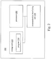
- the main network node 102 may include a processor 200, a storage unit 210, and a communication interfacing unit 220.
- the processor 200, the storage unit 210, and the communication interfacing unit 220 are electrically connected to each other.
- the processor 200 may be a microprocessor or an Application Specific Integrated Circuit (ASIC).
- the storage unit 210 may be any data storage device that can store a program code (e.g., the program 214) which can be accessed and executed by the processor 200.
- the storage unit 210 may be, for example, a read-only memory (ROM), a magnetic tape, a hard disk, and an optical data storage device, but is not limited in this regard.
- the communication interfacing unit 220 may be a transceiver and is used to transmit and receive signals (e.g., messages or packets). In some embodiments, the communication interfacing unit 220 may transmit signals according to processing results of the processor 200.
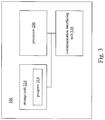
- the auxiliary network node 104 may include a processor 300, a storage unit 310, and a communication interfacing unit 320.
- the processor 300, the storage unit 310, and the communication interfacing unit 320 are electrically connected to each other.
- the processor 300 may be a microprocessor or an Application Specific Integrated Circuit (ASIC).
- the storage unit 310 may be any data storage device that can store a program code (e.g., the program 314) which can be accessed and executed by the processor 300.
- the storage unit 310 may be, for example, a read-only memory (ROM), a magnetic tape, a hard disk, and an optical data storage device, but is not limited in this regard.
- the communication interfacing unit 320 may be a transceiver and is used to transmit and receive signals (e.g., messages or packets). In some embodiments, the communication interfacing unit 320 may transmit signals according to processing results of the processor 300.
- a radio protocol architecture is provided for communications of the wireless communication system 10.
- a radio bearer can be a data radio bearer (DRB) setup for user plane data transmission and/or reception or a signaling radio bearer (SRB) setup for control plane data transmission and/or reception.
- DRB configuration includes DRB identity, EPS bearer identity, PDCP configuration (e.g. header compression configuration), RLC configuration, logical channel identity and logical channel configuration (e.g. priority and logical channel group).
- a SRB configuration includes SRB identity, RLC configuration and logical channel configuration.
- MCG bearer MCG bearer
- SCG bearer SCG bearer
- split bearer there are three types of radio bearers.
- the MCG bearer utilizes radio protocols only located in the MeNB to use MeNB resources only.
- the SCG bearer utilizes radio protocols only located in the SeNB to use SeNB resources.
- the Split bearer utilizes radio protocols located in both the MeNB and the SeNB to use both MeNB and SeNB resources.
- a DRB can be an MCG bearer, an SCG bearer, or a split bearer.
- a SRB can be an MCG bearer, an SCG bearer, or a split bearer.
- the main network node 102 is configured for communicating with a communication device 20 via an RRC connection and at least one first RB with a MCG bearer type, to provide a network service.
- the main network node 102 requests the auxiliary network node 104 to establish at least one second RB with a SCG bearer type between the communication device 20 and an auxiliary network node 104, so that the auxiliary network node 104 communicates with the communication device 20 via the at least one second RB.
- the main network node 102 may further release the RRC connection, one of the at least one first RB, and/or one of the at least one second RB.
- Fig. 4 illustrates a method 40 including operations of the wireless communication system 10 according to one embodiment of the present disclosure.
- the processor 200 of the main network node 102 controls the communication interfacing unit 220 to establish an RRC connection between the communication device 20 and the main network node 102.
- the processor 200 of the main network node 102 controls the communication interfacing unit 220 to establish at least one first RB with an MCG bearer type between the communication device 20 and the main network node 102. After the RRC connection and the at least one first RB are established, the processor 200 utilizes the communication interfacing unit 220 to communicate with the communication device 20 via the RRC connection and the at least one first RB.
- the processor 200 of the main network node 102 controls the communication interfacing unit 220 to establish at least one second RB with an SCG bearer type between the communication device 20 and the auxiliary network node 104.
- step S4 it is determined whether a first condition has been met for a first time period.
- the first condition is that all of downlink data in all of at least one downlink buffer corresponding to one of the at least one second RB is successfully transmitted or all of the at least one downlink buffer corresponding to the one of the at least one second RB is empty, and the auxiliary network node 104 does not receive any request for an uplink grant allocation from the communication device 20. If so, the one of the at least one second RB is released (step S5). If not, step S4 is continuously performed.
- the first time period is a predetermined time period.
- the processor 300 may control the communication interfacing unit 320 to send a starting signal to the main network node 102 when the auxiliary network node 104 determines the first condition is met.
- the processor 200 of the main network node 102 may start the first timer in response of receiving the starting signal transmitted from the auxiliary network node 104.
- the processor 300 may control the communication interfacing unit 320 to send a stop/restart signal to the main network node 102 to make the processor 200 of the main network node 102 stop or restart the first timer in response of receiving the first stop/restart signal.
- the second condition is that new downlink data enters the at least one downlink buffer corresponding to the one of the at least one second RB or receives a request for an uplink grant allocation from the communication device 20.
- the processor 200 of the main network node 102 may release the one of the at least one second RB (operation S5).
- the processor 200 may perform an MeNB initiated SeNB Modification procedure defined in a file of 3GPP TS 36.300 v12.3.0 to release the one of the at least one second RB described above.
- the processor 200 may perform an MeNB initiated SeNB Release procedure defined in the file of 3GPP TS 36.300 v12.3.0 to release the one of the at least one second RB.
- the processor 300 in the auxiliary network node 104 may start the first timer with the first time period when the auxiliary network node 104 determines the first condition is met.
- the processor 300 may stop or restart the first timer.
- the processor 300 may release the one of the at least one second RB (operation S5).
- the first time period may be sent by the main network node 102 or a core network to the auxiliary network node 104 or predetermined by the auxiliary network node 104.
- the processor 300 may perform an SeNB initiated SeNB Modification procedure defined in the file of 3GPP TS 36.300 v12.3.0 to release the one of the at least one second RB described above.
- the processor 300 may perform an SeNB initiated SeNB Release procedure defined in the file of 3GPP TS 36.300 v12.3.0 to release the one of the at least one second RB.
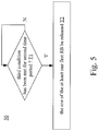
- Fig. 5 illustrates a method 50 including operations of the wireless communication system 10 according to one embodiment of the present disclosure.
- an RRC connection and at least one first RB with an MCG bearer type are established between the communication device 20 and the main network node 102, and the processor 200 can utilize the communication interfacing unit 220 to communicate with the communication device 20 via the RRC connection and the at least one first RB.
- the processor 200 of the main network node 102 determines whether a third condition has been met for a second time period.
- the third condition is that all of downlink data in all of at least one downlink buffer corresponding to one of the at least one first RB is successfully transmitted or all of the at least one downlink buffer corresponding to the one of the at least one first RB is empty, and the main network node 102 does not receive any request for an uplink grant allocation from the communication device 20. If so, the one of the at least one first RB is released (step T2). If not, step T1 is continuously performed.
- the processor 200 may transmit an RRCConnectionReconfiguration message to the communication device 20 to release the one of the at least one first RB.
- the second time period is a predetermined time period. In one embodiment, the second time period may be same as or different from the first time period described above.
- the processor 200 may start a second timer with the second time period when the main network node 102 determines the third condition is met.
- the processor 200 may stop or restart the second timer.
- the fourth condition is that new downlink data enters the at least one downlink buffer corresponding to the one of the at least one first RB or receives a request for an uplink grant allocation.
- the processor 200 may release the one of the at least one first RB (operation T2).
- Fig. 6 illustrates a method 60 including operations of the wireless communication system 10 according to one embodiment of the present disclosure.
- an RRC connection and at least one first RB with an MCG bearer type are established between the communication device 20 and the main network node 102, and the processor 200 can utilize the communication interfacing unit 220 to communicate with the communication device 20 via the RRC connection and the at least one first RB.
- the processor 200 of the main network node 102 determines whether a fifth condition is met and, for a third time period, a sixth condition has been met.
- the fifth condition is that no second RB with an SCG bearer type is configured between the communication device 20 and the auxiliary network node 104 (e.g., all of the at least one second RB between the communication device 20 and the auxiliary network node 104 as described above is released or has not been established yet).
- the sixth condition is that all of downlink data in all of at least one downlink buffer corresponding to all of the at least one first RB is successfully transmitted or all of the at least one downlink buffer corresponding to all of the at least one first RB is empty, and the main network node 102 does not receive any request for an uplink grant allocation from the communication device 20. If so, the RRC connection is released (step R2). If not, step R1 is continuously performed.
- the third time period is a predetermined time period. In one embodiment, the third time period may be same as or different from the second time period and the first time period described above. In one embodiment, the processor 200 may transmit an RRCConnectionRelease message to the communication device 20 to release the RRC connection.
- the processor 200 may start a third timer with the third time period when the main network node 102 determines the sixth condition is met.
- the processor 200 may stop or restart the third timer.
- the main network node 102 determines to establish a second RB with an SCG bearer type configured between the communication device 20 and the auxiliary network node 104
- the processor 200 may stop or restart the third timer.
- the processor 200 may release the RRC connection (operation R2).
- the methods 40, 50, 60 can be combined together.
- the operations R1, R2 may be performed after operation S5 or between operations S1, S3.
- the operations T1, T2 may be performed after operation S2.
- the methods 40, 50, 60 can be performed simultaneously or the execution times thereof may at least partially overlap.
- the request for an uplink grant allocation described above may be a scheduling request or a buffer status report which indicates the communication device 20 has uplink data to transmit.
- the buffer status report may include uplink data volume of the at least one second RB.
- the downlink buffer corresponding to a RB is configured to (temperately) store downlink data to be transmitted to the communication device 20 by the auxiliary network node 104 via the RB.
Landscapes
- Engineering & Computer Science (AREA)
- Computer Networks & Wireless Communication (AREA)
- Signal Processing (AREA)
- Mobile Radio Communication Systems (AREA)
Abstract
Description
- The present invention relates to a method used in a wireless communication system and related communication device. More particularly, the present invention relates to a method of handling radio bearer addition and release for operation of dual connectivity and related communication device. Specifically, the present invention relates to a network node and a communication method applicable to a network node.
- A long-term evolution (LTE) system supporting the 3GPP Rel-8 standard and/or the 3GPP Rel-9 standard are developed by the 3rd Generation Partnership Project (3GPP) as a successor of a universal mobile telecommunication system (UMTS) for further enhancing performance of the UMTS to satisfy increasing needs of users. In the LTE system, a radio access network known as an evolved universal terrestrial radio access network (E-UTRAN) includes multiple evolved Node-Bs (eNBs) for communicating with multiple user equipments (UEs), and communicating with a core network including a mobility management entity (MME), a serving gateway, etc., for Non-Access Stratum (NAS) control.
- An LTE-advanced (LTE-A) system, as its name implies, is an evolution of the LTE system. The LTE-A system targets faster switching between power states, improves performance at the coverage edge of an eNB, and includes advanced techniques, such as carrier aggregation (CA), coordinated multipoint transmission/reception (CoMP) or uplink (UL) multiple-input multiple-output (MIMO). For a UE and an eNB to communicate with each other in the LTE-A system, the UE and the eNB must support standards developed for the LTE-A system, such as the 3GPP Rel-10 standard or later versions.
- NTT DOCOMO ET AL, "Introduction of Dual Connectivity", RAN WG3, Shanghai, China; 30 September 2014, 3GPP DRAFT; R3-142122-36.300 CRXXXX_(REL-12)_R2-144578_INTRODUCTION OF DUAL CONNECTIVITY, 3RD GENERATION PARTNERSHIP PROJECT (3GPP), MOBILE COMPETENCE CENTRE ; 650, ROUTE DES LUCIOLES ; F-06921 SOPHIA ANTIPOLIS; FRANCE discusses aspects of Dual Connectivity.
-
AU 2013/248261 A1 - In accordance with the present invention; a network node and a method for a network node are provided as set forth in the independent claims 1 and 6. Preferred embodiments of the present invention may be gathered from the dependent claims.
- One aspect of the present disclosure is related to a network node. In accordance with one embodiment of the present disclosure, the network node includes a communication interfacing unit and a processor. The communication interfacing unit is configured for communicating with a communication device via a radio resource control (RRC) connection and at least one first radio bearer (RB) with a master cell group (MCG) bearer type. The processor is electrically connected with the communication interfacing unit. The processor is operable to perform operations including controlling the communication interfacing unit to establish at least one second RB with a secondary cell group (SCG) bearer type between the communication device and an auxiliary network node; and releasing one of the at least one second RB when it is determined that a first condition has been met for a first time period, wherein the first condition is that all of downlink data in all of at least one downlink buffer corresponding to the one of the at least one second RB is successfully transmitted or all of the at least one downlink buffer corresponding to the one of the at least one second RB is empty, and the auxiliary network node does not receive any request for an uplink grant allocation from the communication device.
- Another aspect of the present disclosure is related to a network node. In accordance with one embodiment of the present disclosure, the network node includes a communication interfacing unit and a processor. The communication interfacing unit is configured for communicating with a communication device via an RRC connection and at least one RB with an MCG bearer type. The processor is electrically connected with the communication interfacing unit. The processor is operable to perform operations including releasing the RRC connection when the processor determines that a first condition is met and for a first time period, a second condition has been met, wherein the first condition is that no second RB with an SCG bearer type is configured between the communication device and an auxiliary network node, and the second condition is that all of downlink data in all of at least one downlink buffer corresponding to all of the at least one first RB is successfully transmitted or all of the at least one downlink buffer corresponding to all of the at least one first RB is empty, and the network node does not receive any request for an uplink grant allocation from the communication device.
- Through an application of one embodiment described above, one of the at least one second RB can be released without affecting the data transmission of the communication device.
- The invention can be more fully understood by reading the following detailed description of the embodiment, with reference made to the accompanying drawings as follows:
-
Fig. 1 is a schematic diagram of a wireless communication system according to one embodiment of the present disclosure. -
Fig. 2 is a schematic block diagram of a main network node according to one embodiment of the present disclosure. -
Fig. 3 is a schematic block diagram of an auxiliary network node according to one embodiment of the present disclosure. -
Fig. 4 is a flowchart of a method of a wireless communication system according to one embodiment of the present disclosure. -
Fig. 5 is a flowchart of a method of a wireless communication system according to another embodiment of the present disclosure. -
Fig. 6 is a flowchart of a method of a wireless communication system according to still another embodiment of the present disclosure. - A UE in dual connectivity (i.e., a mode of a UE in RRC_CONNECTED) is configured with a Master Cell Group (MCG) and a Secondary Cell Group (SCG). In dual connectivity, a Master Cell Group is a group of serving cells associated with Master eNB (MeNB), including a Primary Cell (PCell) and optionally one or more Secondary Cells (SCells). In dual connectivity, the MeNB is an eNB which communicates with at least one MME and the UE. A Secondary Cell Group is a group of serving cells associated with a Secondary eNB (SeNB), including a Primary SCell (PSCell) and optionally one or more SCells. The SeNB is an eNB that provides additional radio resources for the UE. The SeNB is different from the MeNB.
- When the UE is in dual connectivity, the UE performs transmissions and/or receptions (e.g., of data, packets, messages and/or control information) via both the MeNB and the SeNB. E-UTRAN supports dual connectivity operation whereby a UE with multiple receivers (RXs)/ transmitters (TXs) in RRC_CONNECTED status is configured to utilize radio resources provided by two distinct schedulers, located in two eNBs.
- When an UE in idle mode has data to send, the UE initiates a radion resource control (RRC) connection establishment to a first eNB (i.e. MeNB) to request entering RRC connected mode. The first eNB configures the UE an RRC connection and a first data radio bearer (DRB) to transmit and/or receive data. The first eNB further configures the UE a second DRB to transmit and/or receive data. The first DRB is an MCG bearer and the second DRB is an SCG bearer. In other words, the UE transmits and/or receives data via the second DRB to/from a second eNB (i.e. SeNB) while transmitting and/or receiving data via the first DRB to/from the first eNB.
-
Fig. 1 is a schematic diagram of awireless communication system 10 according to an embodiment of the present disclosure. Thewireless communication system 10 includes a communication device (e.g., a user equipment (UE) as described above) 20, a main network node (e.g., a macro cell base station (BS) or an MeNB) 102, and an auxiliary network node (e.g., a low-power BS or an SeNB) 104. InFig. 1 , thecommunication device 20, themain network node 102 and theauxiliary network node 104 and are simply utilized for illustrating the structure of thewireless communication system 10. Practically, themain network node 102 and/or theauxiliary network node 104 can be eNBs or relay stations in an evolved UTRAN (E-UTRAN) or fifth generation (5G) base stations. In addition, theauxiliary network node 104 may be a pico cell BS or a femto cell BS. InFig. 1 , theauxiliary network node 104 is in a coverage area 102ca of themain network node 102. In another example, theauxiliary network node 104 may be outside the coverage area 102ca of the macro BS 102, but the coverage areas 104ca, 102ca of the auxiliary network node 104 (e.g., a low-power BS) and the main network node 102 (e.g., a macro BS) are partly overlapped. - As shown in
Fig. 1 , thecommunication device 20 is in coverage areas 102ca, 104ca of themain network node 102 and the auxiliarynetwork node BS 104. Thecommunication device 20 communicates with themain network node 102 and theauxiliary network node 104 at the same time. That is, thecommunication device 104 performs a transmission/reception via both a cell of themain network node 102 and a cell of theauxiliary network node 102. Thecommunication device 20 can be a machine type communication (MTC) device, a mobile phone, a laptop, a tablet computer, an electronic book, a portable computer system, a vehicle or an airplane. In addition, themain network node 102/theauxiliary network node 104 and thecommunication device 20 can be seen as a transmitter or a receiver according to direction. For example, for an uplink (UL), thecommunication device 20 is the transmitter and themain network node 102/theauxiliary network node 104 is the receiver, and for a downlink (DL), themain network node 102/theauxiliary network node 104 is the transmitter and thecommunication device 20 is the receiver. - Reference is made to
Fig. 2 , which is a schematic diagram of themain network node 102 according to one embodiment of the present disclosure. Themain network node 102 may include aprocessor 200, astorage unit 210, and acommunication interfacing unit 220. In one embodiment, theprocessor 200, thestorage unit 210, and thecommunication interfacing unit 220 are electrically connected to each other. Theprocessor 200 may be a microprocessor or an Application Specific Integrated Circuit (ASIC). Thestorage unit 210 may be any data storage device that can store a program code (e.g., the program 214) which can be accessed and executed by theprocessor 200. In one embodiment, thestorage unit 210 may be, for example, a read-only memory (ROM), a magnetic tape, a hard disk, and an optical data storage device, but is not limited in this regard. In one embodiment, thecommunication interfacing unit 220 may be a transceiver and is used to transmit and receive signals (e.g., messages or packets). In some embodiments, thecommunication interfacing unit 220 may transmit signals according to processing results of theprocessor 200. - Reference is made to
Fig. 3 , which is a schematic diagram of theauxiliary network node 104 according to one embodiment of the present disclosure. Theauxiliary network node 104 may include aprocessor 300, astorage unit 310, and acommunication interfacing unit 320. Theprocessor 300, thestorage unit 310, and thecommunication interfacing unit 320 are electrically connected to each other. In one embodiment, theprocessor 300 may be a microprocessor or an Application Specific Integrated Circuit (ASIC). In one embodiment, thestorage unit 310 may be any data storage device that can store a program code (e.g., the program 314) which can be accessed and executed by theprocessor 300. In one embodiment, thestorage unit 310 may be, for example, a read-only memory (ROM), a magnetic tape, a hard disk, and an optical data storage device, but is not limited in this regard. In one embodiment, thecommunication interfacing unit 320 may be a transceiver and is used to transmit and receive signals (e.g., messages or packets). In some embodiments, thecommunication interfacing unit 320 may transmit signals according to processing results of theprocessor 300. - In one embodiment, a radio protocol architecture is provided for communications of the
wireless communication system 10. In the radio protocol architecture, a radio bearer (RB) can be a data radio bearer (DRB) setup for user plane data transmission and/or reception or a signaling radio bearer (SRB) setup for control plane data transmission and/or reception. A DRB configuration includes DRB identity, EPS bearer identity, PDCP configuration (e.g. header compression configuration), RLC configuration, logical channel identity and logical channel configuration (e.g. priority and logical channel group). A SRB configuration includes SRB identity, RLC configuration and logical channel configuration. In dual connectivity, there are three types of radio bearers: MCG bearer, SCG bearer, and split bearer. The MCG bearer utilizes radio protocols only located in the MeNB to use MeNB resources only. The SCG bearer utilizes radio protocols only located in the SeNB to use SeNB resources. The Split bearer utilizes radio protocols located in both the MeNB and the SeNB to use both MeNB and SeNB resources. A DRB can be an MCG bearer, an SCG bearer, or a split bearer. A SRB can be an MCG bearer, an SCG bearer, or a split bearer. - In one embodiment, the
main network node 102 is configured for communicating with acommunication device 20 via an RRC connection and at least one first RB with a MCG bearer type, to provide a network service. Themain network node 102 requests theauxiliary network node 104 to establish at least one second RB with a SCG bearer type between thecommunication device 20 and anauxiliary network node 104, so that theauxiliary network node 104 communicates with thecommunication device 20 via the at least one second RB. In addition, themain network node 102 may further release the RRC connection, one of the at least one first RB, and/or one of the at least one second RB. - It should be noted that in the following operations, no particular sequence is required unless otherwise specified. Moreover, the following operations also may be performed simultaneously or the execution times thereof may at least partially overlap.
-
Fig. 4 illustrates amethod 40 including operations of thewireless communication system 10 according to one embodiment of the present disclosure. - In operation S1, the
processor 200 of themain network node 102 controls thecommunication interfacing unit 220 to establish an RRC connection between thecommunication device 20 and themain network node 102. - In operation S2, the
processor 200 of themain network node 102 controls thecommunication interfacing unit 220 to establish at least one first RB with an MCG bearer type between thecommunication device 20 and themain network node 102. After the RRC connection and the at least one first RB are established, theprocessor 200 utilizes thecommunication interfacing unit 220 to communicate with thecommunication device 20 via the RRC connection and the at least one first RB. - In operation S3, the
processor 200 of themain network node 102 controls thecommunication interfacing unit 220 to establish at least one second RB with an SCG bearer type between thecommunication device 20 and theauxiliary network node 104. - In operation S4, it is determined whether a first condition has been met for a first time period. The first condition is that all of downlink data in all of at least one downlink buffer corresponding to one of the at least one second RB is successfully transmitted or all of the at least one downlink buffer corresponding to the one of the at least one second RB is empty, and the
auxiliary network node 104 does not receive any request for an uplink grant allocation from thecommunication device 20. If so, the one of the at least one second RB is released (step S5). If not, step S4 is continuously performed. - In one embodiment, the first time period is a predetermined time period. In one embodiment, the
processor 300 may control thecommunication interfacing unit 320 to send a starting signal to themain network node 102 when theauxiliary network node 104 determines the first condition is met. Theprocessor 200 of themain network node 102 may start the first timer in response of receiving the starting signal transmitted from theauxiliary network node 104. When theauxiliary network node 104 determines a second condition is met, theprocessor 300 may control thecommunication interfacing unit 320 to send a stop/restart signal to themain network node 102 to make theprocessor 200 of themain network node 102 stop or restart the first timer in response of receiving the first stop/restart signal. The second condition is that new downlink data enters the at least one downlink buffer corresponding to the one of the at least one second RB or receives a request for an uplink grant allocation from thecommunication device 20. When the first timer expires, theprocessor 200 of themain network node 102 may release the one of the at least one second RB (operation S5). - In some embodiments of operation S5, when more than one second RBs are configured between the
auxiliary network node 104 and thecommunication device 20, theprocessor 200 may perform an MeNB initiated SeNB Modification procedure defined in a file of 3GPP TS 36.300 v12.3.0 to release the one of the at least one second RB described above. In some embodiments, when there is only one second RB (i.e., the one of the at least one second RB) configured between theauxiliary network node 104 and thecommunication device 20, theprocessor 200 may perform an MeNB initiated SeNB Release procedure defined in the file of 3GPP TS 36.300 v12.3.0 to release the one of the at least one second RB. - In an alternative embodiment, in operation S4, the
processor 300 in theauxiliary network node 104 may start the first timer with the first time period when theauxiliary network node 104 determines the first condition is met. When theauxiliary network node 104 determines the second condition is met, theprocessor 300 may stop or restart the first timer. When the first timer expires, theprocessor 300 may release the one of the at least one second RB (operation S5). The first time period may be sent by themain network node 102 or a core network to theauxiliary network node 104 or predetermined by theauxiliary network node 104. - In some embodiments of operation S5, when more than one second RBs are configured between the
auxiliary network node 104 and thecommunication device 20, theprocessor 300 may perform an SeNB initiated SeNB Modification procedure defined in the file of 3GPP TS 36.300 v12.3.0 to release the one of the at least one second RB described above. In some embodiments, when there is only one second RB (i.e., the one of the at least one second RB) configured between theauxiliary network node 104 and thecommunication device 20, theprocessor 300 may perform an SeNB initiated SeNB Release procedure defined in the file of 3GPP TS 36.300 v12.3.0 to release the one of the at least one second RB. -
Fig. 5 illustrates amethod 50 including operations of thewireless communication system 10 according to one embodiment of the present disclosure. - In this operative example, an RRC connection and at least one first RB with an MCG bearer type are established between the
communication device 20 and themain network node 102, and theprocessor 200 can utilize thecommunication interfacing unit 220 to communicate with thecommunication device 20 via the RRC connection and the at least one first RB. - In operation T1, the
processor 200 of themain network node 102 determines whether a third condition has been met for a second time period. The third condition is that all of downlink data in all of at least one downlink buffer corresponding to one of the at least one first RB is successfully transmitted or all of the at least one downlink buffer corresponding to the one of the at least one first RB is empty, and themain network node 102 does not receive any request for an uplink grant allocation from thecommunication device 20. If so, the one of the at least one first RB is released (step T2). If not, step T1 is continuously performed. - In one embodiment, the
processor 200 may transmit an RRCConnectionReconfiguration message to thecommunication device 20 to release the one of the at least one first RB. In one embodiment, the second time period is a predetermined time period. In one embodiment, the second time period may be same as or different from the first time period described above. - In one embodiment, in operation T1 described above, the
processor 200 may start a second timer with the second time period when themain network node 102 determines the third condition is met. When themain network node 102 determines a fourth condition is met, theprocessor 200 may stop or restart the second timer. The fourth condition is that new downlink data enters the at least one downlink buffer corresponding to the one of the at least one first RB or receives a request for an uplink grant allocation. When the second timer expires, theprocessor 200 may release the one of the at least one first RB (operation T2). -
Fig. 6 illustrates amethod 60 including operations of thewireless communication system 10 according to one embodiment of the present disclosure. - In this operative example, an RRC connection and at least one first RB with an MCG bearer type are established between the
communication device 20 and themain network node 102, and theprocessor 200 can utilize thecommunication interfacing unit 220 to communicate with thecommunication device 20 via the RRC connection and the at least one first RB. - In operation R1, the
processor 200 of themain network node 102 determines whether a fifth condition is met and, for a third time period, a sixth condition has been met. The fifth condition is that no second RB with an SCG bearer type is configured between thecommunication device 20 and the auxiliary network node 104 (e.g., all of the at least one second RB between thecommunication device 20 and theauxiliary network node 104 as described above is released or has not been established yet). The sixth condition is that all of downlink data in all of at least one downlink buffer corresponding to all of the at least one first RB is successfully transmitted or all of the at least one downlink buffer corresponding to all of the at least one first RB is empty, and themain network node 102 does not receive any request for an uplink grant allocation from thecommunication device 20. If so, the RRC connection is released (step R2). If not, step R1 is continuously performed. - In one embodiment, the third time period is a predetermined time period. In one embodiment, the third time period may be same as or different from the second time period and the first time period described above. In one embodiment, the
processor 200 may transmit an RRCConnectionRelease message to thecommunication device 20 to release the RRC connection. - In one embodiment, in operation R1 described above, the
processor 200 may start a third timer with the third time period when themain network node 102 determines the sixth condition is met. - When the
main network node 102 determines new downlink data enters one of the at least one downlink buffer corresponding to all of the at least one first RB or receives a request for an uplink grant allocation from thecommunication device 20, theprocessor 200 may stop or restart the third timer. When themain network node 102 determines to establish a second RB with an SCG bearer type configured between thecommunication device 20 and theauxiliary network node 104, theprocessor 200 may stop or restart the third timer. When the fifth condition is met and the third timer expires, theprocessor 200 may release the RRC connection (operation R2). - Noted that, in some embodiments, the
methods methods - Note that, in the embodiments described above, the request for an uplink grant allocation described above may be a scheduling request or a buffer status report which indicates the
communication device 20 has uplink data to transmit. The buffer status report may include uplink data volume of the at least one second RB. In the description above, the downlink buffer corresponding to a RB is configured to (temperately) store downlink data to be transmitted to thecommunication device 20 by theauxiliary network node 104 via the RB. - Although the present invention has been described in considerable detail with reference to certain embodiments thereof, other embodiments are possible. Therefore, the scope of the appended claims should not be limited to the description of the embodiments contained herein.
Claims (10)
- A network node comprising:a communication interfacing unit configured for communicating with a communication device via a radio resource control, RRC, connection and at least one radio bearer, RB, with a master cell group, MCG, bearer type; anda processor electrically connected with the communication interfacing unit, the processor operable to perform operations comprising:releasing the RRC connection when the processor determines that a first condition is met and for a first time period, a second condition has been met, wherein the first condition is that no second RB with a secondary cell group, SCG, bearer type is configured between the communication device and an auxiliary network node, and the second condition is that all of downlink data in all of at least one downlink buffer corresponding to all of at least one first RB is successfully transmitted or all of the at least one downlink buffer corresponding to all of the at least one first RB is empty, and the network node does not receive any request for an uplink grant allocation from the communication device.
- The network node as claimed in claim 1, wherein releasing the RRC connection when the network node determines that the first condition is met and for the first time period, the second condition has been met comprising:starting a timer with the first time period when the second condition is met; andreleasing the RRC connection when the first condition is met and the timer expires.
- The network node as claimed in claim 2, wherein the processor is further operable for:stopping or restarting the timer when new downlink data enters the at least one downlink buffer corresponding to all of the at least one first RB.
- The network node as claimed in claim 2, wherein the processor is further operable for:stopping or restarting the timer when the network node receives a request for an uplink grant allocation.
- The network node as claimed in claim 1, wherein the processor is further operable for:releasing one of the at least one first RB when the processor determines that a third condition has been met for a second time period, wherein the third condition is that all of the downlink data in at least one downlink buffer corresponding to the one of the at least one first RB is successfully transmitted or the at least one downlink buffer corresponding to the one of the at least one first RB is empty, and the network node does not receive any request for an uplink grant allocation from the communication device.
- A communication method applicable to a network node, the method comprising:the network node communicating with a communication device via a radio resource control, RRC, connection and at least one radio bearer, RB, with a master cell group, MCG, bearer type; andthe network node releasing the RRC connection when a first condition is met for a first time period, a second condition has been met, wherein the first condition is that no second RB with a secondary cell group, SCG, bearer type is configured between the communication device and an auxiliary network node, and the second condition is that all of downlink data in all of at least one downlink buffer corresponding to all of at least one first RB is successfully transmitted or all of the at least one downlink buffer corresponding to all of the at least one first RB is empty, and the network node does not receive any request for an uplink grant allocation from the communication device.
- The communication method of claim 6, wherein the network node releasing the RRC connection when the network node determines that the first condition is met for the first time period, the second condition has been met comprising:the network node starting a timer with the first time period when the second condition is met; andthe network node releasing the RRC connection when the first condition is met and the timer expires.
- The communication method of claim 7, further comprising:the network node stopping or restarting the timer when new downlink data enters the at least one downlink buffer corresponding to all of the at least one first RB.
- The communication method of claim 7, further comprising:the network node stopping or restarting the timer when the network node receives a request for an uplink grant allocation.
- The communication method of claim 6, further comprising:the network node releasing one of the at least one first RB when a third condition has been met for a second time period, wherein the third condition is that all of the downlink data in at least one downlink buffer corresponding to the one of the at least one first RB is successfully transmitted or the at least one downlink buffer corresponding to the one of the at least one first RB is empty, and the network node does not receive any request for an uplink grant allocation from the communication device.
Applications Claiming Priority (2)
| Application Number | Priority Date | Filing Date | Title |
|---|---|---|---|
| US201462058676P | 2014-10-02 | 2014-10-02 | |
| EP15188168.7A EP3002985B1 (en) | 2014-10-02 | 2015-10-02 | Method and apparatus for handling release of simultaneous communication with multiple base stations and related communication device |
Related Parent Applications (2)
| Application Number | Title | Priority Date | Filing Date |
|---|---|---|---|
| EP15188168.7A Division EP3002985B1 (en) | 2014-10-02 | 2015-10-02 | Method and apparatus for handling release of simultaneous communication with multiple base stations and related communication device |
| EP15188168.7A Division-Into EP3002985B1 (en) | 2014-10-02 | 2015-10-02 | Method and apparatus for handling release of simultaneous communication with multiple base stations and related communication device |
Publications (2)
| Publication Number | Publication Date |
|---|---|
| EP3174354A1 true EP3174354A1 (en) | 2017-05-31 |
| EP3174354B1 EP3174354B1 (en) | 2018-09-19 |
Family
ID=54291062
Family Applications (2)
| Application Number | Title | Priority Date | Filing Date |
|---|---|---|---|
| EP15188168.7A Active EP3002985B1 (en) | 2014-10-02 | 2015-10-02 | Method and apparatus for handling release of simultaneous communication with multiple base stations and related communication device |
| EP17150475.6A Active EP3174354B1 (en) | 2014-10-02 | 2015-10-02 | Method and apparatus for handling rrc release during dual connectivity communication with multiple base stations and related communication device |
Family Applications Before (1)
| Application Number | Title | Priority Date | Filing Date |
|---|---|---|---|
| EP15188168.7A Active EP3002985B1 (en) | 2014-10-02 | 2015-10-02 | Method and apparatus for handling release of simultaneous communication with multiple base stations and related communication device |
Country Status (4)
| Country | Link |
|---|---|
| US (1) | US9974114B2 (en) |
| EP (2) | EP3002985B1 (en) |
| JP (2) | JP6265504B2 (en) |
| CN (2) | CN105491680B (en) |
Families Citing this family (4)
| Publication number | Priority date | Publication date | Assignee | Title |
|---|---|---|---|---|
| EP3456143A1 (en) * | 2016-05-13 | 2019-03-20 | Intel IP Corporation | Rrc signaling for dual connectivity |
| US9906991B1 (en) * | 2016-09-29 | 2018-02-27 | Intel IP Corporation | Cellular telephone network to narrow band—internet of things network switching method and apparatus |
| CN108633018B (en) * | 2017-03-23 | 2024-02-02 | 华为技术有限公司 | Configuration method, device and system |
| EP4442013A1 (en) * | 2022-01-06 | 2024-10-09 | Google Llc | Configuring resources for multicast and/or broadcast services in a distributed base station architecture |
Citations (2)
| Publication number | Priority date | Publication date | Assignee | Title |
|---|---|---|---|---|
| US20050063304A1 (en) * | 2002-05-07 | 2005-03-24 | Nokia Corporation | Release timer for NRT connection in mobile communication network |
| AU2013248261A1 (en) | 2009-11-23 | 2013-11-14 | Blackberry Limited | Method and apparatus for state/mode transitioning |
Family Cites Families (12)
| Publication number | Priority date | Publication date | Assignee | Title |
|---|---|---|---|---|
| FI110352B (en) | 2000-02-24 | 2002-12-31 | Nokia Corp | Method and arrangement to optimize the re-establishment of connections in a cellular radio system that supports real-time and non-real-time communications |
| SG155195A1 (en) * | 2004-04-30 | 2009-09-30 | Interdigital Tech Corp | Method and apparatus for minimizing redundant enhanced uplink allocation requests |
| SG137794A1 (en) | 2006-05-17 | 2007-12-28 | Research In Motion Ltd | Method and system for signaling release cause indication in a umts network |
| CN102594435B (en) * | 2011-01-11 | 2014-11-05 | 华为技术有限公司 | Relay node subframe configuration method, device and communication system |
| KR101995293B1 (en) | 2011-02-21 | 2019-07-02 | 삼성전자 주식회사 | Method and appratus of activating or deactivating secondary carriers in time division duplex mobile communication system using carrier aggregation |
| CN103139931B (en) * | 2011-12-02 | 2017-11-14 | 株式会社Ntt都科摩 | A kind of method, apparatus for controlling wireless heterogeneous networks connection status and base station |
| US9832672B2 (en) * | 2012-04-27 | 2017-11-28 | Mitsubishi Electric Corporation | Communication system |
| JP2014022895A (en) | 2012-07-17 | 2014-02-03 | Sharp Corp | Radio communication system, radio communication method, mobile station device, base station device, program, and recording medium |
| KR101708574B1 (en) * | 2012-08-23 | 2017-02-20 | 인터디지탈 패튼 홀딩스, 인크 | Operating with multiple schedulers in a wireless system |
| KR101670311B1 (en) * | 2013-01-30 | 2016-10-28 | 이노베이티브 소닉 코포레이션 | Method and apparatus for handling inter-node connectivity in a wireless communication system |
| US9538575B2 (en) * | 2014-01-30 | 2017-01-03 | Sharp Kabushiki Kaisha | Systems and methods for dual-connectivity operation |
| CN103945408A (en) * | 2014-03-14 | 2014-07-23 | 电信科学技术研究院 | Wireless link monitoring method and equipment |
-
2015
- 2015-09-30 CN CN201510639326.3A patent/CN105491680B/en active Active
- 2015-09-30 CN CN201811010078.6A patent/CN109041271B/en active Active
- 2015-10-01 US US14/872,161 patent/US9974114B2/en active Active
- 2015-10-02 EP EP15188168.7A patent/EP3002985B1/en active Active
- 2015-10-02 JP JP2015196881A patent/JP6265504B2/en active Active
- 2015-10-02 EP EP17150475.6A patent/EP3174354B1/en active Active
-
2017
- 2017-08-09 JP JP2017154661A patent/JP6464537B2/en active Active
Patent Citations (2)
| Publication number | Priority date | Publication date | Assignee | Title |
|---|---|---|---|---|
| US20050063304A1 (en) * | 2002-05-07 | 2005-03-24 | Nokia Corporation | Release timer for NRT connection in mobile communication network |
| AU2013248261A1 (en) | 2009-11-23 | 2013-11-14 | Blackberry Limited | Method and apparatus for state/mode transitioning |
Non-Patent Citations (3)
| Title |
|---|
| AWARD SOLUTIONS, INC: "User Inactivity Monitoring", 29 April 2013 (2013-04-29), XP002752951, Retrieved from the Internet <URL:http://lteuniversity.com/ask_the_expert/f/59/t/3276.aspx> [retrieved on 20160114] * |
| NTT DOCOMO ET AL.: "3GPP DRAFT; R3-142122-36.300 CRXXXX_(REL-12)_R2-144578_INTRODUCTION OF DUAL CONNECTIVITY, 3RD GENERATION PARTNERSHIP PROJECT (3GPP", 30 September 2014, MOBILE COMPETENCE CENTRE, article "Introduction of Dual Connectivity" |
| NTT DOCOMO ET AL: "Introduction of Dual Connectivity", vol. RAN WG3, no. Shanghai, China; 20141006 - 20141010, 30 September 2014 (2014-09-30), XP050871017, Retrieved from the Internet <URL:http://www.3gpp.org/ftp/tsg_ran/WG3_Iu/TSGR3_85bis/Docs/> [retrieved on 20140930] * |
Also Published As
| Publication number | Publication date |
|---|---|
| JP2016076930A (en) | 2016-05-12 |
| CN109041271A (en) | 2018-12-18 |
| CN105491680A (en) | 2016-04-13 |
| EP3002985B1 (en) | 2018-08-29 |
| CN105491680B (en) | 2019-04-19 |
| US20160100418A1 (en) | 2016-04-07 |
| US9974114B2 (en) | 2018-05-15 |
| JP6265504B2 (en) | 2018-01-24 |
| EP3002985A1 (en) | 2016-04-06 |
| JP2017225168A (en) | 2017-12-21 |
| JP6464537B2 (en) | 2019-02-06 |
| EP3174354B1 (en) | 2018-09-19 |
| CN109041271B (en) | 2020-11-03 |
Similar Documents
| Publication | Publication Date | Title |
|---|---|---|
| US9504052B2 (en) | Device and method of handling communication operation with multiple base stations | |
| EP3041310B1 (en) | Methods of handling simultaneous communications and related communication devices | |
| EP3244672B1 (en) | Handling state change of radio resource control | |
| EP2991438B1 (en) | Method for simultaneous communications with multiple base stations | |
| CN105794303B (en) | Terminal device, base station device, and communication control method | |
| EP3439221B1 (en) | Device and method of handling carrier aggregation and dual connectivity | |
| EP3089490B1 (en) | Efficient signaling of capabilities of a terminal communicating with a plurality of cell groups | |
| EP3236704B1 (en) | Device and method of handling device-to-device communication | |
| US9774427B2 (en) | Method of handling uplink/downlink configurations for time-division duplexing system and related communication device | |
| WO2014166106A1 (en) | Pdcp operation for dual connection | |
| EP2955961B1 (en) | Devices for handling measurement configuration | |
| US20250016861A1 (en) | Method and apparatus for handling connection with multi-sim | |
| EP3174354B1 (en) | Method and apparatus for handling rrc release during dual connectivity communication with multiple base stations and related communication device | |
| US20240072984A1 (en) | Methods and apparatuses of enhanced mechanism for deactivated or dormant sn |
Legal Events
| Date | Code | Title | Description |
|---|---|---|---|
| PUAI | Public reference made under article 153(3) epc to a published international application that has entered the european phase |
Free format text: ORIGINAL CODE: 0009012 |
|
| 17P | Request for examination filed |
Effective date: 20170105 |
|
| AC | Divisional application: reference to earlier application |
Ref document number: 3002985 Country of ref document: EP Kind code of ref document: P |
|
| AK | Designated contracting states |
Kind code of ref document: A1 Designated state(s): AL AT BE BG CH CY CZ DE DK EE ES FI FR GB GR HR HU IE IS IT LI LT LU LV MC MK MT NL NO PL PT RO RS SE SI SK SM TR |
|
| AX | Request for extension of the european patent |
Extension state: BA ME |
|
| GRAP | Despatch of communication of intention to grant a patent |
Free format text: ORIGINAL CODE: EPIDOSNIGR1 |
|
| RIC1 | Information provided on ipc code assigned before grant |
Ipc: H04W 72/04 20090101AFI20180309BHEP |
|
| INTG | Intention to grant announced |
Effective date: 20180328 |
|
| GRAS | Grant fee paid |
Free format text: ORIGINAL CODE: EPIDOSNIGR3 |
|
| GRAA | (expected) grant |
Free format text: ORIGINAL CODE: 0009210 |
|
| AC | Divisional application: reference to earlier application |
Ref document number: 3002985 Country of ref document: EP Kind code of ref document: P |
|
| AK | Designated contracting states |
Kind code of ref document: B1 Designated state(s): AL AT BE BG CH CY CZ DE DK EE ES FI FR GB GR HR HU IE IS IT LI LT LU LV MC MK MT NL NO PL PT RO RS SE SI SK SM TR |
|
| REG | Reference to a national code |
Ref country code: GB Ref legal event code: FG4D |
|
| REG | Reference to a national code |
Ref country code: CH Ref legal event code: EP |
|
| REG | Reference to a national code |
Ref country code: AT Ref legal event code: REF Ref document number: 1044828 Country of ref document: AT Kind code of ref document: T Effective date: 20181015 |
|
| REG | Reference to a national code |
Ref country code: IE Ref legal event code: FG4D |
|
| REG | Reference to a national code |
Ref country code: DE Ref legal event code: R096 Ref document number: 602015016810 Country of ref document: DE |
|
| REG | Reference to a national code |
Ref country code: NL Ref legal event code: FP |
|
| PG25 | Lapsed in a contracting state [announced via postgrant information from national office to epo] |
Ref country code: GR Free format text: LAPSE BECAUSE OF FAILURE TO SUBMIT A TRANSLATION OF THE DESCRIPTION OR TO PAY THE FEE WITHIN THE PRESCRIBED TIME-LIMIT Effective date: 20181220 Ref country code: FI Free format text: LAPSE BECAUSE OF FAILURE TO SUBMIT A TRANSLATION OF THE DESCRIPTION OR TO PAY THE FEE WITHIN THE PRESCRIBED TIME-LIMIT Effective date: 20180919 Ref country code: BG Free format text: LAPSE BECAUSE OF FAILURE TO SUBMIT A TRANSLATION OF THE DESCRIPTION OR TO PAY THE FEE WITHIN THE PRESCRIBED TIME-LIMIT Effective date: 20181219 Ref country code: SE Free format text: LAPSE BECAUSE OF FAILURE TO SUBMIT A TRANSLATION OF THE DESCRIPTION OR TO PAY THE FEE WITHIN THE PRESCRIBED TIME-LIMIT Effective date: 20180919 Ref country code: LT Free format text: LAPSE BECAUSE OF FAILURE TO SUBMIT A TRANSLATION OF THE DESCRIPTION OR TO PAY THE FEE WITHIN THE PRESCRIBED TIME-LIMIT Effective date: 20180919 Ref country code: RS Free format text: LAPSE BECAUSE OF FAILURE TO SUBMIT A TRANSLATION OF THE DESCRIPTION OR TO PAY THE FEE WITHIN THE PRESCRIBED TIME-LIMIT Effective date: 20180919 Ref country code: NO Free format text: LAPSE BECAUSE OF FAILURE TO SUBMIT A TRANSLATION OF THE DESCRIPTION OR TO PAY THE FEE WITHIN THE PRESCRIBED TIME-LIMIT Effective date: 20181219 |
|
| REG | Reference to a national code |
Ref country code: LT Ref legal event code: MG4D |
|
| PG25 | Lapsed in a contracting state [announced via postgrant information from national office to epo] |
Ref country code: LV Free format text: LAPSE BECAUSE OF FAILURE TO SUBMIT A TRANSLATION OF THE DESCRIPTION OR TO PAY THE FEE WITHIN THE PRESCRIBED TIME-LIMIT Effective date: 20180919 Ref country code: AL Free format text: LAPSE BECAUSE OF FAILURE TO SUBMIT A TRANSLATION OF THE DESCRIPTION OR TO PAY THE FEE WITHIN THE PRESCRIBED TIME-LIMIT Effective date: 20180919 Ref country code: HR Free format text: LAPSE BECAUSE OF FAILURE TO SUBMIT A TRANSLATION OF THE DESCRIPTION OR TO PAY THE FEE WITHIN THE PRESCRIBED TIME-LIMIT Effective date: 20180919 |
|
| REG | Reference to a national code |
Ref country code: AT Ref legal event code: MK05 Ref document number: 1044828 Country of ref document: AT Kind code of ref document: T Effective date: 20180919 |
|
| PG25 | Lapsed in a contracting state [announced via postgrant information from national office to epo] |
Ref country code: IS Free format text: LAPSE BECAUSE OF FAILURE TO SUBMIT A TRANSLATION OF THE DESCRIPTION OR TO PAY THE FEE WITHIN THE PRESCRIBED TIME-LIMIT Effective date: 20190119 Ref country code: ES Free format text: LAPSE BECAUSE OF FAILURE TO SUBMIT A TRANSLATION OF THE DESCRIPTION OR TO PAY THE FEE WITHIN THE PRESCRIBED TIME-LIMIT Effective date: 20180919 Ref country code: EE Free format text: LAPSE BECAUSE OF FAILURE TO SUBMIT A TRANSLATION OF THE DESCRIPTION OR TO PAY THE FEE WITHIN THE PRESCRIBED TIME-LIMIT Effective date: 20180919 Ref country code: CZ Free format text: LAPSE BECAUSE OF FAILURE TO SUBMIT A TRANSLATION OF THE DESCRIPTION OR TO PAY THE FEE WITHIN THE PRESCRIBED TIME-LIMIT Effective date: 20180919 Ref country code: AT Free format text: LAPSE BECAUSE OF FAILURE TO SUBMIT A TRANSLATION OF THE DESCRIPTION OR TO PAY THE FEE WITHIN THE PRESCRIBED TIME-LIMIT Effective date: 20180919 Ref country code: IT Free format text: LAPSE BECAUSE OF FAILURE TO SUBMIT A TRANSLATION OF THE DESCRIPTION OR TO PAY THE FEE WITHIN THE PRESCRIBED TIME-LIMIT Effective date: 20180919 Ref country code: RO Free format text: LAPSE BECAUSE OF FAILURE TO SUBMIT A TRANSLATION OF THE DESCRIPTION OR TO PAY THE FEE WITHIN THE PRESCRIBED TIME-LIMIT Effective date: 20180919 Ref country code: PL Free format text: LAPSE BECAUSE OF FAILURE TO SUBMIT A TRANSLATION OF THE DESCRIPTION OR TO PAY THE FEE WITHIN THE PRESCRIBED TIME-LIMIT Effective date: 20180919 |
|
| PG25 | Lapsed in a contracting state [announced via postgrant information from national office to epo] |
Ref country code: SK Free format text: LAPSE BECAUSE OF FAILURE TO SUBMIT A TRANSLATION OF THE DESCRIPTION OR TO PAY THE FEE WITHIN THE PRESCRIBED TIME-LIMIT Effective date: 20180919 Ref country code: PT Free format text: LAPSE BECAUSE OF FAILURE TO SUBMIT A TRANSLATION OF THE DESCRIPTION OR TO PAY THE FEE WITHIN THE PRESCRIBED TIME-LIMIT Effective date: 20190119 Ref country code: SM Free format text: LAPSE BECAUSE OF FAILURE TO SUBMIT A TRANSLATION OF THE DESCRIPTION OR TO PAY THE FEE WITHIN THE PRESCRIBED TIME-LIMIT Effective date: 20180919 |
|
| REG | Reference to a national code |
Ref country code: CH Ref legal event code: PL |
|
| REG | Reference to a national code |
Ref country code: DE Ref legal event code: R097 Ref document number: 602015016810 Country of ref document: DE |
|
| REG | Reference to a national code |
Ref country code: BE Ref legal event code: MM Effective date: 20181031 |
|
| PG25 | Lapsed in a contracting state [announced via postgrant information from national office to epo] |
Ref country code: LU Free format text: LAPSE BECAUSE OF NON-PAYMENT OF DUE FEES Effective date: 20181002 |
|
| REG | Reference to a national code |
Ref country code: IE Ref legal event code: MM4A |
|
| PLBE | No opposition filed within time limit |
Free format text: ORIGINAL CODE: 0009261 |
|
| STAA | Information on the status of an ep patent application or granted ep patent |
Free format text: STATUS: NO OPPOSITION FILED WITHIN TIME LIMIT |
|
| PG25 | Lapsed in a contracting state [announced via postgrant information from national office to epo] |
Ref country code: DK Free format text: LAPSE BECAUSE OF FAILURE TO SUBMIT A TRANSLATION OF THE DESCRIPTION OR TO PAY THE FEE WITHIN THE PRESCRIBED TIME-LIMIT Effective date: 20180919 Ref country code: MC Free format text: LAPSE BECAUSE OF FAILURE TO SUBMIT A TRANSLATION OF THE DESCRIPTION OR TO PAY THE FEE WITHIN THE PRESCRIBED TIME-LIMIT Effective date: 20180919 |
|
| 26N | No opposition filed |
Effective date: 20190620 |
|
| PG25 | Lapsed in a contracting state [announced via postgrant information from national office to epo] |
Ref country code: LI Free format text: LAPSE BECAUSE OF NON-PAYMENT OF DUE FEES Effective date: 20181031 Ref country code: CH Free format text: LAPSE BECAUSE OF NON-PAYMENT OF DUE FEES Effective date: 20181031 Ref country code: BE Free format text: LAPSE BECAUSE OF NON-PAYMENT OF DUE FEES Effective date: 20181031 |
|
| PG25 | Lapsed in a contracting state [announced via postgrant information from national office to epo] |
Ref country code: SI Free format text: LAPSE BECAUSE OF FAILURE TO SUBMIT A TRANSLATION OF THE DESCRIPTION OR TO PAY THE FEE WITHIN THE PRESCRIBED TIME-LIMIT Effective date: 20180919 Ref country code: IE Free format text: LAPSE BECAUSE OF NON-PAYMENT OF DUE FEES Effective date: 20181002 |
|
| PG25 | Lapsed in a contracting state [announced via postgrant information from national office to epo] |
Ref country code: MT Free format text: LAPSE BECAUSE OF NON-PAYMENT OF DUE FEES Effective date: 20181002 |
|
| PG25 | Lapsed in a contracting state [announced via postgrant information from national office to epo] |
Ref country code: TR Free format text: LAPSE BECAUSE OF FAILURE TO SUBMIT A TRANSLATION OF THE DESCRIPTION OR TO PAY THE FEE WITHIN THE PRESCRIBED TIME-LIMIT Effective date: 20180919 |
|
| PG25 | Lapsed in a contracting state [announced via postgrant information from national office to epo] |
Ref country code: MK Free format text: LAPSE BECAUSE OF NON-PAYMENT OF DUE FEES Effective date: 20180919 Ref country code: HU Free format text: LAPSE BECAUSE OF FAILURE TO SUBMIT A TRANSLATION OF THE DESCRIPTION OR TO PAY THE FEE WITHIN THE PRESCRIBED TIME-LIMIT; INVALID AB INITIO Effective date: 20151002 Ref country code: CY Free format text: LAPSE BECAUSE OF FAILURE TO SUBMIT A TRANSLATION OF THE DESCRIPTION OR TO PAY THE FEE WITHIN THE PRESCRIBED TIME-LIMIT Effective date: 20180919 |
|
| P01 | Opt-out of the competence of the unified patent court (upc) registered |
Effective date: 20230602 |
|
| PGFP | Annual fee paid to national office [announced via postgrant information from national office to epo] |
Ref country code: NL Payment date: 20250912 Year of fee payment: 11 |
|
| PGFP | Annual fee paid to national office [announced via postgrant information from national office to epo] |
Ref country code: GB Payment date: 20250904 Year of fee payment: 11 |
|
| PGFP | Annual fee paid to national office [announced via postgrant information from national office to epo] |
Ref country code: FR Payment date: 20250908 Year of fee payment: 11 |
|
| PGFP | Annual fee paid to national office [announced via postgrant information from national office to epo] |
Ref country code: DE Payment date: 20250902 Year of fee payment: 11 |