EP3174302A1 - System and method for dynamically optimizing video quality during video transmission - Google Patents
System and method for dynamically optimizing video quality during video transmission Download PDFInfo
- Publication number
- EP3174302A1 EP3174302A1 EP16154135.4A EP16154135A EP3174302A1 EP 3174302 A1 EP3174302 A1 EP 3174302A1 EP 16154135 A EP16154135 A EP 16154135A EP 3174302 A1 EP3174302 A1 EP 3174302A1
- Authority
- EP
- European Patent Office
- Prior art keywords
- video
- transmission parameters
- mos
- quality
- video transmission
- Prior art date
- Legal status (The legal status is an assumption and is not a legal conclusion. Google has not performed a legal analysis and makes no representation as to the accuracy of the status listed.)
- Granted
Links
Images



Classifications
-
- H—ELECTRICITY
- H04—ELECTRIC COMMUNICATION TECHNIQUE
- H04N—PICTORIAL COMMUNICATION, e.g. TELEVISION
- H04N21/00—Selective content distribution, e.g. interactive television or video on demand [VOD]
- H04N21/20—Servers specifically adapted for the distribution of content, e.g. VOD servers; Operations thereof
- H04N21/23—Processing of content or additional data; Elementary server operations; Server middleware
- H04N21/24—Monitoring of processes or resources, e.g. monitoring of server load, available bandwidth, upstream requests
- H04N21/2404—Monitoring of server processing errors or hardware failure
-
- H—ELECTRICITY
- H04—ELECTRIC COMMUNICATION TECHNIQUE
- H04L—TRANSMISSION OF DIGITAL INFORMATION, e.g. TELEGRAPHIC COMMUNICATION
- H04L65/00—Network arrangements, protocols or services for supporting real-time applications in data packet communication
- H04L65/80—Responding to QoS
-
- H—ELECTRICITY
- H04—ELECTRIC COMMUNICATION TECHNIQUE
- H04N—PICTORIAL COMMUNICATION, e.g. TELEVISION
- H04N17/00—Diagnosis, testing or measuring for television systems or their details
-
- H—ELECTRICITY
- H04—ELECTRIC COMMUNICATION TECHNIQUE
- H04N—PICTORIAL COMMUNICATION, e.g. TELEVISION
- H04N21/00—Selective content distribution, e.g. interactive television or video on demand [VOD]
- H04N21/20—Servers specifically adapted for the distribution of content, e.g. VOD servers; Operations thereof
- H04N21/23—Processing of content or additional data; Elementary server operations; Server middleware
- H04N21/234—Processing of video elementary streams, e.g. splicing of video streams or manipulating encoded video stream scene graphs
- H04N21/23418—Processing of video elementary streams, e.g. splicing of video streams or manipulating encoded video stream scene graphs involving operations for analysing video streams, e.g. detecting features or characteristics
-
- H—ELECTRICITY
- H04—ELECTRIC COMMUNICATION TECHNIQUE
- H04N—PICTORIAL COMMUNICATION, e.g. TELEVISION
- H04N21/00—Selective content distribution, e.g. interactive television or video on demand [VOD]
- H04N21/20—Servers specifically adapted for the distribution of content, e.g. VOD servers; Operations thereof
- H04N21/23—Processing of content or additional data; Elementary server operations; Server middleware
- H04N21/234—Processing of video elementary streams, e.g. splicing of video streams or manipulating encoded video stream scene graphs
- H04N21/2343—Processing of video elementary streams, e.g. splicing of video streams or manipulating encoded video stream scene graphs involving reformatting operations of video signals for distribution or compliance with end-user requests or end-user device requirements
- H04N21/234381—Processing of video elementary streams, e.g. splicing of video streams or manipulating encoded video stream scene graphs involving reformatting operations of video signals for distribution or compliance with end-user requests or end-user device requirements by altering the temporal resolution, e.g. decreasing the frame rate by frame skipping
-
- H—ELECTRICITY
- H04—ELECTRIC COMMUNICATION TECHNIQUE
- H04N—PICTORIAL COMMUNICATION, e.g. TELEVISION
- H04N21/00—Selective content distribution, e.g. interactive television or video on demand [VOD]
- H04N21/20—Servers specifically adapted for the distribution of content, e.g. VOD servers; Operations thereof
- H04N21/23—Processing of content or additional data; Elementary server operations; Server middleware
- H04N21/238—Interfacing the downstream path of the transmission network, e.g. adapting the transmission rate of a video stream to network bandwidth; Processing of multiplex streams
-
- H—ELECTRICITY
- H04—ELECTRIC COMMUNICATION TECHNIQUE
- H04N—PICTORIAL COMMUNICATION, e.g. TELEVISION
- H04N21/00—Selective content distribution, e.g. interactive television or video on demand [VOD]
- H04N21/20—Servers specifically adapted for the distribution of content, e.g. VOD servers; Operations thereof
- H04N21/23—Processing of content or additional data; Elementary server operations; Server middleware
- H04N21/24—Monitoring of processes or resources, e.g. monitoring of server load, available bandwidth, upstream requests
- H04N21/2402—Monitoring of the downstream path of the transmission network, e.g. bandwidth available
-
- H—ELECTRICITY
- H04—ELECTRIC COMMUNICATION TECHNIQUE
- H04N—PICTORIAL COMMUNICATION, e.g. TELEVISION
- H04N21/00—Selective content distribution, e.g. interactive television or video on demand [VOD]
- H04N21/20—Servers specifically adapted for the distribution of content, e.g. VOD servers; Operations thereof
- H04N21/23—Processing of content or additional data; Elementary server operations; Server middleware
- H04N21/24—Monitoring of processes or resources, e.g. monitoring of server load, available bandwidth, upstream requests
- H04N21/2405—Monitoring of the internal components or processes of the server, e.g. server load
-
- H—ELECTRICITY
- H04—ELECTRIC COMMUNICATION TECHNIQUE
- H04N—PICTORIAL COMMUNICATION, e.g. TELEVISION
- H04N21/00—Selective content distribution, e.g. interactive television or video on demand [VOD]
- H04N21/20—Servers specifically adapted for the distribution of content, e.g. VOD servers; Operations thereof
- H04N21/25—Management operations performed by the server for facilitating the content distribution or administrating data related to end-users or client devices, e.g. end-user or client device authentication, learning user preferences for recommending movies
- H04N21/251—Learning process for intelligent management, e.g. learning user preferences for recommending movies
-
- H—ELECTRICITY
- H04—ELECTRIC COMMUNICATION TECHNIQUE
- H04N—PICTORIAL COMMUNICATION, e.g. TELEVISION
- H04N21/00—Selective content distribution, e.g. interactive television or video on demand [VOD]
- H04N21/20—Servers specifically adapted for the distribution of content, e.g. VOD servers; Operations thereof
- H04N21/25—Management operations performed by the server for facilitating the content distribution or administrating data related to end-users or client devices, e.g. end-user or client device authentication, learning user preferences for recommending movies
- H04N21/266—Channel or content management, e.g. generation and management of keys and entitlement messages in a conditional access system, merging a VOD unicast channel into a multicast channel
- H04N21/2662—Controlling the complexity of the video stream, e.g. by scaling the resolution or bitrate of the video stream based on the client capabilities
-
- H—ELECTRICITY
- H04—ELECTRIC COMMUNICATION TECHNIQUE
- H04N—PICTORIAL COMMUNICATION, e.g. TELEVISION
- H04N21/00—Selective content distribution, e.g. interactive television or video on demand [VOD]
- H04N21/60—Network structure or processes for video distribution between server and client or between remote clients; Control signalling between clients, server and network components; Transmission of management data between server and client, e.g. sending from server to client commands for recording incoming content stream; Communication details between server and client
- H04N21/63—Control signaling related to video distribution between client, server and network components; Network processes for video distribution between server and clients or between remote clients, e.g. transmitting basic layer and enhancement layers over different transmission paths, setting up a peer-to-peer communication via Internet between remote STB's; Communication protocols; Addressing
- H04N21/647—Control signaling between network components and server or clients; Network processes for video distribution between server and clients, e.g. controlling the quality of the video stream, by dropping packets, protecting content from unauthorised alteration within the network, monitoring of network load, bridging between two different networks, e.g. between IP and wireless
- H04N21/64723—Monitoring of network processes or resources, e.g. monitoring of network load
- H04N21/64738—Monitoring network characteristics, e.g. bandwidth, congestion level
Definitions
- This disclosure relates generally to communication networks, and more particularly to a system and method for dynamically optimizing a quality of a video being transmitted over a communication network.
- Mobile digital devices such as wireless devices, including, for example, cellular telephones, smart phones, laptop computers, notebook computers, and tablet devices have become ubiquitous in recent years. With evolving lifestyles, improved technologies, and ever changing socio-economic behavior, people are increasingly using these digital devices, from where ever they are, to communicate with one another over voice and message, to consume a wide variety of digital contents, and to perform day-to-day activities. These functions have become an integral part of our daily lives. For example, in today's world, mobile devices are increasingly used for real-time image and video transmission in addition to basic voice transmission. People remain connected with their nearest and dearest ones through the video calling/video chatting facility. Additionally, it is employed for several other multimedia services such as for streaming of multimedia contents.
- a method for dynamically optimizing a quality of a video being transmitted over a communication network comprises: acquiring, via a processor, a plurality of video transmission parameters for the video being transmitted; deriving, via the processor, an optimum value for each of the plurality of video transmission parameters based on a predefined indicator of an acceptable quality of the video using meta-heuristic harmony search algorithm; and dynamically optimizing, via the processor, the quality of the video based on the optimum value for each of the plurality of video transmission parameters.
- FR frame rate
- SBR sender bit rate
- FR is defined as the number of frames or still image displayed over one second of time duration in a video playback, or in other words, the number of images photographed per second is referred to as the frame rate of the video and is measured in frames per second (fps).
- fps frames per second
- FR varies depending upon the speed of movement of the object in the motion picture. An increase in FR means that more movements are captured in a motion picture i.e.
- MOS mean opinion score
- PSNR peak signal to noise ratio
- the computer-readable medium stores instructions that, when executed by the one or more processors, cause the one or more processors to perform dynamic optimization of the video quality during real time transmission in accordance with aspects of the present disclosure.
- the video processing unit 104, 204 may reside within the transmitting device, or may reside within the communication device, or may reside independently on a separate remote device communicatively coupled to the communication device.
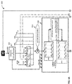
- FIG. 3 a functional block diagram of a video processing unit 300, analogous to the video processing unit 104 implemented by the broadcast network 100 of FIG. 1 or the video processing unit 204 implemented by the unicast network 200 of FIG. 2 , is illustrated in accordance with some embodiments of the present disclosure.
- the video processing unit 300 acquires a plurality of video transmission parameters for the video being transmitted, derives an optimum value for each of the plurality of video transmission parameters based on a predefined indicator of an acceptable quality of the video using meta-heuristic harmony search algorithm, and dynamically optimizes the quality of the video based on the optimum value for each of the plurality of video transmission parameters.
- the FR and video quality analyzer 301 receives raw video and extracts the FR of the raw video (i.e., initial video FR) along with indicator of quality of the raw video.
- FR and video quality analyzer 301 extracts MOS coefficients (i.e., a 1 , a 2 , a 3 , a 4 , and a 5 ) from the raw video.
- the FR comparator 302 takes initial FR as one of the inputs form FR and video quality analyzer 301 and takes optimized FR as the other input which is feedback from the optimized output.
- an acceptable range of MOS i.e., MOS Max , and MOS Min
- MOS Max MOS Max , and MOS Min
- the acceptable range of MOS may be predefined by the network operator, or the user receiving the video, or the user transmitting the video, or a third party enabling the video transmission.
- a range of PER i.e., PER Max and PER Min
- the range of PER may be initially provided by the network operator and is subsequently updated based on feedback from the network.
- a maximum iteration count may be provided to the video processing unit 300 for video quality optimization.
- SBR Max , SBR Min , FR Max , FR Min , PER Max , PER Min , MOS Max , MOS Min , and maximum iteration count proceeds through optimizer for optimization.
- the HM generator 304 generates a harmonic memory (HM) based on plurality of above discussed video transmission parameters.
- the HM is introduced as a [5 X HMS] matrix, where HMS denotes HM Size.
- the count of 5 comes with the 4 video transmission parameters (i.e., FR, SBR, PER, MOS) and a fitness function f(x) value.
- the improved HM identification module 308 passes the new solution through two decision block to check if the new solution is an improved one or not. If the new solution is smaller than the best solution, then the module 308 updates HM by replacing the best (i.e., the first) solution with the new one. In contrast, if the new solution is greater than the worst solution, then the module 308 discards the new solution and does not update HM. However, if the new solution lies between the best and worst solution then the module 308 finds the index i for which f i ⁇ 1 x ⁇ f new x ⁇ f i x and then updates HM by replacing the i th solution with the new one.
- the complete process of identifying new solution and improving the solution continues till the maximum iteration count and the best solution is produced as optimized FR, SBR, and MOS. It should be noted that as the number of iteration increases, optimum values of FR and SBR and minimum fitness value are derived. Alternatively, the process iterates till the completion of the video transmission.
- the video processing unit 300 may be implemented in programmable hardware devices such as programmable gate arrays, programmable array logic, programmable logic devices, and so forth. Alternatively, the video processing unit 300 may be implemented in software for execution by various types of processors.
- An identified engine of executable code may, for instance, comprise one or more physical or logical blocks of computer instructions which may, for instance, be organized as an object, procedure, function, module, or other construct. Nevertheless, the executables of an identified engine need not be physically located together, but may comprise disparate instructions stored in different locations which, when joined logically together, comprise the engine and achieve the stated purpose of the engine. Indeed, an engine of executable code could be a single instruction, or many instructions, and may even be distributed over several different code segments, among different applications, and across several memory devices.
- a variety of processes may be employed for dynamically optimizing a quality of a video being transmitted over a communication network.
- the exemplary system 100, 200 and the associated video processing unit 104, 204, 300 may dynamically optimize of the video being transmitted in real-time by the processes discussed herein.
- control logic and/or automated routines for performing the techniques and steps described herein may be implemented by the system 100, 200 and the associated video processing unit 104, 204, 300, either by hardware, software, or combinations of hardware and software.
- control logic 400 for dynamically optimizing a quality of a video being transmitted over a communication network via a system, such as system 100 or 200, is depicted via a flowchart in accordance with some embodiments of the present disclosure.
- the control logic 400 includes the steps of acquiring a plurality of video transmission parameters for the video being transmitted at step 401, and deriving an optimum value for each of the plurality of video transmission parameters based on a predefined indicator of an acceptable quality of the video using meta-heuristic harmony search algorithm at step 402.
- the control logic 400 further includes the step of dynamically optimizing the quality of the video based on the optimum value for each of the plurality of video transmission parameters at step 403.
- the plurality of video transmission parameters comprises at least one of a frame rate (FR), a sender bit rate (SBR), and a packet error rate (PER) for the video being transmitted.
- deriving the optimum value for each of the plurality of video transmission parameters at step 402 comprises determining a maximum frame rate, a maximum sender bit rate, and a minimum packet error rate for the predefined indicator of the acceptable quality of the video.
- the predefined indicator of the acceptable quality of the video comprises a predefined mean opinion score (MOS).
- deriving the optimum value for each of the plurality of video transmission parameters at step 402 comprises the steps of acquiring a plurality of MOS coefficients for the video, determining a MOS of the video based on the plurality of MOS coefficients and the plurality of video transmission parameters, determining a fitness function based on the MOS of the video and the predefined MOS, and deriving the optimum value for each of the plurality of video transmission parameters based on the fitness function.
- the control logic 300 includes the step of determining a minimum value, a maximum value, and a plurality of random values between the minimum value and the maximum value for each of the plurality of video transmission parameters and for the predefined MOS.
- control logic 300 includes the steps of adjusting the harmonic memory matrix by at least one of a harmony memory consideration rate (HMCR) and a pitch adjustment rate (PAR), identifying a new fitness function from the adjusted harmonic memory matrix, discarding the new fitness function or updating the harmonic memory matrix based on a comparison of the new fitness function with the minimum and the maximum fitness function, and iterating the adjusting, the identifying, the discarding or the updating steps at a predefined periodic interval for a predefined number of times or till the completion of the video transmission.
- dynamically optimizing the quality of the video at step 403 comprises the step of modifying the video based on at least one of an optimum frame rate and an optimum sender bit rate.
- control logic 500 for dynamically optimizing the quality of the video being transmitted over a communication network is depicted in greater detail via a flowchart in accordance with some embodiments of the present disclosure.
- the control logic 500 includes the step of receiving the raw video and extracting initial FR and MOS coefficients from the raw video via the FR and video quality analyzer at step 501.
- the control logic 500 further includes the step of receiving the initial FR extracted above and optimized FR as feedback from the output and comparing them to determine FR Max and FR Min via the FR comparator at step 502.
- the control logic 500 includes the step of finding an index i where the new solution fits in HM at step 514 and updating the HM by replacing the i th solution with the new one at step 515.
- the control logic 500 further includes the step of determining if the maximum iteration count has reached at step 516 and if so then stopping the process at step 517. If the maximum iteration count has not reached then the process of identifying new solution and improving the solution continues till the maximum iteration count.
- control logic 500 includes the step of finding the best solution from the sorted HM and determining optimized FR, SBR, and MOS from the best solution at step 518.
- the optimized FR and SBR are then provided as feedback input to the respective comparators at step 502 and 503.
- control logic 500 includes the step of modifying the raw video based on the optimized parameters via the video convertor at step 519 and producing the modified video as output for subsequent transmission.
- the above described techniques may take the form of computer or controller implemented processes and apparatuses for practicing those processes.
- the disclosure can also be embodied in the form of computer program code containing instructions embodied in tangible media, such as floppy diskettes, CD-ROMs, hard drives, or any other computer-readable storage medium, wherein, when the computer program code is loaded into and executed by a computer or controller, the computer becomes an apparatus for practicing the invention.
- the disclosure may also be embodied in the form of computer program code or signal, for example, whether stored in a storage medium, loaded into and/or executed by a computer or controller, or transmitted over some transmission medium, such as over electrical wiring or cabling, through fiber optics, or via electromagnetic radiation, wherein, when the computer program code is loaded into and executed by a computer, the computer becomes an apparatus for practicing the invention.
- the computer program code segments configure the microprocessor to create specific logic circuits.
Landscapes
- Engineering & Computer Science (AREA)
- Multimedia (AREA)
- Signal Processing (AREA)
- Databases & Information Systems (AREA)
- Computer Networks & Wireless Communication (AREA)
- Computer Security & Cryptography (AREA)
- Computing Systems (AREA)
- Health & Medical Sciences (AREA)
- Biomedical Technology (AREA)
- General Health & Medical Sciences (AREA)
- General Engineering & Computer Science (AREA)
- Two-Way Televisions, Distribution Of Moving Picture Or The Like (AREA)
Abstract
Description
- This disclosure relates generally to communication networks, and more particularly to a system and method for dynamically optimizing a quality of a video being transmitted over a communication network.
- Mobile digital devices such as wireless devices, including, for example, cellular telephones, smart phones, laptop computers, notebook computers, and tablet devices have become ubiquitous in recent years. With evolving lifestyles, improved technologies, and ever changing socio-economic behavior, people are increasingly using these digital devices, from where ever they are, to communicate with one another over voice and message, to consume a wide variety of digital contents, and to perform day-to-day activities. These functions have become an integral part of our daily lives. For example, in today's world, mobile devices are increasingly used for real-time image and video transmission in addition to basic voice transmission. People remain connected with their nearest and dearest ones through the video calling/video chatting facility. Additionally, it is employed for several other multimedia services such as for streaming of multimedia contents.
- In real-time video transmission, the quality of video plays a vital role. If quality degrades, it becomes very annoying in some scenarios like video chat, video conference, real-time streaming of a cricket match, and so forth. Technologists are continuously trying to find out new ways to increase speed and bandwidth of the mobile communication network to ensure uninterrupted and good quality streaming of multimedia contents such as video. The continuous evolution of mobile communication technologies for faster and better mobile broadband experiences resulted in 2G (speed up to 15 Kbps), 2.5G (speed up to 172 Kbps), 3G (speed up to 3.1 Mbps), 3.5G (speed up to 7.2 Mbps), and the latest LTE or 4G (up to 21 Mbps) communication technologies in rapid succession. However, it should be noted that spectrums or frequency band are an expensive recourse, which has to be utilized efficiently to support multiple services as well as multiple users. It is a great challenge to maximize the utilization of available bandwidth supporting multiple services, without sacrificing the quality of service. Further, even though the capacity and speed of the network are constantly increasing and its associated costs are declining, the amount of data travelling on the network is also still on the rise.
- In one embodiment, a method for optimizing dynamically optimizing a quality of a video being transmitted over a communication network is disclosed. In one example, the method comprises acquiring a plurality of video transmission parameters for the video being transmitted. The method further comprises deriving an optimum value for each of the plurality of video transmission parameters based on a predefined indicator of an acceptable quality of the video using meta-heuristic harmony search algorithm. The method further comprises dynamically optimizing the quality of the video based on the optimum value for each of the plurality of video transmission parameters.
- In one embodiment, a method for dynamically optimizing a quality of a video being transmitted over a communication network is disclosed. The method comprises: acquiring, via a processor, a plurality of video transmission parameters for the video being transmitted; deriving, via the processor, an optimum value for each of the plurality of video transmission parameters based on a predefined indicator of an acceptable quality of the video using meta-heuristic harmony search algorithm; and dynamically optimizing, via the processor, the quality of the video based on the optimum value for each of the plurality of video transmission parameters.
- In one embodiment, a system for dynamically optimizing a quality of a video being transmitted over a communication network is disclosed. In one example, the system comprises at least one processor and a memory communicatively coupled to the at least one processor. The memory stores processor-executable instructions, which, on execution, cause the processor to acquire a plurality of video transmission parameters for the video being transmitted. The processor-executable instructions, on execution, further cause the processor to derive an optimum value for each of the plurality of video transmission parameters based on a predefined indicator of an acceptable quality of the video using meta-heuristic harmony search algorithm. The processor-executable instructions, on execution, further cause the processor to dynamically optimize the quality of the video based on the optimum value for each of the plurality of video transmission parameters.
- In one embodiment, a non-transitory computer-readable medium storing computer-executable instructions for dynamically optimizing a quality of a video being transmitted over a communication network is disclosed. In one example, the stored instructions, when executed by a processor, cause the processor to acquire a plurality of video transmission parameters for the video being transmitted. The stored instructions, when executed by a processor, further cause the processor to derive an optimum value for each of the plurality of video transmission parameters based on a predefined indicator of an acceptable quality of the video using meta-heuristic harmony search algorithm. The stored instructions, when executed by a processor, further cause the processor to dynamically optimize the quality of the video based on the optimum value for each of the plurality of video transmission parameters.
- It is to be understood that both the foregoing general description and the following detailed description are exemplary and explanatory only and are not restrictive of the invention, as claimed.
- The accompanying drawings, which are incorporated in and constitute a part of this disclosure, illustrate exemplary embodiments and, together with the description, serve to explain the disclosed principles.
-
FIG. 1 is a block diagram of an exemplary broadcast system for dynamically optimizing a quality of a video being transmitted in accordance with some embodiments of the present disclosure; -
FIG. 2 is a block diagram of an exemplary unicast system for dynamically optimizing a quality of a video being transmitted in accordance with some embodiments of the present disclosure; -
FIG. 3 is a functional block diagram of a video processing unit in accordance with some embodiments of the present disclosure; -
FIG. 4 is a flow diagram of an exemplary process for dynamically optimizing a quality of a video being transmitted over a communication network in accordance with some embodiments of the present disclosure; -
FIGS. 5A and5B is a flow diagram of a detailed exemplary process for dynamically optimizing a quality of a video being transmitted in accordance with some embodiments of the present disclosure; and -
FIG. 6 is a block diagram of an exemplary computer system for implementing embodiments consistent with the present disclosure. - Exemplary embodiments are described with reference to the accompanying drawings. Wherever convenient, the same reference numbers are used throughout the drawings to refer to the same or like parts. While examples and features of disclosed principles are described herein, modifications, adaptations, and other implementations are possible without departing from the spirit and scope of the disclosed embodiments. It is intended that the following detailed description be considered as exemplary only, with the true scope and spirit being indicated by the following claims.
- There are mainly two ways of transmitting multimedia streams such as video streams over the network from the source to the destination: broadcast and unicast. Broadcast is a one-to-all communication between the source and the destinations. In contrast, Unicast is a one-to-one communication between two devices. Each of the two devices becomes the source while transmitting and the destination while receiving the multimedia streams. Referring now to
FIGS. 1 and2 , anexemplary broadcast system 100 and anexemplary unicast system 200 are illustrated in accordance with some embodiments of the present disclosure. In particular, thebroadcast system 100 and theunicast system 200 are adapted to dynamically optimize a quality of a video being transmitted in real-time. - In the
broadcast system 100, the multimedia streams are broadcasted from asource device 101 tomultiple destination devices 102 over acommunication device 103. In certain embodiments, thesource device 101 may be a camera enabled device such as a video camera, a digital camera, a smartphone, a laptop, or a tablet for acquiring and transmitting raw video or any other device for transmitting raw video. Similarly, thedestination device 102 may be a monitoring station or a recording server such as a personal computer, a laptop, a smartphone, or a tablet for receiving broadcasted video. In theunicast system 200, the multimedia streams are transmitted and received by each of thedevices communication device 203. Thedevices devices communication device - Additionally, in accordance with aspects of the present disclosure, the
broadcast system 100 comprises avideo processing unit 104 on the transmitter side for dynamically optimizing the quality of the video being transmitted in real-time. Thevideo processing unit 104 receives the raw video from thesource device 101, optimizes the video quality based on available bandwidth, and sends modified video to thecommunication device 103 for subsequent transmission through the network. Thebroadcast system 100 further comprises anetwork speed monitor 105 in each of the receiver module so as to constantly monitor the speed and provide the sender bit rate (SBR) feedback to thecommunication device 103. Thecommunication device 103 provides the received SBR feedback along with the packet error rate (PER) feedback to thevideo processing unit 104. Thevideo processing unit 104 uses the SBR and the PER feedback along with other inputs to modify the raw video. Further, in accordance with aspects of the present disclosure, theunicast system 200 comprises avideo processing unit 204 and a network speed monitor 205 on each side (i.e., receiver side as well as the transmitter side) as the modified video may be transmitted from both the end. - As will be described in greater detail in conjunction with
FIG. 3 , thevideo processing unit - For optimizing video quality, an indicator or a measure of video quality should be identified. A mean opinion score (MOS) and a peak signal to noise ratio (PSNR) are two well-known parameters typically employed to define or to measure the video quality. The techniques described in the present disclosure employs MOS as a measure or an indicator of video quality. However, as will be appreciated by those skilled in the art, the described techniques are equally workable if any other parameter (e.g., PSNR) is employed as a measure or an indicator of video quality.
- The MOS is employed by the described technique so as to ensure the quality of the video to be received at the receiver end before the transmission based on FR, SBR, and PER remains within an acceptable standard i.e., within an acceptable range of MOS. This acceptable range of MOS may be predefined by the network operator, or the user receiving the video, or the user transmitting the video, or a third party enabling the video transmission. The MOS range lies between 1 (low quality) to 5 (high quality) to rate the quality of a video. In some embodiments, the acceptable MOS range is between 3 and 5. Further, in some embodiments, the acceptable MOS range is between 3.5 and 4.5. MOS is determined by classifying the video into different video groups (e.g., slight movement, gentle walking, rapid movement, and so forth) based on spatial and temporal features of the video and is given as:

- The
video processing unit video processing unit video processing unit - Referring now to
FIG. 3 , a functional block diagram of avideo processing unit 300, analogous to thevideo processing unit 104 implemented by thebroadcast network 100 ofFIG. 1 or thevideo processing unit 204 implemented by theunicast network 200 ofFIG. 2 , is illustrated in accordance with some embodiments of the present disclosure. As will be described in greater detail below, thevideo processing unit 300 acquires a plurality of video transmission parameters for the video being transmitted, derives an optimum value for each of the plurality of video transmission parameters based on a predefined indicator of an acceptable quality of the video using meta-heuristic harmony search algorithm, and dynamically optimizes the quality of the video based on the optimum value for each of the plurality of video transmission parameters. The term "video transmission parameters" is preferably used herein to include requirements of the network for video transmission. The term "optimum value" is preferably used herein to refer to properties of the communications network allowing for the best possible quality of video transmission. Thevideo processing unit 300 includes various logical units to optimize the video quality. In some embodiments, thevideo processing unit 300 comprises a frame rate (FR) andvideo quality analyzer 301, a frame rate (FR)comparator 302, a sender bitrate (SBR)comparator 303, a harmonic memory (HM)generator 304, a harmonic memory (HM) sortingengine 305, a HMCR andPAR adjustment module 306, anew solution module 307, an improved harmonic memory (HM)identification module 308, and avideo converter 309. - The FR and
video quality analyzer 301 receives raw video and extracts the FR of the raw video (i.e., initial video FR) along with indicator of quality of the raw video. In some embodiments, where MOS is employed as the measure or the indicator of video quality, FR andvideo quality analyzer 301 extracts MOS coefficients (i.e., a1, a2, a3, a4, and a5) from the raw video. TheFR comparator 302 takes initial FR as one of the inputs form FR andvideo quality analyzer 301 and takes optimized FR as the other input which is feedback from the optimized output. The FR comparator 302 then compares both the inputs and directs the greater value in the FRMax probe and lesser one in the FRMin probe. As the system continues to run the difference between these two inputs iteratively decreases and as a result the difference of FRMax and FRMin (i.e. the range of FR in Harmonic Memory) also iteratively decreases. This leads to the selection of the best or optimized FR in a range of possible FRs. Similarly, theSBR comparator 303 takes initial SBR as one of the inputs from the network speed monitor and takes optimized SBR as the other input which is feedback from the optimized output. TheSBR comparator 303 then compares both the inputs and directs the greater value in the SBRMax probe and lesser one in the SBRMin probe. Again, as the system continues to run the difference between these two inputs iteratively decreases and as a result the difference of SBRMax and SBRMin (i.e. the range of SBR in Harmonic Memory) also decreases. This leads to the selection of the best or optimized SBR in a range of possible SBRs. - Additionally, an acceptable range of MOS (i.e., MOSMax, and MOSMin) is provided to the
video processing unit 300 for video quality optimization. As noted above, the acceptable range of MOS may be predefined by the network operator, or the user receiving the video, or the user transmitting the video, or a third party enabling the video transmission. Similarly, a range of PER (i.e., PERMax and PERMin) is provided to thevideo processing unit 300. The range of PER may be initially provided by the network operator and is subsequently updated based on feedback from the network. Further, a maximum iteration count may be provided to thevideo processing unit 300 for video quality optimization. Finally, SBRMax, SBRMin, FRMax, FRMin, PERMax, PERMin, MOSMax, MOSMin, and maximum iteration count proceeds through optimizer for optimization. - The
HM generator 304 generates a harmonic memory (HM) based on plurality of above discussed video transmission parameters. In some embodiments, the HM is introduced as a [5 X HMS] matrix, where HMS denotes HM Size. The count of 5 comes with the 4 video transmission parameters (i.e., FR, SBR, PER, MOS) and a fitness function f(x) value. The fitness function to be optimized is a function of the 4 video transmission parameters and is given as:
- In particular, the fitness function f(x) is given as:

- By minimizing this fitness function through harmony search algorithm, an optimum value for SBR and FR is determined so that user experiences the best video quality while at same time channel bandwidth is optimally utilized. As noted above, an increase in SBR and FR will increase the video quality i.e. MOS. However, it is desirable to determine best combination of SBR and FR so that the video quality is not compromised while at same time there is efficient utilization of channel bandwidth. Initially a random adjustment is made within the MAX and MIN values of these video transmission parameters using a uniform random number. These values then pass through a logical sub-unit, a fitness function calculator to get the f(x). Thus, the complete initial HM obtained.
- The initial HM then passes through a sorting process in the
HM sorting engine 305 that sorts the HM from best to worst value based on fitness function f(x) value. The best value implies smallest f(x) and worst value implies largest f(x). After the sorted HM is ready, it passes through a HMCR andPAR adjustment module 306 that adjusts the sorted HM by at least one of a harmony memory consideration rate (HMCR) and a pitch adjustment rate (PAR). The HMCR is the probability of choosing one value from the historic values stored in the HM, and (1-HMCR) is the probability of randomly choosing one feasible value not limited to those stored in the HM. For example, an HMCR of 0.95 indicates that the HS algorithm will choose the design variable value from historically stored values in the HM with a 95% probability and from the entire feasible range with a 5% probability. Further, every value in the HM is examined to determine whether it should be pitch-adjusted. The pitch adjusting process is performed only after a value is chosen from the HM. By way of example, a PAR of 0.3 indicates that the algorithm will choose a neighboring value with 30%*HMCR probability. A random solution is picked either with a probability of HMCR and the value slightly changed with PAR probability within or with a probability of (1-HMCR) outside of HM but within the value range of the parameters. Thenew solution module 307 finds the new solution based on the adjusted parameters from HMCR andPAR module 306. As will be appreciated, the new solution is the random solution that is picked for at least one of the HMCR and PAR adjustment. - The improved
HM identification module 308 passes the new solution through two decision block to check if the new solution is an improved one or not. If the new solution is smaller than the best solution, then themodule 308 updates HM by replacing the best (i.e., the first) solution with the new one. In contrast, if the new solution is greater than the worst solution, then themodule 308 discards the new solution and does not update HM. However, if the new solution lies between the best and worst solution then themodule 308 finds the index i for which
- As will be appreciated by those skilled in the art, the best or the first solution from the sorted or the updated HM is the one with optimized FR, SBR, and MOS. As noted above, the optimized FR and SBR are the feedback input to the
respective comparators video converter 309 takes raw video and optimized parameters as input, modifies the raw video based on the optimized parameters, and sends the modified video as output for subsequent transmission. In some embodiments, thevideo convertor 309 may be a frame rate convertor that modifies the raw video based on the optimized frame rate. - It should be noted that the
video processing unit 300 may be implemented in programmable hardware devices such as programmable gate arrays, programmable array logic, programmable logic devices, and so forth. Alternatively, thevideo processing unit 300 may be implemented in software for execution by various types of processors. An identified engine of executable code may, for instance, comprise one or more physical or logical blocks of computer instructions which may, for instance, be organized as an object, procedure, function, module, or other construct. Nevertheless, the executables of an identified engine need not be physically located together, but may comprise disparate instructions stored in different locations which, when joined logically together, comprise the engine and achieve the stated purpose of the engine. Indeed, an engine of executable code could be a single instruction, or many instructions, and may even be distributed over several different code segments, among different applications, and across several memory devices. - As will be appreciated by one skilled in the art, a variety of processes may be employed for dynamically optimizing a quality of a video being transmitted over a communication network. For example, the
exemplary system video processing unit system video processing unit video processing unit video processing unit - For example, referring now to
FIG. 4 ,exemplary control logic 400 for dynamically optimizing a quality of a video being transmitted over a communication network via a system, such assystem control logic 400 includes the steps of acquiring a plurality of video transmission parameters for the video being transmitted atstep 401, and deriving an optimum value for each of the plurality of video transmission parameters based on a predefined indicator of an acceptable quality of the video using meta-heuristic harmony search algorithm atstep 402. Thecontrol logic 400 further includes the step of dynamically optimizing the quality of the video based on the optimum value for each of the plurality of video transmission parameters atstep 403. - As noted above, in some embodiments, the plurality of video transmission parameters comprises at least one of a frame rate (FR), a sender bit rate (SBR), and a packet error rate (PER) for the video being transmitted. In some embodiments, deriving the optimum value for each of the plurality of video transmission parameters at
step 402 comprises determining a maximum frame rate, a maximum sender bit rate, and a minimum packet error rate for the predefined indicator of the acceptable quality of the video. - Additionally, as noted above, in some embodiments, the predefined indicator of the acceptable quality of the video comprises a predefined mean opinion score (MOS). In some embodiments, deriving the optimum value for each of the plurality of video transmission parameters at
step 402 comprises the steps of acquiring a plurality of MOS coefficients for the video, determining a MOS of the video based on the plurality of MOS coefficients and the plurality of video transmission parameters, determining a fitness function based on the MOS of the video and the predefined MOS, and deriving the optimum value for each of the plurality of video transmission parameters based on the fitness function. Further, in some embodiments, thecontrol logic 300 includes the step of determining a minimum value, a maximum value, and a plurality of random values between the minimum value and the maximum value for each of the plurality of video transmission parameters and for the predefined MOS. - In some embodiments, the
control logic 300 further includes the steps of generating a harmonic memory matrix, and sorting the harmonic memory matrix based on the fitness function. It should be noted that the harmonic memory matrix comprises the minimum, the plurality of random, and the maximum values for each of the plurality of video transmission parameters; the minimum, the plurality of random, and the maximum value for the predefined MOS; and a plurality of values for the fitness function determined based on the minimum, the plurality of random, and the maximum values for each of the plurality of video transmission parameters and for the predefined MOS. Additionally, it should be noted that the optimum value for each of the plurality of video transmission parameters corresponds to the fitness function having the minimum value. - Moreover, in some embodiments, the
control logic 300 includes the steps of adjusting the harmonic memory matrix by at least one of a harmony memory consideration rate (HMCR) and a pitch adjustment rate (PAR), identifying a new fitness function from the adjusted harmonic memory matrix, discarding the new fitness function or updating the harmonic memory matrix based on a comparison of the new fitness function with the minimum and the maximum fitness function, and iterating the adjusting, the identifying, the discarding or the updating steps at a predefined periodic interval for a predefined number of times or till the completion of the video transmission. Further, in some embodiments, dynamically optimizing the quality of the video atstep 403 comprises the step of modifying the video based on at least one of an optimum frame rate and an optimum sender bit rate. - Referring now to
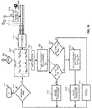
FIGS. 5A and5B ,exemplary control logic 500 for dynamically optimizing the quality of the video being transmitted over a communication network is depicted in greater detail via a flowchart in accordance with some embodiments of the present disclosure. As illustrated in the flowchart, thecontrol logic 500 includes the step of receiving the raw video and extracting initial FR and MOS coefficients from the raw video via the FR and video quality analyzer atstep 501. Thecontrol logic 500 further includes the step of receiving the initial FR extracted above and optimized FR as feedback from the output and comparing them to determine FRMax and FRMin via the FR comparator atstep 502. Similarly, thecontrol logic 500 include the step of receiving the initial SBR from the network speed monitor and optimized SBR as feedback from the output and comparing them to determine SBRMax and SBRMin via the SBR comparator atstep 503. Additionally, thecontrol logic 500 includes the step of receiving the MOSMax and MOSMin as well as PERMax and PERMin from the network operator. In some embodiments, thecontrol logic 500 include the step of receiving a maximum iteration count. Thecontrol logic 500 further includes the step of making a random adjustment within the MAX and MIN values of the video transmission parameters (e.g., FR, SBR, PER, and MOS) using a uniform random number atstep 504. - Additionally, the
control logic 500 includes the step of generating an initial HM matrix based on the plurality of video transmission parameters and MOS coefficients via the HM generator and the fitness function calculator atstep 505. Thecontrol logic 500 further includes the steps of sorting the initial HM based on fitness function f(x) value to generate a sorted HM via the HM sorting engine atstep 506, and adjusting the sortedHM 507 by at least one of a harmony memory consideration rate (HMCR) and a pitch adjustment rate (PAR) via the HMCR and PAR adjustment module atstep 508. Further, thecontrol logic 500 includes the step of finding the new solution based on the adjusted parameters atstep 509. Thecontrol logic 500 includes the step of checking if the new solution is an improved one or not via the improved HM identification module atstep step 510, then thecontrol logic 500 includes the step of updating HM by replacing the best (i.e., the first) solution with the new one atstep 512. In contrast, if the new solution is greater than the worst solution atstep 511, then thecontrol logic 500 includes the step of discarding the new solution and not updating HM atstep 513. However, if the new solution lies between the best and worst solution atstep control logic 500 includes the step of finding an index i where the new solution fits in HM atstep 514 and updating the HM by replacing the ith solution with the new one atstep 515. Thecontrol logic 500 further includes the step of determining if the maximum iteration count has reached atstep 516 and if so then stopping the process atstep 517. If the maximum iteration count has not reached then the process of identifying new solution and improving the solution continues till the maximum iteration count. - Moreover, the
control logic 500 includes the step of finding the best solution from the sorted HM and determining optimized FR, SBR, and MOS from the best solution atstep 518. The optimized FR and SBR are then provided as feedback input to the respective comparators atstep control logic 500 includes the step of modifying the raw video based on the optimized parameters via the video convertor atstep 519 and producing the modified video as output for subsequent transmission. - As will be also appreciated, the above described techniques may take the form of computer or controller implemented processes and apparatuses for practicing those processes. The disclosure can also be embodied in the form of computer program code containing instructions embodied in tangible media, such as floppy diskettes, CD-ROMs, hard drives, or any other computer-readable storage medium, wherein, when the computer program code is loaded into and executed by a computer or controller, the computer becomes an apparatus for practicing the invention. The disclosure may also be embodied in the form of computer program code or signal, for example, whether stored in a storage medium, loaded into and/or executed by a computer or controller, or transmitted over some transmission medium, such as over electrical wiring or cabling, through fiber optics, or via electromagnetic radiation, wherein, when the computer program code is loaded into and executed by a computer, the computer becomes an apparatus for practicing the invention. When implemented on a general-purpose microprocessor, the computer program code segments configure the microprocessor to create specific logic circuits.
- The disclosed methods and systems may be implemented on a conventional or a general-purpose computer system, such as a personal computer (PC) or server computer. Referring now to
FIG. 6 , a block diagram of anexemplary computer system 601 for implementing embodiments consistent with the present disclosure is illustrated. Variations ofcomputer system 601 may be used for implementingsystem video processing unit Computer system 601 may comprise a central processing unit ("CPU" or "processor") 602.Processor 602 may comprise at least one data processor for executing program components for executing user- or system-generated requests. A user may include a person, a person using a device such as such as those included in this disclosure, or such a device itself. The processor may include specialized processing units such as integrated system (bus) controllers, memory management control units, floating point units, graphics processing units, digital signal processing units, etc. The processor may include a microprocessor, such as AMD Athlon, Duron or Opteron, ARM's application, embedded or secure processors, IBM PowerPC, Intel's Core, Itanium, Xeon, Celeron or other line of processors, etc. Theprocessor 602 may be implemented using mainframe, distributed processor, multi-core, parallel, grid, or other architectures. Some embodiments may utilize embedded technologies like application-specific integrated circuits (ASICs), digital signal processors (DSPs), Field Programmable Gate Arrays (FPGAs), etc. -
Processor 602 may be disposed in communication with one or more input/output (I/O) devices via I/O interface 603. The I/O interface 603 may employ communication protocols/methods such as, without limitation, audio, analog, digital, monoaural, RCA, stereo, IEEE-1394, serial bus, universal serial bus (USB), infrared, PS/2, BNC, coaxial, component, composite, digital visual interface (DVI), high-definition multimedia interface (HDMI), RF antennas, S-Video, VGA, IEEE 802.n /b/g/n/x, Bluetooth, cellular (e.g., code-division multiple access (CDMA), high-speed packet access (HSPA+), global system for mobile communications (GSM), long-term evolution (LTE), WiMax, or the like), etc. - Using the I/
O interface 603, thecomputer system 601 may communicate with one or more I/O devices. For example, the input device 604 may be an antenna, keyboard, mouse, joystick, (infrared) remote control, camera, card reader, fax machine, dongle, biometric reader, microphone, touch screen, touchpad, trackball, sensor (e.g., accelerometer, light sensor, GPS, gyroscope, proximity sensor, or the like), stylus, scanner, storage device, transceiver, video device/source, visors, etc. Output device 605 may be a printer, fax machine, video display (e.g., cathode ray tube (CRT), liquid crystal display (LCD), light-emitting diode (LED), plasma, or the like), audio speaker, etc. In some embodiments, atransceiver 606 may be disposed in connection with theprocessor 602. The transceiver may facilitate various types of wireless transmission or reception. For example, the transceiver may include an antenna operatively connected to a transceiver chip (e.g., Texas Instruments WiLink WL1283, Broadcom BCM4750IUB8, Infineon Technologies X-Gold 618-PMB9800, or the like), providing IEEE 802.11a/b/g/n, Bluetooth, FM, global positioning system (GPS), 2G/3G HSDPA/HSUPA communications, etc. - In some embodiments, the
processor 602 may be disposed in communication with acommunication network 608 via anetwork interface 607. Thenetwork interface 607 may communicate with thecommunication network 608. The network interface may employ connection protocols including, without limitation, direct connect, Ethernet (e.g., twisted pair 10/100/1000 Base T), transmission control protocol/internet protocol (TCP/IP), token ring, IEEE 802.11a/b/g/n/x, etc. Thecommunication network 608 may include, without limitation, a direct interconnection, local area network (LAN), wide area network (WAN), wireless network (e.g., using Wireless Application Protocol), the Internet, etc. Using thenetwork interface 607 and thecommunication network 608, thecomputer system 601 may communicate withdevices computer system 601 may itself embody one or more of these devices. - In some embodiments, the
processor 602 may be disposed in communication with one or more memory devices (e.g.,RAM 613,ROM 614, etc.) via astorage interface 612. The storage interface may connect to memory devices including, without limitation, memory drives, removable disc drives, etc., employing connection protocols such as serial advanced technology attachment (SATA), integrated drive electronics (IDE), IEEE-1394, universal serial bus (USB), fiber channel, small computer systems interface (SCSI), etc. The memory drives may further include a drum, magnetic disc drive, magneto-optical drive, optical drive, redundant array of independent discs (RAID), solid-state memory devices, solid-state drives, etc. - The memory devices may store a collection of program or database components, including, without limitation, an operating system 616, user interface application 617, web browser 618, mail server 619, mail client 620, user/application data 621 (e.g., any data variables or data records discussed in this disclosure), etc. The operating system 616 may facilitate resource management and operation of the
computer system 601. Examples of operating systems include, without limitation, Apple Macintosh OS X, Unix, Unix-like system distributions (e.g., Berkeley Software Distribution (BSD), FreeBSD, NetBSD, OpenBSD, etc.), Linux distributions (e.g., Red Hat, Ubuntu, Kubuntu, etc.), IBM OS/2, Microsoft Windows (XP, Vista/7/8, etc.), Apple iOS, Google Android, Blackberry OS, or the like. User interface 617 may facilitate display, execution, interaction, manipulation, or operation of program components through textual or graphical facilities. For example, user interfaces may provide computer interaction interface elements on a display system operatively connected to thecomputer system 601, such as cursors, icons, check boxes, menus, scrollers, windows, widgets, etc. Graphical user interfaces (GUIs) may be employed, including, without limitation, Apple Macintosh operating systems' Aqua, IBM OS/2, Microsoft Windows (e.g., Aero, Metro, etc.), Unix X-Windows, web interface libraries (e.g., ActiveX, Java, Javascript, AJAX, HTML, Adobe Flash, etc.), or the like. - In some embodiments, the
computer system 601 may implement a web browser 618 stored program component. The web browser may be a hypertext viewing application, such as Microsoft Internet Explorer, Google Chrome, Mozilla Firefox, Apple Safari, etc. Secure web browsing may be provided using HTTPS (secure hypertext transport protocol), secure sockets layer (SSL), Transport Layer Security (TLS), etc. Web browsers may utilize facilities such as AJAX, DHTML, Adobe Flash, JavaScript, Java, application programming interfaces (APIs), etc. In some embodiments, thecomputer system 601 may implement a mail server 619 stored program component. The mail server may be an Internet mail server such as Microsoft Exchange, or the like. The mail server may utilize facilities such as ASP, ActiveX, ANSI C++/C#, Microsoft .NET, CGI scripts, Java, JavaScript, PERL, PHP, Python, WebObjects, etc. The mail server may utilize communication protocols such as internet message access protocol (IMAP), messaging application programming interface (MAPI), Microsoft Exchange, post office protocol (POP), simple mail transfer protocol (SMTP), or the like. In some embodiments, thecomputer system 601 may implement a mail client 620 stored program component. The mail client may be a mail viewing application, such as Apple Mail, Microsoft Entourage, Microsoft Outlook, Mozilla Thunderbird, etc. - In some embodiments,
computer system 601 may store user/application data 621, such as the data, variables, records, etc. (e.g., FR SBR, MOS, PER, MOS coefficients, HM, sorted HM, maximum iteration count, fitness function, optimized FR, optimized SBR, optimized MOS, and so forth) as described in this disclosure. Such databases may be implemented as fault-tolerant, relational, scalable, secure databases such as Oracle or Sybase. Alternatively, such databases may be implemented using standardized data structures, such as an array, hash, linked list, struct, structured text file (e.g., XML), table, or as object-oriented databases (e.g., using ObjectStore, Poet, Zope, etc.). Such databases may be consolidated or distributed, sometimes among the various computer systems discussed above in this disclosure. It is to be understood that the structure and operation of the any computer or database component may be combined, consolidated, or distributed in any working combination. - As will be appreciated by those skilled in the art, the techniques described in the various embodiments discussed above results in improvement in real-time video transmission quality and optimization of the channel bandwidth. In other words, the techniques provides for optimizing video quality for efficient utilization of channel bandwidth. The techniques employ a meta-heuristic harmony search algorithm to find the best choice of frame rate and transmission bit rate to optimize the MOS of real-time video transmission. For example, in some scenarios, the technique may provide that if a video is transmitted with 26 fps at a 1046 kbps, the user may be able to experience a good video quality (i.e., MOS > 4). This results in a significant saving of transmission bandwidth which may be utilized for providing other multimedia services. Thus, the techniques enable transmission of real-time video with the best possible quality in an optimized network bandwidth.
- Further, as will be appreciated by those skilled in the art, the techniques described in the various embodiments discussed above may be equally workable for other multimedia streams such as high definition audio, streaming text, streaming image, or a combination thereof. Similarly, MOS or any other suitable parameter may be employed as a measure or an indicator of quality of such multimedia streams.
- The specification has described system and method for dynamically optimizing quality of a video being transmitted in real-time. The illustrated steps are set out to explain the exemplary embodiments shown, and it should be anticipated that ongoing technological development will change the manner in which particular functions are performed. These examples are presented herein for purposes of illustration, and not limitation. Further, the boundaries of the functional building blocks have been arbitrarily defined herein for the convenience of the description. Alternative boundaries can be defined so long as the specified functions and relationships thereof are appropriately performed. Alternatives (including equivalents, extensions, variations, deviations, etc., of those described herein) will be apparent to persons skilled in the relevant art(s) based on the teachings contained herein. Such alternatives fall within the scope and spirit of the disclosed embodiments.
- Furthermore, one or more computer-readable storage media may be utilized in implementing embodiments consistent with the present disclosure. A computer-readable storage medium refers to any type of physical memory on which information or data readable by a processor may be stored. Thus, a computer-readable storage medium may store instructions for execution by one or more processors, including instructions for causing the processor(s) to perform steps or stages consistent with the embodiments described herein. The term "computer-readable medium" should be understood to include tangible items and exclude carrier waves and transient signals, i.e., be non-transitory. Examples include random access memory (RAM), read-only memory (ROM), volatile memory, nonvolatile memory, hard drives, CD ROMs, DVDs, flash drives, disks, and any other known physical storage media.
- It is intended that the disclosure and examples be considered as exemplary only, with a true scope and spirit of disclosed embodiments being indicated by the following claims.
Claims (11)
- A processor-implemented method for dynamically optimizing a quality of a video being transmitted over a communication network, the method comprising:acquiring a plurality of video transmission parameters for the video being transmitted;deriving an optimum value for each of the plurality of video transmission parameters based on a predefined indicator of an acceptable quality of the video using a meta-heuristic harmony search algorithm; anddynamically optimizing the quality of the video based on the optimum value for each of the plurality of video transmission parameters.
- The method of claim 1, wherein acquiring the plurality of video transmission parameters comprises acquiring at least one of a frame rate (FR), a sender bit rate (SBR), and a packet error rate (PER) for the video being transmitted.
- The method of claim 1 or claim 2, wherein deriving the optimum value for each of the plurality of video transmission parameters comprises determining a maximum frame rate, a maximum sender bit rate, and a minimum packet error rate for the predefined indicator of the acceptable quality of the video.
- The method of any preceding claim, wherein the predefined indicator of the acceptable quality of the video comprises a predefined mean opinion score (MOS).
- The method of claim 4, wherein deriving the optimum value for each of the plurality of video transmission parameters comprises:acquiring a plurality of MOS coefficients for the video;determining a MOS of the video based on the plurality of MOS coefficients and the plurality of video transmission parameters;determining a fitness function based on the MOS of the video and the predefined MOS; andderiving the optimum value for each of the plurality of video transmission parameters based on the fitness function.
- The method of claim 4 or claim 5, further comprising determining a minimum value, a maximum value, and a plurality of random values between the minimum value and the maximum value for each of the plurality of video transmission parameters and for the predefined MOS.
- The method of claim 6, further comprising:generating a harmonic memory matrix comprising:the minimum, the plurality of random, and the maximum values for each of the plurality of video transmission parameters,the minimum, the plurality of random, and the maximum value for the predefined MOS, anda plurality of values for the fitness function determined based on the minimum, the plurality of random, and the maximum values for each of the plurality of video transmission parameters and for the predefined MOS; andsorting the harmonic memory matrix based on the fitness function, wherein the optimum value for each of the plurality of video transmission parameters corresponds to the fitness function having the minimum value.
- The method of claim 7, further comprising:adjusting the harmonic memory matrix by at least one of a harmony memory consideration rate (HMCR) and a pitch adjustment rate (PAR);identifying a new fitness function from the adjusted harmonic memory matrix;discarding the new fitness function or updating the harmonic memory matrix based on a comparison of the new fitness function with the minimum and the maximum fitness function; anditerating the adjusting, the identifying, the discarding or the updating steps at a predefined periodic interval for a predefined number of times or till the completion of the video transmission.
- The method of any preceding claim, wherein dynamically optimizing the quality of the video comprises modifying the video based on at least one of an optimum frame rate and an optimum sender bit rate.
- A system for dynamically optimizing a quality of a video being transmitted over a communication network, comprising:at least one processor; anda computer-readable medium storing instructions that, when executed by the at least one processor, cause the at least one processor to perform the method of any preceding claim.
- A non-transitory computer-readable medium storing processor-executable instructions for performing the method of any one of claims 1 to 9.
Applications Claiming Priority (1)
| Application Number | Priority Date | Filing Date | Title |
|---|---|---|---|
| IN6390CH2015 | 2015-11-27 |
Publications (2)
| Publication Number | Publication Date |
|---|---|
| EP3174302A1 true EP3174302A1 (en) | 2017-05-31 |
| EP3174302B1 EP3174302B1 (en) | 2018-10-10 |
Family
ID=55359399
Family Applications (1)
| Application Number | Title | Priority Date | Filing Date |
|---|---|---|---|
| EP16154135.4A Active EP3174302B1 (en) | 2015-11-27 | 2016-02-03 | System and method for dynamically optimizing video quality during video transmission |
Country Status (3)
| Country | Link |
|---|---|
| US (1) | US9712888B2 (en) |
| EP (1) | EP3174302B1 (en) |
| CN (1) | CN106817582B (en) |
Cited By (1)
| Publication number | Priority date | Publication date | Assignee | Title |
|---|---|---|---|---|
| CN115119010A (en) * | 2022-06-29 | 2022-09-27 | 北京奇艺世纪科技有限公司 | Microphone connecting method and device, electronic equipment and storage medium |
Families Citing this family (3)
| Publication number | Priority date | Publication date | Assignee | Title |
|---|---|---|---|---|
| CN110364188A (en) * | 2019-07-12 | 2019-10-22 | 深圳创维-Rgb电子有限公司 | Audio playback method, device and computer-readable storage medium |
| CN113014969B (en) | 2019-12-19 | 2022-06-07 | 花瓣云科技有限公司 | Video playing control method, terminal device, server and storage medium |
| CN112822482B (en) * | 2020-12-31 | 2022-11-08 | 上海掌门科技有限公司 | Method and equipment for determining evaluation score of audio and video call |
Citations (1)
| Publication number | Priority date | Publication date | Assignee | Title |
|---|---|---|---|---|
| US20090225170A1 (en) * | 2006-05-09 | 2009-09-10 | Kazuhisa Yamagishi | Video Quality Estimation Apparatus, Method, and Program |
Family Cites Families (6)
| Publication number | Priority date | Publication date | Assignee | Title |
|---|---|---|---|---|
| US8018850B2 (en) * | 2004-02-23 | 2011-09-13 | Sharp Laboratories Of America, Inc. | Wireless video transmission system |
| US7784076B2 (en) * | 2004-10-30 | 2010-08-24 | Sharp Laboratories Of America, Inc. | Sender-side bandwidth estimation for video transmission with receiver packet buffer |
| US7797723B2 (en) * | 2004-10-30 | 2010-09-14 | Sharp Laboratories Of America, Inc. | Packet scheduling for video transmission with sender queue control |
| US8356327B2 (en) * | 2004-10-30 | 2013-01-15 | Sharp Laboratories Of America, Inc. | Wireless video transmission system |
| US9544602B2 (en) * | 2005-12-30 | 2017-01-10 | Sharp Laboratories Of America, Inc. | Wireless video transmission system |
| US8180906B2 (en) * | 2009-03-11 | 2012-05-15 | International Business Machines Corporation | Dynamically optimizing delivery of multimedia content over a network |
-
2016
- 2016-01-12 US US14/993,825 patent/US9712888B2/en active Active
- 2016-02-03 EP EP16154135.4A patent/EP3174302B1/en active Active
- 2016-03-29 CN CN201610186078.6A patent/CN106817582B/en active Active
Patent Citations (1)
| Publication number | Priority date | Publication date | Assignee | Title |
|---|---|---|---|---|
| US20090225170A1 (en) * | 2006-05-09 | 2009-09-10 | Kazuhisa Yamagishi | Video Quality Estimation Apparatus, Method, and Program |
Non-Patent Citations (3)
| Title |
|---|
| ANONYMOUS: "Harmony search - Wikipedia, the free encyclopedia", 24 September 2015 (2015-09-24), XP055263431, Retrieved from the Internet <URL:https://en.wikipedia.org/w/index.php?title=Harmony_search&oldid=682533435> [retrieved on 20160406] * |
| MAHDAVI ET AL: "An improved harmony search algorithm for solving optimization problems", APPLIED MATHEMATICS AND COMPUTATION, ELSEVIER, US, vol. 188, no. 2, 11 May 2007 (2007-05-11), pages 1567 - 1579, XP022070721, ISSN: 0096-3003, DOI: 10.1016/J.AMC.2006.11.033 * |
| SAMIR MEDJIAH ET AL: "Scalable video streaming over P2P networks: A matter of harmony?", COMPUTER AIDED MODELING AND DESIGN OF COMMUNICATION LINKS AND NETWORKS (CAMAD), 2011 IEEE 16TH INTERNATIONAL WORKSHOP ON, IEEE, 10 June 2011 (2011-06-10), pages 127 - 132, XP031957248, ISBN: 978-1-61284-281-3, DOI: 10.1109/CAMAD.2011.5941101 * |
Cited By (2)
| Publication number | Priority date | Publication date | Assignee | Title |
|---|---|---|---|---|
| CN115119010A (en) * | 2022-06-29 | 2022-09-27 | 北京奇艺世纪科技有限公司 | Microphone connecting method and device, electronic equipment and storage medium |
| CN115119010B (en) * | 2022-06-29 | 2023-07-25 | 北京奇艺世纪科技有限公司 | Wheat connecting method, device, electronic equipment and storage medium |
Also Published As
| Publication number | Publication date |
|---|---|
| CN106817582A (en) | 2017-06-09 |
| EP3174302B1 (en) | 2018-10-10 |
| CN106817582B (en) | 2019-03-12 |
| US9712888B2 (en) | 2017-07-18 |
| US20170155969A1 (en) | 2017-06-01 |
Similar Documents
| Publication | Publication Date | Title |
|---|---|---|
| US10771807B1 (en) | System and method for compressing video using deep learning | |
| EP3790356B1 (en) | System and method of maintenance of network slice templates for slice orchestration | |
| US10182098B2 (en) | Method and system for proactively selecting a content distribution network (CDN) for delivering content | |
| US10701593B2 (en) | Method and systems for performing orchestration of services in a next generation mobile core network | |
| US10257867B2 (en) | Systems and methods for effective physical cell identifier reuse | |
| US10491758B2 (en) | Method and system for optimizing image data for data transmission | |
| EP3462684A1 (en) | Method and system for adaptive and context-aware service function chaining in communication networks | |
| EP3217753B1 (en) | Methods and systems for adaptive scheduling of packets in a wireless broadband network | |
| US11308331B2 (en) | Multimedia content summarization method and system thereof | |
| EP3174302B1 (en) | System and method for dynamically optimizing video quality during video transmission | |
| US10686783B2 (en) | Method and system for establishing a secure access connection with electronic devices | |
| EP3293928A1 (en) | System and method for transmitting data over a communication network | |
| CN105657731A (en) | System and method for traffic offloading for optimal network performance in a wireless heterogeneous broadband network | |
| US10536380B2 (en) | Method and system for intelligent link load balancing | |
| US20160234734A1 (en) | Method and system for automatically creating a neighbor list | |
| US20180219924A1 (en) | Method and System for Providing Interactive Control of Shared Content Over a Video Conference | |
| US20160183284A1 (en) | System and method for adaptive downlink scheduler for wireless networks | |
| US10917375B2 (en) | Method and device for managing messages in a communication device | |
| US9307459B2 (en) | Method and system for neighbor reporting in a mobile communication network | |
| US20190297371A1 (en) | Method and a system for network based multimedia content recording in a cloud | |
| US20170373965A1 (en) | Methods and systems for detecting and transferring defect information during manufacturing processes | |
| EP3035759A1 (en) | System and method for adaptive downlink scheduling for wireless networks | |
| US9917999B2 (en) | System and method for capturing multi-media of an area of interest using multi-media capturing devices | |
| CN106804032B (en) | Admission control method and system for D2D communication in wireless broadband network | |
| EP3021610A1 (en) | Systems and methods for effective physical cell identifier reuse |
Legal Events
| Date | Code | Title | Description |
|---|---|---|---|
| PUAI | Public reference made under article 153(3) epc to a published international application that has entered the european phase |
Free format text: ORIGINAL CODE: 0009012 |
|
| STAA | Information on the status of an ep patent application or granted ep patent |
Free format text: STATUS: THE APPLICATION HAS BEEN PUBLISHED |
|
| AK | Designated contracting states |
Kind code of ref document: A1 Designated state(s): AL AT BE BG CH CY CZ DE DK EE ES FI FR GB GR HR HU IE IS IT LI LT LU LV MC MK MT NL NO PL PT RO RS SE SI SK SM TR |
|
| AX | Request for extension of the european patent |
Extension state: BA ME |
|
| STAA | Information on the status of an ep patent application or granted ep patent |
Free format text: STATUS: REQUEST FOR EXAMINATION WAS MADE |
|
| 17P | Request for examination filed |
Effective date: 20171130 |
|
| RBV | Designated contracting states (corrected) |
Designated state(s): AL AT BE BG CH CY CZ DE DK EE ES FI FR GB GR HR HU IE IS IT LI LT LU LV MC MK MT NL NO PL PT RO RS SE SI SK SM TR |
|
| GRAP | Despatch of communication of intention to grant a patent |
Free format text: ORIGINAL CODE: EPIDOSNIGR1 |
|
| STAA | Information on the status of an ep patent application or granted ep patent |
Free format text: STATUS: GRANT OF PATENT IS INTENDED |
|
| INTG | Intention to grant announced |
Effective date: 20180502 |
|
| GRAS | Grant fee paid |
Free format text: ORIGINAL CODE: EPIDOSNIGR3 |
|
| GRAA | (expected) grant |
Free format text: ORIGINAL CODE: 0009210 |
|
| STAA | Information on the status of an ep patent application or granted ep patent |
Free format text: STATUS: THE PATENT HAS BEEN GRANTED |
|
| AK | Designated contracting states |
Kind code of ref document: B1 Designated state(s): AL AT BE BG CH CY CZ DE DK EE ES FI FR GB GR HR HU IE IS IT LI LT LU LV MC MK MT NL NO PL PT RO RS SE SI SK SM TR |
|
| REG | Reference to a national code |
Ref country code: GB Ref legal event code: FG4D |
|
| REG | Reference to a national code |
Ref country code: CH Ref legal event code: EP Ref country code: AT Ref legal event code: REF Ref document number: 1052663 Country of ref document: AT Kind code of ref document: T Effective date: 20181015 |
|
| REG | Reference to a national code |
Ref country code: IE Ref legal event code: FG4D |
|
| REG | Reference to a national code |
Ref country code: DE Ref legal event code: R096 Ref document number: 602016006287 Country of ref document: DE |
|
| REG | Reference to a national code |
Ref country code: NL Ref legal event code: MP Effective date: 20181010 |
|
| REG | Reference to a national code |
Ref country code: LT Ref legal event code: MG4D |
|
| REG | Reference to a national code |
Ref country code: AT Ref legal event code: MK05 Ref document number: 1052663 Country of ref document: AT Kind code of ref document: T Effective date: 20181010 |
|
| PG25 | Lapsed in a contracting state [announced via postgrant information from national office to epo] |
Ref country code: NL Free format text: LAPSE BECAUSE OF FAILURE TO SUBMIT A TRANSLATION OF THE DESCRIPTION OR TO PAY THE FEE WITHIN THE PRESCRIBED TIME-LIMIT Effective date: 20181010 |
|
| PG25 | Lapsed in a contracting state [announced via postgrant information from national office to epo] |
Ref country code: ES Free format text: LAPSE BECAUSE OF FAILURE TO SUBMIT A TRANSLATION OF THE DESCRIPTION OR TO PAY THE FEE WITHIN THE PRESCRIBED TIME-LIMIT Effective date: 20181010 Ref country code: BG Free format text: LAPSE BECAUSE OF FAILURE TO SUBMIT A TRANSLATION OF THE DESCRIPTION OR TO PAY THE FEE WITHIN THE PRESCRIBED TIME-LIMIT Effective date: 20190110 Ref country code: LT Free format text: LAPSE BECAUSE OF FAILURE TO SUBMIT A TRANSLATION OF THE DESCRIPTION OR TO PAY THE FEE WITHIN THE PRESCRIBED TIME-LIMIT Effective date: 20181010 Ref country code: PL Free format text: LAPSE BECAUSE OF FAILURE TO SUBMIT A TRANSLATION OF THE DESCRIPTION OR TO PAY THE FEE WITHIN THE PRESCRIBED TIME-LIMIT Effective date: 20181010 Ref country code: HR Free format text: LAPSE BECAUSE OF FAILURE TO SUBMIT A TRANSLATION OF THE DESCRIPTION OR TO PAY THE FEE WITHIN THE PRESCRIBED TIME-LIMIT Effective date: 20181010 Ref country code: IS Free format text: LAPSE BECAUSE OF FAILURE TO SUBMIT A TRANSLATION OF THE DESCRIPTION OR TO PAY THE FEE WITHIN THE PRESCRIBED TIME-LIMIT Effective date: 20190210 Ref country code: NO Free format text: LAPSE BECAUSE OF FAILURE TO SUBMIT A TRANSLATION OF THE DESCRIPTION OR TO PAY THE FEE WITHIN THE PRESCRIBED TIME-LIMIT Effective date: 20190110 Ref country code: LV Free format text: LAPSE BECAUSE OF FAILURE TO SUBMIT A TRANSLATION OF THE DESCRIPTION OR TO PAY THE FEE WITHIN THE PRESCRIBED TIME-LIMIT Effective date: 20181010 Ref country code: AT Free format text: LAPSE BECAUSE OF FAILURE TO SUBMIT A TRANSLATION OF THE DESCRIPTION OR TO PAY THE FEE WITHIN THE PRESCRIBED TIME-LIMIT Effective date: 20181010 Ref country code: FI Free format text: LAPSE BECAUSE OF FAILURE TO SUBMIT A TRANSLATION OF THE DESCRIPTION OR TO PAY THE FEE WITHIN THE PRESCRIBED TIME-LIMIT Effective date: 20181010 |
|
| PG25 | Lapsed in a contracting state [announced via postgrant information from national office to epo] |
Ref country code: SE Free format text: LAPSE BECAUSE OF FAILURE TO SUBMIT A TRANSLATION OF THE DESCRIPTION OR TO PAY THE FEE WITHIN THE PRESCRIBED TIME-LIMIT Effective date: 20181010 Ref country code: GR Free format text: LAPSE BECAUSE OF FAILURE TO SUBMIT A TRANSLATION OF THE DESCRIPTION OR TO PAY THE FEE WITHIN THE PRESCRIBED TIME-LIMIT Effective date: 20190111 Ref country code: AL Free format text: LAPSE BECAUSE OF FAILURE TO SUBMIT A TRANSLATION OF THE DESCRIPTION OR TO PAY THE FEE WITHIN THE PRESCRIBED TIME-LIMIT Effective date: 20181010 Ref country code: RS Free format text: LAPSE BECAUSE OF FAILURE TO SUBMIT A TRANSLATION OF THE DESCRIPTION OR TO PAY THE FEE WITHIN THE PRESCRIBED TIME-LIMIT Effective date: 20181010 Ref country code: PT Free format text: LAPSE BECAUSE OF FAILURE TO SUBMIT A TRANSLATION OF THE DESCRIPTION OR TO PAY THE FEE WITHIN THE PRESCRIBED TIME-LIMIT Effective date: 20190210 |
|
| REG | Reference to a national code |
Ref country code: DE Ref legal event code: R097 Ref document number: 602016006287 Country of ref document: DE |
|
| PG25 | Lapsed in a contracting state [announced via postgrant information from national office to epo] |
Ref country code: IT Free format text: LAPSE BECAUSE OF FAILURE TO SUBMIT A TRANSLATION OF THE DESCRIPTION OR TO PAY THE FEE WITHIN THE PRESCRIBED TIME-LIMIT Effective date: 20181010 Ref country code: DK Free format text: LAPSE BECAUSE OF FAILURE TO SUBMIT A TRANSLATION OF THE DESCRIPTION OR TO PAY THE FEE WITHIN THE PRESCRIBED TIME-LIMIT Effective date: 20181010 Ref country code: CZ Free format text: LAPSE BECAUSE OF FAILURE TO SUBMIT A TRANSLATION OF THE DESCRIPTION OR TO PAY THE FEE WITHIN THE PRESCRIBED TIME-LIMIT Effective date: 20181010 |
|
| PLBE | No opposition filed within time limit |
Free format text: ORIGINAL CODE: 0009261 |
|
| STAA | Information on the status of an ep patent application or granted ep patent |
Free format text: STATUS: NO OPPOSITION FILED WITHIN TIME LIMIT |
|
| PG25 | Lapsed in a contracting state [announced via postgrant information from national office to epo] |
Ref country code: SK Free format text: LAPSE BECAUSE OF FAILURE TO SUBMIT A TRANSLATION OF THE DESCRIPTION OR TO PAY THE FEE WITHIN THE PRESCRIBED TIME-LIMIT Effective date: 20181010 Ref country code: RO Free format text: LAPSE BECAUSE OF FAILURE TO SUBMIT A TRANSLATION OF THE DESCRIPTION OR TO PAY THE FEE WITHIN THE PRESCRIBED TIME-LIMIT Effective date: 20181010 Ref country code: SM Free format text: LAPSE BECAUSE OF FAILURE TO SUBMIT A TRANSLATION OF THE DESCRIPTION OR TO PAY THE FEE WITHIN THE PRESCRIBED TIME-LIMIT Effective date: 20181010 Ref country code: EE Free format text: LAPSE BECAUSE OF FAILURE TO SUBMIT A TRANSLATION OF THE DESCRIPTION OR TO PAY THE FEE WITHIN THE PRESCRIBED TIME-LIMIT Effective date: 20181010 |
|
| 26N | No opposition filed |
Effective date: 20190711 |
|
| REG | Reference to a national code |
Ref country code: CH Ref legal event code: PL |
|
| PG25 | Lapsed in a contracting state [announced via postgrant information from national office to epo] |
Ref country code: SI Free format text: LAPSE BECAUSE OF FAILURE TO SUBMIT A TRANSLATION OF THE DESCRIPTION OR TO PAY THE FEE WITHIN THE PRESCRIBED TIME-LIMIT Effective date: 20181010 Ref country code: MC Free format text: LAPSE BECAUSE OF FAILURE TO SUBMIT A TRANSLATION OF THE DESCRIPTION OR TO PAY THE FEE WITHIN THE PRESCRIBED TIME-LIMIT Effective date: 20181010 Ref country code: LU Free format text: LAPSE BECAUSE OF NON-PAYMENT OF DUE FEES Effective date: 20190203 |
|
| REG | Reference to a national code |
Ref country code: BE Ref legal event code: MM Effective date: 20190228 |
|
| REG | Reference to a national code |
Ref country code: IE Ref legal event code: MM4A |
|
| PG25 | Lapsed in a contracting state [announced via postgrant information from national office to epo] |
Ref country code: CH Free format text: LAPSE BECAUSE OF NON-PAYMENT OF DUE FEES Effective date: 20190228 Ref country code: LI Free format text: LAPSE BECAUSE OF NON-PAYMENT OF DUE FEES Effective date: 20190228 |
|
| PG25 | Lapsed in a contracting state [announced via postgrant information from national office to epo] |
Ref country code: IE Free format text: LAPSE BECAUSE OF NON-PAYMENT OF DUE FEES Effective date: 20190203 |
|
| PG25 | Lapsed in a contracting state [announced via postgrant information from national office to epo] |
Ref country code: BE Free format text: LAPSE BECAUSE OF NON-PAYMENT OF DUE FEES Effective date: 20190228 |
|
| PG25 | Lapsed in a contracting state [announced via postgrant information from national office to epo] |
Ref country code: TR Free format text: LAPSE BECAUSE OF FAILURE TO SUBMIT A TRANSLATION OF THE DESCRIPTION OR TO PAY THE FEE WITHIN THE PRESCRIBED TIME-LIMIT Effective date: 20181010 |
|
| PG25 | Lapsed in a contracting state [announced via postgrant information from national office to epo] |
Ref country code: MT Free format text: LAPSE BECAUSE OF NON-PAYMENT OF DUE FEES Effective date: 20190203 |
|
| PG25 | Lapsed in a contracting state [announced via postgrant information from national office to epo] |
Ref country code: CY Free format text: LAPSE BECAUSE OF FAILURE TO SUBMIT A TRANSLATION OF THE DESCRIPTION OR TO PAY THE FEE WITHIN THE PRESCRIBED TIME-LIMIT Effective date: 20181010 |
|
| PG25 | Lapsed in a contracting state [announced via postgrant information from national office to epo] |
Ref country code: HU Free format text: LAPSE BECAUSE OF FAILURE TO SUBMIT A TRANSLATION OF THE DESCRIPTION OR TO PAY THE FEE WITHIN THE PRESCRIBED TIME-LIMIT; INVALID AB INITIO Effective date: 20160203 |
|
| PG25 | Lapsed in a contracting state [announced via postgrant information from national office to epo] |
Ref country code: MK Free format text: LAPSE BECAUSE OF FAILURE TO SUBMIT A TRANSLATION OF THE DESCRIPTION OR TO PAY THE FEE WITHIN THE PRESCRIBED TIME-LIMIT Effective date: 20181010 |
|
| P01 | Opt-out of the competence of the unified patent court (upc) registered |
Effective date: 20230605 |
|
| PGFP | Annual fee paid to national office [announced via postgrant information from national office to epo] |
Ref country code: GB Payment date: 20260112 Year of fee payment: 11 |
|
| PGFP | Annual fee paid to national office [announced via postgrant information from national office to epo] |
Ref country code: DE Payment date: 20260107 Year of fee payment: 11 |
|
| PGFP | Annual fee paid to national office [announced via postgrant information from national office to epo] |
Ref country code: FR Payment date: 20260108 Year of fee payment: 11 |