EP3174278A1 - Image reading apparatus - Google Patents
Image reading apparatus Download PDFInfo
- Publication number
- EP3174278A1 EP3174278A1 EP16200881.7A EP16200881A EP3174278A1 EP 3174278 A1 EP3174278 A1 EP 3174278A1 EP 16200881 A EP16200881 A EP 16200881A EP 3174278 A1 EP3174278 A1 EP 3174278A1
- Authority
- EP
- European Patent Office
- Prior art keywords
- light amount
- light
- luminance
- line period
- light emitting
- Prior art date
- Legal status (The legal status is an assumption and is not a legal conclusion. Google has not performed a legal analysis and makes no representation as to the accuracy of the status listed.)
- Granted
Links
Images



Classifications
-
- H—ELECTRICITY
- H04—ELECTRIC COMMUNICATION TECHNIQUE
- H04N—PICTORIAL COMMUNICATION, e.g. TELEVISION
- H04N1/00—Scanning, transmission or reproduction of documents or the like, e.g. facsimile transmission; Details thereof
- H04N1/024—Details of scanning heads ; Means for illuminating the original
- H04N1/028—Details of scanning heads ; Means for illuminating the original for picture information pick-up
- H04N1/02815—Means for illuminating the original, not specific to a particular type of pick-up head
- H04N1/02885—Means for compensating spatially uneven illumination, e.g. an aperture arrangement
-
- H—ELECTRICITY
- H04—ELECTRIC COMMUNICATION TECHNIQUE
- H04N—PICTORIAL COMMUNICATION, e.g. TELEVISION
- H04N1/00—Scanning, transmission or reproduction of documents or the like, e.g. facsimile transmission; Details thereof
- H04N1/00002—Diagnosis, testing or measuring; Detecting, analysing or monitoring not otherwise provided for
- H04N1/00007—Diagnosis, testing or measuring; Detecting, analysing or monitoring not otherwise provided for relating to particular apparatus or devices
- H04N1/00013—Reading apparatus
-
- H—ELECTRICITY
- H04—ELECTRIC COMMUNICATION TECHNIQUE
- H04N—PICTORIAL COMMUNICATION, e.g. TELEVISION
- H04N1/00—Scanning, transmission or reproduction of documents or the like, e.g. facsimile transmission; Details thereof
- H04N1/00002—Diagnosis, testing or measuring; Detecting, analysing or monitoring not otherwise provided for
- H04N1/00026—Methods therefor
- H04N1/00068—Calculating or estimating
-
- H—ELECTRICITY
- H04—ELECTRIC COMMUNICATION TECHNIQUE
- H04N—PICTORIAL COMMUNICATION, e.g. TELEVISION
- H04N1/00—Scanning, transmission or reproduction of documents or the like, e.g. facsimile transmission; Details thereof
- H04N1/00002—Diagnosis, testing or measuring; Detecting, analysing or monitoring not otherwise provided for
- H04N1/00071—Diagnosis, testing or measuring; Detecting, analysing or monitoring not otherwise provided for characterised by the action taken
- H04N1/00082—Adjusting or controlling
-
- H—ELECTRICITY
- H04—ELECTRIC COMMUNICATION TECHNIQUE
- H04N—PICTORIAL COMMUNICATION, e.g. TELEVISION
- H04N1/00—Scanning, transmission or reproduction of documents or the like, e.g. facsimile transmission; Details thereof
- H04N1/40—Picture signal circuits
- H04N1/40056—Circuits for driving or energising particular reading heads or original illumination means
-
- H—ELECTRICITY
- H04—ELECTRIC COMMUNICATION TECHNIQUE
- H04N—PICTORIAL COMMUNICATION, e.g. TELEVISION
- H04N1/00—Scanning, transmission or reproduction of documents or the like, e.g. facsimile transmission; Details thereof
- H04N1/04—Scanning arrangements, i.e. arrangements for the displacement of active reading or reproducing elements relative to the original or reproducing medium, or vice versa
- H04N1/10—Scanning arrangements, i.e. arrangements for the displacement of active reading or reproducing elements relative to the original or reproducing medium, or vice versa using flat picture-bearing surfaces
- H04N1/1013—Scanning arrangements, i.e. arrangements for the displacement of active reading or reproducing elements relative to the original or reproducing medium, or vice versa using flat picture-bearing surfaces with sub-scanning by translatory movement of at least a part of the main-scanning components
-
- H—ELECTRICITY
- H04—ELECTRIC COMMUNICATION TECHNIQUE
- H04N—PICTORIAL COMMUNICATION, e.g. TELEVISION
- H04N1/00—Scanning, transmission or reproduction of documents or the like, e.g. facsimile transmission; Details thereof
- H04N1/40—Picture signal circuits
- H04N1/407—Control or modification of tonal gradation or of extreme levels, e.g. background level
- H04N1/4076—Control or modification of tonal gradation or of extreme levels, e.g. background level dependent on references outside the picture
-
- H—ELECTRICITY
- H04—ELECTRIC COMMUNICATION TECHNIQUE
- H04N—PICTORIAL COMMUNICATION, e.g. TELEVISION
- H04N2201/00—Indexing scheme relating to scanning, transmission or reproduction of documents or the like, and to details thereof
- H04N2201/0077—Types of the still picture apparatus
- H04N2201/0081—Image reader
Definitions
- the present invention relates to an image reading apparatus that quickly determines an appropriate light amount for each line period.
- Image reading apparatuses include a light emitting element that emits a light, a light receiving element that receives the reflected light, and a reference density board. For example, when a power supply of an image reading apparatus is switched on, the light emitting element emits a light on the reference density board, and the light receiving element receives the light reflected by the reference density board. The image reading apparatus adjusts, based on the received light amount, the light amount emitted by the light emitting element.
- the line period refers to a reading interval set for reading an original document line by line.
- the line period is long, an image can be appropriately read even with a small light amount.
- the line period is short, it is necessary to increase the light amount to appropriately read an image.
- an appropriate light amount must be set for each image reading setting, in other words, for each line period.
- Patent Document 1 Japanese Patent Application Laid-open No. 2013-73286 discloses a paper sheet recognition apparatus that detects a transporting speed of a banknote BL to be read, and according to the transporting speed of the banknote BL, corrects the light amount emitted by a light emitting element.
- one approach is to, for each line period, emit a light from the light emitting element at a given light emitting amount, receive the reflected light with the light receiving element, calculate a luminance based on the received light amount, and determine the light emitting amount of the light emitting element so that the calculated luminance is within a predetermined range.
- the light emitting amount is changed to determine an appropriate light emitting amount so that the luminance is within the predetermined range.
- the present invention has been made in view of such circumstances, and it is an object of the present invention to provide an image reading apparatus that quickly determines an appropriate light amount for each line period.
- an image reading apparatus including a light emitting element that emits a light; a light receiving element that receives the light reflected by a reference board upon being emitted from the light emitting element; a line period setter that sequentially sets a line period from among a plurality of line periods having mutually different intervals of a light receiving start signal sent from the light receiving element; a luminance calculator that calculates a luminance based on a light amount received by the light receiving element in the line period set by the line period setter; a storage that stores therein a plurality of reference light amounts each of which is a reference light amount of the light emitted by the light emitting element; and a light amount setter that, in each line period, causes the light emitting element to emit the light with gradually changing the reference light amount from a reference light amount set as a default value among the plurality of reference light amounts stored in the storage, identifies a reference light amount so that the luminance
- the light amount setter causes the light emitting element to emit the light with gradually changing the reference light amount from the reference light amount that is set as the default value among the plurality of reference light amounts that is stored in the storage, identifies a reference light amount so that the luminance calculated by the luminance calculator is within the predetermined range, sets the identified reference light amount as the default value in the next line period, and causes the storage to store the identified reference light amount. Therefore, upon setting the light amount of the light emitting element in a given line period, the luminance can be calculated by considering the set light amount as the reference light amount in the other line periods, and it can be determined whether the calculated luminance is within the predetermined range. Thus, compared to the conventional technology, a part of the process can be omitted, and the appropriate light amount in each line period can be determined quickly.
- FIG. 1 is a structural diagram of the image reading apparatus according to an embodiment of the present invention.
- an image reading apparatus 1 includes a platen 200, a reading unit 100, and a controlling unit 10.
- a white reference density board 201 to be used for adjusting the light amount, and a colorless transparent document reading glass 202 to be used for reading an original document are arranged on the platen 200.
- the reading unit 100 is arranged below the platen 200.
- the reading unit 100 includes a carriage 103 that is movably supported by a guide rail (not shown) in a sub scanning direction (X1-X2 direction) along the platen 200.
- the carriage 103 includes a plurality of light emitting elements 101 that emits light, and a plurality of reflective plates 102.
- the carriage 103 is positioned below the reference density board 201 so that the light emitted from the light emitting elements 101 is reflected from the reference density board 201.
- the carriage 103 is positioned below the document reading glass 202 so that the light emitted from the light emitting elements 101 is reflected from the original document placed on the document reading glass 202, and reads the original document while moving line by line in the sub scanning direction.
- Reflective plates 104 and 105 are arranged on an optical path of the light that is reflected by the corresponding reflective plate 102 upon being emitted from each of the light emitting elements 101. Each reflected light is reflected by the reflective plates 104 and 105, and enters a converging lens 106.
- the reflected light converged by the converging lens 106 is received by a light receiving element 107 of a receiving unit 108.
- a plurality of the light emitting elements 101 is arranged in a line in a main scanning direction (a direction orthogonal to the sub scanning direction, front - depth direction of FIG. 1 ).
- a plurality of the light receiving elements 107 is arranged in a line in the main scanning direction.
- the light emitting elements 101 emit light simultaneously, and the light receiving elements 107 receive the light reflected by the reflective plates 102 upon being emitted from the light emitting elements 101. It is noted that the number of the light emitting elements 101 may be one.
- the controlling unit 10 includes a line period setting unit 11, a luminance calculating unit 12, a light amount setting unit 13, and a storing unit 14.
- the line period setting unit 11 sequentially sets a line period from among a plurality of line periods having mutually different intervals of a light receiving start signal.
- the luminance calculating unit 12 calculates a luminance based on the reflected light amount received by each of the light receiving elements 107 in the line period set by the line period setting unit 11.
- the light amount setting unit 13 causes the light emitting elements 101 to simultaneously emit the light with gradually changing a reference light amount from a default value of the reference light amount stored in the storing unit 14, identifies a reference light amount so that the luminance calculated by the luminance calculating unit 12 is within a predetermined range, and causes the storing unit 14 to store the identified reference light amount as a default value of the reference light amount of light for the next line period.
- the storing unit 14 stores therein a plurality of reference light amounts that is a reference for the light amount emitted from each of the light emitting elements 101.
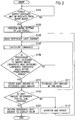
- FIG. 2 is a flowchart showing process procedures performed by the image reading apparatus 1.
- Step S101 when a power supply of the image reading apparatus 1 is switched on, or is recovered from a sleep mode (Step S101: YES), as an initialization operation, it is necessary to adjust the light amount of each of the light emitting elements 101 so that the light amount is appropriate for each line period.
- the line period is defined in accordance with image reading settings such as resolution, and is a reading interval when reading an original document line by line.
- the line period setting unit 11 in the controlling unit 10 performs an initial setting of a line period that is determined in advance among the plurality of the line periods (Step S103).
- the default value of the line period is stored in the storing unit 14. For example, a predefined longest line period of 400 ( ⁇ s) is set as a default value among 400 ( ⁇ s), 300 ( ⁇ s), and 200 ( ⁇ s) that can be set as the line period.
- the light amount setting unit 13 reads the reference light amount from the storing unit 14 (Step S105). For example, 40(%), 50(%), 60(%), 70(%), and 80(%) can be set as a reference light amount, and when the lowest value 40(%) is stored as the default value, the light amount setting unit 13 reads the stored 40(%) as the reference light amount. As will be described later, when the reference light amount is updated, the light amount setting unit 13 reads the updated reference light amount.
- the luminance calculating unit 12 calculates a luminance based on the reflected light amount received by each of the light receiving elements 107 in the line period set by the line period setting unit 11 (Step S107).
- the light amount setting unit 13 determines whether the percentage of the light receiving elements having the luminance that has exceeded a luminance threshold value is within a predetermined range (Step S109).
- FIGS. 3A to 3C are illustrative views explaining a determining process performed by the luminance calculating unit 12 in the image reading apparatus 1.
- a luminance that is calculated based on the light amount received by each of the light receiving elements 107 arranged in a line in the main scanning direction for the line period of 400 ( ⁇ s), which is the default value, is shown.
- the light amount setting unit 13 calculates the percentage of the light receiving elements having a luminance 301 that has exceeded a luminance threshold value 300 when the light amount (output) of each of the light emitting elements 101 is set to 40(%). Because the luminance 301 shown in FIG. 3A does not exceed the luminance threshold value 300, the percentage of the light receiving elements having the luminance that has exceeded the luminance threshold value is 0(%). As a result, the percentage is determined to be not within the predetermined range.
- the predetermined range is a range of the percentage of the light receiving elements when the sufficient luminance is obtained for appropriately reading an image in one line in the main scanning direction.
- the predetermined range is set to in advance, for example, 50(%) to 70(%).
- the percentage of the light receiving elements having the luminance that has exceeded the luminance threshold value is less than 50(%), the light amount for the entire one line in the main scanning direction is too small, causing the image formed by reading the original document to be a dark image.
- the percentage of the light receiving elements having the luminance that has exceeded the luminance threshold value exceeds 70(%), the light amount for the entire one line in the main scanning direction may become excessive, causing the color of the image formed by reading the original document to be unclear. Therefore, it is necessary to set in advance the range of the percentage of the light receiving elements having the luminance that exceeds the luminance threshold value so as to obtain the sufficient luminance for appropriately reading an image.
- Step S109 NO
- the light amount setting unit 13 increases the light amount by one level (Step S111).
- 40(%) is increased to 50(%) in the increments of 10(%).
- Step S107 the control is returned to Step S107, where each of the light emitting elements 101 is again caused to emit the light at the light amount increased by one level.
- the luminance calculating unit 12 calculates the luminance based on the light amount of the reflected light received by each of the light receiving elements 107 (Step S107), and the light amount setting unit 13 determines whether the percentage of the light receiving elements having the luminance that has exceeded the luminance threshold value is within the predetermined range (Step S109).
- the read image is too dark even when the light amount (output) of each of the light emitting elements 101 is set to 50(%), and in a luminance 302 when the light amount (output) of each of the light emitting elements 101 is 60(%), the percentage of the number L2 of the light receiving elements 107 having the luminance that has exceeded the luminance threshold value 300 with respect to the total number L1 of the light receiving elements 107 arranged in the main scanning direction, is within the predetermined range (50(%) to 70(%)).
- the light amount setting unit 13 determines that the percentage of the light receiving elements having the luminance that has exceeded the luminance threshold value is within the predetermined range (Step S109: YES).
- the light amount setting unit 13 Upon determining that the percentage of the light receiving elements having the luminance that has exceeded the luminance threshold value is within the predetermined range (Step S109: YES), the light amount setting unit 13 updates the reference light amount stored in the storing unit 14 with the set light amount as a new reference light amount (Step S113). In the example shown in FIG. 3A , the light amount (output) of 60(%) of each of the light emitting elements 101 is stored as the reference light amount.
- the light amount setting unit 13 determines whether the light amount is determined for all the line periods among the line periods 400 ( ⁇ s), 300 ( ⁇ s), and 200 ( ⁇ s) that can be set (Step S115).
- the light amount setting unit 13 shortens the line period (Step S117). For example, if the presently set line period is 400 (us), then 300 (us) is set as the line period, and if the presently set is 300 ( ⁇ s), then 200 ( ⁇ s) is set as the line period.
- Step S105 the control is returned to Step S105 where the light amount setting unit 13 reads the reference light amount from the storing unit 14 (Step S105), and then the processes at Steps S107, S109, S111, S113, S115, and S117 are performed.
- the reference light amount was updated at Step S113, after the shortening of the line period at Step S117, a light amount in which the percentage of the light receiving elements having the luminance that has exceeded the luminance threshold value is within the predetermined range can be determined by considering the light amount set for the previous line period as the reference light amount. Therefore, the light amount can be determined in a short time.
- FIG. 3B a luminance that is calculated based on the light amount received by each of the light receiving elements 107 that are arranged in a line in the main scanning direction for the line period of 300 ( ⁇ s) is shown.
- the light amount setting unit 13 calculates a luminance 313 when the light amount (output) of each of the light emitting elements 101 is set to 60(%), instead of calculating a luminance 311 when the light amount (output) of each of the light emitting elements 101 is set to 40(%) and a luminance 312 when the light amount (output) of each of the light emitting elements 101 is set to 50(%). Then, the light amount setting unit 13 calculates the percentage of the light receiving elements having the luminance 313 that has exceeded the luminance threshold value 300. Because the luminance 313 shown in FIG. 3B does not exceed the luminance threshold value 300, the percentage of the light receiving elements having the luminance that has exceeded the luminance threshold value is 0(%). As a result, the percentage is determined to be not within the predetermined range.
- the light amount setting unit 13 calculates a luminance 314 when the light amount (output) of each of the light emitting elements 101 is set to 70(%). Because the percentage of the number L3 of the light receiving elements 107 having the luminance 314 that has exceeded the luminance threshold value 300 with respect to the total number L1 of the light receiving elements 107 arranged in the main scanning direction, is within the predetermined range (50(%) to 70(%)), the light amount setting unit 13 determines that the percentage of the light receiving elements having the luminance that has exceeded the luminance threshold value is within the predetermined range. Accordingly, the light amount setting unit 13 stores the light amount (output) of 70(%) of each of the light emitting elements 101 as the reference light amount in the storing unit 14.
- the light amount setting unit 13 sets the light amount of each of the light emitting elements 101 so that the luminance calculated by the luminance calculating unit 12 is within the predetermined range. Therefore, because an appropriate light amount of each of the light emitting elements 101 can be set by setting the light amount in the previous line period as the reference light amount after the line period is changed, the light amount can be determined in a short time. In the example shown in FIG.
- the light amount setting unit 13 does not calculate the luminance 311 when the light amount (output) of each of the light emitting elements 101 is set to 40(%) and the luminance 312 when the light amount (output) of each of the light emitting elements 101 is set to 50(%), the light amount can be determined quickly.
- the light amount setting unit 13 reads the reference light amount from the storing unit 14 (Step S105), and then executes the processes of Steps S107, S109, S111, S113, S115, and S117.
- FIG. 3C a luminance that is calculated based on the light amount received by the light receiving elements 107 arranged in a line in the main scanning direction for the line period of 200 ( ⁇ s) is shown.
- the light amount setting unit 13 calculates a luminance 324 when the light amount (output) of each of the light emitting elements 101 is set to 70(%), instead of calculating a luminance 321 when the light amount (output) of each of the light emitting elements 101 is set to 40(%), a luminance 322 when the light amount (output) of each of the light emitting elements 101 is set to 50(%), and a luminance 323 when the light amount (output) of each of the light emitting elements 101 is set to 60(%).
- the light amount setting unit 13 calculates the percentage of the light receiving elements having the luminance 324 that has exceeded the luminance threshold value 300. Because the luminance 324 shown in FIG. 3C does not exceed the luminance threshold value 300, the percentage of the light receiving elements having the luminance that has exceeded the luminance threshold value is 0(%). As a result, the percentage is determined to be not within the predetermined range.
- the light amount setting unit 13 calculates a luminance 325 when the light amount (output) of each of the light emitting elements 101 is set to 80(%). Because the percentage of the number L4 of the light receiving elements having the luminance 325 that has exceeded the luminance threshold value 300 with respect to the total number L1 of the light receiving elements arranged in the main scanning direction, is within the predetermined range (50(%) to 70(%)), the light amount setting unit 13 determines that the percentage of the light receiving elements having the luminance that has exceeded the luminance threshold value is within the predetermined range.
- the light amount setting unit 13 does not calculate the luminance when the light amount (output) of each of the light emitting elements 101 is set to 40(%), 50(%) and 60(%), the light amount can be calculated quickly.
- Step S115 when the light amount setting unit 13 determines that the light amount is determined for all the line periods among the line periods of 400 ( ⁇ s), 300 ( ⁇ s), and 200 ( ⁇ s) that can be set (Step S115: YES), the reference light amount stored in the storing unit 14 is reset to the default value of 40(%) (Step S121).
- FIGS. 4A and 4B show the advantageous effects of the image reading apparatus 1 according to the embodiment of the present invention.
- FIG. 4A is a view showing a time taken for determining the light amount of the light emitting element in the conventional technology for the purpose of comparison.
- FIG. 4B is a view showing a time taken for determining the light amount of the light emitting element in the image reading apparatus 1.
- the light amount of the light emitting element 101 in the line period of 400 ( ⁇ s) is determined at a time point t2, from the time point t2 onwards, by setting the reference light amount to 40(%) and changing the light amount in the line period of 300 ( ⁇ s), 70(%) is determined to be the appropriate light amount. Therefore, because it is necessary to calculate the luminance each time when the reference light amount is set to 40(%), 50(%), 60(%), and 70(%), and determine whether the percentage of the light receiving elements having the luminance that has exceeded the luminance threshold value is within the predetermined range, determining the light amount of the light emitting element 101 for the line period of 300 ( ⁇ s) takes time up to a time point t3.
- determining the light amount of the light emitting element 101 for the line period of 200 ( ⁇ s) takes time up to a time point t4.
- the light amount for the light emitting elements 101 in one line period when 60(%) is determined as the light amount for the light emitting elements 101 in one line period, compared to the conventional technology, a part of the subsequent calculation process can be omitted. As a result, the light amount for the light emitting elements 101 for all the line periods can be determined in a short time.
- the light amount of the light emitting element 101 in the line period of 300 ( ⁇ s) can be determined at a time point t5, which is earlier than the time point t3 shown in FIG. 4A .
- the light amount of the light emitting element 101 in the line period of 200 ( ⁇ s) can be determined at a time point t6, which is earlier than the time point t4 shown in FIG. 4A .
- the light amount setting unit 13 causes the light emitting elements 101 to emit the light with gradually changing the reference light amount from the default value of the reference light amount stored in the storing unit 14 in each line period that is sequentially selected by the line period setting unit 11.
- the light amount setting unit 13 identifies the reference light amount so that the luminance calculated by the luminance calculating unit 12 is within the predetermined range, and causes the storing unit 14 to store the identified reference light amount as the default value of the reference light amount in the next line period.
- the luminance can be calculated by considering the set light amount as the reference light amount and it can be determined whether the percentage of the light receiving elements having the luminance that has exceeded the luminance threshold value is within the predetermined range in the other line periods.
- a part of the calculation process can be omitted and the appropriate light amount in each line period can be determined quickly.
- the predefined longest line period of 400 ( ⁇ s) is set as the default value among the line periods of 400 ( ⁇ s), 300 ( ⁇ s), and 200 ( ⁇ s) that can be set as the line period. Therefore, the appropriate light amount is determined by sequentially shortening the line period at Step S117, and increasing the light amount in each line period at Step S111.
- the light amount of the light emitting element 101 in the line period of 400 ( ⁇ s) is determined, and then the light amount of the light emitting element 101 in the line period of 300 (us) and the light amount of the light emitting element 101 in the line period of 200 ( ⁇ s) are determined sequentially.
- the appropriate light amount is determined while gradually shortening the line period when the longest line period is set as the default value, the light amount must always be larger than the light amount determined in the previous line period.
- the predefined longest line period of 400 ( ⁇ s) is set as the default value of the line period, the appropriate light amount is determined by sequentially shortening the line period at Step S117, and increasing the light amount in each line period at Step S111.
- the shortest line period can be set as the default value of the line period.
- a predefined shortest line period of 200 ( ⁇ s) is set as the default value among the line periods of 400 ( ⁇ s), 300 ( ⁇ s), and 200 ( ⁇ s) that can be set as the line period at Step S103. Therefore, the appropriate light amount can be determined by sequentially making longer the line period at Step S117, and decreasing the light amount in each line period at Step S111.
Landscapes
- Engineering & Computer Science (AREA)
- Multimedia (AREA)
- Signal Processing (AREA)
- Health & Medical Sciences (AREA)
- Biomedical Technology (AREA)
- General Health & Medical Sciences (AREA)
- Facsimile Scanning Arrangements (AREA)
- Facsimile Heads (AREA)
- Optical Systems Of Projection Type Copiers (AREA)
- Light Sources And Details Of Projection-Printing Devices (AREA)
- Control Or Security For Electrophotography (AREA)
Abstract
Description
- The present invention relates to an image reading apparatus that quickly determines an appropriate light amount for each line period.
- Image reading apparatuses include a light emitting element that emits a light, a light receiving element that receives the reflected light, and a reference density board. For example, when a power supply of an image reading apparatus is switched on, the light emitting element emits a light on the reference density board, and the light receiving element receives the light reflected by the reference density board. The image reading apparatus adjusts, based on the received light amount, the light amount emitted by the light emitting element.
- Because a line period differs for each image reading setting when the image reading apparatus requires many image reading settings (resolution and the like) to be made, it is necessary to set the light emitting element so that a light amount that is appropriate for each line period is emitted. The line period refers to a reading interval set for reading an original document line by line. When the line period is long, an image can be appropriately read even with a small light amount. On the other hand, when the line period is short, it is necessary to increase the light amount to appropriately read an image.
- Therefore, to appropriately read an image, for example, when the power supply is switched on, an appropriate light amount must be set for each image reading setting, in other words, for each line period.
- Patent Document 1 (Japanese Patent Application Laid-open No.
2013-73286 - However, in the above-described paper sheet recognition apparatus, when correcting the light amount emitted by the light emitting element according to the transporting speed of the banknote BL, it is necessary to determine an extent to which the light amount emitted by the light emitting element is to be corrected.
- For example, one approach is to, for each line period, emit a light from the light emitting element at a given light emitting amount, receive the reflected light with the light receiving element, calculate a luminance based on the received light amount, and determine the light emitting amount of the light emitting element so that the calculated luminance is within a predetermined range.
- In the above-described method, if the calculated luminance is not within the predetermined range when a light is emitted by the light emitting element at a given light emitting amount in a given line period, the light emitting amount is changed to determine an appropriate light emitting amount so that the luminance is within the predetermined range.
- In this manner, because the operation of determining an appropriate light emitting amount for each line period so that the luminance is within the predetermined range is performed by repeatedly performing (1) changing of the light emitting amount, (2) measurement of the received light amount, and (3) calculation of luminance, a considerable time is taken to determine an appropriate light amount for all the line periods.
- The present invention has been made in view of such circumstances, and it is an object of the present invention to provide an image reading apparatus that quickly determines an appropriate light amount for each line period.
- In order to achieve the above-described object, according to one aspect of the present invention, there is provided an image reading apparatus including a light emitting element that emits a light; a light receiving element that receives the light reflected by a reference board upon being emitted from the light emitting element; a line period setter that sequentially sets a line period from among a plurality of line periods having mutually different intervals of a light receiving start signal sent from the light receiving element; a luminance calculator that calculates a luminance based on a light amount received by the light receiving element in the line period set by the line period setter; a storage that stores therein a plurality of reference light amounts each of which is a reference light amount of the light emitted by the light emitting element; and a light amount setter that, in each line period, causes the light emitting element to emit the light with gradually changing the reference light amount from a reference light amount set as a default value among the plurality of reference light amounts stored in the storage, identifies a reference light amount so that the luminance calculated by the luminance calculator is within a predetermined range, sets the identified reference light amount as a default value for the next line period, and causes the storage to store that the identified reference light amount.
- According to one aspect of the present invention, for each line period, the light amount setter causes the light emitting element to emit the light with gradually changing the reference light amount from the reference light amount that is set as the default value among the plurality of reference light amounts that is stored in the storage, identifies a reference light amount so that the luminance calculated by the luminance calculator is within the predetermined range, sets the identified reference light amount as the default value in the next line period, and causes the storage to store the identified reference light amount. Therefore, upon setting the light amount of the light emitting element in a given line period, the luminance can be calculated by considering the set light amount as the reference light amount in the other line periods, and it can be determined whether the calculated luminance is within the predetermined range. Thus, compared to the conventional technology, a part of the process can be omitted, and the appropriate light amount in each line period can be determined quickly.
-
-
FIG. 1 is a structural diagram of an image reading apparatus according to an embodiment of the present invention. -
FIG. 2 is a flowchart showing process procedures performed by the image reading apparatus according to the embodiment of the present invention. -
FIG. 3A is an illustrative view explaining a determining process of a luminance calculating unit of the image reading apparatus according to the embodiment of the present invention, and depicts a luminance that is calculated based on a light amount received by each of light receiving elements arranged in a line in a main scanning direction for a line period set at a default value, 400 (µs). -
FIG. 3B is an illustrative view explaining the determining process of the luminance calculating unit of the image reading apparatus according to the embodiment of the present invention, and depicts a luminance that is calculated based on a light amount received by each of the light receiving elements arranged in a line in the main scanning direction for a line period of 300 (µs). -
FIG. 3C is an illustrative view explaining the determining process of the luminance calculating unit of the image reading apparatus according to the embodiment of the present invention, and depicts a luminance that is calculated based on a light amount received by each of the light receiving elements arranged in a line in the main scanning direction for a line period of 200 (µs). -
FIG. 4A is a view showing a time taken for determining a light amount of a light emitting element in the conventional technology. -
FIG. 4B is a view showing a time taken for determining a light amount of a light emitting element in the image reading apparatus according to the embodiment of the present invention. - Exemplary embodiments of an image reading apparatus according to the present invention will be described below. The following embodiments cite an apparatus and the like that realize the technical concept of the present invention as an example. However, the technical concept of the present invention regarding the arrangement of various components is not limited to such embodiments. The technical concept of the present invention can be modified within the scope of claims.
-
FIG. 1 is a structural diagram of the image reading apparatus according to an embodiment of the present invention. - As shown in
FIG. 1 , animage reading apparatus 1 includes aplaten 200, areading unit 100, and a controllingunit 10. - A white
reference density board 201 to be used for adjusting the light amount, and a colorless transparentdocument reading glass 202 to be used for reading an original document are arranged on theplaten 200. - The
reading unit 100 is arranged below theplaten 200. - The
reading unit 100 includes acarriage 103 that is movably supported by a guide rail (not shown) in a sub scanning direction (X1-X2 direction) along theplaten 200. Thecarriage 103 includes a plurality oflight emitting elements 101 that emits light, and a plurality ofreflective plates 102. When adjusting the light amount, thecarriage 103 is positioned below thereference density board 201 so that the light emitted from thelight emitting elements 101 is reflected from thereference density board 201. When reading an original document, thecarriage 103 is positioned below thedocument reading glass 202 so that the light emitted from thelight emitting elements 101 is reflected from the original document placed on thedocument reading glass 202, and reads the original document while moving line by line in the sub scanning direction. -
Reflective plates reflective plate 102 upon being emitted from each of thelight emitting elements 101. Each reflected light is reflected by thereflective plates converging lens 106. - The reflected light converged by the converging
lens 106 is received by a light receivingelement 107 of areceiving unit 108. - A plurality of the
light emitting elements 101 is arranged in a line in a main scanning direction (a direction orthogonal to the sub scanning direction, front - depth direction ofFIG. 1 ). Similarly, a plurality of thelight receiving elements 107 is arranged in a line in the main scanning direction. Thelight emitting elements 101 emit light simultaneously, and thelight receiving elements 107 receive the light reflected by thereflective plates 102 upon being emitted from thelight emitting elements 101. It is noted that the number of thelight emitting elements 101 may be one. - The controlling
unit 10 includes a lineperiod setting unit 11, aluminance calculating unit 12, a lightamount setting unit 13, and astoring unit 14. - The line
period setting unit 11 sequentially sets a line period from among a plurality of line periods having mutually different intervals of a light receiving start signal. - The
luminance calculating unit 12 calculates a luminance based on the reflected light amount received by each of thelight receiving elements 107 in the line period set by the lineperiod setting unit 11. - For each line period, the light
amount setting unit 13 causes thelight emitting elements 101 to simultaneously emit the light with gradually changing a reference light amount from a default value of the reference light amount stored in the storingunit 14, identifies a reference light amount so that the luminance calculated by theluminance calculating unit 12 is within a predetermined range, and causes the storingunit 14 to store the identified reference light amount as a default value of the reference light amount of light for the next line period. - The storing
unit 14 stores therein a plurality of reference light amounts that is a reference for the light amount emitted from each of thelight emitting elements 101. -
FIG. 2 is a flowchart showing process procedures performed by theimage reading apparatus 1. - As shown in
FIG. 2 , when a power supply of theimage reading apparatus 1 is switched on, or is recovered from a sleep mode (Step S101: YES), as an initialization operation, it is necessary to adjust the light amount of each of thelight emitting elements 101 so that the light amount is appropriate for each line period. As described above, the line period is defined in accordance with image reading settings such as resolution, and is a reading interval when reading an original document line by line. - The line
period setting unit 11 in the controllingunit 10 performs an initial setting of a line period that is determined in advance among the plurality of the line periods (Step S103). The default value of the line period is stored in the storingunit 14. For example, a predefined longest line period of 400 (µs) is set as a default value among 400 (µs), 300 (µs), and 200 (µs) that can be set as the line period. - The light
amount setting unit 13 reads the reference light amount from the storing unit 14 (Step S105). For example, 40(%), 50(%), 60(%), 70(%), and 80(%) can be set as a reference light amount, and when the lowest value 40(%) is stored as the default value, the lightamount setting unit 13 reads the stored 40(%) as the reference light amount. As will be described later, when the reference light amount is updated, the lightamount setting unit 13 reads the updated reference light amount. - The
luminance calculating unit 12 calculates a luminance based on the reflected light amount received by each of thelight receiving elements 107 in the line period set by the line period setting unit 11 (Step S107). - The light
amount setting unit 13 determines whether the percentage of the light receiving elements having the luminance that has exceeded a luminance threshold value is within a predetermined range (Step S109). -
FIGS. 3A to 3C are illustrative views explaining a determining process performed by theluminance calculating unit 12 in theimage reading apparatus 1. InFIG. 3A , a luminance that is calculated based on the light amount received by each of thelight receiving elements 107 arranged in a line in the main scanning direction for the line period of 400 (µs), which is the default value, is shown. - In the present embodiment, because a value of 40(%) is stored as the default value of the reference light amount, as shown in
FIG. 3A , the lightamount setting unit 13 calculates the percentage of the light receiving elements having aluminance 301 that has exceeded aluminance threshold value 300 when the light amount (output) of each of thelight emitting elements 101 is set to 40(%). Because theluminance 301 shown inFIG. 3A does not exceed theluminance threshold value 300, the percentage of the light receiving elements having the luminance that has exceeded the luminance threshold value is 0(%). As a result, the percentage is determined to be not within the predetermined range. The predetermined range is a range of the percentage of the light receiving elements when the sufficient luminance is obtained for appropriately reading an image in one line in the main scanning direction. The predetermined range is set to in advance, for example, 50(%) to 70(%). In other words, if the percentage of the light receiving elements having the luminance that has exceeded the luminance threshold value is less than 50(%), the light amount for the entire one line in the main scanning direction is too small, causing the image formed by reading the original document to be a dark image. On the other hand, if the percentage of the light receiving elements having the luminance that has exceeded the luminance threshold value exceeds 70(%), the light amount for the entire one line in the main scanning direction may become excessive, causing the color of the image formed by reading the original document to be unclear. Therefore, it is necessary to set in advance the range of the percentage of the light receiving elements having the luminance that exceeds the luminance threshold value so as to obtain the sufficient luminance for appropriately reading an image. - When it is determined that the percentage of the light receiving elements having the luminance that has exceeded the luminance threshold value is not within the predetermined range (Step S109: NO), it means that the read image is too dark when the light amount (output) of each of the
light emitting elements 101 is set to 40(%), and thus the lightamount setting unit 13 increases the light amount by one level (Step S111). In the example shown inFIG. 3A , 40(%) is increased to 50(%) in the increments of 10(%). - Next, the control is returned to Step S107, where each of the
light emitting elements 101 is again caused to emit the light at the light amount increased by one level. Theluminance calculating unit 12 then calculates the luminance based on the light amount of the reflected light received by each of the light receiving elements 107 (Step S107), and the lightamount setting unit 13 determines whether the percentage of the light receiving elements having the luminance that has exceeded the luminance threshold value is within the predetermined range (Step S109). - In the example shown in
FIG. 3A , the read image is too dark even when the light amount (output) of each of thelight emitting elements 101 is set to 50(%), and in aluminance 302 when the light amount (output) of each of thelight emitting elements 101 is 60(%), the percentage of the number L2 of thelight receiving elements 107 having the luminance that has exceeded theluminance threshold value 300 with respect to the total number L1 of thelight receiving elements 107 arranged in the main scanning direction, is within the predetermined range (50(%) to 70(%)). In such a situation, when the light amount (output) of each of thelight emitting elements 101 is 60(%), the lightamount setting unit 13 determines that the percentage of the light receiving elements having the luminance that has exceeded the luminance threshold value is within the predetermined range (Step S109: YES). - Upon determining that the percentage of the light receiving elements having the luminance that has exceeded the luminance threshold value is within the predetermined range (Step S109: YES), the light
amount setting unit 13 updates the reference light amount stored in the storingunit 14 with the set light amount as a new reference light amount (Step S113). In the example shown inFIG. 3A , the light amount (output) of 60(%) of each of thelight emitting elements 101 is stored as the reference light amount. - Next, the light
amount setting unit 13 determines whether the light amount is determined for all the line periods among the line periods 400 (µs), 300 (µs), and 200 (µs) that can be set (Step S115). - When it is determined that the light amount is not determined for all the line periods (Step S115: NO), the light
amount setting unit 13 shortens the line period (Step S117). For example, if the presently set line period is 400 (us), then 300 (us) is set as the line period, and if the presently set is 300 (µs), then 200 (µs) is set as the line period. - Then, the control is returned to Step S105 where the light
amount setting unit 13 reads the reference light amount from the storing unit 14 (Step S105), and then the processes at Steps S107, S109, S111, S113, S115, and S117 are performed. However, because the reference light amount was updated at Step S113, after the shortening of the line period at Step S117, a light amount in which the percentage of the light receiving elements having the luminance that has exceeded the luminance threshold value is within the predetermined range can be determined by considering the light amount set for the previous line period as the reference light amount. Therefore, the light amount can be determined in a short time. - In
FIG. 3B , a luminance that is calculated based on the light amount received by each of thelight receiving elements 107 that are arranged in a line in the main scanning direction for the line period of 300 (µs) is shown. - In this example, because a value of 60(%) is stored as the default value of the reference light amount, as shown in
FIG. 3B , the lightamount setting unit 13 calculates aluminance 313 when the light amount (output) of each of thelight emitting elements 101 is set to 60(%), instead of calculating aluminance 311 when the light amount (output) of each of thelight emitting elements 101 is set to 40(%) and aluminance 312 when the light amount (output) of each of thelight emitting elements 101 is set to 50(%). Then, the lightamount setting unit 13 calculates the percentage of the light receiving elements having theluminance 313 that has exceeded theluminance threshold value 300. Because theluminance 313 shown inFIG. 3B does not exceed theluminance threshold value 300, the percentage of the light receiving elements having the luminance that has exceeded the luminance threshold value is 0(%). As a result, the percentage is determined to be not within the predetermined range. - The light
amount setting unit 13 then calculates aluminance 314 when the light amount (output) of each of thelight emitting elements 101 is set to 70(%). Because the percentage of the number L3 of thelight receiving elements 107 having theluminance 314 that has exceeded theluminance threshold value 300 with respect to the total number L1 of thelight receiving elements 107 arranged in the main scanning direction, is within the predetermined range (50(%) to 70(%)), the lightamount setting unit 13 determines that the percentage of the light receiving elements having the luminance that has exceeded the luminance threshold value is within the predetermined range. Accordingly, the lightamount setting unit 13 stores the light amount (output) of 70(%) of each of thelight emitting elements 101 as the reference light amount in the storingunit 14. - In this manner, by reading the reference light amount from the storing
unit 14 and changing the read reference light amount, the lightamount setting unit 13 sets the light amount of each of thelight emitting elements 101 so that the luminance calculated by theluminance calculating unit 12 is within the predetermined range. Therefore, because an appropriate light amount of each of thelight emitting elements 101 can be set by setting the light amount in the previous line period as the reference light amount after the line period is changed, the light amount can be determined in a short time. In the example shown inFIG. 3B where the line period is set to 300 (µs), because the lightamount setting unit 13 does not calculate theluminance 311 when the light amount (output) of each of thelight emitting elements 101 is set to 40(%) and theluminance 312 when the light amount (output) of each of thelight emitting elements 101 is set to 50(%), the light amount can be determined quickly. - Furthermore, upon determining the light amount in the line period of 300 (µs) and then setting the line period to 200 (µs) by executing the processes of Steps S115 and S117, the light
amount setting unit 13 reads the reference light amount from the storing unit 14 (Step S105), and then executes the processes of Steps S107, S109, S111, S113, S115, and S117. - In
FIG. 3C , a luminance that is calculated based on the light amount received by thelight receiving elements 107 arranged in a line in the main scanning direction for the line period of 200 (µs) is shown. - In this example, because a value of 70(%) is stored as the default value of the reference light amount, as shown in
FIG. 3C , the lightamount setting unit 13 calculates aluminance 324 when the light amount (output) of each of thelight emitting elements 101 is set to 70(%), instead of calculating aluminance 321 when the light amount (output) of each of thelight emitting elements 101 is set to 40(%), aluminance 322 when the light amount (output) of each of thelight emitting elements 101 is set to 50(%), and aluminance 323 when the light amount (output) of each of thelight emitting elements 101 is set to 60(%). Then, the lightamount setting unit 13 calculates the percentage of the light receiving elements having theluminance 324 that has exceeded theluminance threshold value 300. Because theluminance 324 shown inFIG. 3C does not exceed theluminance threshold value 300, the percentage of the light receiving elements having the luminance that has exceeded the luminance threshold value is 0(%). As a result, the percentage is determined to be not within the predetermined range. - Next, the light
amount setting unit 13 calculates aluminance 325 when the light amount (output) of each of thelight emitting elements 101 is set to 80(%). Because the percentage of the number L4 of the light receiving elements having theluminance 325 that has exceeded theluminance threshold value 300 with respect to the total number L1 of the light receiving elements arranged in the main scanning direction, is within the predetermined range (50(%) to 70(%)), the lightamount setting unit 13 determines that the percentage of the light receiving elements having the luminance that has exceeded the luminance threshold value is within the predetermined range. - In this manner, in the example shown in
FIG. 3C where the line period is set to 200 (µs), because the lightamount setting unit 13 does not calculate the luminance when the light amount (output) of each of thelight emitting elements 101 is set to 40(%), 50(%) and 60(%), the light amount can be calculated quickly. - Referring again to
FIG. 2 , when the lightamount setting unit 13 determines that the light amount is determined for all the line periods among the line periods of 400 (µs), 300 (µs), and 200 (µs) that can be set (Step S115: YES), the reference light amount stored in the storingunit 14 is reset to the default value of 40(%) (Step S121). -
FIGS. 4A and 4B show the advantageous effects of theimage reading apparatus 1 according to the embodiment of the present invention.FIG. 4A is a view showing a time taken for determining the light amount of the light emitting element in the conventional technology for the purpose of comparison.FIG. 4B is a view showing a time taken for determining the light amount of the light emitting element in theimage reading apparatus 1. - As shown in
FIG. 4A , in the conventional technology, when the power supply is switched on at a time point t1, by setting the reference light amount to 40(%) at first and changing the light amount in the line period of 400 (µs), 60(%) is determined to be the appropriate light amount. - When the light amount of the
light emitting element 101 in the line period of 400 (µs) is determined at a time point t2, from the time point t2 onwards, by setting the reference light amount to 40(%) and changing the light amount in the line period of 300 (µs), 70(%) is determined to be the appropriate light amount. Therefore, because it is necessary to calculate the luminance each time when the reference light amount is set to 40(%), 50(%), 60(%), and 70(%), and determine whether the percentage of the light receiving elements having the luminance that has exceeded the luminance threshold value is within the predetermined range, determining the light amount of thelight emitting element 101 for the line period of 300 (µs) takes time up to a time point t3. - From the time point t3 onwards, by setting the reference light amount to 40(%) and changing the light amount in the line period of 200 (µs), 80(%) is determined to be the appropriate light amount. Therefore, because it is necessary to calculate the luminance each time when the reference light amount is set to 40(%), 50(%), 60(%), 70(%), and 80(%), and determine whether the percentage of the light receiving elements having the luminance that has exceeded the luminance threshold value is within the predetermined range, determining the light amount of the
light emitting element 101 for the line period of 200 (µs) takes time up to a time point t4. - On the other hand, as shown in
FIG. 4B , in theimage reading apparatus 1, when the power supply is switched on at a time point t1, by setting the reference light amount to 40(%) at first and changing the light amount in the line period of 400 (us), 60(%) is determined to be the appropriate light amount. Therefore, similar to the conventional technology, determining the light amount of thelight emitting element 101 for the line period of 400 (µs) takes time up to a time point t2. - However, when 60(%) is determined as the light amount for the
light emitting elements 101 in one line period, compared to the conventional technology, a part of the subsequent calculation process can be omitted. As a result, the light amount for thelight emitting elements 101 for all the line periods can be determined in a short time. - Specifically, as shown in
FIG. 4B , upon determining the light amount of thelight emitting element 101 in the line period of 400 (µs) at the time point t2, from the time point t2 onwards, by setting the reference light amount to 60(%) and changing the light amount in the line period of 300 (µs), 70(%) is determined to be the appropriate light amount. Therefore, because it is not necessary to calculate the luminance each time when the reference light amount is set to 40(%) and 50(%), and determine whether the percentage of the light receiving elements having the luminance that has exceeded the luminance threshold value is within the predetermined range, the light amount of thelight emitting element 101 in the line period of 300 (µs) can be determined at a time point t5, which is earlier than the time point t3 shown inFIG. 4A . - From the time point t5 onwards, by setting the reference light amount to 70(%) and changing the light amount in the line period of 200 (µs), 80(%) is determined to be the appropriate light amount. Therefore, because it is not necessary to calculate the luminance each time when the reference light amount is set to 40(%), 50(%), and 60(%), and determine whether the percentage of the light receiving elements having the luminance that has exceeded the luminance threshold value is within the predetermined range, the light amount of the
light emitting element 101 in the line period of 200 (µs) can be determined at a time point t6, which is earlier than the time point t4 shown inFIG. 4A . - As described above, according to the
image reading apparatus 1, the lightamount setting unit 13 causes thelight emitting elements 101 to emit the light with gradually changing the reference light amount from the default value of the reference light amount stored in the storingunit 14 in each line period that is sequentially selected by the lineperiod setting unit 11. The lightamount setting unit 13 identifies the reference light amount so that the luminance calculated by theluminance calculating unit 12 is within the predetermined range, and causes the storingunit 14 to store the identified reference light amount as the default value of the reference light amount in the next line period. Therefore, when the light amount of thelight emitting element 101 is set in a given line period, the luminance can be calculated by considering the set light amount as the reference light amount and it can be determined whether the percentage of the light receiving elements having the luminance that has exceeded the luminance threshold value is within the predetermined range in the other line periods. Thus, compared to the conventional technology, a part of the calculation process can be omitted and the appropriate light amount in each line period can be determined quickly. - In the flowchart shown in
FIG. 2 , at Step S103, the predefined longest line period of 400 (µs) is set as the default value among the line periods of 400 (µs), 300 (µs), and 200 (µs) that can be set as the line period. Therefore, the appropriate light amount is determined by sequentially shortening the line period at Step S117, and increasing the light amount in each line period at Step S111. - Therefore, in the example mentioned above, the light amount of the
light emitting element 101 in the line period of 400 (µs) is determined, and then the light amount of thelight emitting element 101 in the line period of 300 (us) and the light amount of thelight emitting element 101 in the line period of 200 (µs) are determined sequentially. - As described above, when the line period is long, an image can be appropriately read even with a small light amount, but when the line period is short, a large light amount is required to appropriately read the image.
- Therefore, because the appropriate light amount is determined while gradually shortening the line period when the longest line period is set as the default value, the light amount must always be larger than the light amount determined in the previous line period. In such a case, when the predefined longest line period of 400 (µs) is set as the default value of the line period, the appropriate light amount is determined by sequentially shortening the line period at Step S117, and increasing the light amount in each line period at Step S111.
- However, in the
image reading apparatus 1 according to the embodiment of the present invention, the shortest line period can be set as the default value of the line period. - In this case, in the flowchart shown in
FIG. 2 , a predefined shortest line period of 200 (µs) is set as the default value among the line periods of 400 (µs), 300 (µs), and 200 (µs) that can be set as the line period at Step S103. Therefore, the appropriate light amount can be determined by sequentially making longer the line period at Step S117, and decreasing the light amount in each line period at Step S111.
Claims (1)
- An image reading apparatus (1) comprising:a light emitting element (101) that emits a light;a light receiving element (107) that receives the light reflected by a reference board (201) upon being emitted from the light emitting element (101);a line period setter (11) that sequentially sets a line period from among a plurality of line periods having mutually different intervals of a light receiving start signal sent from the light receiving element (107);a luminance calculator (12) that calculates a luminance based on a light amount received by the light receiving element (107) in the line period set by the line period setter (11);a storage (14) that stores therein a plurality of reference light amounts each of which is a reference light amount of the light emitted by the light emitting element (101); anda light amount setter (13) that, in each line period, causes the light emitting element (101) to emit the light with gradually changing the reference light amount from a reference light amount set as a default value among the plurality of reference light amounts stored in the storage (14), identifies a reference light amount so that the luminance calculated by the luminance calculator (12) is within a predetermined range, sets the identified reference light amount as a default value for the next line period, and causes the storage (14) to store the identified reference light amount.
Applications Claiming Priority (1)
| Application Number | Priority Date | Filing Date | Title |
|---|---|---|---|
| JP2015233057A JP6630137B2 (en) | 2015-11-30 | 2015-11-30 | Image reading device |
Publications (2)
| Publication Number | Publication Date |
|---|---|
| EP3174278A1 true EP3174278A1 (en) | 2017-05-31 |
| EP3174278B1 EP3174278B1 (en) | 2018-08-22 |
Family
ID=57482162
Family Applications (1)
| Application Number | Title | Priority Date | Filing Date |
|---|---|---|---|
| EP16200881.7A Not-in-force EP3174278B1 (en) | 2015-11-30 | 2016-11-28 | Image reading apparatus |
Country Status (3)
| Country | Link |
|---|---|
| US (1) | US9894232B2 (en) |
| EP (1) | EP3174278B1 (en) |
| JP (1) | JP6630137B2 (en) |
Citations (4)
| Publication number | Priority date | Publication date | Assignee | Title |
|---|---|---|---|---|
| JP2001245111A (en) * | 2000-02-29 | 2001-09-07 | Canon Inc | Image reading apparatus and method |
| US20090296172A1 (en) * | 2008-05-30 | 2009-12-03 | Brother Kogyo Kabushiki Kaisha | Image reading device having line sensor performing pre-scan based on condition set for main-scan |
| US20100231991A1 (en) * | 2009-03-16 | 2010-09-16 | Brother Kogyo Kabushiki Kaisha | Image Reading Device |
| JP2013073286A (en) | 2011-09-27 | 2013-04-22 | Hitachi Omron Terminal Solutions Corp | Paper sheet identification device |
Family Cites Families (16)
| Publication number | Priority date | Publication date | Assignee | Title |
|---|---|---|---|---|
| JP2536094B2 (en) * | 1988-10-20 | 1996-09-18 | 富士ゼロックス株式会社 | Color image processing device |
| KR100413688B1 (en) * | 2001-09-04 | 2003-12-31 | 삼성전자주식회사 | Apparatus for controling of color registration and image density |
| JP4457976B2 (en) * | 2004-07-27 | 2010-04-28 | ブラザー工業株式会社 | Image reading apparatus and image reading method |
| JP2007033770A (en) * | 2005-07-26 | 2007-02-08 | Ricoh Co Ltd | Image forming apparatus |
| JP4433041B2 (en) * | 2007-11-16 | 2010-03-17 | ソニー株式会社 | Display device, image signal processing method, and program |
| US8388646B2 (en) * | 2008-02-22 | 2013-03-05 | Covidien Lp | Monocoque jaw design |
| US9046850B2 (en) * | 2011-02-04 | 2015-06-02 | Ricoh Company, Ltd. | Image forming apparatus capable of reducing image density irregularity |
| JP5349541B2 (en) * | 2011-06-16 | 2013-11-20 | シャープ株式会社 | Image reading apparatus and image forming apparatus |
| JP5481436B2 (en) * | 2011-06-30 | 2014-04-23 | 京セラドキュメントソリューションズ株式会社 | Image reading apparatus and image forming apparatus |
| WO2013054814A1 (en) * | 2011-10-11 | 2013-04-18 | 株式会社ニコン | Shape-measuring device, system for manufacturing structures, shape-measuring method, method for manufacturing structures, shape-measuring program |
| JP5817451B2 (en) * | 2011-11-10 | 2015-11-18 | 富士ゼロックス株式会社 | Detection apparatus, image forming apparatus, and program |
| JP2014083397A (en) * | 2012-10-26 | 2014-05-12 | Canon Inc | Ophthalmologic apparatus, control method thereof, and program |
| JP5968353B2 (en) * | 2014-03-27 | 2016-08-10 | 京セラドキュメントソリューションズ株式会社 | Inspection method for sheet detection apparatus, sheet detection apparatus, image processing apparatus, and inspection apparatus |
| JP6380197B2 (en) * | 2015-03-30 | 2018-08-29 | ブラザー工業株式会社 | Image reading device |
| JP6554973B2 (en) * | 2015-07-29 | 2019-08-07 | ブラザー工業株式会社 | Image reading device |
| JP6691683B2 (en) * | 2016-02-25 | 2020-05-13 | 株式会社リコー | Image density detecting apparatus, image forming apparatus, image density detecting method and image forming method |
-
2015
- 2015-11-30 JP JP2015233057A patent/JP6630137B2/en active Active
-
2016
- 2016-11-21 US US15/357,062 patent/US9894232B2/en active Active
- 2016-11-28 EP EP16200881.7A patent/EP3174278B1/en not_active Not-in-force
Patent Citations (4)
| Publication number | Priority date | Publication date | Assignee | Title |
|---|---|---|---|---|
| JP2001245111A (en) * | 2000-02-29 | 2001-09-07 | Canon Inc | Image reading apparatus and method |
| US20090296172A1 (en) * | 2008-05-30 | 2009-12-03 | Brother Kogyo Kabushiki Kaisha | Image reading device having line sensor performing pre-scan based on condition set for main-scan |
| US20100231991A1 (en) * | 2009-03-16 | 2010-09-16 | Brother Kogyo Kabushiki Kaisha | Image Reading Device |
| JP2013073286A (en) | 2011-09-27 | 2013-04-22 | Hitachi Omron Terminal Solutions Corp | Paper sheet identification device |
Also Published As
| Publication number | Publication date |
|---|---|
| US20170155789A1 (en) | 2017-06-01 |
| JP2017103516A (en) | 2017-06-08 |
| JP6630137B2 (en) | 2020-01-15 |
| EP3174278B1 (en) | 2018-08-22 |
| US9894232B2 (en) | 2018-02-13 |
Similar Documents
| Publication | Publication Date | Title |
|---|---|---|
| US9931828B2 (en) | Three-dimensional printing device | |
| US20140218772A1 (en) | Document reading apparatus | |
| US20170004754A1 (en) | Dot correction method and system for led display device | |
| US9511589B2 (en) | Ink jet printer | |
| US9986129B2 (en) | Scanner and image production method for sequentially storing image correction value in plurality of storage regions | |
| US20180341208A1 (en) | Image forming apparatus, image forming system, and image formation control program | |
| US9894232B2 (en) | Image reading apparatus | |
| CN103021078B (en) | A paper category identifying device | |
| US20150277324A1 (en) | Image Forming Apparatus and Method for Adjusting Forming Condition of Image Forming Apparatus | |
| US20180294618A1 (en) | Laser apparatus including plurality of laser modules | |
| US20180152595A1 (en) | Document reading apparatus | |
| US20060103898A1 (en) | Image reading apparatus, image forming apparatus, control method, and program | |
| US20170366693A1 (en) | Image reading apparatus, image reading method, and non-transitory computer readable medium | |
| US20210306520A1 (en) | Image reading apparatus and image forming apparatus | |
| JP5507058B2 (en) | Parameter setting method for optical recognition apparatus and optical recognition apparatus | |
| JP5962097B2 (en) | Recording material discrimination sensor and image forming apparatus | |
| CN117812781A (en) | A light source control method, 3D printing equipment and storage medium | |
| US20210321018A1 (en) | Information processing apparatus, information processing method, and storage medium | |
| JP2013197131A (en) | Semiconductor laser driving device, method for driving semiconductor laser and electronic equipment | |
| US12420571B2 (en) | Printing apparatus, control method, and storage medium | |
| JP7587135B2 (en) | Printing device | |
| JP2016099561A5 (en) | ||
| US20260113412A1 (en) | Inkjet printing apparatus, inkjet printing method, and storage medium | |
| JP4720750B2 (en) | Image reading device | |
| JP2010056686A (en) | Image reading device and program |
Legal Events
| Date | Code | Title | Description |
|---|---|---|---|
| PUAI | Public reference made under article 153(3) epc to a published international application that has entered the european phase |
Free format text: ORIGINAL CODE: 0009012 |
|
| 17P | Request for examination filed |
Effective date: 20161128 |
|
| AK | Designated contracting states |
Kind code of ref document: A1 Designated state(s): AL AT BE BG CH CY CZ DE DK EE ES FI FR GB GR HR HU IE IS IT LI LT LU LV MC MK MT NL NO PL PT RO RS SE SI SK SM TR |
|
| AX | Request for extension of the european patent |
Extension state: BA ME |
|
| GRAP | Despatch of communication of intention to grant a patent |
Free format text: ORIGINAL CODE: EPIDOSNIGR1 |
|
| RIC1 | Information provided on ipc code assigned before grant |
Ipc: H04N 1/028 20060101ALI20180413BHEP Ipc: H04N 1/407 20060101ALI20180413BHEP Ipc: H04N 1/00 20060101ALI20180413BHEP Ipc: H04N 1/10 20060101ALN20180413BHEP Ipc: H04N 1/04 20060101ALI20180413BHEP Ipc: H04N 1/40 20060101AFI20180413BHEP |
|
| INTG | Intention to grant announced |
Effective date: 20180502 |
|
| RAP1 | Party data changed (applicant data changed or rights of an application transferred) |
Owner name: RISO KAGAKU CORPORATION |
|
| RIN1 | Information on inventor provided before grant (corrected) |
Inventor name: SHIOKAWA, MITSUHARU |
|
| GRAS | Grant fee paid |
Free format text: ORIGINAL CODE: EPIDOSNIGR3 |
|
| GRAA | (expected) grant |
Free format text: ORIGINAL CODE: 0009210 |
|
| AK | Designated contracting states |
Kind code of ref document: B1 Designated state(s): AL AT BE BG CH CY CZ DE DK EE ES FI FR GB GR HR HU IE IS IT LI LT LU LV MC MK MT NL NO PL PT RO RS SE SI SK SM TR |
|
| REG | Reference to a national code |
Ref country code: GB Ref legal event code: FG4D |
|
| REG | Reference to a national code |
Ref country code: CH Ref legal event code: EP |
|
| REG | Reference to a national code |
Ref country code: AT Ref legal event code: REF Ref document number: 1033843 Country of ref document: AT Kind code of ref document: T Effective date: 20180915 |
|
| REG | Reference to a national code |
Ref country code: IE Ref legal event code: FG4D |
|
| REG | Reference to a national code |
Ref country code: DE Ref legal event code: R096 Ref document number: 602016004982 Country of ref document: DE |
|
| REG | Reference to a national code |
Ref country code: NL Ref legal event code: MP Effective date: 20180822 |
|
| REG | Reference to a national code |
Ref country code: LT Ref legal event code: MG4D |
|
| PG25 | Lapsed in a contracting state [announced via postgrant information from national office to epo] |
Ref country code: FI Free format text: LAPSE BECAUSE OF FAILURE TO SUBMIT A TRANSLATION OF THE DESCRIPTION OR TO PAY THE FEE WITHIN THE PRESCRIBED TIME-LIMIT Effective date: 20180822 Ref country code: LT Free format text: LAPSE BECAUSE OF FAILURE TO SUBMIT A TRANSLATION OF THE DESCRIPTION OR TO PAY THE FEE WITHIN THE PRESCRIBED TIME-LIMIT Effective date: 20180822 Ref country code: IS Free format text: LAPSE BECAUSE OF FAILURE TO SUBMIT A TRANSLATION OF THE DESCRIPTION OR TO PAY THE FEE WITHIN THE PRESCRIBED TIME-LIMIT Effective date: 20181222 Ref country code: RS Free format text: LAPSE BECAUSE OF FAILURE TO SUBMIT A TRANSLATION OF THE DESCRIPTION OR TO PAY THE FEE WITHIN THE PRESCRIBED TIME-LIMIT Effective date: 20180822 Ref country code: NL Free format text: LAPSE BECAUSE OF FAILURE TO SUBMIT A TRANSLATION OF THE DESCRIPTION OR TO PAY THE FEE WITHIN THE PRESCRIBED TIME-LIMIT Effective date: 20180822 Ref country code: GR Free format text: LAPSE BECAUSE OF FAILURE TO SUBMIT A TRANSLATION OF THE DESCRIPTION OR TO PAY THE FEE WITHIN THE PRESCRIBED TIME-LIMIT Effective date: 20181123 Ref country code: NO Free format text: LAPSE BECAUSE OF FAILURE TO SUBMIT A TRANSLATION OF THE DESCRIPTION OR TO PAY THE FEE WITHIN THE PRESCRIBED TIME-LIMIT Effective date: 20181122 Ref country code: BG Free format text: LAPSE BECAUSE OF FAILURE TO SUBMIT A TRANSLATION OF THE DESCRIPTION OR TO PAY THE FEE WITHIN THE PRESCRIBED TIME-LIMIT Effective date: 20181122 Ref country code: SE Free format text: LAPSE BECAUSE OF FAILURE TO SUBMIT A TRANSLATION OF THE DESCRIPTION OR TO PAY THE FEE WITHIN THE PRESCRIBED TIME-LIMIT Effective date: 20180822 |
|
| REG | Reference to a national code |
Ref country code: AT Ref legal event code: MK05 Ref document number: 1033843 Country of ref document: AT Kind code of ref document: T Effective date: 20180822 |
|
| PG25 | Lapsed in a contracting state [announced via postgrant information from national office to epo] |
Ref country code: AL Free format text: LAPSE BECAUSE OF FAILURE TO SUBMIT A TRANSLATION OF THE DESCRIPTION OR TO PAY THE FEE WITHIN THE PRESCRIBED TIME-LIMIT Effective date: 20180822 Ref country code: LV Free format text: LAPSE BECAUSE OF FAILURE TO SUBMIT A TRANSLATION OF THE DESCRIPTION OR TO PAY THE FEE WITHIN THE PRESCRIBED TIME-LIMIT Effective date: 20180822 Ref country code: HR Free format text: LAPSE BECAUSE OF FAILURE TO SUBMIT A TRANSLATION OF THE DESCRIPTION OR TO PAY THE FEE WITHIN THE PRESCRIBED TIME-LIMIT Effective date: 20180822 |
|
| PG25 | Lapsed in a contracting state [announced via postgrant information from national office to epo] |
Ref country code: ES Free format text: LAPSE BECAUSE OF FAILURE TO SUBMIT A TRANSLATION OF THE DESCRIPTION OR TO PAY THE FEE WITHIN THE PRESCRIBED TIME-LIMIT Effective date: 20180822 Ref country code: PL Free format text: LAPSE BECAUSE OF FAILURE TO SUBMIT A TRANSLATION OF THE DESCRIPTION OR TO PAY THE FEE WITHIN THE PRESCRIBED TIME-LIMIT Effective date: 20180822 Ref country code: EE Free format text: LAPSE BECAUSE OF FAILURE TO SUBMIT A TRANSLATION OF THE DESCRIPTION OR TO PAY THE FEE WITHIN THE PRESCRIBED TIME-LIMIT Effective date: 20180822 Ref country code: RO Free format text: LAPSE BECAUSE OF FAILURE TO SUBMIT A TRANSLATION OF THE DESCRIPTION OR TO PAY THE FEE WITHIN THE PRESCRIBED TIME-LIMIT Effective date: 20180822 Ref country code: IT Free format text: LAPSE BECAUSE OF FAILURE TO SUBMIT A TRANSLATION OF THE DESCRIPTION OR TO PAY THE FEE WITHIN THE PRESCRIBED TIME-LIMIT Effective date: 20180822 Ref country code: AT Free format text: LAPSE BECAUSE OF FAILURE TO SUBMIT A TRANSLATION OF THE DESCRIPTION OR TO PAY THE FEE WITHIN THE PRESCRIBED TIME-LIMIT Effective date: 20180822 Ref country code: CZ Free format text: LAPSE BECAUSE OF FAILURE TO SUBMIT A TRANSLATION OF THE DESCRIPTION OR TO PAY THE FEE WITHIN THE PRESCRIBED TIME-LIMIT Effective date: 20180822 |
|
| REG | Reference to a national code |
Ref country code: DE Ref legal event code: R097 Ref document number: 602016004982 Country of ref document: DE |
|
| PG25 | Lapsed in a contracting state [announced via postgrant information from national office to epo] |
Ref country code: DK Free format text: LAPSE BECAUSE OF FAILURE TO SUBMIT A TRANSLATION OF THE DESCRIPTION OR TO PAY THE FEE WITHIN THE PRESCRIBED TIME-LIMIT Effective date: 20180822 Ref country code: SM Free format text: LAPSE BECAUSE OF FAILURE TO SUBMIT A TRANSLATION OF THE DESCRIPTION OR TO PAY THE FEE WITHIN THE PRESCRIBED TIME-LIMIT Effective date: 20180822 Ref country code: SK Free format text: LAPSE BECAUSE OF FAILURE TO SUBMIT A TRANSLATION OF THE DESCRIPTION OR TO PAY THE FEE WITHIN THE PRESCRIBED TIME-LIMIT Effective date: 20180822 |
|
| PLBE | No opposition filed within time limit |
Free format text: ORIGINAL CODE: 0009261 |
|
| STAA | Information on the status of an ep patent application or granted ep patent |
Free format text: STATUS: NO OPPOSITION FILED WITHIN TIME LIMIT |
|
| 26N | No opposition filed |
Effective date: 20190523 |
|
| PG25 | Lapsed in a contracting state [announced via postgrant information from national office to epo] |
Ref country code: LU Free format text: LAPSE BECAUSE OF NON-PAYMENT OF DUE FEES Effective date: 20181128 Ref country code: MC Free format text: LAPSE BECAUSE OF FAILURE TO SUBMIT A TRANSLATION OF THE DESCRIPTION OR TO PAY THE FEE WITHIN THE PRESCRIBED TIME-LIMIT Effective date: 20180822 |
|
| REG | Reference to a national code |
Ref country code: BE Ref legal event code: MM Effective date: 20181130 |
|
| REG | Reference to a national code |
Ref country code: IE Ref legal event code: MM4A |
|
| PG25 | Lapsed in a contracting state [announced via postgrant information from national office to epo] |
Ref country code: SI Free format text: LAPSE BECAUSE OF FAILURE TO SUBMIT A TRANSLATION OF THE DESCRIPTION OR TO PAY THE FEE WITHIN THE PRESCRIBED TIME-LIMIT Effective date: 20180822 |
|
| PG25 | Lapsed in a contracting state [announced via postgrant information from national office to epo] |
Ref country code: IE Free format text: LAPSE BECAUSE OF NON-PAYMENT OF DUE FEES Effective date: 20181128 |
|
| PG25 | Lapsed in a contracting state [announced via postgrant information from national office to epo] |
Ref country code: BE Free format text: LAPSE BECAUSE OF NON-PAYMENT OF DUE FEES Effective date: 20181130 |
|
| PG25 | Lapsed in a contracting state [announced via postgrant information from national office to epo] |
Ref country code: MT Free format text: LAPSE BECAUSE OF NON-PAYMENT OF DUE FEES Effective date: 20181128 |
|
| PG25 | Lapsed in a contracting state [announced via postgrant information from national office to epo] |
Ref country code: TR Free format text: LAPSE BECAUSE OF FAILURE TO SUBMIT A TRANSLATION OF THE DESCRIPTION OR TO PAY THE FEE WITHIN THE PRESCRIBED TIME-LIMIT Effective date: 20180822 |
|
| PG25 | Lapsed in a contracting state [announced via postgrant information from national office to epo] |
Ref country code: PT Free format text: LAPSE BECAUSE OF FAILURE TO SUBMIT A TRANSLATION OF THE DESCRIPTION OR TO PAY THE FEE WITHIN THE PRESCRIBED TIME-LIMIT Effective date: 20180822 |
|
| PG25 | Lapsed in a contracting state [announced via postgrant information from national office to epo] |
Ref country code: HU Free format text: LAPSE BECAUSE OF FAILURE TO SUBMIT A TRANSLATION OF THE DESCRIPTION OR TO PAY THE FEE WITHIN THE PRESCRIBED TIME-LIMIT; INVALID AB INITIO Effective date: 20161128 Ref country code: CY Free format text: LAPSE BECAUSE OF FAILURE TO SUBMIT A TRANSLATION OF THE DESCRIPTION OR TO PAY THE FEE WITHIN THE PRESCRIBED TIME-LIMIT Effective date: 20180822 Ref country code: MK Free format text: LAPSE BECAUSE OF NON-PAYMENT OF DUE FEES Effective date: 20180822 |
|
| REG | Reference to a national code |
Ref country code: CH Ref legal event code: PL |
|
| PG25 | Lapsed in a contracting state [announced via postgrant information from national office to epo] |
Ref country code: LI Free format text: LAPSE BECAUSE OF NON-PAYMENT OF DUE FEES Effective date: 20191130 Ref country code: CH Free format text: LAPSE BECAUSE OF NON-PAYMENT OF DUE FEES Effective date: 20191130 |
|
| PGFP | Annual fee paid to national office [announced via postgrant information from national office to epo] |
Ref country code: DE Payment date: 20211122 Year of fee payment: 6 Ref country code: FR Payment date: 20211124 Year of fee payment: 6 Ref country code: GB Payment date: 20211123 Year of fee payment: 6 |
|
| REG | Reference to a national code |
Ref country code: DE Ref legal event code: R119 Ref document number: 602016004982 Country of ref document: DE |
|
| GBPC | Gb: european patent ceased through non-payment of renewal fee |
Effective date: 20221128 |
|
| PG25 | Lapsed in a contracting state [announced via postgrant information from national office to epo] |
Ref country code: GB Free format text: LAPSE BECAUSE OF NON-PAYMENT OF DUE FEES Effective date: 20221128 Ref country code: DE Free format text: LAPSE BECAUSE OF NON-PAYMENT OF DUE FEES Effective date: 20230601 |
|
| PG25 | Lapsed in a contracting state [announced via postgrant information from national office to epo] |
Ref country code: FR Free format text: LAPSE BECAUSE OF NON-PAYMENT OF DUE FEES Effective date: 20221130 |