EP3174164A1 - Tf card connector capable of installing nano-sim card, and mobile phone - Google Patents
Tf card connector capable of installing nano-sim card, and mobile phone Download PDFInfo
- Publication number
- EP3174164A1 EP3174164A1 EP15747350.5A EP15747350A EP3174164A1 EP 3174164 A1 EP3174164 A1 EP 3174164A1 EP 15747350 A EP15747350 A EP 15747350A EP 3174164 A1 EP3174164 A1 EP 3174164A1
- Authority
- EP
- European Patent Office
- Prior art keywords
- card
- nano
- disposed
- sim card
- installing
- Prior art date
- Legal status (The legal status is an assumption and is not a legal conclusion. Google has not performed a legal analysis and makes no representation as to the accuracy of the status listed.)
- Granted
Links
Images
Classifications
-
- H—ELECTRICITY
- H01—ELECTRIC ELEMENTS
- H01R—ELECTRICALLY-CONDUCTIVE CONNECTIONS; STRUCTURAL ASSOCIATIONS OF A PLURALITY OF MUTUALLY-INSULATED ELECTRICAL CONNECTING ELEMENTS; COUPLING DEVICES; CURRENT COLLECTORS
- H01R27/00—Coupling parts adapted for co-operation with two or more dissimilar counterparts
-
- G—PHYSICS
- G06—COMPUTING OR CALCULATING; COUNTING
- G06K—GRAPHICAL DATA READING; PRESENTATION OF DATA; RECORD CARRIERS; HANDLING RECORD CARRIERS
- G06K13/00—Conveying record carriers from one station to another, e.g. from stack to punching mechanism
- G06K13/02—Conveying record carriers from one station to another, e.g. from stack to punching mechanism the record carrier having longitudinal dimension comparable with transverse dimension, e.g. punched card
- G06K13/08—Feeding or discharging cards
-
- G—PHYSICS
- G06—COMPUTING OR CALCULATING; COUNTING
- G06K—GRAPHICAL DATA READING; PRESENTATION OF DATA; RECORD CARRIERS; HANDLING RECORD CARRIERS
- G06K13/00—Conveying record carriers from one station to another, e.g. from stack to punching mechanism
- G06K13/02—Conveying record carriers from one station to another, e.g. from stack to punching mechanism the record carrier having longitudinal dimension comparable with transverse dimension, e.g. punched card
- G06K13/08—Feeding or discharging cards
- G06K13/0806—Feeding or discharging cards using an arrangement for ejection of an inserted card
- G06K13/0812—Feeding or discharging cards using an arrangement for ejection of an inserted card the ejection arrangement utilizing a push bar for manipulation by hand in order to eject the inserted card
-
- G—PHYSICS
- G06—COMPUTING OR CALCULATING; COUNTING
- G06K—GRAPHICAL DATA READING; PRESENTATION OF DATA; RECORD CARRIERS; HANDLING RECORD CARRIERS
- G06K7/00—Methods or arrangements for sensing record carriers, e.g. for reading patterns
- G06K7/0013—Methods or arrangements for sensing record carriers, e.g. for reading patterns by galvanic contacts, e.g. card connectors for ISO-7816 compliant smart cards or memory cards, e.g. SD card readers
- G06K7/0021—Methods or arrangements for sensing record carriers, e.g. for reading patterns by galvanic contacts, e.g. card connectors for ISO-7816 compliant smart cards or memory cards, e.g. SD card readers for reading/sensing record carriers having surface contacts
-
- H—ELECTRICITY
- H01—ELECTRIC ELEMENTS
- H01R—ELECTRICALLY-CONDUCTIVE CONNECTIONS; STRUCTURAL ASSOCIATIONS OF A PLURALITY OF MUTUALLY-INSULATED ELECTRICAL CONNECTING ELEMENTS; COUPLING DEVICES; CURRENT COLLECTORS
- H01R12/00—Structural associations of a plurality of mutually-insulated electrical connecting elements, specially adapted for printed circuits, e.g. printed circuit boards [PCB], flat or ribbon cables, or like generally planar structures, e.g. terminal strips, terminal blocks; Coupling devices specially adapted for printed circuits, flat or ribbon cables, or like generally planar structures; Terminals specially adapted for contact with, or insertion into, printed circuits, flat or ribbon cables, or like generally planar structures
- H01R12/70—Coupling devices
- H01R12/71—Coupling devices for rigid printing circuits or like structures
- H01R12/712—Coupling devices for rigid printing circuits or like structures co-operating with the surface of the printed circuit or with a coupling device exclusively provided on the surface of the printed circuit
- H01R12/716—Coupling device provided on the PCB
-
- H—ELECTRICITY
- H01—ELECTRIC ELEMENTS
- H01R—ELECTRICALLY-CONDUCTIVE CONNECTIONS; STRUCTURAL ASSOCIATIONS OF A PLURALITY OF MUTUALLY-INSULATED ELECTRICAL CONNECTING ELEMENTS; COUPLING DEVICES; CURRENT COLLECTORS
- H01R12/00—Structural associations of a plurality of mutually-insulated electrical connecting elements, specially adapted for printed circuits, e.g. printed circuit boards [PCB], flat or ribbon cables, or like generally planar structures, e.g. terminal strips, terminal blocks; Coupling devices specially adapted for printed circuits, flat or ribbon cables, or like generally planar structures; Terminals specially adapted for contact with, or insertion into, printed circuits, flat or ribbon cables, or like generally planar structures
- H01R12/70—Coupling devices
- H01R12/71—Coupling devices for rigid printing circuits or like structures
- H01R12/72—Coupling devices for rigid printing circuits or like structures coupling with the edge of the rigid printed circuits or like structures
- H01R12/73—Coupling devices for rigid printing circuits or like structures coupling with the edge of the rigid printed circuits or like structures connecting to other rigid printed circuits or like structures
-
- H—ELECTRICITY
- H01—ELECTRIC ELEMENTS
- H01R—ELECTRICALLY-CONDUCTIVE CONNECTIONS; STRUCTURAL ASSOCIATIONS OF A PLURALITY OF MUTUALLY-INSULATED ELECTRICAL CONNECTING ELEMENTS; COUPLING DEVICES; CURRENT COLLECTORS
- H01R13/00—Details of coupling devices of the kinds covered by groups H01R12/70 or H01R24/00 - H01R33/00
- H01R13/46—Bases; Cases
- H01R13/514—Bases; Cases composed as a modular blocks or assembly, i.e. composed of co-operating parts provided with contact members or holding contact members between them
-
- H—ELECTRICITY
- H01—ELECTRIC ELEMENTS
- H01R—ELECTRICALLY-CONDUCTIVE CONNECTIONS; STRUCTURAL ASSOCIATIONS OF A PLURALITY OF MUTUALLY-INSULATED ELECTRICAL CONNECTING ELEMENTS; COUPLING DEVICES; CURRENT COLLECTORS
- H01R27/00—Coupling parts adapted for co-operation with two or more dissimilar counterparts
- H01R27/02—Coupling parts adapted for co-operation with two or more dissimilar counterparts for simultaneous co-operation with two or more dissimilar counterparts
-
- G—PHYSICS
- G06—COMPUTING OR CALCULATING; COUNTING
- G06K—GRAPHICAL DATA READING; PRESENTATION OF DATA; RECORD CARRIERS; HANDLING RECORD CARRIERS
- G06K13/00—Conveying record carriers from one station to another, e.g. from stack to punching mechanism
- G06K13/02—Conveying record carriers from one station to another, e.g. from stack to punching mechanism the record carrier having longitudinal dimension comparable with transverse dimension, e.g. punched card
- G06K13/08—Feeding or discharging cards
- G06K13/085—Feeding or discharging cards using an arrangement for locking the inserted card
- G06K13/0862—Feeding or discharging cards using an arrangement for locking the inserted card the locking arrangement being of the rotate-slide and lock type, such as, e.g. common in mobile phones
-
- H—ELECTRICITY
- H01—ELECTRIC ELEMENTS
- H01R—ELECTRICALLY-CONDUCTIVE CONNECTIONS; STRUCTURAL ASSOCIATIONS OF A PLURALITY OF MUTUALLY-INSULATED ELECTRICAL CONNECTING ELEMENTS; COUPLING DEVICES; CURRENT COLLECTORS
- H01R12/00—Structural associations of a plurality of mutually-insulated electrical connecting elements, specially adapted for printed circuits, e.g. printed circuit boards [PCB], flat or ribbon cables, or like generally planar structures, e.g. terminal strips, terminal blocks; Coupling devices specially adapted for printed circuits, flat or ribbon cables, or like generally planar structures; Terminals specially adapted for contact with, or insertion into, printed circuits, flat or ribbon cables, or like generally planar structures
- H01R12/70—Coupling devices
- H01R12/71—Coupling devices for rigid printing circuits or like structures
- H01R12/72—Coupling devices for rigid printing circuits or like structures coupling with the edge of the rigid printed circuits or like structures
- H01R12/721—Coupling devices for rigid printing circuits or like structures coupling with the edge of the rigid printed circuits or like structures cooperating directly with the edge of the rigid printed circuits
Definitions
- the present invention relates to a connector installed in the mobile phone, and more particularly to a TF card connector which is capable of installing a Nano-SIM card and a mobile phone thereof.
- one objective of the present invention is to provide a TF card and the Nano-SIM card in the TF card connector which is capable of installing a Nano-SIM card and a mobile phone thereof for increasing the functions of the TF card connector to allow the TF card connector to be installed by TF card and Nano-SIM card.
- the present invention employs the following technical scheme.
- a TF card connector which is capable of installing a Nano-SIM card, comprises a terminal retaining base, a first card slot disposed on the terminal retaining base and adapted to a TF card, and a plurality of first conducting terminals disposed on the terminal retaining base wherein a plurality of first ends of the first conducting terminals are disposed in the first card slot for connecting to the TF card and a plurality of second ends of the first conducting terminals are disposed in one side of the terminal retaining base for connecting to a main board of the mobile phone, wherein the TF card connector further comprises:
- a second card slot disposed on the terminal retaining base and adapted to a Nano-SIM card, and a plurality of second conducting terminals disposed on the terminal retaining base wherein a plurality of first ends of the second conducting terminals are disposed in the second card slot for connecting to the Nano-SIM card and a plurality of second ends of the second conducting terminals are disposed in one side of the terminal retaining base for connecting to the main board of the mobile phone; a pushing structure disposed on the terminal retaining base; and a plurality of embossment structures disposed on the terminal retaining base.
- the TF card connector which is capable of installing the Nano-SIM card further comprises the Nano-SIM card identification switch disposed on the terminal retaining base for closing the Nano-SIM card identification switch when the Nano-SIM card is inserted.
- the TF card connector which is capable of installing the Nano-SIM card further comprises a TF card identification switch disposed on the terminal retaining base for closing the TF card identification switch when the TF card is inserted.
- the second ends of the first conducting terminals and the second ends of the second conducting terminals are disposed respectively in the same side of the terminal retaining base.
- the second ends of the first conducting terminals and the second ends of the second conducting terminals are disposed respectively in the different sides of the terminal retaining base.
- the second card slot is opened and disposed on a bottom surface of the first card slot.
- TF card connector which is capable of installing the Nano-SIM card
- two sides of the second card slot and the first card slot are overlapped and eight second conducting terminals are disposed on the TF card connector which is capable of installing the Nano-SIM card.
- the present invention employs the following technical scheme.
- a TF card connector which is capable of installing a Nano-SIM card, comprises a terminal retaining base, a first card slot disposed on the terminal retaining base and adapted to a TF card, and a plurality of first conducting terminals disposed on the terminal retaining base wherein a plurality of first ends of the first conducting terminals are disposed in the first card slot for connecting to the TF card and a plurality of second ends of the first conducting terminals are disposed in one side of the terminal retaining base for connecting to a main board of the mobile phone, wherein the TF card connector further comprises:
- a second card slot disposed on the terminal retaining base and adapted to a Nano-SIM card
- a plurality of second conducting terminals disposed on the terminal retaining base wherein a plurality of first ends of the second conducting terminals are disposed in the second card slot for connecting to the Nano-SIM card and a plurality of second ends of the second conducting terminals are disposed in one side of the terminal retaining base for connecting to the main board of the mobile phone.
- the TF card connector which is capable of installing the Nano-SIM card further comprises the Nano-SIM card identification switch disposed on the terminal retaining base for closing the Nano-SIM card identification switch when the Nano-SIM card is inserted.
- the TF card connector which is capable of installing the Nano-SIM card further comprises a TF card identification switch disposed on the terminal retaining base for closing the TF card identification switch when the TF card is inserted.
- the TF card connector which is capable of installing the Nano-SIM card further comprises a pushing structure disposed on the terminal retaining base.
- the second ends of the first conducting terminals and the second ends of the second conducting terminals are disposed respectively in the same side of the terminal retaining base.
- the second ends of the first conducting terminals and the second ends of the second conducting terminals are disposed respectively in the different sides of the terminal retaining base.
- the second card slot is opened and disposed on a bottom surface of the first card slot.
- TF card connector which is capable of installing the Nano-SIM card
- two sides of the second card slot and the first card slot are overlapped and eight second conducting terminals are disposed on the TF card connector which is capable of installing the Nano-SIM card.
- the TF card connector which is capable of installing the Nano-SIM card further comprises a plurality of embossment structures disposed on the terminal retaining base.
- a mobile phone comprises the TF card connector which is capable of installing the Nano-SIM card described in the above-mentioned descriptions.
- the invention discloses a TF card connector which is capable of installing a Nano-SIM card and a mobile phone thereof.
- the TF card connector is improved by arranging a Nano-SIM card connector in the TF card connector so that the functions are increased for the TF card connector.
- the mobile phone have the function of installing an SIM card by arranging the TF card connector capable of installing the Nano-SIM card in the mobile phone to increase the novel functions for the mobile phone such that the Nano-SIM card is used simply and conveniently after the Nano-SIM card is installed.
- the present invention provides a TF card connector which is capable of installing a Nano-SIM card and a mobile phone thereof.
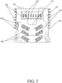
- FIG. 1 is a schematic structural view of a TF card connector which is capable of installing a Nano-SIM card according to one embodiment of the present invention.
- the TF card connector which is capable of installing a Nano-SIM card comprises a terminal retaining base 107, a first card slot (shown in FIG.
- a second card slot (shown in FIG. 3 ) is disposed on the terminal retaining base 107 and adapted to a Nano-SIM card, and a plurality of second conducting terminals 109 disposed on the terminal retaining base 107 wherein a plurality of first ends 106 of the second conducting terminals 109 are disposed in the second card slot for connecting to the Nano-SIM card and a plurality of second ends 104 of the second conducting terminals 109 are disposed in one side of the terminal retaining base 107 for connecting to a main board of the mobile phone.
- the TF card connector is improved by arranging a Nano-SIM card connector in the TF card connector so that the functions are increased for the TF card connector.
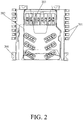
- FIG. 2 is a schematic assembly view of assembling a TF card in the TF card connector which is capable of installing a Nano-SIM card according to one embodiment of the present invention.
- the TF card connector which is capable of installing a Nano-SIM card is disposed on the main board of the mobile phone.
- a plurality of embossment structures 101 are disposed on the terminal retaining base 107 of the TF card connector which is capable of installing a Nano-SIM card.
- the embossment structures 101, the second ends of the first conducting terminals 108 and second ends of the second conducting terminals 109 are connected to the main board of the mobile phone by way of the plastic body 201.
- the TF card 202 After the TF card 202 is arranged in the TF card connector which is capable of installing a Nano-SIM card, the TF card triggers the TF card identification switch 203 disposed on the terminal retaining base 107 for closing the TF card identification switch 203. After the TF card identification switch 203 is in the closed status, a circuit disposed in the mobile phone is switched on for generating an interrupted signal to allow the mobile phone to identify the TF card while the mobile phone receives the interrupted signal.
- a pushing structure is disposed on the TF card connector which is capable of installing a Nano-SIM card wherein the pushing structure is an empty slot arranged in the TF card connector which is capable of installing a Nano-SIM card such that the user is capable of contacting the TF card by way of the empty slot to eject the TF card.
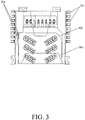
- FIG. 3 is a schematic assembly view of assembling a Nano-SIM card in the TF card connector which is capable of installing a Nano-SIM card according to one embodiment of the present invention.
- the Nano-SIM card 302 is arranged in the TF card connector which is capable of installing a Nano-SIM card
- the Nano-SIM card triggers the Nano-SIM card identification switch 301 disposed on the terminal retaining base 107 for closing the Nano-SIM card identification switch 301.
- a circuit disposed in the mobile phone is switched on for generating an interrupted signal to allow the mobile phone to identify the Nano-SIM card while the mobile phone receives the interrupted signal.
- an extracting structure 303 is disposed in the TF card connector to conveniently insert the Nano-SIM card into the TF card connector or extract the Nano-SIM card from the TF card connector.
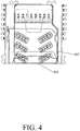
- FIG. 4 is a schematic assembly view of assembling the TF card and the Nano-SIM card in the TF card connector which is capable of installing a Nano-SIM card according to one embodiment of the present invention.
- the TF card and the Nano-SIM card are arranged in the TF card connector which is capable of installing a Nano-SIM card.
- the second card slot is opened and disposed on the bottom surface of the first card slot.
- the two sides 402, 401 of the second card slot and the first card slot are overlapped. This maintains the structure of TF card connector so that the Nano-SIM card connector is arranged in the TF card connector to save the space for the mobile phone.
- the second ends of the first conducting terminals and the second ends of the second conducting terminals are disposed respectively in the same side of the terminal retaining base.
- the installation position of the TF card connector which is capable of installing a Nano-SIM card is configured without restriction in order to arrange the TF card connector which is capable of installing a Nano-SIM card in the main board's edge of the mobile phone.
- the second ends of the first conducting terminals and the second ends of the second conducting terminals are disposed respectively in the different sides of the terminal retaining base.
- the connection strength between TF card connector which is capable of installing a Nano-SIM card and the mobile phone's main board is stronger for simplifying the difficulty of the circuit design of the main board in the mobile phone.
- Nano-SIM card is a new generation of SIM card in the mobile phone, which is smaller and thinner than the micro-SIM card.
- the Nano-SIM card has to support eight kinds of circuits but not to require how to arrange the eight contact electrical pads.
- the invention discloses a TF card connector which is capable of installing a Nano-SIM card and a mobile phone thereof.
- the TF card connector is improved by arranging a Nano-SIM card connector in the TF card connector so that the functions are increased for the TF card connector.
- the mobile phone have the function of installing an SIM card by arranging the TF card connector capable of installing the Nano-SIM card in the mobile phone to increase the novel functions for the mobile phone such that the Nano-SIM card is used simply and conveniently after the Nano-SIM card is installed.
Landscapes
- Engineering & Computer Science (AREA)
- Physics & Mathematics (AREA)
- General Physics & Mathematics (AREA)
- Theoretical Computer Science (AREA)
- Artificial Intelligence (AREA)
- Computer Vision & Pattern Recognition (AREA)
- Coupling Device And Connection With Printed Circuit (AREA)
- Telephone Set Structure (AREA)
Abstract
Description
- The present invention relates to a connector installed in the mobile phone, and more particularly to a TF card connector which is capable of installing a Nano-SIM card and a mobile phone thereof.
- Currently, almost all mobile phones can be installed with memory cards and a widely-used memory card is the TF card. However, conventionally, the TF card connector within the mobile phone is only for inserting TF card therein, which is too simple.
- Consequently, there is a need to solve the above problem and develop a new technique.
- Based on the aforementioned problems, one objective of the present invention is to provide a TF card and the Nano-SIM card in the TF card connector which is capable of installing a Nano-SIM card and a mobile phone thereof for increasing the functions of the TF card connector to allow the TF card connector to be installed by TF card and Nano-SIM card.
- For the above-mentioned objective, the present invention employs the following technical scheme.
- A TF card connector which is capable of installing a Nano-SIM card, comprises a terminal retaining base, a first card slot disposed on the terminal retaining base and adapted to a TF card, and a plurality of first conducting terminals disposed on the terminal retaining base wherein a plurality of first ends of the first conducting terminals are disposed in the first card slot for connecting to the TF card and a plurality of second ends of the first conducting terminals are disposed in one side of the terminal retaining base for connecting to a main board of the mobile phone, wherein the TF card connector further comprises:
- a second card slot disposed on the terminal retaining base and adapted to a Nano-SIM card, and a plurality of second conducting terminals disposed on the terminal retaining base wherein a plurality of first ends of the second conducting terminals are disposed in the second card slot for connecting to the Nano-SIM card and a plurality of second ends of the second conducting terminals are disposed in one side of the terminal retaining base for connecting to the main board of the mobile phone;
a pushing structure disposed on the terminal retaining base; and
a plurality of embossment structures disposed on the terminal retaining base. - The TF card connector which is capable of installing the Nano-SIM card further comprises the Nano-SIM card identification switch disposed on the terminal retaining base for closing the Nano-SIM card identification switch when the Nano-SIM card is inserted.
- The TF card connector which is capable of installing the Nano-SIM card further comprises a TF card identification switch disposed on the terminal retaining base for closing the TF card identification switch when the TF card is inserted.
- In the TF card connector which is capable of installing the Nano-SIM card, the second ends of the first conducting terminals and the second ends of the second conducting terminals are disposed respectively in the same side of the terminal retaining base.
- In the TF card connector which is capable of installing the Nano-SIM card, the second ends of the first conducting terminals and the second ends of the second conducting terminals are disposed respectively in the different sides of the terminal retaining base.
- In the TF card connector which is capable of installing the Nano-SIM card, the second card slot is opened and disposed on a bottom surface of the first card slot.
- In the TF card connector which is capable of installing the Nano-SIM card, two sides of the second card slot and the first card slot are overlapped and eight second conducting terminals are disposed on the TF card connector which is capable of installing the Nano-SIM card.
- For the above-mentioned objective, the present invention employs the following technical scheme.
- A TF card connector which is capable of installing a Nano-SIM card, comprises a terminal retaining base, a first card slot disposed on the terminal retaining base and adapted to a TF card, and a plurality of first conducting terminals disposed on the terminal retaining base wherein a plurality of first ends of the first conducting terminals are disposed in the first card slot for connecting to the TF card and a plurality of second ends of the first conducting terminals are disposed in one side of the terminal retaining base for connecting to a main board of the mobile phone, wherein the TF card connector further comprises:
- a second card slot disposed on the terminal retaining base and adapted to a Nano-SIM card, and a plurality of second conducting terminals disposed on the terminal retaining base wherein a plurality of first ends of the second conducting terminals are disposed in the second card slot for connecting to the Nano-SIM card and a plurality of second ends of the second conducting terminals are disposed in one side of the terminal retaining base for connecting to the main board of the mobile phone.
- The TF card connector which is capable of installing the Nano-SIM card further comprises the Nano-SIM card identification switch disposed on the terminal retaining base for closing the Nano-SIM card identification switch when the Nano-SIM card is inserted.
- The TF card connector which is capable of installing the Nano-SIM card further comprises a TF card identification switch disposed on the terminal retaining base for closing the TF card identification switch when the TF card is inserted.
- The TF card connector which is capable of installing the Nano-SIM card further comprises a pushing structure disposed on the terminal retaining base.
- In the TF card connector which is capable of installing the Nano-SIM card, the second ends of the first conducting terminals and the second ends of the second conducting terminals are disposed respectively in the same side of the terminal retaining base.
- In the TF card connector which is capable of installing the Nano-SIM card, the second ends of the first conducting terminals and the second ends of the second conducting terminals are disposed respectively in the different sides of the terminal retaining base.
- In the TF card connector which is capable of installing the Nano-SIM card, the second card slot is opened and disposed on a bottom surface of the first card slot.
- In the TF card connector which is capable of installing the Nano-SIM card, two sides of the second card slot and the first card slot are overlapped and eight second conducting terminals are disposed on the TF card connector which is capable of installing the Nano-SIM card.
- The TF card connector which is capable of installing the Nano-SIM card further comprises a plurality of embossment structures disposed on the terminal retaining base.
- A mobile phone comprises the TF card connector which is capable of installing the Nano-SIM card described in the above-mentioned descriptions.
- The invention discloses a TF card connector which is capable of installing a Nano-SIM card and a mobile phone thereof. The TF card connector is improved by arranging a Nano-SIM card connector in the TF card connector so that the functions are increased for the TF card connector. The mobile phone have the function of installing an SIM card by arranging the TF card connector capable of installing the Nano-SIM card in the mobile phone to increase the novel functions for the mobile phone such that the Nano-SIM card is used simply and conveniently after the Nano-SIM card is installed.
-
-
FIG. 1 is a schematic structural view of a TF card connector which is capable of installing a Nano-SIM card according to one embodiment of the present invention; -
FIG. 2 is a schematic assembly view of assembling a TF card in the TF card connector which is capable of installing a Nano-SIM card according to one embodiment of the present invention; -
FIG. 3 is a schematic assembly view of assembling a Nano-SIM card in the TF card connector which is capable of installing a Nano-SIM card according to one embodiment of the present invention; and -
FIG. 4 is a schematic assembly view of assembling the TF card and the Nano-SIM card in the TF card connector which is capable of installing a Nano-SIM card according to one embodiment of the present invention. - The present invention provides a TF card connector which is capable of installing a Nano-SIM card and a mobile phone thereof. The foregoing aspects and many of the attendant advantages of this invention will become more readily appreciated as the same becomes better understood by reference to the following detailed description, when taken in conjunction with the accompanying drawings. It should be noted that the described embodiments are merely used to explain the present invention rather than limiting of the present invention.
- Refer to
FIG. 1 , which is a schematic structural view of a TF card connector which is capable of installing a Nano-SIM card according to one embodiment of the present invention. As shown inFIG. 1 , the TF card connector which is capable of installing a Nano-SIM card comprises aterminal retaining base 107, a first card slot (shown inFIG. 2 ) disposed on theterminal retaining base 107 and adapted to a TF card, and a plurality of first conductingterminals 108 disposed on theterminal retaining base 107 wherein a plurality offirst ends 102 of the first conductingterminals 108 are disposed in the first card slot for connecting to the TF card and a plurality ofsecond ends 105 of the first conductingterminals 108 are disposed in one side of theterminal retaining base 107 for connecting to a main board of the mobile phone. - A second card slot (shown in
FIG. 3 ) is disposed on theterminal retaining base 107 and adapted to a Nano-SIM card, and a plurality ofsecond conducting terminals 109 disposed on theterminal retaining base 107 wherein a plurality offirst ends 106 of thesecond conducting terminals 109 are disposed in the second card slot for connecting to the Nano-SIM card and a plurality ofsecond ends 104 of the second conductingterminals 109 are disposed in one side of theterminal retaining base 107 for connecting to a main board of the mobile phone. - As the aforementioned TF card connector which is capable of installing a Nano-SIM card, the TF card connector is improved by arranging a Nano-SIM card connector in the TF card connector so that the functions are increased for the TF card connector.
- Refer to
FIG. 2 , which is a schematic assembly view of assembling a TF card in the TF card connector which is capable of installing a Nano-SIM card according to one embodiment of the present invention. As shown inFIG. 2 , the TF card connector which is capable of installing a Nano-SIM card is disposed on the main board of the mobile phone. A plurality of embossment structures 101 (as shown inFIG. 1 ) are disposed on theterminal retaining base 107 of the TF card connector which is capable of installing a Nano-SIM card. Theembossment structures 101, the second ends of the first conductingterminals 108 and second ends of the second conductingterminals 109 are connected to the main board of the mobile phone by way of theplastic body 201. After theTF card 202 is arranged in the TF card connector which is capable of installing a Nano-SIM card, the TF card triggers the TFcard identification switch 203 disposed on theterminal retaining base 107 for closing the TFcard identification switch 203. After the TFcard identification switch 203 is in the closed status, a circuit disposed in the mobile phone is switched on for generating an interrupted signal to allow the mobile phone to identify the TF card while the mobile phone receives the interrupted signal. - Continuously refer to
FIG. 1 . In order to conveniently extract the TF card from the TF card connector, a pushing structure is disposed on the TF card connector which is capable of installing a Nano-SIM card wherein the pushing structure is an empty slot arranged in the TF card connector which is capable of installing a Nano-SIM card such that the user is capable of contacting the TF card by way of the empty slot to eject the TF card. - Refer to
FIG. 3 , which is a schematic assembly view of assembling a Nano-SIM card in the TF card connector which is capable of installing a Nano-SIM card according to one embodiment of the present invention. As shown inFIG. 3 , after the Nano-SIM card 302 is arranged in the TF card connector which is capable of installing a Nano-SIM card, the Nano-SIM card triggers the Nano-SIMcard identification switch 301 disposed on theterminal retaining base 107 for closing the Nano-SIMcard identification switch 301. After the Nano-SIMcard identification switch 301 is in the closed status, a circuit disposed in the mobile phone is switched on for generating an interrupted signal to allow the mobile phone to identify the Nano-SIM card while the mobile phone receives the interrupted signal. Similar to the above-mentioned pushing structure, an extractingstructure 303 is disposed in the TF card connector to conveniently insert the Nano-SIM card into the TF card connector or extract the Nano-SIM card from the TF card connector. - Refer to
FIG. 4 , which is a schematic assembly view of assembling the TF card and the Nano-SIM card in the TF card connector which is capable of installing a Nano-SIM card according to one embodiment of the present invention. As shown inFIG. 4 , the TF card and the Nano-SIM card are arranged in the TF card connector which is capable of installing a Nano-SIM card. The second card slot is opened and disposed on the bottom surface of the first card slot. The twosides - In one preferred embodiment of the TF card connector which is capable of installing a Nano-SIM card, the second ends of the first conducting terminals and the second ends of the second conducting terminals are disposed respectively in the same side of the terminal retaining base. By arranging the second ends of the first conducting terminals and the second ends of the second conducting terminals in the same side of the terminal retaining base, the installation position of the TF card connector which is capable of installing a Nano-SIM card is configured without restriction in order to arrange the TF card connector which is capable of installing a Nano-SIM card in the main board's edge of the mobile phone.
- In one preferred embodiment of the TF card connector which is capable of installing a Nano-SIM card, the second ends of the first conducting terminals and the second ends of the second conducting terminals are disposed respectively in the different sides of the terminal retaining base. By arranging the second ends of the first conducting terminals and the second ends of the second conducting terminals in the different sides of the terminal retaining base, the connection strength between TF card connector which is capable of installing a Nano-SIM card and the mobile phone's main board is stronger for simplifying the difficulty of the circuit design of the main board in the mobile phone.
- In one preferred embodiment of the TF card connector which is capable of installing a Nano-SIM card, there are eight second conducting terminals. Nano-SIM card is a new generation of SIM card in the mobile phone, which is smaller and thinner than the micro-SIM card. Based on the ETSI standard, the Nano-SIM card has to support eight kinds of circuits but not to require how to arrange the eight contact electrical pads. According to the ETSI standard, the eight second conducting terminals to allow the TF card connector which is capable of installing a Nano-SIM card to make them much more integrated with the world in order to enter the international market.
- According to the above-mentioned descriptions, the invention discloses a TF card connector which is capable of installing a Nano-SIM card and a mobile phone thereof. The TF card connector is improved by arranging a Nano-SIM card connector in the TF card connector so that the functions are increased for the TF card connector. The mobile phone have the function of installing an SIM card by arranging the TF card connector capable of installing the Nano-SIM card in the mobile phone to increase the novel functions for the mobile phone such that the Nano-SIM card is used simply and conveniently after the Nano-SIM card is installed.
- As is understood by a person skilled in the art, the foregoing preferred embodiments of the present invention are illustrative rather than limiting of the present invention. It is intended that they cover various modifications and similar arrangements be included within the spirit and scope of the present invention, the scope of which should be accorded the broadest interpretation so as to encompass all such modifications and similar structures.
Claims (17)
- A TF card connector which is capable of installing a Nano-SIM card, comprising a terminal retaining base, a first card slot disposed on the terminal retaining base and adapted to a TF card, and a plurality of first conducting terminals disposed on the terminal retaining base wherein a plurality of first ends of the first conducting terminals are disposed in the first card slot for connecting to the TF card and a plurality of second ends of the first conducting terminals are disposed in one side of the terminal retaining base for connecting to a main board of the mobile phone, wherein the TF card connector further comprises:a second card slot disposed on the terminal retaining base and adapted to a Nano-SIM card, and a plurality of second conducting terminals disposed on the terminal retaining base wherein a plurality of first ends of the second conducting terminals are disposed in the second card slot for connecting to the Nano-SIM card and a plurality of second ends of the second conducting terminals are disposed in one side of the terminal retaining base for connecting to the main board of the mobile phone;a pushing structure disposed on the terminal retaining base; anda plurality of embossment structures disposed on the terminal retaining base.
- The TF card connector which is capable of installing the Nano-SIM card of claim 1, further comprising the Nano-SIM card identification switch disposed on the terminal retaining base for closing the Nano-SIM card identification switch when the Nano-SIM card is inserted.
- The TF card connector which is capable of installing the Nano-SIM card of claim 1, further comprising a TF card identification switch disposed on the terminal retaining base for closing the TF card identification switch when the TF card is inserted.
- The TF card connector which is capable of installing the Nano-SIM card of claim 1, wherein the second ends of the first conducting terminals and the second ends of the second conducting terminals are disposed respectively in the same side of the terminal retaining base.
- The TF card connector which is capable of installing the Nano-SIM card of claim 1, wherein the second ends of the first conducting terminals and the second ends of the second conducting terminals are disposed respectively in the different sides of the terminal retaining base.
- The TF card connector which is capable of installing the Nano-SIM card of claim 1, wherein the second card slot is opened and disposed on a bottom surface of the first card slot.
- The TF card connector which is capable of installing the Nano-SIM card of claim 1, wherein two sides of the second card slot and the first card slot are overlapped and eight second conducting terminals are disposed on the TF card connector which is capable of installing the Nano-SIM card.
- A TF card connector which is capable of installing a Nano-SIM card, comprising a terminal retaining base, a first card slot disposed on the terminal retaining base and adapted to a TF card, and a plurality of first conducting terminals disposed on the terminal retaining base wherein a plurality of first ends of the first conducting terminals are disposed in the first card slot for connecting to the TF card and a plurality of second ends of the first conducting terminals are disposed in one side of the terminal retaining base for connecting to a main board of the mobile phone, wherein the TF card connector further comprises:a second card slot disposed on the terminal retaining base and adapted to a Nano-SIM card, and a plurality of second conducting terminals disposed on the terminal retaining base wherein a plurality of first ends of the second conducting terminals are disposed in the second card slot for connecting to the Nano-SIM card and a plurality of second ends of the second conducting terminals are disposed in one side of the terminal retaining base for connecting to the main board of the mobile phone.
- The TF card connector which is capable of installing the Nano-SIM card of claim 8, further comprising the Nano-SIM card identification switch disposed on the terminal retaining base for closing the Nano-SIM card identification switch when the Nano-SIM card is inserted.
- The TF card connector which is capable of installing the Nano-SIM card of claim 8, further comprising a TF card identification switch disposed on the terminal retaining base for closing the TF card identification switch when the TF card is inserted.
- The TF card connector which is capable of installing the Nano-SIM card of claim 8, further comprising a pushing structure disposed on the terminal retaining base.
- The TF card connector which is capable of installing the Nano-SIM card of claim 8, wherein the second ends of the first conducting terminals and the second ends of the second conducting terminals are disposed respectively in the same side of the terminal retaining base.
- The TF card connector which is capable of installing the Nano-SIM card of claim 8, wherein the second ends of the first conducting terminals and the second ends of the second conducting terminals are disposed respectively in the different sides of the terminal retaining base.
- The TF card connector which is capable of installing the Nano-SIM card of claim 8, wherein the second card slot is opened and disposed on a bottom surface of the first card slot.
- The TF card connector which is capable of installing the Nano-SIM card of claim 8, wherein two sides of the second card slot and the first card slot are overlapped and eight second conducting terminals are disposed on the TF card connector which is capable of installing the Nano-SIM card.
- The TF card connector which is capable of installing the Nano-SIM card of claim 8, further comprising a plurality of embossment structures disposed on the terminal retaining base.
- A mobile phone, comprising the TF card connector which is capable of installing the Nano-SIM card described in any one of claims 8 to 16.
Applications Claiming Priority (2)
| Application Number | Priority Date | Filing Date | Title |
|---|---|---|---|
| CN201410354980.5A CN104124587B (en) | 2014-07-24 | 2014-07-24 | The TF card connectors and mobile phone of Nano SIM cards can be installed |
| PCT/CN2015/072532 WO2016011807A1 (en) | 2014-07-24 | 2015-02-09 | Tf card connector capable of installing nano-sim card, and mobile phone |
Publications (3)
| Publication Number | Publication Date |
|---|---|
| EP3174164A1 true EP3174164A1 (en) | 2017-05-31 |
| EP3174164A4 EP3174164A4 (en) | 2018-04-11 |
| EP3174164B1 EP3174164B1 (en) | 2020-10-14 |
Family
ID=51769908
Family Applications (1)
| Application Number | Title | Priority Date | Filing Date |
|---|---|---|---|
| EP15747350.5A Active EP3174164B1 (en) | 2014-07-24 | 2015-02-09 | Tf card connector capable of installing nano-sim card, and mobile phone |
Country Status (4)
| Country | Link |
|---|---|
| US (1) | US9728921B2 (en) |
| EP (1) | EP3174164B1 (en) |
| CN (1) | CN104124587B (en) |
| WO (1) | WO2016011807A1 (en) |
Families Citing this family (12)
| Publication number | Priority date | Publication date | Assignee | Title |
|---|---|---|---|---|
| CN104124587B (en) | 2014-07-24 | 2017-10-24 | 惠州Tcl移动通信有限公司 | The TF card connectors and mobile phone of Nano SIM cards can be installed |
| JP1552812S (en) * | 2015-11-03 | 2016-06-27 | ||
| JP1553611S (en) * | 2015-11-03 | 2016-07-11 | ||
| JP1553879S (en) * | 2015-11-03 | 2016-07-11 | ||
| JP1552814S (en) * | 2015-11-04 | 2016-06-27 | ||
| JP1552813S (en) * | 2015-11-04 | 2016-06-27 | ||
| JP1552815S (en) * | 2015-11-06 | 2016-06-27 | ||
| TWI601341B (en) * | 2015-11-13 | 2017-10-01 | Molex Llc | Electronic card connector |
| CN118607569A (en) * | 2018-02-01 | 2024-09-06 | 华为技术有限公司 | Memory Cards and Terminals |
| KR102822688B1 (en) * | 2019-12-18 | 2025-06-23 | 삼성전자주식회사 | Ufs memory card |
| JP1680769S (en) * | 2020-05-14 | 2021-03-08 | ||
| TWM602292U (en) * | 2020-07-03 | 2020-10-01 | 正崴精密工業股份有限公司 | Sim card connector |
Family Cites Families (21)
| Publication number | Priority date | Publication date | Assignee | Title |
|---|---|---|---|---|
| US20040208572A1 (en) | 2001-12-27 | 2004-10-21 | Koninklijke Philips Electronics N.W. | WDM optical transmission system with passive hub |
| JP4324566B2 (en) * | 2005-01-21 | 2009-09-02 | ホシデン株式会社 | Memory card adapter |
| US20090019224A1 (en) * | 2005-02-02 | 2009-01-15 | Pocrass Alan L | Data Storage and Transfer Device and Method |
| US20060216999A1 (en) * | 2005-03-28 | 2006-09-28 | Wem Technology Inc. | 5-In-1 connector for memory cards |
| TWM297564U (en) * | 2006-03-24 | 2006-09-11 | Advanced Connectek Inc | Connector of memory-card card |
| JP2008218045A (en) * | 2007-02-28 | 2008-09-18 | Fujitsu Component Ltd | Card connector |
| CN201247885Y (en) * | 2008-07-25 | 2009-05-27 | 富港电子(东莞)有限公司 | Card connector |
| CN201594678U (en) | 2010-02-05 | 2010-09-29 | 昆山杰顺通精密组件有限公司 | Multi-card connector |
| CN201766180U (en) * | 2010-04-12 | 2011-03-16 | 段志刚 | Three-in-one card socket electronic connector of mobile phone SIM card and memory card |
| CN103311721B (en) * | 2012-03-16 | 2015-10-21 | 莫仕连接器(成都)有限公司 | Double SIM card pallet, connector modules and electric connector |
| US8747162B2 (en) * | 2012-03-29 | 2014-06-10 | Sandisk Technologies Inc. | Host device with memory card slot having a card gripping-extracting recess |
| KR101327302B1 (en) | 2012-04-30 | 2013-11-20 | 한국몰렉스 주식회사 | Dual memory card socket and manufacturing method thereof |
| US20140099805A1 (en) * | 2012-10-10 | 2014-04-10 | Motorola Mobility Llc | Electronic connector capable of accepting a single subscriber identity mopdule or a memory card |
| CN202840165U (en) * | 2012-10-15 | 2013-03-27 | 中兴通讯股份有限公司 | Subscriber identity module (SIM) card compatible device and associated terminal |
| CN202977848U (en) * | 2012-11-28 | 2013-06-05 | 深圳市益晟康科技有限公司 | TF card/SIM card double-layer connector |
| CN202977785U (en) * | 2012-12-12 | 2013-06-05 | 莫仕连接器(成都)有限公司 | Electric connector |
| KR102035776B1 (en) * | 2013-01-17 | 2019-10-23 | 삼성전자 주식회사 | SIM-card Socket and Electronic Device including the same |
| KR200473528Y1 (en) | 2013-02-25 | 2014-07-09 | 주식회사 제이앤티씨 | A socket for SIM Card |
| CN203340135U (en) * | 2013-06-26 | 2013-12-11 | Tcl通讯(宁波)有限公司 | Integrated interface structure and handset |
| CN103367951B (en) * | 2013-06-28 | 2016-03-02 | 华为终端有限公司 | Digital card holder |
| CN104124587B (en) | 2014-07-24 | 2017-10-24 | 惠州Tcl移动通信有限公司 | The TF card connectors and mobile phone of Nano SIM cards can be installed |
-
2014
- 2014-07-24 CN CN201410354980.5A patent/CN104124587B/en active Active
-
2015
- 2015-02-09 EP EP15747350.5A patent/EP3174164B1/en active Active
- 2015-02-09 US US14/890,504 patent/US9728921B2/en active Active
- 2015-02-09 WO PCT/CN2015/072532 patent/WO2016011807A1/en not_active Ceased
Also Published As
| Publication number | Publication date |
|---|---|
| WO2016011807A1 (en) | 2016-01-28 |
| US20170125932A1 (en) | 2017-05-04 |
| US9728921B2 (en) | 2017-08-08 |
| CN104124587B (en) | 2017-10-24 |
| CN104124587A (en) | 2014-10-29 |
| EP3174164A4 (en) | 2018-04-11 |
| EP3174164B1 (en) | 2020-10-14 |
Similar Documents
| Publication | Publication Date | Title |
|---|---|---|
| US9728921B2 (en) | TF card connector which is capable of installing Nano-SIM card and mobile phone thereof | |
| JP5867656B2 (en) | Device for fixing digital memory card | |
| CN104241893B (en) | Card connectors and electronic devices | |
| US9985674B2 (en) | SIM card connector and mobile terminal having the SIM card connector | |
| KR20080106728A (en) | Socket with memory card and SIM card with integrated sensing switch | |
| EP2757702A1 (en) | Sim card socket and terminal device including the same | |
| KR20130056666A (en) | Mounting socket for mobile phone | |
| EP3128623A1 (en) | Sim card cassette and mobile terminal provided with sim card cassette | |
| CN105449437B (en) | Plug-in device and terminal | |
| CN104319520B (en) | Connector and terminal equipment with the same | |
| US10305231B2 (en) | Card connector and manufacturing method thereof | |
| CN104659600B (en) | A kind of sim card connector | |
| CN203982355U (en) | Digital card stationary installation and electronic equipment | |
| KR101468952B1 (en) | Easily separable card tray | |
| CN204597099U (en) | A deck and electronic equipment | |
| CN204481190U (en) | A new type of SIM card socket connector | |
| CN104577515B (en) | Card seat provided with sensing mechanism and resetting mechanism | |
| CN202817376U (en) | SIM card connector and mobile communication device with the same | |
| CN205264914U (en) | Plug -in card device and terminal | |
| KR20140046183A (en) | Slim type micro sim connector | |
| CN204464531U (en) | Connector and mobile terminal with same | |
| US8454386B1 (en) | Eletronic device having a tray for placing digital card | |
| CN204089893U (en) | A kind of mobile phone card seat with buckle | |
| CN204271297U (en) | A tray-type SIM card holder | |
| CN204103183U (en) | Card connector and mobile terminal with the card connector |
Legal Events
| Date | Code | Title | Description |
|---|---|---|---|
| STAA | Information on the status of an ep patent application or granted ep patent |
Free format text: STATUS: THE INTERNATIONAL PUBLICATION HAS BEEN MADE |
|
| PUAI | Public reference made under article 153(3) epc to a published international application that has entered the european phase |
Free format text: ORIGINAL CODE: 0009012 |
|
| STAA | Information on the status of an ep patent application or granted ep patent |
Free format text: STATUS: REQUEST FOR EXAMINATION WAS MADE |
|
| 17P | Request for examination filed |
Effective date: 20170223 |
|
| AK | Designated contracting states |
Kind code of ref document: A1 Designated state(s): AL AT BE BG CH CY CZ DE DK EE ES FI FR GB GR HR HU IE IS IT LI LT LU LV MC MK MT NL NO PL PT RO RS SE SI SK SM TR |
|
| AX | Request for extension of the european patent |
Extension state: BA ME |
|
| DAX | Request for extension of the european patent (deleted) | ||
| A4 | Supplementary search report drawn up and despatched |
Effective date: 20180314 |
|
| RIC1 | Information provided on ipc code assigned before grant |
Ipc: H01R 27/02 20060101AFI20180307BHEP Ipc: G06K 7/00 20060101ALI20180307BHEP |
|
| STAA | Information on the status of an ep patent application or granted ep patent |
Free format text: STATUS: EXAMINATION IS IN PROGRESS |
|
| 17Q | First examination report despatched |
Effective date: 20190724 |
|
| REG | Reference to a national code |
Ref country code: DE Ref legal event code: R079 Ref document number: 602015060447 Country of ref document: DE Free format text: PREVIOUS MAIN CLASS: H01R0013514000 Ipc: G06K0013080000 |
|
| GRAP | Despatch of communication of intention to grant a patent |
Free format text: ORIGINAL CODE: EPIDOSNIGR1 |
|
| RIC1 | Information provided on ipc code assigned before grant |
Ipc: G06K 13/08 20060101AFI20200428BHEP Ipc: H01R 27/02 20060101ALI20200428BHEP Ipc: G06K 7/00 20060101ALI20200428BHEP |
|
| STAA | Information on the status of an ep patent application or granted ep patent |
Free format text: STATUS: GRANT OF PATENT IS INTENDED |
|
| INTG | Intention to grant announced |
Effective date: 20200604 |
|
| GRAS | Grant fee paid |
Free format text: ORIGINAL CODE: EPIDOSNIGR3 |
|
| GRAA | (expected) grant |
Free format text: ORIGINAL CODE: 0009210 |
|
| STAA | Information on the status of an ep patent application or granted ep patent |
Free format text: STATUS: THE PATENT HAS BEEN GRANTED |
|
| AK | Designated contracting states |
Kind code of ref document: B1 Designated state(s): AL AT BE BG CH CY CZ DE DK EE ES FI FR GB GR HR HU IE IS IT LI LT LU LV MC MK MT NL NO PL PT RO RS SE SI SK SM TR |
|
| REG | Reference to a national code |
Ref country code: GB Ref legal event code: FG4D |
|
| REG | Reference to a national code |
Ref country code: AT Ref legal event code: REF Ref document number: 1324300 Country of ref document: AT Kind code of ref document: T Effective date: 20201015 Ref country code: CH Ref legal event code: EP |
|
| REG | Reference to a national code |
Ref country code: DE Ref legal event code: R096 Ref document number: 602015060447 Country of ref document: DE |
|
| REG | Reference to a national code |
Ref country code: IE Ref legal event code: FG4D |
|
| REG | Reference to a national code |
Ref country code: AT Ref legal event code: MK05 Ref document number: 1324300 Country of ref document: AT Kind code of ref document: T Effective date: 20201014 |
|
| REG | Reference to a national code |
Ref country code: NL Ref legal event code: MP Effective date: 20201014 |
|
| PG25 | Lapsed in a contracting state [announced via postgrant information from national office to epo] |
Ref country code: PT Free format text: LAPSE BECAUSE OF FAILURE TO SUBMIT A TRANSLATION OF THE DESCRIPTION OR TO PAY THE FEE WITHIN THE PRESCRIBED TIME-LIMIT Effective date: 20210215 Ref country code: RS Free format text: LAPSE BECAUSE OF FAILURE TO SUBMIT A TRANSLATION OF THE DESCRIPTION OR TO PAY THE FEE WITHIN THE PRESCRIBED TIME-LIMIT Effective date: 20201014 Ref country code: FI Free format text: LAPSE BECAUSE OF FAILURE TO SUBMIT A TRANSLATION OF THE DESCRIPTION OR TO PAY THE FEE WITHIN THE PRESCRIBED TIME-LIMIT Effective date: 20201014 Ref country code: NL Free format text: LAPSE BECAUSE OF FAILURE TO SUBMIT A TRANSLATION OF THE DESCRIPTION OR TO PAY THE FEE WITHIN THE PRESCRIBED TIME-LIMIT Effective date: 20201014 Ref country code: NO Free format text: LAPSE BECAUSE OF FAILURE TO SUBMIT A TRANSLATION OF THE DESCRIPTION OR TO PAY THE FEE WITHIN THE PRESCRIBED TIME-LIMIT Effective date: 20210114 Ref country code: GR Free format text: LAPSE BECAUSE OF FAILURE TO SUBMIT A TRANSLATION OF THE DESCRIPTION OR TO PAY THE FEE WITHIN THE PRESCRIBED TIME-LIMIT Effective date: 20210115 |
|
| REG | Reference to a national code |
Ref country code: LT Ref legal event code: MG4D |
|
| PG25 | Lapsed in a contracting state [announced via postgrant information from national office to epo] |
Ref country code: SE Free format text: LAPSE BECAUSE OF FAILURE TO SUBMIT A TRANSLATION OF THE DESCRIPTION OR TO PAY THE FEE WITHIN THE PRESCRIBED TIME-LIMIT Effective date: 20201014 Ref country code: PL Free format text: LAPSE BECAUSE OF FAILURE TO SUBMIT A TRANSLATION OF THE DESCRIPTION OR TO PAY THE FEE WITHIN THE PRESCRIBED TIME-LIMIT Effective date: 20201014 Ref country code: IS Free format text: LAPSE BECAUSE OF FAILURE TO SUBMIT A TRANSLATION OF THE DESCRIPTION OR TO PAY THE FEE WITHIN THE PRESCRIBED TIME-LIMIT Effective date: 20210214 Ref country code: LV Free format text: LAPSE BECAUSE OF FAILURE TO SUBMIT A TRANSLATION OF THE DESCRIPTION OR TO PAY THE FEE WITHIN THE PRESCRIBED TIME-LIMIT Effective date: 20201014 Ref country code: BG Free format text: LAPSE BECAUSE OF FAILURE TO SUBMIT A TRANSLATION OF THE DESCRIPTION OR TO PAY THE FEE WITHIN THE PRESCRIBED TIME-LIMIT Effective date: 20210114 Ref country code: ES Free format text: LAPSE BECAUSE OF FAILURE TO SUBMIT A TRANSLATION OF THE DESCRIPTION OR TO PAY THE FEE WITHIN THE PRESCRIBED TIME-LIMIT Effective date: 20201014 Ref country code: AT Free format text: LAPSE BECAUSE OF FAILURE TO SUBMIT A TRANSLATION OF THE DESCRIPTION OR TO PAY THE FEE WITHIN THE PRESCRIBED TIME-LIMIT Effective date: 20201014 |
|
| PG25 | Lapsed in a contracting state [announced via postgrant information from national office to epo] |
Ref country code: HR Free format text: LAPSE BECAUSE OF FAILURE TO SUBMIT A TRANSLATION OF THE DESCRIPTION OR TO PAY THE FEE WITHIN THE PRESCRIBED TIME-LIMIT Effective date: 20201014 |
|
| REG | Reference to a national code |
Ref country code: DE Ref legal event code: R097 Ref document number: 602015060447 Country of ref document: DE |
|
| PG25 | Lapsed in a contracting state [announced via postgrant information from national office to epo] |
Ref country code: SM Free format text: LAPSE BECAUSE OF FAILURE TO SUBMIT A TRANSLATION OF THE DESCRIPTION OR TO PAY THE FEE WITHIN THE PRESCRIBED TIME-LIMIT Effective date: 20201014 Ref country code: EE Free format text: LAPSE BECAUSE OF FAILURE TO SUBMIT A TRANSLATION OF THE DESCRIPTION OR TO PAY THE FEE WITHIN THE PRESCRIBED TIME-LIMIT Effective date: 20201014 Ref country code: CZ Free format text: LAPSE BECAUSE OF FAILURE TO SUBMIT A TRANSLATION OF THE DESCRIPTION OR TO PAY THE FEE WITHIN THE PRESCRIBED TIME-LIMIT Effective date: 20201014 Ref country code: RO Free format text: LAPSE BECAUSE OF FAILURE TO SUBMIT A TRANSLATION OF THE DESCRIPTION OR TO PAY THE FEE WITHIN THE PRESCRIBED TIME-LIMIT Effective date: 20201014 Ref country code: SK Free format text: LAPSE BECAUSE OF FAILURE TO SUBMIT A TRANSLATION OF THE DESCRIPTION OR TO PAY THE FEE WITHIN THE PRESCRIBED TIME-LIMIT Effective date: 20201014 Ref country code: LT Free format text: LAPSE BECAUSE OF FAILURE TO SUBMIT A TRANSLATION OF THE DESCRIPTION OR TO PAY THE FEE WITHIN THE PRESCRIBED TIME-LIMIT Effective date: 20201014 |
|
| PLBE | No opposition filed within time limit |
Free format text: ORIGINAL CODE: 0009261 |
|
| STAA | Information on the status of an ep patent application or granted ep patent |
Free format text: STATUS: NO OPPOSITION FILED WITHIN TIME LIMIT |
|
| PG25 | Lapsed in a contracting state [announced via postgrant information from national office to epo] |
Ref country code: DK Free format text: LAPSE BECAUSE OF FAILURE TO SUBMIT A TRANSLATION OF THE DESCRIPTION OR TO PAY THE FEE WITHIN THE PRESCRIBED TIME-LIMIT Effective date: 20201014 |
|
| 26N | No opposition filed |
Effective date: 20210715 |
|
| PG25 | Lapsed in a contracting state [announced via postgrant information from national office to epo] |
Ref country code: MC Free format text: LAPSE BECAUSE OF FAILURE TO SUBMIT A TRANSLATION OF THE DESCRIPTION OR TO PAY THE FEE WITHIN THE PRESCRIBED TIME-LIMIT Effective date: 20201014 |
|
| REG | Reference to a national code |
Ref country code: BE Ref legal event code: MM Effective date: 20210228 |
|
| PG25 | Lapsed in a contracting state [announced via postgrant information from national office to epo] |
Ref country code: AL Free format text: LAPSE BECAUSE OF FAILURE TO SUBMIT A TRANSLATION OF THE DESCRIPTION OR TO PAY THE FEE WITHIN THE PRESCRIBED TIME-LIMIT Effective date: 20201014 Ref country code: CH Free format text: LAPSE BECAUSE OF NON-PAYMENT OF DUE FEES Effective date: 20210228 Ref country code: IT Free format text: LAPSE BECAUSE OF FAILURE TO SUBMIT A TRANSLATION OF THE DESCRIPTION OR TO PAY THE FEE WITHIN THE PRESCRIBED TIME-LIMIT Effective date: 20201014 Ref country code: LI Free format text: LAPSE BECAUSE OF NON-PAYMENT OF DUE FEES Effective date: 20210228 Ref country code: LU Free format text: LAPSE BECAUSE OF NON-PAYMENT OF DUE FEES Effective date: 20210209 |
|
| PG25 | Lapsed in a contracting state [announced via postgrant information from national office to epo] |
Ref country code: SI Free format text: LAPSE BECAUSE OF FAILURE TO SUBMIT A TRANSLATION OF THE DESCRIPTION OR TO PAY THE FEE WITHIN THE PRESCRIBED TIME-LIMIT Effective date: 20201014 |
|
| PG25 | Lapsed in a contracting state [announced via postgrant information from national office to epo] |
Ref country code: IE Free format text: LAPSE BECAUSE OF NON-PAYMENT OF DUE FEES Effective date: 20210209 |
|
| PG25 | Lapsed in a contracting state [announced via postgrant information from national office to epo] |
Ref country code: IS Free format text: LAPSE BECAUSE OF FAILURE TO SUBMIT A TRANSLATION OF THE DESCRIPTION OR TO PAY THE FEE WITHIN THE PRESCRIBED TIME-LIMIT Effective date: 20210214 |
|
| PG25 | Lapsed in a contracting state [announced via postgrant information from national office to epo] |
Ref country code: BE Free format text: LAPSE BECAUSE OF NON-PAYMENT OF DUE FEES Effective date: 20210228 |
|
| PG25 | Lapsed in a contracting state [announced via postgrant information from national office to epo] |
Ref country code: HU Free format text: LAPSE BECAUSE OF FAILURE TO SUBMIT A TRANSLATION OF THE DESCRIPTION OR TO PAY THE FEE WITHIN THE PRESCRIBED TIME-LIMIT; INVALID AB INITIO Effective date: 20150209 |
|
| PG25 | Lapsed in a contracting state [announced via postgrant information from national office to epo] |
Ref country code: CY Free format text: LAPSE BECAUSE OF FAILURE TO SUBMIT A TRANSLATION OF THE DESCRIPTION OR TO PAY THE FEE WITHIN THE PRESCRIBED TIME-LIMIT Effective date: 20201014 |
|
| P01 | Opt-out of the competence of the unified patent court (upc) registered |
Effective date: 20230530 |
|
| PG25 | Lapsed in a contracting state [announced via postgrant information from national office to epo] |
Ref country code: MK Free format text: LAPSE BECAUSE OF FAILURE TO SUBMIT A TRANSLATION OF THE DESCRIPTION OR TO PAY THE FEE WITHIN THE PRESCRIBED TIME-LIMIT Effective date: 20201014 |
|
| PG25 | Lapsed in a contracting state [announced via postgrant information from national office to epo] |
Ref country code: MT Free format text: LAPSE BECAUSE OF FAILURE TO SUBMIT A TRANSLATION OF THE DESCRIPTION OR TO PAY THE FEE WITHIN THE PRESCRIBED TIME-LIMIT Effective date: 20201014 |
|
| PG25 | Lapsed in a contracting state [announced via postgrant information from national office to epo] |
Ref country code: TR Free format text: LAPSE BECAUSE OF FAILURE TO SUBMIT A TRANSLATION OF THE DESCRIPTION OR TO PAY THE FEE WITHIN THE PRESCRIBED TIME-LIMIT Effective date: 20201014 |
|
| PGFP | Annual fee paid to national office [announced via postgrant information from national office to epo] |
Ref country code: GB Payment date: 20260219 Year of fee payment: 12 |
|
| PGFP | Annual fee paid to national office [announced via postgrant information from national office to epo] |
Ref country code: DE Payment date: 20260218 Year of fee payment: 12 |
|
| PGFP | Annual fee paid to national office [announced via postgrant information from national office to epo] |
Ref country code: FR Payment date: 20260218 Year of fee payment: 12 |