EP3174075A1 - Reactor - Google Patents
Reactor Download PDFInfo
- Publication number
- EP3174075A1 EP3174075A1 EP16020456.6A EP16020456A EP3174075A1 EP 3174075 A1 EP3174075 A1 EP 3174075A1 EP 16020456 A EP16020456 A EP 16020456A EP 3174075 A1 EP3174075 A1 EP 3174075A1
- Authority
- EP
- European Patent Office
- Prior art keywords
- coils
- annular groove
- groove portion
- outer peripheral
- peripheral walls
- Prior art date
- Legal status (The legal status is an assumption and is not a legal conclusion. Google has not performed a legal analysis and makes no representation as to the accuracy of the status listed.)
- Granted
Links
Images





Classifications
-
- H—ELECTRICITY
- H01—ELECTRIC ELEMENTS
- H01F—MAGNETS; INDUCTANCES; TRANSFORMERS; SELECTION OF MATERIALS FOR THEIR MAGNETIC PROPERTIES
- H01F27/00—Details of transformers or inductances, in general
- H01F27/02—Casings
-
- H—ELECTRICITY
- H01—ELECTRIC ELEMENTS
- H01F—MAGNETS; INDUCTANCES; TRANSFORMERS; SELECTION OF MATERIALS FOR THEIR MAGNETIC PROPERTIES
- H01F27/00—Details of transformers or inductances, in general
- H01F27/28—Coils; Windings; Conductive connections
- H01F27/30—Fastening or clamping coils, windings, or parts thereof together; Fastening or mounting coils or windings on core, casing, or other support
- H01F27/306—Fastening or mounting coils or windings on core, casing or other support
-
- H—ELECTRICITY
- H01—ELECTRIC ELEMENTS
- H01F—MAGNETS; INDUCTANCES; TRANSFORMERS; SELECTION OF MATERIALS FOR THEIR MAGNETIC PROPERTIES
- H01F37/00—Fixed inductances not covered by group H01F17/00
-
- H—ELECTRICITY
- H01—ELECTRIC ELEMENTS
- H01F—MAGNETS; INDUCTANCES; TRANSFORMERS; SELECTION OF MATERIALS FOR THEIR MAGNETIC PROPERTIES
- H01F27/00—Details of transformers or inductances, in general
- H01F27/24—Magnetic cores
-
- H—ELECTRICITY
- H01—ELECTRIC ELEMENTS
- H01F—MAGNETS; INDUCTANCES; TRANSFORMERS; SELECTION OF MATERIALS FOR THEIR MAGNETIC PROPERTIES
- H01F27/00—Details of transformers or inductances, in general
- H01F27/24—Magnetic cores
- H01F27/26—Fastening parts of the core together; Fastening or mounting the core on casing or support
- H01F27/263—Fastening parts of the core together
-
- H—ELECTRICITY
- H01—ELECTRIC ELEMENTS
- H01F—MAGNETS; INDUCTANCES; TRANSFORMERS; SELECTION OF MATERIALS FOR THEIR MAGNETIC PROPERTIES
- H01F27/00—Details of transformers or inductances, in general
- H01F27/28—Coils; Windings; Conductive connections
-
- H—ELECTRICITY
- H01—ELECTRIC ELEMENTS
- H01F—MAGNETS; INDUCTANCES; TRANSFORMERS; SELECTION OF MATERIALS FOR THEIR MAGNETIC PROPERTIES
- H01F27/00—Details of transformers or inductances, in general
- H01F27/28—Coils; Windings; Conductive connections
- H01F27/32—Insulating of coils, windings, or parts thereof
-
- H—ELECTRICITY
- H01—ELECTRIC ELEMENTS
- H01F—MAGNETS; INDUCTANCES; TRANSFORMERS; SELECTION OF MATERIALS FOR THEIR MAGNETIC PROPERTIES
- H01F27/00—Details of transformers or inductances, in general
- H01F27/28—Coils; Windings; Conductive connections
- H01F27/32—Insulating of coils, windings, or parts thereof
- H01F27/324—Insulation between coil and core, between different winding sections, around the coil; Other insulation structures
- H01F27/325—Coil bobbins
Definitions
- the present invention relates to a reactor or inductor used in an electrical power circuitry.
- a reactor is used broadly for a converter of a hybrid vehicle, a power conditioner of a solar power generation system, and the like.
- a reactor there is one disclosed in PTL 1, for example.
- a coil made by winding a flat wire of a metal conductor has spring nature basically, it possibly becomes extended or contracted to cause characteristics of the reactor fluctuate. Further, it is necessary to ensure insulation of the coil from a core. Therefore, in the structure disclosed in PTL 1, a bobbin is fitted in each of end portion sides of the coil to prevent the characteristic fluctuations and ensure the insulation between the coil and the core.
- the present invention is made in view of such problems, and an object thereof is to provide a reactor capable of maintaining intervals between coils and between cores and capable of securely ensuring insulation between the coils.
- a reactor according to the present invention includes: a pair of columnar core bodies formed of a magnetic material; a pair of coils disposed on outer peripheral sides of the columnar core bodies and formed by winding a flat wire; and a bobbin including: inner peripheral walls for partitioning a center hole; outer peripheral walls provided at outer peripheral sides from the inner peripheral walls and facing the inner peripheral walls respectively; and bottom walls coupling the inner peripheral wall and the outer peripheral walls, to thereby form a first annular groove portion and a second annular groove portion each having a circular shape therein, for the pair of coils to be fitted into the first annular groove portion and the second annular groove portion respectively, in which: recessed wall portions, each having a shape recessed toward the center side of the bobbin, are provided at a portion of the outer peripheral walls where the first annular groove portion and the second annular groove portion face each other, and the recessed wall portions are each positioned on a side closer to the center than at least part of the inner peripheral walls.
- the reactor of the present invention is preferable in that, plate-shaped cores, each formed of a magnetic material and being larger in area than the columnar core bodies, are stacked on the columnar core bodies to sandwich the columnar core bodies from both outer sides thereof in an axial direction, and positioning projections are provided on a side opposite to the first annular groove portion and the second annular groove portion of the bottom walls, contacting with the plate-shaped cores and separating the plate-shaped cores from the coils.
- the reactor of the present invention is further preferable in that, a metal case is provided for covering the columnar core bodies, the coils, and the bobbin, and outer peripheral projections are provided on the outer peripheral walls respectively, projecting in a direction apart from the inner peripheral walls to separate the coils from the case.
- the reactor of the present invention is further preferable in that the outer peripheral walls have a height lower than a height of the inner peripheral walls.
- the present invention is further preferable in that fixing means are provided on both outer sides in the axial direction of the pair of plate-shaped cores, and the columnar core bodies, the coils, the bobbin, and the plate-shaped cores are sandwiched by the pair of fixing means.
- the reactor makes it possible for the reactor to maintain intervals between coils and between cores and securely ensure insulation between the coils.
- the axial direction of coils 30 and columnar core bodies 20 is the vertical direction (Z-direction)
- the side covered with a case 80 is a Z1 side (upper side)
- the opening side of the case 80 opposite thereto is a Z2 side (lower side).
- the direction in which the pair of coils 30 is arranged side by side is an X-direction
- the right front side in FIG. 2 and FIG. 3 is an X1 side
- the side opposite thereto is an X2 side.
- the direction perpendicular to the X-direction and the Z-direction is a Y-direction
- the right far side in FIG. 1 to FIG. 3 is a Y1 side and the left front side opposite thereto is a Y2 side.
- FIG. 1 is a perspective view illustrating the structure of the reactor 10.
- FIG. 2 is a perspective view illustrating the structure of the reactor 10 and is a view illustrating the state where the case 80 is removed.
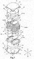
- FIG. 3 is an exploded perspective view illustrating the structure of the reactor 10 in FIG. 1 and illustrates the state where the case 80 is removed.
- the reactor 10 includes: the columnar core bodies 20; the pair of coils 30; bobbins 40; plate-shaped cores 60; fixing brackets 70; and the metal case 8 as major components.
- the columnar core body 20 is formed of a magnetic material such as a ferrite, amorphous, or silicon steel plate. Incidentally, of these magnetic materials, a compact core having an increased density may be formed. Further, in the structure illustrated in FIG. 2 and FIG. 3 , the columnar core body 20 is formed by columnar core members 21, each of which has a shape when seen in a plan view of an oval shape such as a rounded rectangle, being butted each other. However, the shape of the columnar core body 20 when seen in a plan view may be another shape such as a circular shape, an elliptical shape, or a rectangular shape, for example.
- a gap is formed between butted surfaces of the two core members 21, a gap is formed to make a spacer S1 for adjusting an inductance exist, but the core members 21 may be butted each other directly without the spacer S1 existing therebetween.
- the spacer S1 is formed of a material having electrical insulation performance such as resin, for example.
- the two core members 21 are also the same in height. However, these two core members 21 may be different in height.
- a spacer S2 is disposed on the top surface of the columnar core body 20, and on the bottom surface of the columnar core body 20, a spacer S3 is disposed.
- Such spacers S2 and S3 are also formed of a material having electrical insulation performance such as resin, similarly to the above-described spacer S1.
- the paired coils 30 are disposed respectively.
- the pair of coils 30 is formed by winding a flat wire 31.
- a bending portion of the flat wire 31 is formed by edgewise bending, but in the Y-direction (width direction), the coil 30 is provided so that the shape of the coil 30 when seen in a plan view includes semicircular-shaped portions by edgewise bending.
- the flat wire 31 may be bent so as to form various angles such as 90 degrees, for example, other than the semicircular shape.
- the paired coils 30 are each in an independent state, and a constitution in which two terminals 32 exist in the single coil 30 is made. Thus, it is possible to connect the coils 30 in series or in parallel by using these terminals 32.
- the pair of coils 30 may be formed by winding the single flat wire 31.
- the two (paired) coils 30 are formed by winding the single flat wire 31, and the formation is started from the terminal 32 of the one coil 30, and then moves to the other coil 30 via a connecting wire part to be finished at the terminal 32 of the other coil 30B.
- each of the coils 30 is formed by winding the flat wire 31 counterclockwise, for example, from the terminal 32 side of the lower side (Z2 side).
- the two coils 30A and 30B each may be formed by winding the flat wire 31 clockwise, for example, from the terminal 32 side of the lower side (Z2 side).
- both the coils 30A and 30B may be formed in a manner that as for one of the coils 30A and 30B, the flat wire 31 is wound clockwise from the terminal 32 side of the lower side (Z2 side) and as for the other of them, the flat wire 31 is wound counterclockwise from the terminal 32 side of the lower side (Z2 side).
- the coils 30A and 30B are each provided in an oval shape such as a rounded rectangle having a linear portion similarly to the columnar core bodies 20.
- the shape when the coils 30A and 30B are each seen in a plan view may be another shape such as a circular shape, an elliptical shape, or a rectangular shape, for example.
- the terminals 32 of the one coil 30A and the terminals 32 of the other coil 30B are positioned on the lower side (Z2 side) and are also positioned on the upper side (Z1 side). That is, in each of the coils 30A and 30B, the positions of the terminals 32 in the vertical direction (Z-direction) are different.
- an insulating process is performed on the outer peripheral side of each of the coils 30A and 30B.
- a tape having electrical insulation performance is applied on the outer peripheral side of each of the coils 30A and 30B, to ensure the electrical insulation performance.
- the insulation performance of the coils 30A and 30B may be ensured.
- the tape may be applied on the outer peripheral side of each of the coils 30A and 30B.
- FIG. 4 is a perspective view illustrating the shape of a bobbin 40A positioned on the lower side (Z2 side).
- FIG. 5 is a plan view illustrating the shape of the bobbin 40A positioned on the lower side (Z2 side). Note that a bobbin 40A positioned on the upper side (Z1 side) is also the same in shape basically (but in terms of the positional relation, they are vertically symmetrical to each other), and therefore its explanation is omitted.
- the bobbin 40 is provided to form a shape of glasses in its external appearance.
- the bobbin 40 includes a pair of center holes 40a1, and around the respective center holes 40a1, a first annular groove portion 41 and a second annular groove portion 42 are provided.
- the first annular groove portion 41 and the second annular groove portion 42 both include: an inner peripheral wall 43; an outer peripheral wall 44; and a bottom wall 45.
- the first annular groove portion 41 having a recessed groove shape is formed by being surrounded by the inner peripheral wall 43, the outer peripheral wall 44, and the bottom wall 45
- the second annular groove portion 42 having a recessed groove shape is similarly formed by being surrounded by the inner peripheral wall 43, the outer peripheral wall 44, and the bottom wall 45.
- the inner peripheral wall 43 is a portion positioned between the columnar core body 20 and the coil 30, thereby preventing the columnar core body 20 and the coil 30 from directly coming into contact with each other.
- the first annular groove portion 41 and the second annular groove portion 42 are just referred to as annular groove portions 41 and 42 when it is unnecessary to distinguish them from each other in particular.
- a lead-out portion 46 is provided in each of the first annular groove portion 41 and the second annular groove portion 42 of the bobbin 40A.
- the lead-out portion 46 is an opening portion for leading out the terminal 32 of the coil 30 from the annular groove portion 41 or the annular groove portion 42, and is provided in a shape made by cutting out the outer peripheral wall 44.
- the respective lead-out portions 46 are both provided on the front side (Y1 side) in the major axis direction (Y-direction) of the coils 30.
- the paired lead-out portions 46 may be provided on the far side (Y2 side) in the major axis direction (Y-direction) of the coils 30, or a constitution in which the one lead-out portion 46 is provided on the front side (Y1 side) and the other lead-out portion 46 is provided on the far side (Y2 side) may be applied.
- the lead-out portions 46 are provided in places close to both ends in the X-direction, to separate the respective terminals 32 from each other.
- the one coil 30A and the other coil 30B are both formed by winding the flat wire 31 counterclockwise from the terminal 32 side of the lower side (Z2 side).
- the lead-out portion 46 of the annular groove portion 42 is provided to make the terminal 32 extend to the outside in a state facing the X2 side.
- the lead-out portion 46 of the annular groove portion 41 is provided to make the terminal 32 extend to the outside in a state facing the Y1 side.
- a guide wall portion 47 guiding the terminal 32 to extend to the outside.
- the guide wall portion 47 is a portion in which the outer peripheral wall 44 near the lead-out portion 46 is formed into a linear wall so as to direct the terminal 32 to the outside in the extending direction.
- the outer peripheral walls 44 are each provided to make the height thereof become lower than the height of the inner peripheral wall 43. This is due to the following reasons.
- the height of the outer peripheral walls 44 is equal to the height of the inner peripheral wall 43, or is increased more than that, the coils 30 are not easily fitted into the first annular groove portion 41 and the second annular groove portion 42.
- the height of the outer peripheral walls 44 is made lower than the height of the inner peripheral wall 43.
- an outer peripheral projection 48 is provided.
- the outer peripheral projection 48 is a portion for ensuring a space between the case 80 and the coil 30.
- the outer peripheral projection 48 is formed by increasing one portion of the outer peripheral wall 44 in thickness rather than the other portion of the outer peripheral wall 44.
- the outer peripheral projection 48 is set to have a thickness that prevents the case 80 from coming close to the coil 30 without maintaining a specific distance therebetween. This is because when the case 80 comes close to the coil 30 without maintaining a specific distance therebetween, variations are caused in the characteristics of the reactor 10.
- the outer peripheral projections 48 are each provided on the linear portion of the outer peripheral wall 44. Therefore, the outer peripheral projection 48 has a long shape long in the Y-direction. However, such another constitution as a plurality of ones short in length in the Y-direction, for example, are provided along the Y-direction may be employed for the outer peripheral projection 48. Further, in the constitution illustrated in FIG. 4 and FIG. 5 , the outer peripheral projections 48 are each provided integrally with the outer peripheral wall 44. However, the outer peripheral projection 48 may be provided separately from the outer peripheral wall 44 and may be formed in a manner to be retrofitted to the outer peripheral wall 44.
- recessed wall portions 50 are provided.
- Each of the recessed wall portions 50 has such a shape as, of the outer peripheral walls 44 of the bobbin 40A, the portion where the first annular groove portion 41 and the second annular groove portion 42 face each other is recessed toward the center side of the bobbin 40A.
- the recessed wall portions 50 are each provided so that the recess is positioned to the center side rather than the inner peripheral wall 43 positioned at the endmost portion side in the Y-direction.
- the recessed wall portions 50 being provided in the bobbin 40A, the interval between the one coil 30A and the other coil 30B is maintained appropriately and parallel while correcting the surface displacement in each of the coils 30A and 30B and the angular displacement such as a bending angle displacement at an edgewise bending portion.
- the angular displacement such as a bending angle displacement at an edgewise bending portion.
- recessed wall portions 50 are provided in a pair along the Y-direction as illustrated in FIG. 4 and FIG. 5 . Then, a partition wall 49 is also provided so as to connect these paired recessed wall portions 50. This prevents the terminals 32 of the adjacent coils 30 from coming into contact with each other.
- FIG. 6 is a perspective view illustrating the shape of the lower surface side (surface side of the Z2 side; rear surface side) of the bobbin 40A. Note that the bobbin 40A positioned on the upper side (Z1 side) is also the same in shape basically, but an explanation is conducted based on the bobbin 40A positioned on the lower side (Z2 side) here.
- positioning projections 51 are provided so as to project to the lower side (Z2 side).
- the positioning projection 51 is a portion for coming into contact with the plate-shaped core 60 to separate this plate-shaped core 60 from the coils 30. That is, when the plate-shaped core 60 comes too close to the coils 30, an eddy current loss increases.
- the positioning projections 51 are provided.
- the positioning projections 51 are each provided on the rear surface side of curve portions in the first annular groove portion 41 and the second annular groove portion 42. Additionally, the positioning projections 51 are each disposed at an angle of 90 degrees different from the outer peripheral projection 48 in the circumferential direction. Thus, the positioning projection 51 can be provided at four places in total, which further enables stable contacts with the portions near the outer edge of the surface of the plate-shaped core 60.
- the positioning projections 51 each include an abutting portion 51a and a taper portion 51b as illustrated in FIG. 6 .
- the abutting portion 51a is a portion to come into surface contact with the plate-shaped core 60, and is a portion most projecting in the positioning projection 51.
- the taper portion 51b is an inclined wall connecting the abutting portion 51a and the bottom wall 45, and is a portion that gradually goes apart from the rear surface side of the bottom wall 45 from the bottom wall 45 side positioned at the outer peripheral wall 44 side to the abutting portion 51 a positioned at the inner peripheral wall 43 side.
- the paired coils 30 are independent of each other, and a constitution in which the two terminals 32 exist in the single coil 30 is made.
- the pair of coils 30 may be formed by winding the single flat wire 31.
- the side where no terminals 32 exist is formed on either the lower side (Z2 side) or the upper side (Z1 side).
- a bobbin 40B of a different type is preferably used.
- FIG. 7 is an exploded perspective view illustrating the structure of the reactor 10 in FIG. 1 , and is a view illustrating the state where the case 80 is removed and illustrating a constitution in which the bobbin 40B of a type different from the bobbin 40A illustrated in FIG. 4 and FIG. 5 is used and the pair of coils 30 is formed of the single flat wire 31.
- FIG. 8 is a perspective view illustrating the shape of the bobbin 40B of the type different from the bobbin 40A illustrated in FIG. 4 and FIG. 5 .
- FIG. 8 is a perspective view illustrating the shape of the bobbin 40B of the type different from the bobbin 40A illustrated in FIG. 4 and FIG. 5 .
- FIG. 9 is a plan view illustrating the shape of the bobbin 40B of the type different from the bobbin 40A illustrated in FIG. 4 and FIG. 5 .
- the two bobbins 40A and 40B are just referred to as bobbins 40 when it is unnecessary to distinguish them from each other in particular.
- the structure illustrated in FIG. 3 and the structure illustrated in FIG. 7 are both applicable to the reactor 10 illustrated in FIG. 1 basically.
- the bobbin 40B does not include the lead-out portions 46 for leading out the terminal 32 of the coil 30 to the outside, unlike the bobbin 40A of the type illustrated in FIG. 4 and FIG. 5 . Further, the bobbin 40B does not also include the guide wall portions 47 guiding the terminal 32 to extend to the outside.
- the bobbin 40B illustrated in FIG. 7 to FIG. 9 is suitable for the structure that does not include the terminals 32 existing on the upper side (Z1 side) or the lower side (Z2 side) of the pair of coils 30.
- FIG. 7 the structure that does not include the terminals 32 existing on the lower side (Z2 side) of the pair of coils 30 is illustrated.
- the bobbin 40B is disposed on the lower side (Z2 side).
- the bobbin 40B does not also include the partition wall 49 for partition between the first annular groove portion 41 and the second annular groove portion 42. This is due to the following reasons. That is, when the paired coils 30A and 30B are formed by winding the single flat wire 31, the connecting wire part for connecting the two coils 30A and 30B exists, and such a connecting wire part exists between the adjacent coils 30A and 30B. Thus, in order for the connecting wire part to be positioned between the coils 30A and 30B, the bobbin 40B does not also include the partition wall 49 for partition between the first annular groove portion 41 and the second annular groove portion 42.
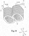
- FIG. 10 is a perspective view illustrating the state where the pair of coils 30 illustrated in FIG. 7 is seen from the lower surface side (Z2 side).
- the connecting wire part 33 connects the coil 30A and the coil 30B by performing edgewise bending. Then, the connecting wire part 33 extends in an oblique direction relative to the Y-direction so as to connect the adjacent first annular groove portion 41 and second annular groove portion 42 of the bobbin 40.
- a constitution in which a twisted portion requiring a dimension in the height direction (Z-direction) does not exist may be employed, or a constitution in which the twisted portion exists may be employed.
- the dimension between the pair of coils 30 and the plate-shaped core 60 of the upper side (Z1 side) and the dimension between the pair of coils 30 and the plate-shaped core 60 of the lower side (Z2 side) are maintained substantially equally.
- the plate-shaped core 60 is a plate-shaped core member having a predetermined thickness.
- This plate-shaped core 60 is provided to have a shape in which corner portions of a rectangle are cut out as illustrated in FIG. 2 and FIG. 3 . Therefore, the plate-shaped core 60 is provided to form an octagon in general when seen in a plan view.
- the shape of the plate-shaped core 60 when seen in a plan view may be another shape such as a circular shape, an elliptical shape, or a rectangular shape, for example.
- Such a plate-shaped core 60 is disposed on each of the upper side (Z1 side) and the lower side (Z2 side) of the pair of columnar core bodies 20.
- a closed magnetic circuit can be formed by the pair of columnar core bodies 20 and the pair of plate-shaped cores 60.
- the plate-shaped cores 60 are formed of the same magnetic material as the columnar core body 20.
- the type of the magnetic material forming the plate-shaped core 60 may be the same type as the columnar core body 20, or may be a type different therefrom.
- FIG. 11 is a bottom view illustrating the state where the bobbin 40A side is seen from the plate-shaped core 60 side, and is a view illustrating the positional relation with the bobbin 40A.
- the plate-shaped core 60 is provided to abut on the abutting portions 51 a of the positioning projections 51. Thereby, the position of the plate-shaped core 60 is determined, and thereby the distance between the pair of coils 30 and the plate-shaped core 60 is maintained.
- the spacers S2 and S3 are disposed between the plate-shaped core 60 on the upper side and the columnar core bodies 20 and between the plate-shaped core 60 on the lower side and the columnar core bodies 20 respectively. By disposing such spacers S2 and S3, a magnetic gap is formed, thereby making it possible to adjust the inductance.
- the plate-shaped core 60 on the upper side and the columnar core bodies 20 and the plate-shaped core 60 on the lower side and the columnar core bodies 20 may be directly butted each other without disposing the spacers S2 and S3 therebetween.
- the fixing bracket 70 corresponding to a fixing means is attached.
- the fixing brackets 70 are each provided for performing positioning of the plate-shaped core 60 and fixing parts from the columnar core bodies 20 to the plate-shaped core 60.
- the fixing bracket 70 is formed by pressing a metal plate or the like, and a plate portion 71 having a large area is provided in each of the fixing brackets 70.
- flange portions 72 are provided so as to rise from the outer edge of the plate portion 71.
- the outer peripheral surface of the plate-shaped core 60 abuts on such a plate portion 71, and thereby positioning of the plate-shaped core 60 is performed.
- the flange portion 72 is provided at four places in total, thereby making the positioning secure.
- the number of places where the flange portion 72 is provided is not limited to four, and the flange portion 72 may be provided at any number of places.
- coupling fixing portions 73 are each provided so as to bend from the flange portion 72 while continuing to the flange portion 72.
- the coupling fixing portions 73 are provided to run substantially parallel to the plate portion 71, but do not have to be substantially parallel to the plate portion 71.
- An insertion hole 73a is provided in each of the coupling fixing portions 73, which enables insertion of a long coupling member.
- the coupling member include a round bar provided with thread grooves on both end sides thereof, and the like, but the coupling member may be another member.
- the insertion holes 73a are not screw holes, but may be screw holes.
- the both end sides of the coupling member are inserted through the insertion holes 73a, and then a nut or the like is screwed down on the both end sides of the coupling member, and thereby a state where the upper and lower fixing brackets 70 are coupled by the coupling member is made.
- the columnar core bodies 20, the coils 30, the bobbins 40, and the plate-shaped cores 60 that are positioned between the upper and lower fixing brackets 70 are sandwiched between these upper and lower fixing brackets 70 to be fixed.
- a constitution in which the upper and lower fixing brackets 70 are not coupled by the coupling member may be employed.
- case fixing portions 74 are also provided in the fixing bracket 70 on the lower side (Z2 side).
- the case fixing portions 74 are each provided so as to rise from the outer edge of the plate portion 71. Therefore, the case fixing portion 74 is provided so as to face the case fixing portion 74.
- the case fixing portion 74 is provided at a place different from the coupling fixing portion 73 on the plate portion 71. Further, in the structure illustrated in FIG. 2 and FIG. 3 , the case fixing portion 74 is provided at two places at 180-degree intervals, but any number of them may be provided.
- a screw hole 74a is provided in each of the case fixing portions 74.
- a screw is screwed into this screw hole 74a from the case 80 side, to thereby establish fixation between the fixing bracket 70 and the case 80.
- a through hole other than the screw hole 74a may be formed.
- the case 80 in this embodiment, is provided to have a box shape with the lower side (Z2 side) surface being opened. Further, as for the case 80, two half cases 81 are put together, to thereby form the box-shaped case 80. In such a case 80, through holes 82 through which a screw is inserted are provided, and the through hole 82 is positioned to the screw hole 74a in the fixing bracket 70. Thus, a screw is inserted into the through hole 82 to be screwed thereinto, to thereby fix the case 80 to the fixing bracket 70.
- the reactor 10 includes: the pair of columnar core bodies 20; the pair of coils 30 disposed on the outer peripheral sides of the columnar core bodies 20; and the bobbins 40.
- the bobbin 40 includes: the inner peripheral walls 43 for partitioning the center hole 40a1; the outer peripheral walls 44 facing the inner peripheral wall 43 on the outer peripheral side rather than the inner peripheral wall 43; and the bottom walls 45 connecting the inner peripheral wall 43 and the outer peripheral wall 44, to thereby form the circular first annular groove portion 41 and second annular groove portion 42 therein.
- the paired coils 30 are fitted into the first annular groove portion 41 and the second annular groove portion 42 respectively.
- the recessed wall portions 50 each having a shape recessed toward the center side of the bobbin 40 are provided, and the recessed wall portion 50 is positioned at the side closer to the center than at least part of the inner peripheral wall 43.
- the variations in the distance between the paired coils 30A and 30B can be prevented, thereby making it possible to securely ensure the insulation between these paired coils 30A and 30B.
- the plate-shaped cores 60 each larger in area than the columnar core bodies 20 are staked so as to sandwich them from both the outer sides in the axial direction (Z-direction).
- the positioning projections 51 are provided on the side opposite to the first annular groove portion 41 and the second annular groove portion 42 of the bottom walls 45 of the bobbin 40. These positioning projections 51 separate the plate-shaped core 60 from the respective coils 30 while being in contact with the plate-shaped core 60. For this reason, it is possible to securely separate the plate-shaped core 60 from the coils 30 by a constant distance or more, thereby enabling suppression of the increase in eddy current loss.
- the reactor 10 includes the metal case 80, and with this case 80, the columnar core bodies 20, the coils 30, and the bobbins 40 are covered. Furthermore, on the outer peripheral walls 44 of each of the bobbins 40, the outer peripheral projections 48 to project in a direction apart from the inner peripheral wall 43 are provided, and by these outer peripheral projections 48, the coils 30 are separated from the metal case 80.
- the outer peripheral walls 44 are each provided to make the height thereof become lower than the height of the inner peripheral wall 43. Therefore, even at the end portions in the vertical direction (Z-direction) of the coils 30, where the electrical insulation tends to be insufficient, the insulation performance can be ensured by the existence of the outer peripheral walls 44. Additionally, when the height of the outer peripheral walls 44 is equal to the height of the inner peripheral wall 43 or is increased more than that, the coils 30 are not easily fitted into the first annular groove portion 41 and the second annular groove portion 42. However, when the outer peripheral walls 44 are each provided to make the height thereof become lower than the height of the inner peripheral wall 43 as described above, the coils 30 are easily fitted into the first annular groove portion 41 and the second annular groove portion 42. Thus, it is possible to improve assembly performance of the reactor 10 and improve production efficiency.
- the fixing bracket 70 is provided on each of both the outer sides in the axial direction rather than the paired plate-shaped cores 60 (on the side lower than the plate-shaped core 60 of the lower side and on the upper side rather than the plate-shaped core 60 of the upper side). Then, the columnar core bodies 20, the coils 30, the bobbins 40, and the plate-shaped cores 6 are sandwiched by the pair of fixing brackets 70. For this reason, the columnar core bodies 20, the coils 30, the bobbins 40, and the plate-shaped cores 6 can be sandwiched and fixed by the pair of fixing brackets 70, resulting in that it is possible to further securely prevent occurrence of distance variations among these.
- the flat wire 31 is used to form the coils 30 .
- the square wire is not limited to the flat wire 31, and may be, for example, a square wire whose cross section is square or a square wire including an oval element such as an ellipse.
- a round wire may be used.
- the reactor which is one kind of a coil part
- the present invention may be applied to other coil parts.
- other coil parts are a transformer, a common mode choke coil, a normal mode choke coil, and the like.
- a bobbin in a different form may be used, or bobbins in different forms may be used in combination.
- a pair of bobbins in a form in which the partition wall 49 is removed from the bobbin 40A may be used, or the bobbin in a form in which the partition wall 49 is removed from the bobbin 40A and either the bobbin 40A or the bobbin 40B may be used in combination.
- the bobbin 40 including the two annular groove portions of the first annular groove portion 41 and the second annular groove portion 42 as an annular groove portion is explained.
- the bobbin is not limited to the one including the two annular groove portions, and may employ a constitution including three or more annular groove portions. In this case, a constitution in which three or more coils are also included is made.
- the structure including the columnar core bodies 20 and the plate-shaped cores 60 is explained.
- cores in different forms may be used.
- bar-shaped cores may be used, and in place of the plate-shaped cores 60, bar-shaped cores may be used.
- the case of using the pair of fixing brackets 70 as a fixing means is explained.
- a means other than the fixing brackets 70 may be used.
- brackets in a different form may be used, a belt and a wire may be used, or the metal case 80 may be used as a fixing means.
Landscapes
- Engineering & Computer Science (AREA)
- Power Engineering (AREA)
- Insulating Of Coils (AREA)
- Coils Or Transformers For Communication (AREA)
Abstract
Description
- The present invention relates to a reactor or inductor used in an electrical power circuitry.
- In recent years, a reactor is used broadly for a converter of a hybrid vehicle, a power conditioner of a solar power generation system, and the like. As such a reactor, there is one disclosed in
PTL 1, for example. According toPTL 1, since a coil made by winding a flat wire of a metal conductor has spring nature basically, it possibly becomes extended or contracted to cause characteristics of the reactor fluctuate. Further, it is necessary to ensure insulation of the coil from a core. Therefore, in the structure disclosed inPTL 1, a bobbin is fitted in each of end portion sides of the coil to prevent the characteristic fluctuations and ensure the insulation between the coil and the core. - {PTL 1}
JP 5105079 B - By the way, in the structure of
PTL 1, projecting frame portions (inner peripheral walls) exist on the inner peripheral side. However, the bobbin having only such projecting frame portions is not sufficient to maintain an interval between coils and an interval between cores. Thus, the characteristics of the reactor vary due to the variations in distance between the coils and the variations in distance between the cores, resulting in that dispersion of quality may be caused. Further, when the variations in distance between the coils occur, the insulation between the coils may become insufficient. - The present invention is made in view of such problems, and an object thereof is to provide a reactor capable of maintaining intervals between coils and between cores and capable of securely ensuring insulation between the coils.
- To solve the above-described problems, a reactor according to the present invention includes: a pair of columnar core bodies formed of a magnetic material; a pair of coils disposed on outer peripheral sides of the columnar core bodies and formed by winding a flat wire; and a bobbin including: inner peripheral walls for partitioning a center hole; outer peripheral walls provided at outer peripheral sides from the inner peripheral walls and facing the inner peripheral walls respectively; and bottom walls coupling the inner peripheral wall and the outer peripheral walls, to thereby form a first annular groove portion and a second annular groove portion each having a circular shape therein, for the pair of coils to be fitted into the first annular groove portion and the second annular groove portion respectively, in which: recessed wall portions, each having a shape recessed toward the center side of the bobbin, are provided at a portion of the outer peripheral walls where the first annular groove portion and the second annular groove portion face each other, and the recessed wall portions are each positioned on a side closer to the center than at least part of the inner peripheral walls.
- The reactor of the present invention is preferable in that, plate-shaped cores, each formed of a magnetic material and being larger in area than the columnar core bodies, are stacked on the columnar core bodies to sandwich the columnar core bodies from both outer sides thereof in an axial direction, and positioning projections are provided on a side opposite to the first annular groove portion and the second annular groove portion of the bottom walls, contacting with the plate-shaped cores and separating the plate-shaped cores from the coils.
- The reactor of the present invention is further preferable in that, a metal case is provided for covering the columnar core bodies, the coils, and the bobbin, and outer peripheral projections are provided on the outer peripheral walls respectively, projecting in a direction apart from the inner peripheral walls to separate the coils from the case.
- The reactor of the present invention is further preferable in that the outer peripheral walls have a height lower than a height of the inner peripheral walls.
- The present invention is further preferable in that fixing means are provided on both outer sides in the axial direction of the pair of plate-shaped cores, and the columnar core bodies, the coils, the bobbin, and the plate-shaped cores are sandwiched by the pair of fixing means.
- According to the present invention, it makes it possible for the reactor to maintain intervals between coils and between cores and securely ensure insulation between the coils.
-
- {
Fig. 1} FIG. 1 is a perspective view illustrating a structure of a reactor according to one embodiment of the present invention; - {
Fig. 2} FIG. 2 is a perspective view illustrating the structure of the reactor according to the embodiment of the present invention, and is a view illustrating a structure obtained after a case is removed; - {
Fig. 3} FIG. 3 is an exploded perspective view illustrating the structure of the reactor inFIG. 1 and illustrates a state where the case is removed; - {
Fig. 4} FIG. 4 is a perspective view illustrating a shape of a bobbin positioned on a lower side in the reactor inFIG. 1 ; - {
Fig. 5} FIG. 5 is a plan view illustrating the shape of the bobbin positioned on the lower side in the reactor inFIG. 1 ; - {
Fig. 6} FIG. 6 is a perspective view illustrating a lower surface side shape of the bobbin in the reactor inFIG. 1 ; - {
Fig. 7} FIG. 7 is an exploded perspective view illustrating the structure of the reactor inFIG. 1 , and is a view illustrating the state where the case is removed and illustrating a constitution in which a bobbin of a type different from the bobbin illustrated inFIG. 4 andFIG. 5 is used and a pair of coils is formed of a single flat wire; - {
Fig. 8} FIG. 8 is a perspective view illustrating a shape of the bobbin of the type different from the bobbin illustrated inFIG. 4 andFIG. 5 ; - {
Fig. 9} FIG. 9 is a plan view illustrating the shape of the bobbin of the type different from the bobbin illustrated inFIG. 4 andFIG. 5 ; - {
Fig. 10} FIG. 10 is a perspective view illustrating a state where the pair of coils illustrated inFIG. 7 is seen from the lower surface side; and - {
Fig. 11} FIG. 11 is a bottom view illustrating a state where a bobbin 40A side is seen from a plate-shaped core 60 side, and is a view illustrating the positional relation with the bobbin in the reactor inFIG. 1 . - Hereinafter, a
reactor 10 according to one embodiment of the present invention will be explained based on the drawings. - Note that in the following explanation, it is assumed that the axial direction of coils 30 and
columnar core bodies 20 is the vertical direction (Z-direction), the side covered with acase 80 is a Z1 side (upper side), and the opening side of thecase 80 opposite thereto is a Z2 side (lower side). It is further assumed that inFIG. 2 andFIG. 3 , the direction in which the pair of coils 30 is arranged side by side is an X-direction, the right front side inFIG. 2 andFIG. 3 is an X1 side, and the side opposite thereto is an X2 side. It is further assumed that the direction perpendicular to the X-direction and the Z-direction is a Y-direction, and the right far side inFIG. 1 to FIG. 3 is a Y1 side and the left front side opposite thereto is a Y2 side. -
FIG. 1 is a perspective view illustrating the structure of thereactor 10.FIG. 2 is a perspective view illustrating the structure of thereactor 10 and is a view illustrating the state where thecase 80 is removed.FIG. 3 is an exploded perspective view illustrating the structure of thereactor 10 inFIG. 1 and illustrates the state where thecase 80 is removed. As illustrated inFIG. 1 to FIG. 3 , thereactor 10 includes: thecolumnar core bodies 20; the pair of coils 30; bobbins 40; plate-shaped cores 60;fixing brackets 70; and the metal case 8 as major components. - The
columnar core body 20 is formed of a magnetic material such as a ferrite, amorphous, or silicon steel plate. Incidentally, of these magnetic materials, a compact core having an increased density may be formed. Further, in the structure illustrated inFIG. 2 andFIG. 3 , thecolumnar core body 20 is formed bycolumnar core members 21, each of which has a shape when seen in a plan view of an oval shape such as a rounded rectangle, being butted each other. However, the shape of thecolumnar core body 20 when seen in a plan view may be another shape such as a circular shape, an elliptical shape, or a rectangular shape, for example. - Here, between butted surfaces of the two
core members 21, a gap is formed to make a spacer S1 for adjusting an inductance exist, but thecore members 21 may be butted each other directly without the spacer S1 existing therebetween. The spacer S1 is formed of a material having electrical insulation performance such as resin, for example. Further, the twocore members 21 are also the same in height. However, these twocore members 21 may be different in height. - Further, on the top surface of the
columnar core body 20, a spacer S2 is disposed, and on the bottom surface of thecolumnar core body 20, a spacer S3 is disposed. Such spacers S2 and S3 are also formed of a material having electrical insulation performance such as resin, similarly to the above-described spacer S1. - Further, on the outer peripheral sides of the
columnar core bodies 20, the paired coils 30 are disposed respectively. The pair of coils 30 is formed by winding aflat wire 31. At this time, a bending portion of theflat wire 31 is formed by edgewise bending, but in the Y-direction (width direction), the coil 30 is provided so that the shape of the coil 30 when seen in a plan view includes semicircular-shaped portions by edgewise bending. However, as for the edgewise bending, theflat wire 31 may be bent so as to form various angles such as 90 degrees, for example, other than the semicircular shape. - In this embodiment, as illustrated in
FIG. 2 andFIG. 3 , the paired coils 30 are each in an independent state, and a constitution in which twoterminals 32 exist in the single coil 30 is made. Thus, it is possible to connect the coils 30 in series or in parallel by using theseterminals 32. - However, the pair of coils 30 may be formed by winding the single
flat wire 31. In this case, the two (paired) coils 30 are formed by winding the singleflat wire 31, and the formation is started from theterminal 32 of the one coil 30, and then moves to the other coil 30 via a connecting wire part to be finished at theterminal 32 of the other coil 30B. - Note that in this embodiment, the winding direction of the one coil 30 (the coil 30 on the X1 side; to be referred to as coil 30A) and the winding direction of the other coil 30 (the coil 30 on the X2 side; to be referred to as coil 30B) are the same direction. Concretely, in the structure illustrated in
FIG. 2 andFIG. 3 , each of the coils 30 is formed by winding theflat wire 31 counterclockwise, for example, from the terminal 32 side of the lower side (Z2 side). However, the two coils 30A and 30B each may be formed by winding theflat wire 31 clockwise, for example, from the terminal 32 side of the lower side (Z2 side). Further, both the coils 30A and 30B may be formed in a manner that as for one of the coils 30A and 30B, theflat wire 31 is wound clockwise from the terminal 32 side of the lower side (Z2 side) and as for the other of them, theflat wire 31 is wound counterclockwise from the terminal 32 side of the lower side (Z2 side). - Note that when the coils 30A and 30B are seen in a plan view, they are each provided in an oval shape such as a rounded rectangle having a linear portion similarly to the
columnar core bodies 20. However, the shape when the coils 30A and 30B are each seen in a plan view may be another shape such as a circular shape, an elliptical shape, or a rectangular shape, for example. - Further, the
terminals 32 of the one coil 30A and theterminals 32 of the other coil 30B are positioned on the lower side (Z2 side) and are also positioned on the upper side (Z1 side). That is, in each of the coils 30A and 30B, the positions of theterminals 32 in the vertical direction (Z-direction) are different. - Note that an insulating process is performed on the outer peripheral side of each of the coils 30A and 30B. Concretely, a tape having electrical insulation performance is applied on the outer peripheral side of each of the coils 30A and 30B, to ensure the electrical insulation performance. However, in place of applying the tape on the outer peripheral side of each of the coils 30A and 30B, for example, by varnish impregnation or the like, the insulation performance of the coils 30A and 30B may be ensured. Further, together with the varnish impregnation process, the tape may be applied on the outer peripheral side of each of the coils 30A and 30B.
- Next, the bobbins 40 are explained.
FIG. 4 is a perspective view illustrating the shape of a bobbin 40A positioned on the lower side (Z2 side).FIG. 5 is a plan view illustrating the shape of the bobbin 40A positioned on the lower side (Z2 side). Note that a bobbin 40A positioned on the upper side (Z1 side) is also the same in shape basically (but in terms of the positional relation, they are vertically symmetrical to each other), and therefore its explanation is omitted. - As illustrated in
FIG. 4 andFIG. 5 , the bobbin 40 is provided to form a shape of glasses in its external appearance. Concretely, the bobbin 40 includes a pair of center holes 40a1, and around the respective center holes 40a1, a firstannular groove portion 41 and a secondannular groove portion 42 are provided. The firstannular groove portion 41 and the secondannular groove portion 42 both include: an innerperipheral wall 43; an outerperipheral wall 44; and abottom wall 45. Then, the firstannular groove portion 41 having a recessed groove shape is formed by being surrounded by the innerperipheral wall 43, the outerperipheral wall 44, and thebottom wall 45, and the secondannular groove portion 42 having a recessed groove shape is similarly formed by being surrounded by the innerperipheral wall 43, the outerperipheral wall 44, and thebottom wall 45. - Here, the inner
peripheral wall 43 is a portion positioned between thecolumnar core body 20 and the coil 30, thereby preventing thecolumnar core body 20 and the coil 30 from directly coming into contact with each other. Note that the firstannular groove portion 41 and the secondannular groove portion 42 are just referred to asannular groove portions - Here, in each of the first
annular groove portion 41 and the secondannular groove portion 42 of the bobbin 40A, a lead-outportion 46 is provided. The lead-outportion 46 is an opening portion for leading out theterminal 32 of the coil 30 from theannular groove portion 41 or theannular groove portion 42, and is provided in a shape made by cutting out the outerperipheral wall 44. In the constitution illustrated inFIG. 4 andFIG. 5 , the respective lead-outportions 46 are both provided on the front side (Y1 side) in the major axis direction (Y-direction) of the coils 30. However, the paired lead-outportions 46 may be provided on the far side (Y2 side) in the major axis direction (Y-direction) of the coils 30, or a constitution in which the one lead-outportion 46 is provided on the front side (Y1 side) and the other lead-outportion 46 is provided on the far side (Y2 side) may be applied. - Further, in the constitution illustrated in
FIG. 4 , the lead-outportions 46 are provided in places close to both ends in the X-direction, to separate therespective terminals 32 from each other. Here, in this embodiment, the one coil 30A and the other coil 30B are both formed by winding theflat wire 31 counterclockwise from the terminal 32 side of the lower side (Z2 side). Thus, the lead-outportion 46 of theannular groove portion 42 is provided to make the terminal 32 extend to the outside in a state facing the X2 side. Further, the lead-outportion 46 of theannular groove portion 41 is provided to make the terminal 32 extend to the outside in a state facing the Y1 side. - Incidentally, as is clear from
FIG. 4 andFIG. 5 , in the vicinity of each of the lead-outportions 46 of the bobbin 40A, there is provided aguide wall portion 47 guiding the terminal 32 to extend to the outside. Theguide wall portion 47 is a portion in which the outerperipheral wall 44 near the lead-outportion 46 is formed into a linear wall so as to direct the terminal 32 to the outside in the extending direction. - Here, in this embodiment, the outer
peripheral walls 44 are each provided to make the height thereof become lower than the height of the innerperipheral wall 43. This is due to the following reasons. - That is, when the outer
peripheral wall 44 does not exist at all tentatively, a place that is not insulated sufficiently is formed at the lower side (Z2 side) of the coil 30. This is because in this embodiment, a tape is applied on the outer peripheral side of the coil 30, thereby ensuring the electrical insulation performance of the coil 30, but at the endmost portion of the coil 30, theflat wire 31 is not stacked on one side (the lower side in this case; Z2 side), and thus the endmost portion is not fixed by the tape and the insulation is liable to be cancelled. Further, at the endmost portion side of the coil 30, the region where the tape is applied is smaller than any other region due to existence of the portion to lead out the terminal 32 to the outside, or the like. Thus, providing the outerperipheral wall 44 ensures the insulation performance at the lower side (Z2 side) of the coil 30. - On the other hand, when the height of the outer
peripheral walls 44 is equal to the height of the innerperipheral wall 43, or is increased more than that, the coils 30 are not easily fitted into the firstannular groove portion 41 and the secondannular groove portion 42. Thus, in order for the coils 30 to be fitted into the firstannular groove portion 41 and the secondannular groove portion 42 easily while ensuring the insulation performance at the lower side (Z2 side) of the coils 30, the height of the outerperipheral walls 44 is made lower than the height of the innerperipheral wall 43. - Further, of the outer
peripheral walls 44, on each of the sides where the firstannular groove portion 41 and the secondannular groove portion 42 are not adjacent to each other (separated sides), an outerperipheral projection 48 is provided. The outerperipheral projection 48 is a portion for ensuring a space between thecase 80 and the coil 30. Concretely, the outerperipheral projection 48 is formed by increasing one portion of the outerperipheral wall 44 in thickness rather than the other portion of the outerperipheral wall 44. Furthermore, the outerperipheral projection 48 is set to have a thickness that prevents thecase 80 from coming close to the coil 30 without maintaining a specific distance therebetween. This is because when thecase 80 comes close to the coil 30 without maintaining a specific distance therebetween, variations are caused in the characteristics of thereactor 10. - In this embodiment, the outer
peripheral projections 48 are each provided on the linear portion of the outerperipheral wall 44. Therefore, the outerperipheral projection 48 has a long shape long in the Y-direction. However, such another constitution as a plurality of ones short in length in the Y-direction, for example, are provided along the Y-direction may be employed for the outerperipheral projection 48. Further, in the constitution illustrated inFIG. 4 andFIG. 5 , the outerperipheral projections 48 are each provided integrally with the outerperipheral wall 44. However, the outerperipheral projection 48 may be provided separately from the outerperipheral wall 44 and may be formed in a manner to be retrofitted to the outerperipheral wall 44. - Further, in the bobbin 40A, recessed
wall portions 50 are provided. Each of the recessedwall portions 50 has such a shape as, of the outerperipheral walls 44 of the bobbin 40A, the portion where the firstannular groove portion 41 and the secondannular groove portion 42 face each other is recessed toward the center side of the bobbin 40A. As for the degree of such a recess, as illustrated inFIG. 5 , the recessedwall portions 50 are each provided so that the recess is positioned to the center side rather than the innerperipheral wall 43 positioned at the endmost portion side in the Y-direction. Thus, each angular displacement in the coils 30A and 30B is well prevented. - Here, there is created the following merit when the recessed
wall portions 50 exist. That is, at the lower side (Z2 side) of the coil 30A and the coil 30B, a potential difference is often high. When at such a place having a high potential difference, a surface displacement and an angular displacement such as a bending angle displacement at an edgewise bending portion occur, the distance between the two coils 30A and 30B varies, to thereby cause the variations in characteristics of thereactor 10, which may cause the dispersion of quality. - However, by the recessed
wall portions 50 being provided in the bobbin 40A, the interval between the one coil 30A and the other coil 30B is maintained appropriately and parallel while correcting the surface displacement in each of the coils 30A and 30B and the angular displacement such as a bending angle displacement at an edgewise bending portion. Thus, it becomes possible to prevent the variations in the distance between the two coils 30A and 30B. This prevents the characteristics of thereactor 10 from varying to thereby suppress the dispersion of quality. - Note that the recessed
wall portions 50 are provided in a pair along the Y-direction as illustrated inFIG. 4 andFIG. 5 . Then, apartition wall 49 is also provided so as to connect these paired recessedwall portions 50. This prevents theterminals 32 of the adjacent coils 30 from coming into contact with each other. -
FIG. 6 is a perspective view illustrating the shape of the lower surface side (surface side of the Z2 side; rear surface side) of the bobbin 40A. Note that the bobbin 40A positioned on the upper side (Z1 side) is also the same in shape basically, but an explanation is conducted based on the bobbin 40A positioned on the lower side (Z2 side) here. - As illustrated in
FIG. 6 , on the lower surface side of the bobbin 40A,positioning projections 51 are provided so as to project to the lower side (Z2 side). Thepositioning projection 51 is a portion for coming into contact with the plate-shapedcore 60 to separate this plate-shapedcore 60 from the coils 30. That is, when the plate-shapedcore 60 comes too close to the coils 30, an eddy current loss increases. Thus, in order to securely separate the plate-shapedcore 60 and the coils 30 by a constant distance or more to reduce the eddy current loss, thepositioning projections 51 are provided. - Note that in the constitution illustrated in
FIG. 6 , thepositioning projections 51 are each provided on the rear surface side of curve portions in the firstannular groove portion 41 and the secondannular groove portion 42. Additionally, thepositioning projections 51 are each disposed at an angle of 90 degrees different from the outerperipheral projection 48 in the circumferential direction. Thus, thepositioning projection 51 can be provided at four places in total, which further enables stable contacts with the portions near the outer edge of the surface of the plate-shapedcore 60. - The
positioning projections 51 each include an abuttingportion 51a and ataper portion 51b as illustrated inFIG. 6 . The abuttingportion 51a is a portion to come into surface contact with the plate-shapedcore 60, and is a portion most projecting in thepositioning projection 51. Further, thetaper portion 51b is an inclined wall connecting the abuttingportion 51a and thebottom wall 45, and is a portion that gradually goes apart from the rear surface side of thebottom wall 45 from thebottom wall 45 side positioned at the outerperipheral wall 44 side to the abuttingportion 51 a positioned at the innerperipheral wall 43 side. - Note that in the case of using the bobbin 40A illustrated in
FIG. 4 to FIG. 6 , the paired coils 30 are independent of each other, and a constitution in which the twoterminals 32 exist in the single coil 30 is made. However, the pair of coils 30 may be formed by winding the singleflat wire 31. In this case, in the pair of coils 30 illustrated inFIG. 2 andFIG. 3 , the side where noterminals 32 exist is formed on either the lower side (Z2 side) or the upper side (Z1 side). In this case, such a bobbin as illustrated inFIG. 4 to FIG. 6 may be used, but a bobbin 40B of a different type is preferably used. - Note that the
reactor 10 using the pair of coils 30 formed by winding the singleflat wire 31 is illustrated inFIG. 7. FIG. 7 is an exploded perspective view illustrating the structure of thereactor 10 inFIG. 1 , and is a view illustrating the state where thecase 80 is removed and illustrating a constitution in which the bobbin 40B of a type different from the bobbin 40A illustrated inFIG. 4 andFIG. 5 is used and the pair of coils 30 is formed of the singleflat wire 31.FIG. 8 is a perspective view illustrating the shape of the bobbin 40B of the type different from the bobbin 40A illustrated inFIG. 4 andFIG. 5 .FIG. 9 is a plan view illustrating the shape of the bobbin 40B of the type different from the bobbin 40A illustrated inFIG. 4 andFIG. 5 . Note that in the following explanation, the two bobbins 40A and 40B are just referred to as bobbins 40 when it is unnecessary to distinguish them from each other in particular. Further, the structure illustrated inFIG. 3 and the structure illustrated inFIG. 7 are both applicable to thereactor 10 illustrated inFIG. 1 basically. - As illustrated in
FIG. 7 to FIG. 9 , the bobbin 40B does not include the lead-outportions 46 for leading out theterminal 32 of the coil 30 to the outside, unlike the bobbin 40A of the type illustrated inFIG. 4 andFIG. 5 . Further, the bobbin 40B does not also include theguide wall portions 47 guiding the terminal 32 to extend to the outside. Thus, the bobbin 40B illustrated inFIG. 7 to FIG. 9 is suitable for the structure that does not include theterminals 32 existing on the upper side (Z1 side) or the lower side (Z2 side) of the pair of coils 30. - Note that in
FIG. 7 , the structure that does not include theterminals 32 existing on the lower side (Z2 side) of the pair of coils 30 is illustrated. Thus, inFIG. 7 , the bobbin 40B is disposed on the lower side (Z2 side). - Further, the bobbin 40B does not also include the
partition wall 49 for partition between the firstannular groove portion 41 and the secondannular groove portion 42. This is due to the following reasons. That is, when the paired coils 30A and 30B are formed by winding the singleflat wire 31, the connecting wire part for connecting the two coils 30A and 30B exists, and such a connecting wire part exists between the adjacent coils 30A and 30B. Thus, in order for the connecting wire part to be positioned between the coils 30A and 30B, the bobbin 40B does not also include thepartition wall 49 for partition between the firstannular groove portion 41 and the secondannular groove portion 42. - Here, in the
reactor 10 illustrated inFIG. 7 , the pair of coils 30 is formed by winding the singleflat wire 31, and in this case, the connecting wire part that connects the coil 30A and the coil 30B (to be referred to as connecting wire part 33) has a constitution illustrated inFIG. 10. FIG. 10 is a perspective view illustrating the state where the pair of coils 30 illustrated inFIG. 7 is seen from the lower surface side (Z2 side). As illustrated inFIG. 10 , the connectingwire part 33 connects the coil 30A and the coil 30B by performing edgewise bending. Then, the connectingwire part 33 extends in an oblique direction relative to the Y-direction so as to connect the adjacent firstannular groove portion 41 and secondannular groove portion 42 of the bobbin 40. - Note that for the above-described
connecting wire part 33, a constitution in which a twisted portion requiring a dimension in the height direction (Z-direction) does not exist may be employed, or a constitution in which the twisted portion exists may be employed. When the constitution in which the twisted portion does not exist is employed, the dimension between the pair of coils 30 and the plate-shapedcore 60 of the upper side (Z1 side) and the dimension between the pair of coils 30 and the plate-shapedcore 60 of the lower side (Z2 side) are maintained substantially equally. Thus, it becomes possible to prevent deterioration of the balance in the vertical direction of thereactor 10, and thereby it is possible to prevent the characteristics of thereactor 10 from varying. On the other hand, when the constitution in which the twisted portion exists is employed, it is possible to align the direction of edgewise bending in the coil 30A and the direction of edgewise bending in the coil 30B (to apply right bending or left bending to both the coils 30A and 30B, for example). Thus, it is possible to prevent resetting of a processing machine to perform edgewise bending and further omit an additional constitution to the processing machine. - Next, the plate-shaped
core 60 is explained. As illustrated inFIG. 2 andFIG. 3 , the plate-shapedcore 60 is a plate-shaped core member having a predetermined thickness. This plate-shapedcore 60 is provided to have a shape in which corner portions of a rectangle are cut out as illustrated inFIG. 2 andFIG. 3 . Therefore, the plate-shapedcore 60 is provided to form an octagon in general when seen in a plan view. However, the shape of the plate-shapedcore 60 when seen in a plan view may be another shape such as a circular shape, an elliptical shape, or a rectangular shape, for example. - Such a plate-shaped
core 60 is disposed on each of the upper side (Z1 side) and the lower side (Z2 side) of the pair ofcolumnar core bodies 20. Thus, a closed magnetic circuit can be formed by the pair ofcolumnar core bodies 20 and the pair of plate-shapedcores 60. Note that the plate-shapedcores 60 are formed of the same magnetic material as thecolumnar core body 20. Here, the type of the magnetic material forming the plate-shapedcore 60 may be the same type as thecolumnar core body 20, or may be a type different therefrom. -
FIG. 11 is a bottom view illustrating the state where the bobbin 40A side is seen from the plate-shapedcore 60 side, and is a view illustrating the positional relation with the bobbin 40A. As illustrated inFIG. 11 , the plate-shapedcore 60 is provided to abut on the abuttingportions 51 a of thepositioning projections 51. Thereby, the position of the plate-shapedcore 60 is determined, and thereby the distance between the pair of coils 30 and the plate-shapedcore 60 is maintained. - Note that the spacers S2 and S3 are disposed between the plate-shaped
core 60 on the upper side and thecolumnar core bodies 20 and between the plate-shapedcore 60 on the lower side and thecolumnar core bodies 20 respectively. By disposing such spacers S2 and S3, a magnetic gap is formed, thereby making it possible to adjust the inductance. However, the plate-shapedcore 60 on the upper side and thecolumnar core bodies 20 and the plate-shapedcore 60 on the lower side and thecolumnar core bodies 20 may be directly butted each other without disposing the spacers S2 and S3 therebetween. - Further, on each of the plate-shaped
cores 60, the fixingbracket 70 corresponding to a fixing means is attached. The fixingbrackets 70 are each provided for performing positioning of the plate-shapedcore 60 and fixing parts from thecolumnar core bodies 20 to the plate-shapedcore 60. Concretely, the fixingbracket 70 is formed by pressing a metal plate or the like, and aplate portion 71 having a large area is provided in each of the fixingbrackets 70. - Further,
flange portions 72 are provided so as to rise from the outer edge of theplate portion 71. The outer peripheral surface of the plate-shapedcore 60 abuts on such aplate portion 71, and thereby positioning of the plate-shapedcore 60 is performed. In the structure illustrated inFIG. 2 andFIG. 3 , theflange portion 72 is provided at four places in total, thereby making the positioning secure. However, the number of places where theflange portion 72 is provided is not limited to four, and theflange portion 72 may be provided at any number of places. - Incidentally, coupling fixing
portions 73 are each provided so as to bend from theflange portion 72 while continuing to theflange portion 72. In the structure illustrated inFIG. 2 andFig. 3 , thecoupling fixing portions 73 are provided to run substantially parallel to theplate portion 71, but do not have to be substantially parallel to theplate portion 71. Aninsertion hole 73a is provided in each of thecoupling fixing portions 73, which enables insertion of a long coupling member. Examples of the coupling member include a round bar provided with thread grooves on both end sides thereof, and the like, but the coupling member may be another member. Further, theinsertion holes 73a are not screw holes, but may be screw holes. - Then, positioning of the
insertion hole 73a in thecoupling fixing portion 73 on the upper side (Z1 side) and theinsertion hole 73a in thecoupling fixing portion 73 on the lower side (Z2 side) is performed, the both end sides of the coupling member are inserted through theinsertion holes 73a, and then a nut or the like is screwed down on the both end sides of the coupling member, and thereby a state where the upper andlower fixing brackets 70 are coupled by the coupling member is made. Thus, thecolumnar core bodies 20, the coils 30, the bobbins 40, and the plate-shapedcores 60 that are positioned between the upper andlower fixing brackets 70 are sandwiched between these upper andlower fixing brackets 70 to be fixed. However, a constitution in which the upper andlower fixing brackets 70 are not coupled by the coupling member may be employed. - Further,
case fixing portions 74 are also provided in the fixingbracket 70 on the lower side (Z2 side). Thecase fixing portions 74 are each provided so as to rise from the outer edge of theplate portion 71. Therefore, thecase fixing portion 74 is provided so as to face thecase fixing portion 74. Note that thecase fixing portion 74 is provided at a place different from thecoupling fixing portion 73 on theplate portion 71. Further, in the structure illustrated inFIG. 2 andFIG. 3 , thecase fixing portion 74 is provided at two places at 180-degree intervals, but any number of them may be provided. - In each of the
case fixing portions 74, ascrew hole 74a is provided. A screw is screwed into thisscrew hole 74a from thecase 80 side, to thereby establish fixation between the fixingbracket 70 and thecase 80. However, a through hole other than thescrew hole 74a may be formed. - Further, the outer peripheral side of the
reactor 10 is covered with themetal case 80. Thecase 80, in this embodiment, is provided to have a box shape with the lower side (Z2 side) surface being opened. Further, as for thecase 80, twohalf cases 81 are put together, to thereby form the box-shapedcase 80. In such acase 80, throughholes 82 through which a screw is inserted are provided, and the throughhole 82 is positioned to thescrew hole 74a in the fixingbracket 70. Thus, a screw is inserted into the throughhole 82 to be screwed thereinto, to thereby fix thecase 80 to the fixingbracket 70. - Incidentally, a constitution in which such a
case 80 is not provided but is omitted may be employed for thereactor 10. - In the above structure, the
reactor 10 includes: the pair ofcolumnar core bodies 20; the pair of coils 30 disposed on the outer peripheral sides of thecolumnar core bodies 20; and the bobbins 40. Then, the bobbin 40 includes: the innerperipheral walls 43 for partitioning the center hole 40a1; the outerperipheral walls 44 facing the innerperipheral wall 43 on the outer peripheral side rather than the innerperipheral wall 43; and thebottom walls 45 connecting the innerperipheral wall 43 and the outerperipheral wall 44, to thereby form the circular firstannular groove portion 41 and secondannular groove portion 42 therein. Further, the paired coils 30 are fitted into the firstannular groove portion 41 and the secondannular groove portion 42 respectively. Then, at the portion of the outerperipheral walls 44, where the firstannular groove portion 41 and the secondannular groove portion 42 face each other, the recessedwall portions 50 each having a shape recessed toward the center side of the bobbin 40 are provided, and the recessedwall portion 50 is positioned at the side closer to the center than at least part of the innerperipheral wall 43. - For this reason, it is possible to maintain the interval between the one coil 30A and the other coil 30B appropriately and parallel while correcting a surface displacement in each of the coils 30A and 30B and an angular displacement such as a bending angle displacement at an edgewise bending portion. Thus, it becomes possible to prevent the variations in the distance between the two coils 30A and 30B. This makes it possible to prevent the characteristics of the
reactor 10 from varying, resulting in that it is possible to suppress occurrence of quality dispersion in thereactor 10. - Further, the variations in the distance between the paired coils 30A and 30B can be prevented, thereby making it possible to securely ensure the insulation between these paired coils 30A and 30B.
- Further, in this embodiment, on the
columnar core bodies 20, the plate-shapedcores 60 each larger in area than thecolumnar core bodies 20 are staked so as to sandwich them from both the outer sides in the axial direction (Z-direction). Moreover, on the side opposite to the firstannular groove portion 41 and the secondannular groove portion 42 of thebottom walls 45 of the bobbin 40, thepositioning projections 51 are provided. Thesepositioning projections 51 separate the plate-shapedcore 60 from the respective coils 30 while being in contact with the plate-shapedcore 60. For this reason, it is possible to securely separate the plate-shapedcore 60 from the coils 30 by a constant distance or more, thereby enabling suppression of the increase in eddy current loss. - Further, in this embodiment, the
reactor 10 includes themetal case 80, and with thiscase 80, thecolumnar core bodies 20, the coils 30, and the bobbins 40 are covered. Furthermore, on the outerperipheral walls 44 of each of the bobbins 40, the outerperipheral projections 48 to project in a direction apart from the innerperipheral wall 43 are provided, and by these outerperipheral projections 48, the coils 30 are separated from themetal case 80. - For this reason, it becomes possible to ensure a space with a constant distance or more between the
metal case 80 and the coils 30. This makes it possible to prevent that themetal case 80 and the coils 30 come close to each other to cause variations in the characteristics of thereactor 10. Further, it becomes possible to further securely ensure the insulation between themetal case 80 and the coils 30. - Further, in this embodiment, the outer
peripheral walls 44 are each provided to make the height thereof become lower than the height of the innerperipheral wall 43. Therefore, even at the end portions in the vertical direction (Z-direction) of the coils 30, where the electrical insulation tends to be insufficient, the insulation performance can be ensured by the existence of the outerperipheral walls 44. Additionally, when the height of the outerperipheral walls 44 is equal to the height of the innerperipheral wall 43 or is increased more than that, the coils 30 are not easily fitted into the firstannular groove portion 41 and the secondannular groove portion 42. However, when the outerperipheral walls 44 are each provided to make the height thereof become lower than the height of the innerperipheral wall 43 as described above, the coils 30 are easily fitted into the firstannular groove portion 41 and the secondannular groove portion 42. Thus, it is possible to improve assembly performance of thereactor 10 and improve production efficiency. - Further, in this embodiment, on each of both the outer sides in the axial direction rather than the paired plate-shaped cores 60 (on the side lower than the plate-shaped
core 60 of the lower side and on the upper side rather than the plate-shapedcore 60 of the upper side), the fixingbracket 70 is provided. Then, thecolumnar core bodies 20, the coils 30, the bobbins 40, and the plate-shaped cores 6 are sandwiched by the pair of fixingbrackets 70. For this reason, thecolumnar core bodies 20, the coils 30, the bobbins 40, and the plate-shaped cores 6 can be sandwiched and fixed by the pair of fixingbrackets 70, resulting in that it is possible to further securely prevent occurrence of distance variations among these. - In the foregoing, one embodiment of the present invention has been explained, but the present invention can be modified in various other ways. This will be described below.
- In the above-described embodiment, the case where as a square wire, the
flat wire 31 is used to form the coils 30 is explained. However, the square wire is not limited to theflat wire 31, and may be, for example, a square wire whose cross section is square or a square wire including an oval element such as an ellipse. Besides, in place of the square wire, a round wire may be used. - Further, in the above-described embodiment, the reactor, which is one kind of a coil part, is explained. However, the present invention may be applied to other coil parts. Examples of other coil parts are a transformer, a common mode choke coil, a normal mode choke coil, and the like.
- Further, in the above-described embodiment, the case of using the pair of bobbins 40A and the case of using the bobbin 40A and the bobbin 40B in combination are explained. Besides, a bobbin in a different form may be used, or bobbins in different forms may be used in combination. For example, a pair of bobbins in a form in which the
partition wall 49 is removed from the bobbin 40A may be used, or the bobbin in a form in which thepartition wall 49 is removed from the bobbin 40A and either the bobbin 40A or the bobbin 40B may be used in combination. - Further, in the above-described embodiment, the bobbin 40 including the two annular groove portions of the first
annular groove portion 41 and the secondannular groove portion 42 as an annular groove portion is explained. However, the bobbin is not limited to the one including the two annular groove portions, and may employ a constitution including three or more annular groove portions. In this case, a constitution in which three or more coils are also included is made. - Further, in the above-described embodiment, the structure including the
columnar core bodies 20 and the plate-shapedcores 60 is explained. However, in place of these, cores in different forms may be used. For example, in place of thecolumnar core bodies 20, bar-shaped cores may be used, and in place of the plate-shapedcores 60, bar-shaped cores may be used. - Further, in the above-described embodiment, the case of using the pair of fixing
brackets 70 as a fixing means is explained. However, a means other than the fixingbrackets 70 may be used. As a different fixing means, for example, brackets in a different form may be used, a belt and a wire may be used, or themetal case 80 may be used as a fixing means. - 10...reactor, 20...columnar core bodies, 21...core members, 30, 30A, 30B...coils, 31...flat wire, 32...terminals, 40, 40A, 40B...bobbins, 40a1 ... center hole, 41...first annular groove portion, 42...second annular groove portion, 43...inner peripheral walls, 44...outer peripheral walls, 45...bottom walls, 46...lead-out portions, 47...guide wall portions, 48...outer peripheral projections, 49...partition wall, 50...recessed wall portions, 51...positioning projections, 51a...abutting portions, 51b...taper portion, 60...plate-shaped cores, 70...fixing brackets (corresponding to fixing means), 71...plate portion, 72...flange portions, 73...coupling fixing portion, 73a...insertion holes, 74...case fixing portions, 74a...screw holes, 80...metal case, 81...half cases, 82...through hole, S1∼S3...spacers
Claims (5)
- A reactor (10) comprising:a pair of columnar core bodies (20) formed of a magnetic material;a pair of coils (30) disposed on outer peripheral sides of the columnar core bodies (20) and formed by winding a flat wire (31); anda bobbin (40) including: inner peripheral walls (43) for partitioning a center hole (40a1); outer peripheral walls (44) provided at outer peripheral sides from the inner peripheral walls (43) and facing the inner peripheral walls (43) respectively; and bottom walls (45) coupling the inner peripheral walls (43) and the outer peripheral walls (44), to thereby form a first annular groove portion (41) and a second annular groove portion (42) each having a circular shape therein, for the pair of coils (30) to be fitted into the first annular groove portion (41) and the second annular groove portion (42) respectively,which is characterised in that:
recessed wall portions (50), each having a shape recessed toward the center side of the bobbin (40), are provided at a portion of the outer peripheral walls (44) where the first annular groove portion (41) and the second annular groove portion (42) face each other, and
the recessed wall portions (50) are each positioned on a side closer to the center than at least part of the inner peripheral walls (43). - The reactor according to claim 1, wherein:plate-shaped cores (60), each formed of a magnetic material and being larger in area than the columnar core bodies, are stacked on the columnar core bodies (20) to sandwich the columnar core bodies (20) from both outer sides thereof in an axial direction, andpositioning projections (51) are provided on a side opposite to the first annular groove portion (41) and the second annular groove portion (42) of the bottom walls (45), contacting with the plate-shaped cores (60) and separating the plate-shaped cores (60) from the coils (30).
- The reactor according to claim 1 or 2, wherein:a metal case (80) is provided for covering the columnar core bodies (20), the coils (30), and the bobbin (40), andouter peripheral projections (48) are provided on the outer peripheral walls (44) respectively, projecting in a direction apart from the inner peripheral walls (43) to separate the coils (30) from the case (80).
- The reactor according to any one of claims 1 to 3, wherein:the outer peripheral walls (44) have a height lower than a height of the inner peripheral walls (43).
- The reactor according to any one of claims 1 to 4, wherein:fixing means (70) are provided on both outer sides in the axial direction of the pair of plate-shaped cores (60), andthe columnar core bodies (29), the coils (30), the bobbin (40), and the plate-shaped cores (60) are sandwiched by the pair of fixing means (70).
Applications Claiming Priority (1)
| Application Number | Priority Date | Filing Date | Title |
|---|---|---|---|
| JP2015229733A JP6668705B2 (en) | 2015-11-25 | 2015-11-25 | Reactor |
Publications (2)
| Publication Number | Publication Date |
|---|---|
| EP3174075A1 true EP3174075A1 (en) | 2017-05-31 |
| EP3174075B1 EP3174075B1 (en) | 2018-09-05 |
Family
ID=57389160
Family Applications (1)
| Application Number | Title | Priority Date | Filing Date |
|---|---|---|---|
| EP16020456.6A Active EP3174075B1 (en) | 2015-11-25 | 2016-11-22 | Reactor |
Country Status (4)
| Country | Link |
|---|---|
| EP (1) | EP3174075B1 (en) |
| JP (1) | JP6668705B2 (en) |
| KR (1) | KR101883415B1 (en) |
| CN (1) | CN106803458B (en) |
Families Citing this family (11)
| Publication number | Priority date | Publication date | Assignee | Title |
|---|---|---|---|---|
| CN108597797B (en) * | 2018-04-26 | 2024-05-31 | 广东美的厨房电器制造有限公司 | Transformers and microwave cooking appliances |
| JP6899078B2 (en) * | 2018-06-05 | 2021-07-07 | 株式会社オートネットワーク技術研究所 | Reactor |
| JP7205807B2 (en) * | 2018-11-15 | 2023-01-17 | 株式会社オートネットワーク技術研究所 | Reactor |
| JP7041087B2 (en) | 2019-03-14 | 2022-03-23 | ファナック株式会社 | Reactor with end plate |
| JP7264740B2 (en) * | 2019-06-20 | 2023-04-25 | ファナック株式会社 | Core body including outer core, reactor including such core body, and manufacturing method |
| CN113838649B (en) * | 2020-06-23 | 2025-05-23 | 浙江三花智能控制股份有限公司 | Electromagnetic coil device and gas valve |
| CN113833894B (en) * | 2020-06-23 | 2024-05-03 | 浙江三花智能控制股份有限公司 | Electromagnetic coil device and gas valve thereof |
| CN111817303B (en) * | 2020-08-27 | 2020-12-22 | 北京金晟达生物电子科技有限公司 | Circuit and method for improving power quality of power grid |
| CN112670058A (en) | 2020-12-24 | 2021-04-16 | 台达电子企业管理(上海)有限公司 | Magnetic assembly |
| CN117038281A (en) * | 2023-09-18 | 2023-11-10 | 惠州市可立克电子有限公司 | Three-phase differential mode inductor magnetic integrated structure |
| JP2025084608A (en) * | 2023-11-22 | 2025-06-03 | 株式会社オートネットワーク技術研究所 | Reactor, converter, and power conversion device |
Citations (3)
| Publication number | Priority date | Publication date | Assignee | Title |
|---|---|---|---|---|
| JP2009246220A (en) * | 2008-03-31 | 2009-10-22 | Sumitomo Electric Ind Ltd | Reactor, and bobbin for reactor |
| JP2010245457A (en) * | 2009-04-09 | 2010-10-28 | Sumitomo Electric Ind Ltd | Bobbin for reactor and reactor |
| JP2015130372A (en) * | 2014-01-06 | 2015-07-16 | 株式会社西本合成販売 | Reactor coil bobbin and winding core holder, and reactor |
Family Cites Families (12)
| Publication number | Priority date | Publication date | Assignee | Title |
|---|---|---|---|---|
| JPS515079A (en) | 1974-06-29 | 1976-01-16 | Nippon Electric Co | |
| JP4514031B2 (en) * | 2003-06-12 | 2010-07-28 | 株式会社デンソー | Coil component and coil component manufacturing method |
| JP2006041353A (en) * | 2004-07-29 | 2006-02-09 | Toyota Motor Corp | Reactor heat dissipation structure |
| JP4331122B2 (en) * | 2005-02-28 | 2009-09-16 | Tdk株式会社 | Coil parts and reactors |
| JP2008098209A (en) * | 2006-10-05 | 2008-04-24 | Tamura Seisakusho Co Ltd | Insulation structure of coil |
| JP2009259985A (en) * | 2008-04-16 | 2009-11-05 | Tamura Seisakusho Co Ltd | Electronic component |
| JP5893505B2 (en) * | 2012-05-15 | 2016-03-23 | 株式会社タムラ製作所 | Reactor |
| JP5881015B2 (en) * | 2012-12-28 | 2016-03-09 | 株式会社オートネットワーク技術研究所 | Reactor, converter, and power converter |
| JP6343141B2 (en) | 2013-11-22 | 2018-06-13 | 株式会社タムラ製作所 | Reactor |
| JP5510905B2 (en) | 2013-07-01 | 2014-06-04 | 住友電気工業株式会社 | Reactor and converter |
| JP6301811B2 (en) * | 2013-11-22 | 2018-03-28 | 株式会社タムラ製作所 | COIL, ITS MANUFACTURING METHOD, AND REACTOR |
| JP6292398B2 (en) * | 2014-05-07 | 2018-03-14 | 株式会社オートネットワーク技術研究所 | Reactor |
-
2015
- 2015-11-25 JP JP2015229733A patent/JP6668705B2/en active Active
-
2016
- 2016-11-22 CN CN201611034319.1A patent/CN106803458B/en active Active
- 2016-11-22 EP EP16020456.6A patent/EP3174075B1/en active Active
- 2016-11-25 KR KR1020160158619A patent/KR101883415B1/en active Active
Patent Citations (3)
| Publication number | Priority date | Publication date | Assignee | Title |
|---|---|---|---|---|
| JP2009246220A (en) * | 2008-03-31 | 2009-10-22 | Sumitomo Electric Ind Ltd | Reactor, and bobbin for reactor |
| JP2010245457A (en) * | 2009-04-09 | 2010-10-28 | Sumitomo Electric Ind Ltd | Bobbin for reactor and reactor |
| JP2015130372A (en) * | 2014-01-06 | 2015-07-16 | 株式会社西本合成販売 | Reactor coil bobbin and winding core holder, and reactor |
Also Published As
| Publication number | Publication date |
|---|---|
| KR101883415B1 (en) | 2018-07-30 |
| KR20170061095A (en) | 2017-06-02 |
| CN106803458A (en) | 2017-06-06 |
| EP3174075B1 (en) | 2018-09-05 |
| JP2017098426A (en) | 2017-06-01 |
| JP6668705B2 (en) | 2020-03-18 |
| CN106803458B (en) | 2018-06-08 |
Similar Documents
| Publication | Publication Date | Title |
|---|---|---|
| EP3174075B1 (en) | Reactor | |
| US8791786B2 (en) | Coil device | |
| US8922318B1 (en) | Transformer structure | |
| EP3159903B1 (en) | Resonant high current density transformer | |
| US9728319B2 (en) | Coil part | |
| US9647340B2 (en) | Three-axis antenna | |
| JP2014060400A (en) | Transformer | |
| EP3288047A1 (en) | Resonant high current density transformer with improved structure | |
| KR20140015993A (en) | Transformer | |
| US9076582B2 (en) | Magnetic component and bobbin thereof | |
| JP2017152534A (en) | Coil component and method of manufacturing coil component | |
| CN204926996U (en) | Isolation transformer | |
| KR102143868B1 (en) | Flat type transformer | |
| US9287037B2 (en) | Transformer-bobbin and transformer | |
| US20100123537A1 (en) | Planar coil component | |
| JP6641236B2 (en) | Coil parts | |
| KR101779071B1 (en) | Transformer for LLC Circuit | |
| JP2013171884A (en) | Transformer | |
| KR102194177B1 (en) | Circuit board magnetic component with integrated ground structure and methods for manufacture | |
| US20160027575A1 (en) | Circuit board magnetic component with integrated ground structure and methods for manufacture | |
| JP6974580B2 (en) | Coil parts | |
| WO2010098029A1 (en) | Transformer and transformer assembly method | |
| JP6820893B2 (en) | Coil parts | |
| TWI876655B (en) | Skeleton and transformer | |
| JPH03180009A (en) | current transformer |
Legal Events
| Date | Code | Title | Description |
|---|---|---|---|
| PUAI | Public reference made under article 153(3) epc to a published international application that has entered the european phase |
Free format text: ORIGINAL CODE: 0009012 |
|
| AK | Designated contracting states |
Kind code of ref document: A1 Designated state(s): AL AT BE BG CH CY CZ DE DK EE ES FI FR GB GR HR HU IE IS IT LI LT LU LV MC MK MT NL NO PL PT RO RS SE SI SK SM TR |
|
| AX | Request for extension of the european patent |
Extension state: BA ME |
|
| 17P | Request for examination filed |
Effective date: 20170821 |
|
| RBV | Designated contracting states (corrected) |
Designated state(s): AL AT BE BG CH CY CZ DE DK EE ES FI FR GB GR HR HU IE IS IT LI LT LU LV MC MK MT NL NO PL PT RO RS SE SI SK SM TR |
|
| RIC1 | Information provided on ipc code assigned before grant |
Ipc: H01F 37/00 20060101ALI20180112BHEP Ipc: H01F 27/32 20060101AFI20180112BHEP |
|
| GRAP | Despatch of communication of intention to grant a patent |
Free format text: ORIGINAL CODE: EPIDOSNIGR1 |
|
| INTG | Intention to grant announced |
Effective date: 20180425 |
|
| RIN1 | Information on inventor provided before grant (corrected) |
Inventor name: MIYAZAKI, HIROYUKI Inventor name: KANEKO, TOMOYUKI Inventor name: YAMADA, TAKAO HIROYUKI |
|
| GRAS | Grant fee paid |
Free format text: ORIGINAL CODE: EPIDOSNIGR3 |
|
| GRAA | (expected) grant |
Free format text: ORIGINAL CODE: 0009210 |
|
| AK | Designated contracting states |
Kind code of ref document: B1 Designated state(s): AL AT BE BG CH CY CZ DE DK EE ES FI FR GB GR HR HU IE IS IT LI LT LU LV MC MK MT NL NO PL PT RO RS SE SI SK SM TR |
|
| REG | Reference to a national code |
Ref country code: GB Ref legal event code: FG4D |
|
| REG | Reference to a national code |
Ref country code: CH Ref legal event code: EP |
|
| REG | Reference to a national code |
Ref country code: AT Ref legal event code: REF Ref document number: 1038819 Country of ref document: AT Kind code of ref document: T Effective date: 20180915 |
|
| REG | Reference to a national code |
Ref country code: IE Ref legal event code: FG4D |
|
| REG | Reference to a national code |
Ref country code: DE Ref legal event code: R096 Ref document number: 602016005218 Country of ref document: DE |
|
| REG | Reference to a national code |
Ref country code: NL Ref legal event code: MP Effective date: 20180905 |
|
| REG | Reference to a national code |
Ref country code: LT Ref legal event code: MG4D |
|
| PG25 | Lapsed in a contracting state [announced via postgrant information from national office to epo] |
Ref country code: GR Free format text: LAPSE BECAUSE OF FAILURE TO SUBMIT A TRANSLATION OF THE DESCRIPTION OR TO PAY THE FEE WITHIN THE PRESCRIBED TIME-LIMIT Effective date: 20181206 Ref country code: FI Free format text: LAPSE BECAUSE OF FAILURE TO SUBMIT A TRANSLATION OF THE DESCRIPTION OR TO PAY THE FEE WITHIN THE PRESCRIBED TIME-LIMIT Effective date: 20180905 Ref country code: SE Free format text: LAPSE BECAUSE OF FAILURE TO SUBMIT A TRANSLATION OF THE DESCRIPTION OR TO PAY THE FEE WITHIN THE PRESCRIBED TIME-LIMIT Effective date: 20180905 Ref country code: RS Free format text: LAPSE BECAUSE OF FAILURE TO SUBMIT A TRANSLATION OF THE DESCRIPTION OR TO PAY THE FEE WITHIN THE PRESCRIBED TIME-LIMIT Effective date: 20180905 Ref country code: LT Free format text: LAPSE BECAUSE OF FAILURE TO SUBMIT A TRANSLATION OF THE DESCRIPTION OR TO PAY THE FEE WITHIN THE PRESCRIBED TIME-LIMIT Effective date: 20180905 Ref country code: NO Free format text: LAPSE BECAUSE OF FAILURE TO SUBMIT A TRANSLATION OF THE DESCRIPTION OR TO PAY THE FEE WITHIN THE PRESCRIBED TIME-LIMIT Effective date: 20181205 Ref country code: BG Free format text: LAPSE BECAUSE OF FAILURE TO SUBMIT A TRANSLATION OF THE DESCRIPTION OR TO PAY THE FEE WITHIN THE PRESCRIBED TIME-LIMIT Effective date: 20181205 |
|
| REG | Reference to a national code |
Ref country code: AT Ref legal event code: MK05 Ref document number: 1038819 Country of ref document: AT Kind code of ref document: T Effective date: 20180905 |
|
| PG25 | Lapsed in a contracting state [announced via postgrant information from national office to epo] |
Ref country code: AL Free format text: LAPSE BECAUSE OF FAILURE TO SUBMIT A TRANSLATION OF THE DESCRIPTION OR TO PAY THE FEE WITHIN THE PRESCRIBED TIME-LIMIT Effective date: 20180905 Ref country code: HR Free format text: LAPSE BECAUSE OF FAILURE TO SUBMIT A TRANSLATION OF THE DESCRIPTION OR TO PAY THE FEE WITHIN THE PRESCRIBED TIME-LIMIT Effective date: 20180905 Ref country code: LV Free format text: LAPSE BECAUSE OF FAILURE TO SUBMIT A TRANSLATION OF THE DESCRIPTION OR TO PAY THE FEE WITHIN THE PRESCRIBED TIME-LIMIT Effective date: 20180905 |
|
| PG25 | Lapsed in a contracting state [announced via postgrant information from national office to epo] |
Ref country code: AT Free format text: LAPSE BECAUSE OF FAILURE TO SUBMIT A TRANSLATION OF THE DESCRIPTION OR TO PAY THE FEE WITHIN THE PRESCRIBED TIME-LIMIT Effective date: 20180905 Ref country code: IS Free format text: LAPSE BECAUSE OF FAILURE TO SUBMIT A TRANSLATION OF THE DESCRIPTION OR TO PAY THE FEE WITHIN THE PRESCRIBED TIME-LIMIT Effective date: 20190105 Ref country code: EE Free format text: LAPSE BECAUSE OF FAILURE TO SUBMIT A TRANSLATION OF THE DESCRIPTION OR TO PAY THE FEE WITHIN THE PRESCRIBED TIME-LIMIT Effective date: 20180905 Ref country code: PL Free format text: LAPSE BECAUSE OF FAILURE TO SUBMIT A TRANSLATION OF THE DESCRIPTION OR TO PAY THE FEE WITHIN THE PRESCRIBED TIME-LIMIT Effective date: 20180905 Ref country code: ES Free format text: LAPSE BECAUSE OF FAILURE TO SUBMIT A TRANSLATION OF THE DESCRIPTION OR TO PAY THE FEE WITHIN THE PRESCRIBED TIME-LIMIT Effective date: 20180905 Ref country code: CZ Free format text: LAPSE BECAUSE OF FAILURE TO SUBMIT A TRANSLATION OF THE DESCRIPTION OR TO PAY THE FEE WITHIN THE PRESCRIBED TIME-LIMIT Effective date: 20180905 Ref country code: NL Free format text: LAPSE BECAUSE OF FAILURE TO SUBMIT A TRANSLATION OF THE DESCRIPTION OR TO PAY THE FEE WITHIN THE PRESCRIBED TIME-LIMIT Effective date: 20180905 Ref country code: RO Free format text: LAPSE BECAUSE OF FAILURE TO SUBMIT A TRANSLATION OF THE DESCRIPTION OR TO PAY THE FEE WITHIN THE PRESCRIBED TIME-LIMIT Effective date: 20180905 Ref country code: IT Free format text: LAPSE BECAUSE OF FAILURE TO SUBMIT A TRANSLATION OF THE DESCRIPTION OR TO PAY THE FEE WITHIN THE PRESCRIBED TIME-LIMIT Effective date: 20180905 |
|
| PG25 | Lapsed in a contracting state [announced via postgrant information from national office to epo] |
Ref country code: SM Free format text: LAPSE BECAUSE OF FAILURE TO SUBMIT A TRANSLATION OF THE DESCRIPTION OR TO PAY THE FEE WITHIN THE PRESCRIBED TIME-LIMIT Effective date: 20180905 Ref country code: PT Free format text: LAPSE BECAUSE OF FAILURE TO SUBMIT A TRANSLATION OF THE DESCRIPTION OR TO PAY THE FEE WITHIN THE PRESCRIBED TIME-LIMIT Effective date: 20190105 Ref country code: SK Free format text: LAPSE BECAUSE OF FAILURE TO SUBMIT A TRANSLATION OF THE DESCRIPTION OR TO PAY THE FEE WITHIN THE PRESCRIBED TIME-LIMIT Effective date: 20180905 |
|
| REG | Reference to a national code |
Ref country code: DE Ref legal event code: R097 Ref document number: 602016005218 Country of ref document: DE |
|
| PLBE | No opposition filed within time limit |
Free format text: ORIGINAL CODE: 0009261 |
|
| STAA | Information on the status of an ep patent application or granted ep patent |
Free format text: STATUS: NO OPPOSITION FILED WITHIN TIME LIMIT |
|
| PG25 | Lapsed in a contracting state [announced via postgrant information from national office to epo] |
Ref country code: DK Free format text: LAPSE BECAUSE OF FAILURE TO SUBMIT A TRANSLATION OF THE DESCRIPTION OR TO PAY THE FEE WITHIN THE PRESCRIBED TIME-LIMIT Effective date: 20180905 Ref country code: MC Free format text: LAPSE BECAUSE OF FAILURE TO SUBMIT A TRANSLATION OF THE DESCRIPTION OR TO PAY THE FEE WITHIN THE PRESCRIBED TIME-LIMIT Effective date: 20180905 Ref country code: LU Free format text: LAPSE BECAUSE OF NON-PAYMENT OF DUE FEES Effective date: 20181122 |
|
| 26N | No opposition filed |
Effective date: 20190606 |
|
| REG | Reference to a national code |
Ref country code: BE Ref legal event code: MM Effective date: 20181130 |
|
| REG | Reference to a national code |
Ref country code: IE Ref legal event code: MM4A |
|
| PG25 | Lapsed in a contracting state [announced via postgrant information from national office to epo] |
Ref country code: SI Free format text: LAPSE BECAUSE OF FAILURE TO SUBMIT A TRANSLATION OF THE DESCRIPTION OR TO PAY THE FEE WITHIN THE PRESCRIBED TIME-LIMIT Effective date: 20180905 |
|
| PG25 | Lapsed in a contracting state [announced via postgrant information from national office to epo] |
Ref country code: IE Free format text: LAPSE BECAUSE OF NON-PAYMENT OF DUE FEES Effective date: 20181122 |
|
| PG25 | Lapsed in a contracting state [announced via postgrant information from national office to epo] |
Ref country code: BE Free format text: LAPSE BECAUSE OF NON-PAYMENT OF DUE FEES Effective date: 20181130 |
|
| PG25 | Lapsed in a contracting state [announced via postgrant information from national office to epo] |
Ref country code: MT Free format text: LAPSE BECAUSE OF NON-PAYMENT OF DUE FEES Effective date: 20181122 |
|
| PG25 | Lapsed in a contracting state [announced via postgrant information from national office to epo] |
Ref country code: TR Free format text: LAPSE BECAUSE OF FAILURE TO SUBMIT A TRANSLATION OF THE DESCRIPTION OR TO PAY THE FEE WITHIN THE PRESCRIBED TIME-LIMIT Effective date: 20180905 |
|
| PG25 | Lapsed in a contracting state [announced via postgrant information from national office to epo] |
Ref country code: CY Free format text: LAPSE BECAUSE OF FAILURE TO SUBMIT A TRANSLATION OF THE DESCRIPTION OR TO PAY THE FEE WITHIN THE PRESCRIBED TIME-LIMIT Effective date: 20180905 Ref country code: HU Free format text: LAPSE BECAUSE OF FAILURE TO SUBMIT A TRANSLATION OF THE DESCRIPTION OR TO PAY THE FEE WITHIN THE PRESCRIBED TIME-LIMIT; INVALID AB INITIO Effective date: 20161122 Ref country code: MK Free format text: LAPSE BECAUSE OF NON-PAYMENT OF DUE FEES Effective date: 20180905 |
|
| REG | Reference to a national code |
Ref country code: CH Ref legal event code: PL |
|
| PG25 | Lapsed in a contracting state [announced via postgrant information from national office to epo] |
Ref country code: CH Free format text: LAPSE BECAUSE OF NON-PAYMENT OF DUE FEES Effective date: 20191130 Ref country code: LI Free format text: LAPSE BECAUSE OF NON-PAYMENT OF DUE FEES Effective date: 20191130 |
|
| PGFP | Annual fee paid to national office [announced via postgrant information from national office to epo] |
Ref country code: DE Payment date: 20251119 Year of fee payment: 10 |
|
| PGFP | Annual fee paid to national office [announced via postgrant information from national office to epo] |
Ref country code: GB Payment date: 20251120 Year of fee payment: 10 |
|
| PGFP | Annual fee paid to national office [announced via postgrant information from national office to epo] |
Ref country code: FR Payment date: 20251126 Year of fee payment: 10 |