EP3173837A1 - Converter device and image capturing apparatus - Google Patents
Converter device and image capturing apparatus Download PDFInfo
- Publication number
- EP3173837A1 EP3173837A1 EP16201436.9A EP16201436A EP3173837A1 EP 3173837 A1 EP3173837 A1 EP 3173837A1 EP 16201436 A EP16201436 A EP 16201436A EP 3173837 A1 EP3173837 A1 EP 3173837A1
- Authority
- EP
- European Patent Office
- Prior art keywords
- image
- optical system
- converter device
- lens
- represented
- Prior art date
- Legal status (The legal status is an assumption and is not a legal conclusion. Google has not performed a legal analysis and makes no representation as to the accuracy of the status listed.)
- Granted
Links
Images








Classifications
-
- G—PHYSICS
- G02—OPTICS
- G02B—OPTICAL ELEMENTS, SYSTEMS OR APPARATUS
- G02B13/00—Optical objectives specially designed for the purposes specified below
- G02B13/001—Miniaturised objectives for electronic devices, e.g. portable telephones, webcams, PDAs, small digital cameras
- G02B13/0015—Miniaturised objectives for electronic devices, e.g. portable telephones, webcams, PDAs, small digital cameras characterised by the lens design
- G02B13/002—Miniaturised objectives for electronic devices, e.g. portable telephones, webcams, PDAs, small digital cameras characterised by the lens design having at least one aspherical surface
- G02B13/0045—Miniaturised objectives for electronic devices, e.g. portable telephones, webcams, PDAs, small digital cameras characterised by the lens design having at least one aspherical surface having five or more lenses
-
- G—PHYSICS
- G02—OPTICS
- G02B—OPTICAL ELEMENTS, SYSTEMS OR APPARATUS
- G02B7/00—Mountings, adjusting means, or light-tight connections, for optical elements
- G02B7/02—Mountings, adjusting means, or light-tight connections, for optical elements for lenses
- G02B7/14—Mountings, adjusting means, or light-tight connections, for optical elements for lenses adapted to interchange lenses
-
- G—PHYSICS
- G02—OPTICS
- G02B—OPTICAL ELEMENTS, SYSTEMS OR APPARATUS
- G02B13/00—Optical objectives specially designed for the purposes specified below
- G02B13/16—Optical objectives specially designed for the purposes specified below for use in conjunction with image converters or intensifiers, or for use with projectors, e.g. objectives for projection TV
-
- G—PHYSICS
- G02—OPTICS
- G02B—OPTICAL ELEMENTS, SYSTEMS OR APPARATUS
- G02B15/00—Optical objectives with means for varying the magnification
- G02B15/02—Optical objectives with means for varying the magnification by changing, adding, or subtracting a part of the objective, e.g. convertible objective
- G02B15/04—Optical objectives with means for varying the magnification by changing, adding, or subtracting a part of the objective, e.g. convertible objective by changing a part
- G02B15/08—Optical objectives with means for varying the magnification by changing, adding, or subtracting a part of the objective, e.g. convertible objective by changing a part by changing the rear part
-
- G—PHYSICS
- G02—OPTICS
- G02B—OPTICAL ELEMENTS, SYSTEMS OR APPARATUS
- G02B15/00—Optical objectives with means for varying the magnification
- G02B15/02—Optical objectives with means for varying the magnification by changing, adding, or subtracting a part of the objective, e.g. convertible objective
- G02B15/10—Optical objectives with means for varying the magnification by changing, adding, or subtracting a part of the objective, e.g. convertible objective by adding a part, e.g. close-up attachment
-
- H—ELECTRICITY
- H04—ELECTRIC COMMUNICATION TECHNIQUE
- H04N—PICTORIAL COMMUNICATION, e.g. TELEVISION
- H04N23/00—Cameras or camera modules comprising electronic image sensors; Control thereof
- H04N23/60—Control of cameras or camera modules
- H04N23/69—Control of means for changing angle of the field of view, e.g. optical zoom objectives or electronic zooming
-
- H—ELECTRICITY
- H04—ELECTRIC COMMUNICATION TECHNIQUE
- H04N—PICTORIAL COMMUNICATION, e.g. TELEVISION
- H04N23/00—Cameras or camera modules comprising electronic image sensors; Control thereof
- H04N23/60—Control of cameras or camera modules
- H04N23/67—Focus control based on electronic image sensor signals
- H04N23/673—Focus control based on electronic image sensor signals based on contrast or high frequency components of image signals, e.g. hill climbing method
Definitions
- the present invention relates to an image capturing apparatus such as a single-lens reflex camera, and a converter device that is attached between an interchangeable lens, which is attachable to and detachable from the image capturing apparatus, and the image capturing apparatus.
- a lens component having negative refractive power and a lens component having positive refractive power are arranged in order from the object side.
- the focal length of the interchangeable lens is extended by making axial light flux be afocal with the lens component having negative refractive power and by converging the light flux with the lens component having positive refractive power.
- the teleconverter is directed to extending the focal length while keeping optical performance, by arranging the lens component having negative refractive power at a position where the height of an axial ray becomes high.
- the teleconverter discussed in Japanese Patent Application Laid-Open No. 2015-102734 is arranged on the image side of an imaging lens that has a long focal length and has a relatively long back focus.
- the teleconverter can be arranged on the object side comparatively, which makes it possible to arrange the lens component having negative refractive power at a position where the height of an axial ray becomes high. As a result, the focal length of the imaging lens can be readily extended.
- the attachment position of the teleconverter is moved toward the image side, as compared with the case where the teleconverter is attached to the imaging lens having a long back focus.
- the lens component having negative refractive power is arranged at a position where the height of an axial ray is low, which makes it difficult to sufficiently extend the focal length of the imaging lens.
- the back focus typically tends to be short in interchangeable lenses having wide field angles, so that it is often difficult to extend the focal lengths of those interchangeable lenses by attaching converter device between such an interchangeable lens and a camera body.
- mirrorless cameras have no quick return mirrors, so that the back focus to be required is shorter as compared with single-lens reflex cameras. Consequently, interchangeable lenses for mirrorless cameras can be readily downsized as compared with interchangeable lenses for single-lens cameras. Meanwhile, from the viewpoint of space, in the interchangeable lenses for mirrorless cameras, it is often difficult to extend the focal length of those interchangeable lenses by attaching a converter device.
- conventional converter devices are unsuitable for the interchangeable lenses having relatively wide field angles or the interchangeable lenses for mirrorless cameras.
- the conventional converter devices have difficulty sufficiently extending the focal lengths of those interchangeable lenses.
- the present invention is directed to a converter device that can be attached between an interchangeable lens and a camera body, and that has high optical performance.
- a converter device as specified in claims 1 to 4.
- an image capturing apparatus as specified in claims 5 to 7.
- converter devices and image capturing apparatuses according to embodiments of the invention will be described in detail based on the accompanying drawings.
- the converter devices according to the embodiments of the present invention are each attached between an interchangeable lens, which is attachable to and detachable from the image capturing apparatus (camera body), and the camera body.
- the converter devices according to the embodiments of the present invention each have a reimaging optical system (converter lens (CL)) for reimaging a primary image formed by an imaging optical system (master system (MS)) included in the interchangeable lens on an imaging plane to form a secondary image.
- a reimaging optical system converter lens (CL)
- MS imaging optical system
- converter devices that can be used also for an interchangeable lens having a short back focus can be obtained.
- Japanese Patent Application Laid-Open No. 2004-46022 and Japanese Patent Application Laid-Open No. 2002-131637 each discuss a relay optical system of a reimaging type for imaging light flux having passed through an imaging optical system, in which the height of an axial ray becomes relatively high, on a small image capturing element.
- the relay optical systems are systems that cause the imaging optical system corresponding to the size of an image capturing element A to correspond to an image capturing element B smaller than the image capturing element A.
- light of a marginal area fails to be imaged on the image capturing element.
- Causing the light emitted from the imaging optical system to be imaged on the image capturing element B via the relay optical system makes it possible to perform an imaging operation with no light of the marginal area being vignetted.
- the light of the marginal area is vignetted when the camera body including the image capturing element B, and the interchangeable lens only are combined.
- the converter devices according to the embodiments of the present invention are applicable to an image capturing system capable of performing an imaging operation with no light in a marginal area being vignetted even in the case where only an interchangeable lens and a camera body are combined.
- the imaging system is capable of imaging a subject image in the marginal area regardless of presence or absence of the converter device, and is further capable of achieving increase in imaging magnifications and expansion of imaging functions by using the converter device.
- the converter devices according to the embodiments of the present invention can be applied to the system capable of imaging with no light in the marginal area being vignetted in the state where the interchangeable lens is attached to the camera body with no converter device intervening.
- the converter device can be attached between the camera body and the interchangeable lens, and a subject image can be imaged on an imaging plane with no light in the marginal area being vignetted also in the state where the converter device is attached therebetween.
- the converter device can be downsized.
- Figs. 1A and 1B are each a lens cross sectional view of an optical system of an interchangeable lens A to which the converter device according to an embodiment of the present invention can be attached.
- Figs. 1A and 1B are lens cross sectional views at a wide-angle end and a telephoto end, respectively.
- Figs. 2A and 2B illustrate aberration diagrams of the optical system of the interchangeable lens A at the wide-angle end and the telephoto end, respectively.
- Figs. 3A and 3B are each a lens cross sectional view of an optical system of an interchangeable lens B to which the converter device according to an embodiment of the present invention can be attached.
- Figs. 3A and 3B are lens cross sectional views at a wide-angle end and a telephoto end, respectively.
- Figs. 4A and 4B illustrate aberration diagrams of the optical system of the interchangeable lens B at the wide-angle end and the telephoto end, respectively.
- Fig. 5 is a cross sectional view of a converter device according to a first embodiment.
- Fig. 6 illustrates aberration diagrams of only the converter device according to the first embodiment.
- the aberration diagrams of only the converter device denote the aberration diagrams in the case where an image is formed by only the converter device with respect to a subject of an infinite object. The same applies to the following aberration diagrams.
- Figs. 7A and 7B are lens cross sectional views at a wide-angle end and a telephoto end, respectively, when the converter device according to the first embodiment is attached to the interchangeable lens A.
- Figs. 8A and 8B illustrate aberration diagrams at the wide-angle end and the telephoto end, respectively, when the converter device according to the first embodiment is attached to the interchangeable lens A.
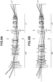
- Figs. 9A and 9B are lens cross sectional views at a wide-angle end and a telephoto end, respectively, when the converter device according to the first embodiment is attached to the interchangeable lens B.
- Figs. 10A and 10B illustrate aberration diagrams at the wide-angle end and the telephoto end, respectively, when the converter device according to the first embodiment is attached to the interchangeable lens B.
- Fig. 11 is a cross sectional view of a converter device according to a second embodiment.
- Fig. 12 illustrates aberration diagrams of only the converter device according to the second embodiment.
- Figs. 13A and 13B are lens cross sectional views at a wide-angle end and a telephoto end, respectively, when the converter device according to the second embodiment is attached to the interchangeable lens A.
- Figs. 14A and 14B illustrate aberration diagrams at the wide-angle end and the telephoto end, respectively, when the converter device according to the second embodiment is attached to the interchangeable lens A.
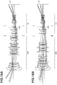
- Figs. 15A and 15B are lens cross sectional views at a wide-angle end and a telephoto end, respectively, when the converter device according to the second embodiment is attached to the interchangeable lens B.
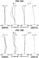
- Figs. 16A and 16B illustrate aberration diagrams at the wide-angle end and the telephoto end, respectively, when the converter device according to the second embodiment is attached to the interchangeable lens B.
- Fig. 17 is a cross sectional view of a converter device according to a third embodiment.
- Fig. 18 illustrates aberration diagrams of only the converter device according to the third embodiment.
- Figs. 19A and 19B are lens cross sectional views at a wide-angle end and a telephoto end, respectively, when the converter device according to the third embodiment is attached to the interchangeable lens A.
- Figs. 20A and 20B illustrate aberration diagrams at the wide-angle end and the telephoto end, respectively, when the converter device according to the third embodiment is attached to the interchangeable lens A.
- Figs. 21A and 21B are lens cross sectional views at a wide-angle end and a telephoto end, respectively, when the converter device according to the third embodiment is attached to the interchangeable lens B.
- Figs. 22A and 22B illustrate aberration diagrams at the wide-angle end and the telephoto end, respectively, when the converter device according to the third embodiment is attached to the interchangeable lens B.
- Fig. 23 is a cross sectional view of a converter device according to a fourth embodiment.
- Fig. 24 illustrates aberration diagrams of only the converter device according to the fourth embodiment.
- Figs. 25A and 25B are lens cross sectional views at a wide-angle end and a telephoto end, respectively, when the converter device according to the fourth embodiment is attached to the interchangeable lens A.
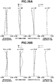
- Figs. 26A and 26B illustrate aberration diagrams at the wide-angle end and the telephoto end, respectively, when the converter device according to the fourth embodiment is attached to the interchangeable lens A.
- Figs. 27A and 27B are lens cross sectional views at a wide-angle end and a telephoto end, respectively, when the converter device according to the fourth embodiment is attached to the interchangeable lens B.
- Figs. 28A and 28B illustrate aberration diagrams at the wide-angle end and the telephoto end, respectively, when the converter device according to the fourth embodiment is attached to the interchangeable lens B.
- the left side is the object side (front side), and the right side is the image side (rear side).
- IP denotes an image plane.
- the image plane IP corresponds to a solid-state image capturing element (photoelectric conversion element) such as a charge coupled device (CCD) sensor or a complementary metal oxide semiconductor (CMOS) sensor for receiving an image formed by the reimaging optical system.
- the image plane IP corresponds to a film plane.
- the imaging plane of the secondary image formed by the reimaging optical system is located on the image plane IP.
- Fno denotes an F-number
- spherical aberrations with respect to a d line wavelength 587.6 nm
- a g line wavelength 435.8 nm
- S denotes a sagittal image plane
- M denotes a meridional image plane
- the distortion diagrams each indicate a d line
- the chromatic aberration diagrams each illustrate a chromatic aberration with respect to a g line.
- the sign of ⁇ denotes an imaging half angle of view.
- the imaging magnification of the reimaging optical system is represented as ⁇ c
- the distance on the optical axis from the lens surface nearest to the object side in the reimaging optical system to the primary image is represented as Objc
- the distance on the optical axis from the lens surface nearest to the object side in the reimaging optical system to the secondary image is represented as Tdc
- the reimaging optical system of each embodiment satisfies the following conditional expressions. ⁇ 5.00 ⁇ ⁇ c ⁇ ⁇ 0.55 ⁇ 0.20 ⁇ Objc / Tdc ⁇ 0.50
- the sign of Objc is positive when the primary image is located on the image side more than the lens surface nearest to the object side in the reimaging optical system.
- the imaging magnification becomes a negative value because the primary image is reversed by the reimaging optical system, and reimaged on the imaging plane as the secondary image.
- an off-axis ray is vignetted when the converter device is attached therebetween.
- increasing the effective diameter of the interchangeable lens in advance to avoid the off-axis ray from being vignetted is not desirable because this leads to increase in size of the interchangeable lens.
- the reimaging optical system is configured so that the imaging magnification of the reimaging optical system becomes high. This avoids the off-axis ray from being vignetted when the converter device is attached without leading to increase in the size of the interchangeable lens.
- the converter device according to an embodiment of the present invention also achieves increase in imaging magnifications and expansion of imaging functions.
- the imaging magnification ⁇ c of the reimaging optical system becomes high and exceeds the lower limit in the conditional expression (1), it becomes difficult to sufficiently correct the axial chromatic aberration generated in the reimaging optical system, which is not desirable.
- the imaging magnification ⁇ c of the reimaging optical system becomes low and exceeds the upper limit in the conditional expression (1), vignetting of marginal rays occurs, which is not desirable. Also, this leads to increase in the size of the interchangeable lens to avoid vignetting of the marginal rays, which is not desirable.
- the conditional expression (2) is a conditional expression that defines the ratio between the distance Objc on the optical axis from the lens surface nearest to the object side in the reimaging optical system to the primary image, and the distance Tdc on the optical axis from the lens surface nearest to the object side in the reimaging optical system to the secondary image.
- the ratio exceeds the lower limit of the conditional expression (2), and the primary image is located at a position apart from the lens surface nearest to the object side in the reimaging optical system to the object side, the entire length of the converter device increases, which is not desirable.
- the angle between the optical axis and the principal ray of the most off axis passing through the surface nearest to the object side in the reimaging optical system to form the image of the maximum image height on a positive side is represented as ⁇ '
- the angle between the optical axis and the principal ray of the most off axis passing through the surface nearest to the image side in the reimaging optical system to form the image of the maximum image height on the positive side is represented as ⁇ ".
- the positive side denotes the area on the upper side than the optical axis of the reimaging optical system when the ray incident in the reimaging optical system is imaged on the imaging plane in a case where the subject is arranged on the left side of the imaging optical system and the image plane exists on the right side of the reimaging optical system.
- the angle of the principal ray inclined in the clockwise direction with respect to the optical axis is represented with a positive sign
- the angle of the principal ray inclined in the counterclockwise direction with respect to the optical axis is represented with a negative sign.
- the ray indicated by the arrow A corresponds to the principal ray of the most off axis passing through the surface nearest to the object side in the reimaging optical system to form the image of the maximum image height on the positive side.
- the ray indicated by the arrow B corresponds to the principal ray of the most off axis passing through the surface nearest to the image side in the reimaging optical system to form the image of the maximum image height on the positive side.
- the angle ⁇ ' is represented with the positive sign
- angle ⁇ " is represented with the negative sign.
- the converter device needs to reverse the light flux having passed through the primary imaging plane (primary image plane (PIP)) to reimage the reversed light flux on the secondary imaging plane, so that the entire length of the reimaging optical system is likely to increase. To shorten the entire length of the reimaging optical system, it is important to cause the primary imaging plane (PIP) to come close to the secondary imaging plane.
- primary imaging plane primary image plane
- the conditional expression (3) is a conditional expression defining the angle ⁇ ' between the optical axis and the principal ray of the most off axis passing through the surface nearest to the object side in the reimaging optical system to form the image of the maximum image height on the positive side.
- the conditional expression (3) is an expression that sets the incident angle of the principal ray to increase the overlapped range of both angles. When the incident angle exceeds the upper limit or the lower limit of the conditional expression (3), the marginal area of the image becomes dark, which is not desirable.
- the conditional expression (4) is a conditional expression defining the angle ⁇ " between the optical axis and the principal ray of the most off axis passing through the surface nearest to the image side in the reimaging optical system to form the image of the maximum image height on the positive side.
- the reimaging optical system needs to reverse the primary image to image the reversed primary image as the secondary image.
- the angle of the light flux to be emitted on the image side be large as much as possible, downsizing of the reimaging optical system and improvement of performance of the reimaging optical system can be achieved at the same time.
- the incident angle of the ray to the image capturing element is too large, shading and coloring occur in the marginal area of the image.
- the conditional expression (5) is a conditional expression that defines the angle ⁇ ' and the angle ⁇ ".
- the conditional expression (5) is a conditional expression that defines the angle ⁇ ' and the angle ⁇ ".
- Hmax the maximum image height in the state where the interchangeable lens is attached via the converter device
- Ear the effective diameter of the lens surface nearest to the image side of the converter device
- the effective diameter Ear of the lens surface nearest to the image side of the converter device becomes small with respect to the maximum image height and exceeds the lower limit of the conditional expression (6), the incident angle to the image plane of an off-axis ray becomes large, so that shading and coloring are liable to occur, which is not desirable.
- the effective diameter Ear of the lens surface nearest to the image side of the converter device becomes large with respect to the maximum image height and exceeds the upper limit of the conditional expression (6), the diameter of the converter device increases in size, which is not desirable.
- the converter device according to an embodiment of the present invention When the converter device according to an embodiment of the present invention is attached to an image capturing apparatus, a subject image is reversed as compared with the case where no converter device is attached.
- the reversed image formed by reversing the image formed by the reimaging optical system be displayed on a display unit in an image capturing apparatus that has the display unit including a liquid crystal display and the like for displaying a captured image and an electronic view finder including an eyepiece lens for observing the image displayed on the display unit.
- the lens surface nearest to the object side in the reimaging optical system exists at a position separated by 15 mm to the object side from the imaging plane of the primary image formed by the imaging optical system.
- the reimaging optical system of the first embodiment is an optical system with an imaging magnification of -1.40 times and an F-number of 4.00.
- the lens surface nearest to the object side in the reimaging optical system exists at a position separated by 30 mm to the object side from the imaging plane of the primary image formed by the imaging optical system.
- the reimaging optical system of the second embodiment is an optical system with an imaging magnification of -2.00 times and an F-number of 5.66.
- the lens surface nearest to the object side in the reimaging optical system exists at a position separated by 38 mm to the object side from the imaging plane of the primary image formed by the imaging optical system.
- the reimaging optical system of the third embodiment is an optical system with an imaging magnification of -1.00 times and an F-number of 2.80.
- the converter device according to the third embodiment has an imaging magnification of -1.00 times, and has no function to extend the focal length of the interchangeable lens.
- the converter device according to the third embodiment has an image stabilization lens unit IS as illustrated in Fig. 17 and is capable of performing an image shake correction.
- the converter device may be configured to perform wobbling motion in autofocus of a contrast system (contrast autofocus (AF)) by finely driving the image stabilization lens unit IS in the optical axis direction.
- the wobbling motion is a motion performed to determine in which direction of the infinity side and the closer side the focusing position exists in the contrast AF.
- the lens surface nearest to the object side of the reimaging optical system exists at a position separated by 6 mm to the image side from the imaging plane of the primary image formed by the imaging optical system.
- the reimaging optical system of the fourth embodiment is an optical system with an imaging magnification of -1.40 times and an F-number of 4.00.
- lens data of the optical systems included in the converter devices according to the first to fourth embodiments of the present invention, and lens data of the imaging optical system of each of the interchangeable lenses A and B to which the converter device according to an embodiment of the present invention is attached will be illustrated.
- i denotes an order of the optical surface from the object side.
- ri denotes a curvature radius of an optical surface of i-th (i-th surface)
- di denotes a distance between an i-th surface and an i + 1-th surface
- ndi and vdi denotes a refractive index and an Abbe number of the material of the optical member A of i-th with respect to a d line, respectively.
- r is a paraxial curvature radius.
- e-Z denotes "10 -Z ".
- back focus indicates, by an air-converted length, a distance from the surface nearest to the image side to the image plane in the imaging optical system or the optical system included in the converter device.
Landscapes
- Physics & Mathematics (AREA)
- General Physics & Mathematics (AREA)
- Optics & Photonics (AREA)
- Engineering & Computer Science (AREA)
- Multimedia (AREA)
- Signal Processing (AREA)
- Lenses (AREA)
Abstract
Description
- The present invention relates to an image capturing apparatus such as a single-lens reflex camera, and a converter device that is attached between an interchangeable lens, which is attachable to and detachable from the image capturing apparatus, and the image capturing apparatus.
- In the field of image capturing systems including image capturing apparatuses (e.g., single-lens reflex cameras or mirrorless cameras) and interchangeable lenses that are attachable to and detachable from the image capturing apparatuses, converter devices that are attached between an image capturing apparatus and an interchangeable lens are known. Such image capturing systems expand imaging functions and increases imaging magnifications by using the converter devices.
Japanese Patent Application Laid-Open No. 2015-102734 - In the teleconverter discussed in
Japanese Patent Application Laid-Open No. 2015-102734 - The teleconverter discussed in
Japanese Patent Application Laid-Open No. 2015-102734 - On the other hand, when the teleconverter is attached to an imaging lens having a relatively short back focus, the attachment position of the teleconverter is moved toward the image side, as compared with the case where the teleconverter is attached to the imaging lens having a long back focus. In this case, the lens component having negative refractive power is arranged at a position where the height of an axial ray is low, which makes it difficult to sufficiently extend the focal length of the imaging lens.
- The back focus typically tends to be short in interchangeable lenses having wide field angles, so that it is often difficult to extend the focal lengths of those interchangeable lenses by attaching converter device between such an interchangeable lens and a camera body.
- Further, mirrorless cameras have no quick return mirrors, so that the back focus to be required is shorter as compared with single-lens reflex cameras. Consequently, interchangeable lenses for mirrorless cameras can be readily downsized as compared with interchangeable lenses for single-lens cameras. Meanwhile, from the viewpoint of space, in the interchangeable lenses for mirrorless cameras, it is often difficult to extend the focal length of those interchangeable lenses by attaching a converter device.
- As such, conventional converter devices are unsuitable for the interchangeable lenses having relatively wide field angles or the interchangeable lenses for mirrorless cameras. In addition, the conventional converter devices have difficulty sufficiently extending the focal lengths of those interchangeable lenses.
- The present invention is directed to a converter device that can be attached between an interchangeable lens and a camera body, and that has high optical performance.
- According to a first aspect of the present invention, there is provided a converter device as specified in claims 1 to 4. According to a second aspect of the present invention, there is provided an image capturing apparatus as specified in claims 5 to 7.
- Further features of the present invention will become apparent from the following description of embodiments with reference to the attached drawings.
-
-
Figs. 1A and 1B are cross sectional views of an interchangeable lens A at a wide-angle end and a telephoto end, respectively. -
Figs. 2A and 2B illustrate aberration diagrams of the interchangeable lens A at the wide-angle end and the telephoto end, respectively. -
Figs. 3A and 3B are cross sectional views of an interchangeable lens B at a wide-angle end and a telephoto end, respectively. -
Figs. 4A and 4B illustrate aberration diagrams of the interchangeable lens B at the wide-angle end and the telephoto end, respectively. -
Fig. 5 is a cross sectional view of a converter device according to a first embodiment. -
Fig. 6 illustrates aberration diagrams of the converter device according to the first embodiment. -
Figs. 7A and 7B are cross sectional views at a wide-angle end and a telephoto end, respectively, when the converter device according to the first embodiment is attached to the interchangeable lens A. -
Figs. 8A and 8B illustrate aberration diagrams at the wide-angle end and the telephoto end, respectively, when the converter device according to the first embodiment is attached to the interchangeable lens A. -
Figs. 9A and 9B are cross sectional views at a wide-angle end and a telephoto end, respectively, when the converter device according to the first embodiment is attached to the interchangeable lens B. -
Figs. 10A and 10B illustrate aberration diagrams at the wide-angle end and the telephoto end, respectively, when the converter device according to the first embodiment is attached to the interchangeable lens B. -
Fig. 11 is a cross sectional view of a converter device according to a second embodiment. -
Fig. 12 illustrates aberration diagrams of the converter device according to the second embodiment. -
Figs. 13A and 13B are cross sectional views at a wide-angle end and a telephoto end, respectively, when the converter device according to the second embodiment is attached to the interchangeable lens A. -
Figs. 14A and 14B illustrate aberration diagrams at the wide-angle end and the telephoto end, respectively, when the converter device according to the second embodiment is attached to the interchangeable lens A. -
Figs. 15A and 15B are cross sectional views at a wide-angle end and a telephoto end, respectively, when the converter device according to the second embodiment is attached to the interchangeable lens B. -
Figs. 16A and 16B illustrate aberration diagrams at the wide-angle end and the telephoto end, respectively, when the converter device according to the second embodiment is attached to the interchangeable lens B. -
Fig. 17 is a cross sectional view of a converter device according to a third embodiment. -
Fig. 18 illustrates aberration diagrams of the converter device according to the third embodiment. -
Figs. 19A and 19B are cross sectional views at a wide-angle end and a telephoto end, respectively, when the converter device according to the third embodiment is attached to the interchangeable lens A. -
Figs. 20A and 20B illustrate aberration diagrams at the wide-angle end and the telephoto end, respectively, when the converter device according to the third embodiment is attached to the interchangeable lens A. -
Figs. 21A and 21B are cross sectional views at a wide-angle end and a telephoto end, respectively, when the converter device according to the third embodiment is attached to the interchangeable lens B. -
Figs. 22A and 22B illustrate aberration diagrams at the wide-angle end and the telephoto end, respectively, when the converter device according to the third embodiment is attached to the interchangeable lens B. -
Fig. 23 is a cross sectional view of a converter device according to a fourth embodiment. -
Fig. 24 illustrates aberration diagrams of the converter device according to the fourth embodiment. -
Figs. 25A and 25B are cross sectional views at a wide-angle end and a telephoto end, respectively, when the converter device according to the fourth embodiment is attached to the interchangeable lens A. -
Figs. 26A and 26B illustrate aberration diagrams at the wide-angle end and the telephoto end, respectively, when the converter device according to the fourth embodiment is attached to the interchangeable lens A. -
Figs. 27A and 27B are cross sectional views at a wide-angle end and a telephoto end, respectively, when the converter device according to the fourth embodiment is attached to the interchangeable lens B. -
Figs. 28A and 28B illustrate aberration diagrams at the wide-angle end and the telephoto end, respectively, when the converter device according to the fourth embodiment is attached to the interchangeable lens B. -
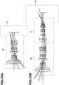
Figs. 29A and 29B are schematic diagrams of an image capturing system when a converter device is detached and attached, respectively. - Hereinafter, converter devices and image capturing apparatuses according to embodiments of the invention will be described in detail based on the accompanying drawings. The converter devices according to the embodiments of the present invention are each attached between an interchangeable lens, which is attachable to and detachable from the image capturing apparatus (camera body), and the camera body.
- The converter devices according to the embodiments of the present invention each have a reimaging optical system (converter lens (CL)) for reimaging a primary image formed by an imaging optical system (master system (MS)) included in the interchangeable lens on an imaging plane to form a secondary image. With this configuration, converter devices that can be used also for an interchangeable lens having a short back focus can be obtained.
-
Japanese Patent Application Laid-Open No. 2004-46022 Japanese Patent Application Laid-Open No. 2002-131637 Japanese Patent Application Laid-Open No. 2004-46022 Japanese Patent Application Laid-Open No. 2002-131637 - On the other hand, the converter devices according to the embodiments of the present invention are applicable to an image capturing system capable of performing an imaging operation with no light in a marginal area being vignetted even in the case where only an interchangeable lens and a camera body are combined. The imaging system is capable of imaging a subject image in the marginal area regardless of presence or absence of the converter device, and is further capable of achieving increase in imaging magnifications and expansion of imaging functions by using the converter device.
- As illustrated in
Fig. 29A , the converter devices according to the embodiments of the present invention can be applied to the system capable of imaging with no light in the marginal area being vignetted in the state where the interchangeable lens is attached to the camera body with no converter device intervening. Further, as illustrated inFig. 29B , the converter device can be attached between the camera body and the interchangeable lens, and a subject image can be imaged on an imaging plane with no light in the marginal area being vignetted also in the state where the converter device is attached therebetween. By configuring the reimaging optical system to reimage the primary image formed by the imaging optical system of the interchangeable lens, the converter device can be downsized. -
Figs. 1A and 1B are each a lens cross sectional view of an optical system of an interchangeable lens A to which the converter device according to an embodiment of the present invention can be attached.Figs. 1A and 1B are lens cross sectional views at a wide-angle end and a telephoto end, respectively.Figs. 2A and 2B illustrate aberration diagrams of the optical system of the interchangeable lens A at the wide-angle end and the telephoto end, respectively. -
Figs. 3A and 3B are each a lens cross sectional view of an optical system of an interchangeable lens B to which the converter device according to an embodiment of the present invention can be attached.Figs. 3A and 3B are lens cross sectional views at a wide-angle end and a telephoto end, respectively.Figs. 4A and 4B illustrate aberration diagrams of the optical system of the interchangeable lens B at the wide-angle end and the telephoto end, respectively. -
Fig. 5 is a cross sectional view of a converter device according to a first embodiment.Fig. 6 illustrates aberration diagrams of only the converter device according to the first embodiment. Herein, the aberration diagrams of only the converter device denote the aberration diagrams in the case where an image is formed by only the converter device with respect to a subject of an infinite object. The same applies to the following aberration diagrams. -
Figs. 7A and 7B are lens cross sectional views at a wide-angle end and a telephoto end, respectively, when the converter device according to the first embodiment is attached to the interchangeable lens A.Figs. 8A and 8B illustrate aberration diagrams at the wide-angle end and the telephoto end, respectively, when the converter device according to the first embodiment is attached to the interchangeable lens A.Figs. 9A and 9B are lens cross sectional views at a wide-angle end and a telephoto end, respectively, when the converter device according to the first embodiment is attached to the interchangeable lens B.Figs. 10A and 10B illustrate aberration diagrams at the wide-angle end and the telephoto end, respectively, when the converter device according to the first embodiment is attached to the interchangeable lens B. -
Fig. 11 is a cross sectional view of a converter device according to a second embodiment.Fig. 12 illustrates aberration diagrams of only the converter device according to the second embodiment.Figs. 13A and 13B are lens cross sectional views at a wide-angle end and a telephoto end, respectively, when the converter device according to the second embodiment is attached to the interchangeable lens A.Figs. 14A and 14B illustrate aberration diagrams at the wide-angle end and the telephoto end, respectively, when the converter device according to the second embodiment is attached to the interchangeable lens A.Figs. 15A and 15B are lens cross sectional views at a wide-angle end and a telephoto end, respectively, when the converter device according to the second embodiment is attached to the interchangeable lens B.Figs. 16A and 16B illustrate aberration diagrams at the wide-angle end and the telephoto end, respectively, when the converter device according to the second embodiment is attached to the interchangeable lens B. -
Fig. 17 is a cross sectional view of a converter device according to a third embodiment.Fig. 18 illustrates aberration diagrams of only the converter device according to the third embodiment.Figs. 19A and 19B are lens cross sectional views at a wide-angle end and a telephoto end, respectively, when the converter device according to the third embodiment is attached to the interchangeable lens A.Figs. 20A and 20B illustrate aberration diagrams at the wide-angle end and the telephoto end, respectively, when the converter device according to the third embodiment is attached to the interchangeable lens A.Figs. 21A and 21B are lens cross sectional views at a wide-angle end and a telephoto end, respectively, when the converter device according to the third embodiment is attached to the interchangeable lens B.Figs. 22A and 22B illustrate aberration diagrams at the wide-angle end and the telephoto end, respectively, when the converter device according to the third embodiment is attached to the interchangeable lens B. -
Fig. 23 is a cross sectional view of a converter device according to a fourth embodiment.Fig. 24 illustrates aberration diagrams of only the converter device according to the fourth embodiment.Figs. 25A and 25B are lens cross sectional views at a wide-angle end and a telephoto end, respectively, when the converter device according to the fourth embodiment is attached to the interchangeable lens A.Figs. 26A and 26B illustrate aberration diagrams at the wide-angle end and the telephoto end, respectively, when the converter device according to the fourth embodiment is attached to the interchangeable lens A.Figs. 27A and 27B are lens cross sectional views at a wide-angle end and a telephoto end, respectively, when the converter device according to the fourth embodiment is attached to the interchangeable lens B.Figs. 28A and 28B illustrate aberration diagrams at the wide-angle end and the telephoto end, respectively, when the converter device according to the fourth embodiment is attached to the interchangeable lens B. - In each lens cross sectional view, the left side is the object side (front side), and the right side is the image side (rear side). IP denotes an image plane. When the converter device according to an embodiment of the present invention is used for a video camera or a digital camera, the image plane IP corresponds to a solid-state image capturing element (photoelectric conversion element) such as a charge coupled device (CCD) sensor or a complementary metal oxide semiconductor (CMOS) sensor for receiving an image formed by the reimaging optical system. When the converter device according to an embodiment of the present invention is used for a silver-halide film camera, the image plane IP corresponds to a film plane. The imaging plane of the secondary image formed by the reimaging optical system is located on the image plane IP.
- In the spherical aberration diagrams, Fno denotes an F-number, and spherical aberrations with respect to a d line (wavelength 587.6 nm) and a g line (wavelength 435.8 nm) are indicated. In the astigmatism diagrams, S denotes a sagittal image plane, and M denotes a meridional image plane. The distortion diagrams each indicate a d line. The chromatic aberration diagrams each illustrate a chromatic aberration with respect to a g line. The sign of ω denotes an imaging half angle of view.
- Given that the imaging magnification of the reimaging optical system is represented as βc, the distance on the optical axis from the lens surface nearest to the object side in the reimaging optical system to the primary image is represented as Objc, and the distance on the optical axis from the lens surface nearest to the object side in the reimaging optical system to the secondary image is represented as Tdc, the reimaging optical system of each embodiment satisfies the following conditional expressions.


- The sign of Objc is positive when the primary image is located on the image side more than the lens surface nearest to the object side in the reimaging optical system.
- The imaging magnification becomes a negative value because the primary image is reversed by the reimaging optical system, and reimaged on the imaging plane as the secondary image. In the system in which the converter device is attached between the interchangeable lens and the camera body, when the magnification of the converter device is too low, an off-axis ray is vignetted when the converter device is attached therebetween. Further, increasing the effective diameter of the interchangeable lens in advance to avoid the off-axis ray from being vignetted is not desirable because this leads to increase in size of the interchangeable lens.
- In the converter device according to an embodiment of the present invention, the reimaging optical system is configured so that the imaging magnification of the reimaging optical system becomes high. This avoids the off-axis ray from being vignetted when the converter device is attached without leading to increase in the size of the interchangeable lens. The converter device according to an embodiment of the present invention also achieves increase in imaging magnifications and expansion of imaging functions.
- When the imaging magnification βc of the reimaging optical system becomes high and exceeds the lower limit in the conditional expression (1), it becomes difficult to sufficiently correct the axial chromatic aberration generated in the reimaging optical system, which is not desirable. When the imaging magnification βc of the reimaging optical system becomes low and exceeds the upper limit in the conditional expression (1), vignetting of marginal rays occurs, which is not desirable. Also, this leads to increase in the size of the interchangeable lens to avoid vignetting of the marginal rays, which is not desirable.
- The conditional expression (2) is a conditional expression that defines the ratio between the distance Objc on the optical axis from the lens surface nearest to the object side in the reimaging optical system to the primary image, and the distance Tdc on the optical axis from the lens surface nearest to the object side in the reimaging optical system to the secondary image. When the ratio exceeds the lower limit of the conditional expression (2), and the primary image is located at a position apart from the lens surface nearest to the object side in the reimaging optical system to the object side, the entire length of the converter device increases, which is not desirable. When the ratio exceeds the upper limit of the conditional expression (2), and the primary image is located at a position apart from the lens surface nearest to the object side in the reimaging optical system to the image side, the refractive power of the reimaging optical system becomes too strong and axial chromatic aberration occurs much, which is not desirable.
- As described above, elements are appropriately set to satisfy the conditional expressions (1) and (2) in each embodiment. This makes it possible to provide the converter device that can be used also for the interchangeable lens having a short back focus, and that has high optical performance.
- In each embodiment, it is desirable that the numerical ranges of the conditional expressions (1) and (2) be set as described below.


- It is more desirable that the numerical ranges of the conditional expressions (1) and (2) be set as described below.


- It is further more desirable that one or more of the following conditional expressions be satisfied in each embodiment.


- Herein, the angle between the optical axis and the principal ray of the most off axis passing through the surface nearest to the object side in the reimaging optical system to form the image of the maximum image height on a positive side is represented as α', and the angle between the optical axis and the principal ray of the most off axis passing through the surface nearest to the image side in the reimaging optical system to form the image of the maximum image height on the positive side is represented as α".
- As illustrated in
Figs. 7A and 7B , the positive side denotes the area on the upper side than the optical axis of the reimaging optical system when the ray incident in the reimaging optical system is imaged on the imaging plane in a case where the subject is arranged on the left side of the imaging optical system and the image plane exists on the right side of the reimaging optical system. In this case, the angle of the principal ray inclined in the clockwise direction with respect to the optical axis is represented with a positive sign, and the angle of the principal ray inclined in the counterclockwise direction with respect to the optical axis is represented with a negative sign. When description is made with reference toFig. 7A as an example, the ray indicated by the arrow A corresponds to the principal ray of the most off axis passing through the surface nearest to the object side in the reimaging optical system to form the image of the maximum image height on the positive side. Further, the ray indicated by the arrow B corresponds to the principal ray of the most off axis passing through the surface nearest to the image side in the reimaging optical system to form the image of the maximum image height on the positive side. In the case ofFig. 7A , the angle α' is represented with the positive sign, and angle α" is represented with the negative sign. - The converter device according to an embodiment of the present invention needs to reverse the light flux having passed through the primary imaging plane (primary image plane (PIP)) to reimage the reversed light flux on the secondary imaging plane, so that the entire length of the reimaging optical system is likely to increase. To shorten the entire length of the reimaging optical system, it is important to cause the primary imaging plane (PIP) to come close to the secondary imaging plane.
- The conditional expression (3) is a conditional expression defining the angle α' between the optical axis and the principal ray of the most off axis passing through the surface nearest to the object side in the reimaging optical system to form the image of the maximum image height on the positive side. To secure sufficient marginal illumination of the synthesis system of the interchangeable lens and the reimaging optical system, it is necessary to match pupils of respective optical systems to each other. In other words, it is desirable to increase the range where the range of the angle of the light flux incident from the object side in the reimaging optical system and the range of the angle of the light flux emitted to the image side from the interchangeable lens are overlapped. The conditional expression (3) is an expression that sets the incident angle of the principal ray to increase the overlapped range of both angles. When the incident angle exceeds the upper limit or the lower limit of the conditional expression (3), the marginal area of the image becomes dark, which is not desirable.
- The conditional expression (4) is a conditional expression defining the angle α" between the optical axis and the principal ray of the most off axis passing through the surface nearest to the image side in the reimaging optical system to form the image of the maximum image height on the positive side. the reimaging optical system needs to reverse the primary image to image the reversed primary image as the secondary image. Herein, by making the angle of the light flux to be emitted on the image side be large as much as possible, downsizing of the reimaging optical system and improvement of performance of the reimaging optical system can be achieved at the same time. On the other hand, when the incident angle of the ray to the image capturing element is too large, shading and coloring occur in the marginal area of the image.
- When the angle α" exceeds the lower limit of the conditional expression (4) and becomes too large, shading and coloring occur, which is not desirable. When the angle α" exceeds the upper limit of the conditional expression (4) and become too small, the entire length of the converter device increases, which is not desirable.
- The conditional expression (5) is a conditional expression that defines the angle α' and the angle α". When the sum of the angle α' and the angle α" exceeds the upper limit or the lower limit of the conditional expression (5), it becomes difficult to suppress shading and the like while securing sufficient marginal illumination of the synthesis system of the interchangeable lens and the converter device, and downsizing the converter device, which is not desirable.
- It is desirable that the numerical ranges of the conditional expressions (3) to (5) be set as described below.


- It is more desirable that the numerical ranges of the conditional expressions (3) to (5) be set as described below.



- Furthermore, when the converter device according to an embodiment of the present invention is applied to an image capturing apparatus having an imaging plane for the secondary image formed by the reimaging optical system, it is desirable that the following conditional expression be satisfied.

- Herein, the maximum image height in the state where the interchangeable lens is attached via the converter device is represented as Hmax, and the effective diameter of the lens surface nearest to the image side of the converter device is represented as Ear.
- When the effective diameter Ear of the lens surface nearest to the image side of the converter device becomes small with respect to the maximum image height and exceeds the lower limit of the conditional expression (6), the incident angle to the image plane of an off-axis ray becomes large, so that shading and coloring are liable to occur, which is not desirable. When the effective diameter Ear of the lens surface nearest to the image side of the converter device becomes large with respect to the maximum image height and exceeds the upper limit of the conditional expression (6), the diameter of the converter device increases in size, which is not desirable.
- It is desirable that the numerical range of the conditional expression (6) be set as described below.

- It is more desirable that the numerical range of the conditional expression (6) be set as described below.

- When the converter device according to an embodiment of the present invention is attached to an image capturing apparatus, a subject image is reversed as compared with the case where no converter device is attached. Thus, it is desirable that the reversed image formed by reversing the image formed by the reimaging optical system be displayed on a display unit in an image capturing apparatus that has the display unit including a liquid crystal display and the like for displaying a captured image and an electronic view finder including an eyepiece lens for observing the image displayed on the display unit. with this configuration, an erected image can be observed through the electronic view finder even when the converter device according to an embodiment of the present invention is attached to the image capturing apparatus.
- Next, configurations of converter devices according to embodiments of the present invention will be described. In a reimaging optical system included in a converter device according to a first embodiment, the lens surface nearest to the object side in the reimaging optical system exists at a position separated by 15 mm to the object side from the imaging plane of the primary image formed by the imaging optical system. The reimaging optical system of the first embodiment is an optical system with an imaging magnification of -1.40 times and an F-number of 4.00.
- In a reimaging optical system included in a converter device according to a second embodiment, the lens surface nearest to the object side in the reimaging optical system exists at a position separated by 30 mm to the object side from the imaging plane of the primary image formed by the imaging optical system. The reimaging optical system of the second embodiment is an optical system with an imaging magnification of -2.00 times and an F-number of 5.66.
- In a reimaging optical system included in a converter device according to a third embodiment, the lens surface nearest to the object side in the reimaging optical system exists at a position separated by 38 mm to the object side from the imaging plane of the primary image formed by the imaging optical system. The reimaging optical system of the third embodiment is an optical system with an imaging magnification of -1.00 times and an F-number of 2.80. The converter device according to the third embodiment has an imaging magnification of -1.00 times, and has no function to extend the focal length of the interchangeable lens. However, the converter device according to the third embodiment has an image stabilization lens unit IS as illustrated in
Fig. 17 and is capable of performing an image shake correction. By moving the image stabilization lens unit IS in the direction having a component of a vertical direction to the optical axis, an image shake correction function can be added. Further, the converter device may be configured to perform wobbling motion in autofocus of a contrast system (contrast autofocus (AF)) by finely driving the image stabilization lens unit IS in the optical axis direction. The wobbling motion is a motion performed to determine in which direction of the infinity side and the closer side the focusing position exists in the contrast AF. - In a reimaging optical system included in a converter device according to a fourth embodiment, the lens surface nearest to the object side of the reimaging optical system exists at a position separated by 6 mm to the image side from the imaging plane of the primary image formed by the imaging optical system. The reimaging optical system of the fourth embodiment is an optical system with an imaging magnification of -1.40 times and an F-number of 4.00.
- Next, lens data of the optical systems included in the converter devices according to the first to fourth embodiments of the present invention, and lens data of the imaging optical system of each of the interchangeable lenses A and B to which the converter device according to an embodiment of the present invention is attached will be illustrated. In each lens data, i denotes an order of the optical surface from the object side. Thus, ri denotes a curvature radius of an optical surface of i-th (i-th surface), di denotes a distance between an i-th surface and an i + 1-th surface, and ndi and vdi denotes a refractive index and an Abbe number of the material of the optical member A of i-th with respect to a d line, respectively.
- Further, given that K denotes an eccentricity, A4, A6, A8, A10, A12, A14, and A16 denote aspheric coefficients, and a displacement in the optical axis direction at the position of the height h from the optical axis is denoted by x based on a surface vertex, an aspheric shape is expressed as follows: x = (h2/r) / [ 1 + [ 1 - (1 + K) (h/r) 2]1/2] + A4h4 + A6h6 + A8h8 + A10h10 + A12h12 + A14h14 + A16h16. In this regard, r is a paraxial curvature radius. Furthermore, the expression of "e-Z" denotes "10-Z".
- In each embodiment, back focus (BF) indicates, by an air-converted length, a distance from the surface nearest to the image side to the image plane in the imaging optical system or the optical system included in the converter device. Correspondences of the above conditional expressions in each numerical embodiment will be illustrated in Table 1.
-
Unit mm Surface Data Surface Number r d nd vd Effective Diameter (ea) 1 204.560 2.10 1.84666 23.9 68.66 2 72.156 7.40 1.77250 49.6 64.50 3 333.009 0.15 63.84 4 56.551 6.70 1.77250 49.6 59.01 5 147.768 (variable) 57.87 6* 107.703 1.60 1.88300 40.8 33.53 7 16.578 7.87 24.69 8 -46.474 1.15 1.59522 67.7 23.67 9 21.417 4.45 1.88300 40.8 21.26 10 67.901 1.27 19.98 11 129.834 3.48 1.59270 35.3 20.65 12 -49.739 1.61 21.37 13 -23.347 1.15 1.72916 54.7 21.43 14 404.189 2.69 1.84666 23.9 23.86 15 -57.801 (Variable) 24.55 16 ∞ 1.90 (Variable) 17(Stop) ∞ 0.00 26.94 18 27.563 1.45 1.88300 40.8 30.03 19 21.253 11.00 1.49700 81.5 29.21 20 -64.876 0.20 29.58 21 43.054 2.70 1.58313 59.4 29.26 22* 63.670 4.61 28.62 23 -44.565 1.40 1.72047 34.7 28.59 24 -153.891 (Variable) 29.25 25 31.112 7.13 1.43875 94.9 30.54 26 -203.991 0.20 30.08 27 47.466 5.85 1.49700 81.5 30.47 28 -71.666 1.96 30.22 29* -205.992 2.10 1.85006 40.2 28.71 30* 88.343 2.63 27.92 31 -442.074 1.40 1.83400 37.2 28.02 32 61.478 5.17 1.51633 64.1 28.80 33 -61.478 29.46 -
- K = 0.00000e+000 A 4 = 7.12736e-006 A6 = -9.11631e-009 A8 = 2.35269e-011 A10 = -5.05824e-014 A12 = 7.73415e-017 22nd Surface
- K = 0.00000e+000 A4 = 5.39187e-006 A6 = 5.52428e-009 A8 = -8.87533e-012 A10 = 1.15050e-013 A12 = -9.43064e-017 29th Surface
- K = 0.00000e+000 A4 = 2.73309e-005 A6 = -1.56548e-007 A8 = 3.98764e-010 A10 = -7.46700e-013 A12 = 6.95925e-016 30th Surface
- K = 0.00000e+000 A4 = 4.43162e-005 A6 = -1.34466e-007 A8 = 3.25418e-010 A10 = -4.48417e-013 A12 = 2.53228e-016 Various Data
-
Unit mm Surface Data Surface Number r d nd vd Effective Diameter (ea) 1* ∞ 2.80 1.76385 48.5 55.22 2* 19.710 10.06 41.37 3* ∞ 2.50 1.85135 40.1 39.75 4* 88.425 8.02 33.18 5 -36.469 1.40 1.59282 68.6 32.90 6 175.507 0.15 34.08 7 72.176 5.58 1.90366 31.3 34.70 8 -95.327 (Variable) 34.66 9 ∞ 1.41 (Variable) 10 99.317 2.66 1.80610 33.3 28.75 11 -213.620 0.15 28.93 12 51.098 1.25 1.84666 23.8 29.43 13 23.542 6.87 1.57501 41.5 28.71 14 261.531 (Variable) 28.83 15 61.498 1.25 1.84666 23.8 29.48 16 38.482 7.24 1.51633 64.1 29.13 17 -53.624 (Variable) 29.12 18(Stop) ∞ 2.97 24.82 19 -55.358 1.00 1.91082 35.3 24.32 20 86.924 1.04 24.50 21 42.754 6.56 1.80809 22.8 25.29 22 -32.152 1.10 1.91082 35.3 25.13 23 91.214 3.03 25.01 24 ∞ (Variable) (Variable) 25 34.148 10.35 1.49700 81.5 25.89 26 -20.776 1.20 1.83481 42.7 25.53 27 -28.692 0.15 26.62 28* 116.832 1.00 1.90366 31.3 26.70 29 26.396 6.61 1.49700 81.5 26.70 30 -130.257 (variable) 27.47 31 ∞ 30.50 -
- K = 0.00000e+000 A4 = 1.16240e-005 A6 = -1.43464e-008 A8 = 1.53911e-011
- A10 = -1.16093e-014 A12 = 2.35255e-017 A14 = -3.41512e-020 A16 = 1.86334e-023
-
- K = -1.28966e+000 A4 = -3.76697e-006 A6 = 4.56307e-010 A8 = 2.74463e-011
- A10 = -7.02319e-013 A12 = 1.59446e-015 A14 = 6.04845e-020 A16 = -1.73466e-021
-
- K = 0.00000e + 000 A4 = -3.64999e-005 A6 = 1.12188e-007 A8 = -1.13740e-010
- A10 = 2.82141e-014 A12 = 2.48495e-016 A14 = -1.09572e-018 A16 = 1.18199e-021
-
- K = 8.77138e+000 A4 = -1.55214e-005 A6 = 1.36095e-007 A8 = -5.52082e-011
- A10 = 4.85385e-014 A12 = 3.55622e-016 A14 = 2.96869e-018 A16 = -1.20548e-020
-
- K = 0.00000e+000 A4 = -9.11671e-006 A6 = 1.48788e-008 A8 = -3.28894e-010
- A10 = 2.34614e-012 A12 = -8.13846e-015 A14 = 6.92483e-018 A16 = 1.77415e-020
-
Unit mm Surface Data Surface Number r d nd vd Effective Diameter (ea) 1 25.000 10.19 1.89286 20.4 31.47 2 -39.769 1.50 1.65412 39.7 30.26 3 16.159 15.08 21.18 4 50.636 3.34 1.89286 20.4 19.94 5 -39.337 1.00 1.51633 64.1 19.69 6 13.689 12.71 17.35 7 34.398 1.00 1.61340 44.3 18.95 8 11.910 7.65 1.59522 67.7 18.43 9 -20.318 0.15 18.32 10 -24.874 2.11 1.59522 67.7 17.63 11 -15.710 1.00 1.76182 26.5 17.40 12 278.545 8.02 17.16 13 87.894 3.21 1.89286 20.4 20.85 14 -37.672 0.15 21.00 15 18.945 3.38 1.95375 32.3 19.79 16 59.982 0.15 18.83 17 17.414 3.47 1.59522 67.7 16.97 18 -188.078 1.00 1.85478 24.8 15.71 19 11.439 2.44 12.82 20 -44.111 1.00 1.85478 24.8 12.82 21 15.174 2.09 1.59522 67.7 12.45 22 57.905 0.15 12.67 23 27.190 6.20 1.76385 48.5 12.93 24* 679.730 13.92 - K = 0.00000e+000 A4 = 4.18517e-005 A6 = 3.55274e-008 A8 = 2.72733e-010 A10 = -2.10007e-012
Focal Length 34.58 F-number 4.00 Image Height 21.64 Total Lens Length 132.02 Object Surface 15.00 BF 45.02 β -1.40 Optical Data Focal Length Lens Structure Length Front-Side Principal Point Position Rear-Side Principal Point Position 34.58 87.00 74.29 -37.98 -
Unit mm Surface Data Surface Number r d nd vd Effective Diameter (ea) 1 189.174 1.30 1.51633 64.1 24.00 2 49.264 7.25 23.64 3 15.000 7.53 1.76385 48.5 24.96 4 38.922 7.74 22.40 5 84.173 1.00 1.51633 64.1 13.40 6 10.856 15.23 11.56 7 -136.064 1.10 1.85478 24.8 14.42 8 13.383 5.82 1.76385 48.5 15.01 9 -18.282 0.15 15.46 10 11.249 3.94 1.89286 20.4 14.36 11 85.062 1.80 13.04 12 27.277 0.53 1.85478 24.8 9.82 13 6.873 0.21 8.60 14 7.821 4.73 1.76385 48.5 8.60 15 -5.753 1.10 1.78472 25.7 7.61 16 17.891 1.27 6.46 17 -8.171 1.00 1.80518 25.4 6.37 18 10.758 3.83 1.76385 48.5 8.01 19 -23.760 0.50 10.20 20 28.844 3.37 1.89286 20.4 12.40 21 -19.640 1.10 1.85478 24.8 12.93 22* -110.866 13.64 - K = 0.00000e+000 A4 = 9.74082e-005 A6 =-7.82151e-008 A8 = 1.00903e-009 A10 = -8.64313e-012
Focal Length 22.89 F-number 5.66 Image Height 21.64 Total Lens Length 110.00 Object Surface 30.00 BF 39.54 β -2.00 Optical Data Focal Length Lens Structure Length Front-Side Principal Point Position Rear-Side Principal Point Position 22.89 70.50 64.34 -29.13 -
Unit mm Surface Data Surface Number r d nd vd Effective Diameter (ea) 1 27.832 4.45 1.48749 37.28 2 37.509 6.32 36.39 3 21.000 8.82 1.89286 20.4 34.85 4 44.223 2.25 31.79 5 38.406 9.78 1.59522 67.7 28.31 6 -22.000 1.30 1.61340 44.3 23.36 7 11.193 13.71 15.35 8 -11.135 1.10 1.80000 29.8 16.40 9 87.814 7.41 1.76385 22.04 10 -17.419 0.15 24.15 11 -309.142 5.82 1.59522 67.7 27.31 12 -23.942 0.15 28.02 13 30.948 4.76 1.89286 20.4 27.81 14 667.437 6.32 27.07 15 24.408 6.13 1.59522 67.7 21.48 16 -31.174 1.10 1.68893 19.98 17 21.401 3.33 17.03 18 -33.943 1.00 1.85478 16.77 19 14.786 5.95 1.59522 16.65 20 -42.452 0.50 17.23 21 28.919 5.29 1.76385 48.5 19.02 22 -23.588 0.15 19.37 23 -25.277 1.10 1.85478 24.8 19.26 24* 103.742 6.06 20.04 25 81.212 2.25 1.89286 20.4 24.49 26 276.579 24.81 - K = 0.00000e+000 A4 = 1.43253e-005 A6 = -1.27277e-008 A8 = -5.58122e-012 A10 = 1.99962e-013
Focal Length 80.63 F-number 2.80 Image Height 21.64 Total Lens Length 145.00 Object Surface 38.00 BF 39.86 β -1.00 Optical Data Focal Length Lens Structure Length Front-Side Principal Point Position Rear-Side Principal Point Position 80.63 105.22 199.27 -121.41 -
Unit mm Surface Data Surface Number r d nd vd Effective Diameter (ea) 1 97.965 9.53 1.84666 23.8 33.28 2 -25.775 2.30 1.48749 70.2 33.32 3 24.990 5.86 2.00069 25.5 27.86 4 231.068 2.00 26.57 5 33.900 0.85 1.68893 31.1 21.98 6 14.723 12.57 19.26 7 -13.674 1.30 1.85478 24.8 14.83 8 21.230 5.47 1.59522 67.7 16.28 9 -21.113 0.15 17.26 10 38.316 4.79 1.76385 48.5 18.08 11 -24.684 0.15 18.06 12 23.196 3.55 1.76385 48.5 15.97 13 -211.118 0.53 14.96 14 -42.515 1.00 1.85478 24.8 14.95 15 20.504 2.27 14.33 16(Stop) ∞ 2.94 14.58 17 -27.272 1.10 1.68893 31.1 15.78 18 38.004 4.70 1.89286 20.4 18.48 19 -32.146 3.74 19.81 20 40.253 5.25 1.76385 48.5 24.79 21 -60.602 13.46 24.92 22 -23.792 2.00 1.85478 24.8 22.49 23* -58.683 23.94 - K = 0.00000e+000 A4 = 1.40449e-005 A6 = -7.92283e-009 A8 = 3.21246e-011 A10 = -1.63685e-013
Focal Length 34.70 F-number 4.00 Image Height 21.64 Total Lens Length 124.00 Object Surface -6.00 BF 38.50 β -1.40 Optical Data Focal Length Lens Structure Length Front-Side Principal Point Position Rear-Side Principal Point Position 34.70 85.53 53.49 -44.79 [Table 1] First Embodiment Second Embodiment Third Embodiment Fourth Embodiment FNO 4.00 5.66 2.80 4.00 Tdc 132.02 110.00 145.00 124.00 Obj c 15.00 30.00 38.00 -6.00 Ear 13.92 13.64 24.81 23.94 Hmax 21.64 21.64 21.64 21.64 (1) βc -1.40 -2.00 -1.00 -1.40 (2) Objc/Tdc 0.11 0.27 0.26 -0.05 (3) α' 3.03 3.00 9.97 2.31 (4) α" -21.87 -23.59 -18.19 -19.63 (5) α' + α" -18.84 -20.59 -8.22 -17.32 (6) Ear/2Hmax 0.32 0.32 0.57 0.55 - While the present invention has been described with reference to embodiments, it is to be understood that the invention is not limited to the disclosed embodiments.
| Zoom Ratio | 2.75 |
| Wide-Angle | Intermediate | Telephoto | |
| Focal Length | 24.70 | 34.91 | 67.88 |
| F-number | 2.91 | 2.91 | 2.91 |
| Half Angle of View | 41.22 | 31.79 | 17.68 |
| Image Height | 21.64 | 21.64 | 21.64 |
| Total Lens Length | 154.68 | 162.21 | 186.04 |
| BF | 38.09 | 46.60 | 63.40 |
| d5 | 2.75 | 11.74 | 30.36 |
| d15 | 13.71 | 7.72 | 0.23 |
| d24 | 8.82 | 4.84 | 0.74 |
| ea16 | 18.54 | 20.67 | 25.63 |
| Unit | Starting Surface | Focal Length | Lens Structure Length | Front-Side Principal Point Position | Rear-Side Principal Point Position |
| 1 | 1 | 106.37 | 16.35 | 1.50 | -7.63 |
| 2 | 6 | -16.39 | 25.26 | 2.87 | -15.39 |
| 3 | 18 | 57.88 | 23.26 | -3.01 | -18.40 |
| 4 | 25 | 46.04 | 26.44 | 1.17 | -18.24 |
| Wide-Angle | Intermediate | Telephoto | |
| Focal Length | 16.48 | 24.01 | 33.95 |
| F-number | 2.91 | 2.91 | 2.91 |
| Half Angle of View | 52.70 | 42.02 | 32.51 |
| Image Height | 21.64 | 21.64 | 21.64 |
| Total Lens Length | 169.81 | 164.72 | 166.09 |
| BF | 38.20 | 38.20 | 38.20 |
| d8 | 28.49 | 11.23 | 0.84 |
| d14 | 4.84 | 9.40 | 4.91 |
| d17 | 2.20 | 7.34 | 11.77 |
| d24 | 9.71 | 2.38 | -0.42 |
| d30 | 0.01 | 9.81 | 24.43 |
| ea9 | 23.11 | 25.85 | 27.85 |
| ea24 | 16.39 | 19.77 | 25.46 |
| Unit | Starting Surface | Focal Length | Lens Structure Length | Front-Side Principal Point Position | Rear-Side Principal Point Position |
| 1 | 1 | -22.34 | 30.51 | 1.56 | -25.50 |
| 2 | 10 | 66.39 | 12.34 | 0.85 | -7.11 |
| 3 | 15 | 68.68 | 8.49 | 3.22 | -2.37 |
| 4 | 19 | -46.49 | 15.71 | 5.24 | -6.29 |
| 5 | 25 | 44.41 | 19.31 | 4.04 | -9.23 |
Claims (7)
- A converter device to be attached between a lens device, which is attachable to and detachable from an image capturing apparatus, and the image capturing apparatus, the converter device comprising a reimaging optical system configured to reimage a primary image formed by the lens device on an image plane as a secondary image,
wherein, given that an imaging magnification of the reimaging optical system is represented as βc, a distance on an optical axis from a lens surface nearest to an object side in the reimaging optical system to the primary image is represented as Objc, and a distance on the optical axis from the lens surface nearest to the object side in the reimaging optical system to the secondary image is represented as Tdc, the following conditional expressions are satisfied:

- The converter device according to claim 1, wherein, given that an angle between the optical axis in the reimaging optical system and a principal ray of a most off axis passing through a surface nearest to the object side in the reimaging optical system to form an image of a maximum image height on a positive side is represented as α', and given that an angle of the principal ray inclined in a clockwise direction with respect to the optical axis is represented with a positive sign, and an angle of the principal ray inclined in a counterclockwise direction with respect to the optical axis is represented with a negative sign, the following conditional expression is satisfied:

- The converter device according to claim 1 or 2, wherein, given that an angle between the optical axis in the reimaging optical system and a principal ray of a most off axis passing through a surface nearest to an image side in the reimaging optical system to form an image of a maximum image height on a positive side is represented as α", and given that an angle of the principal ray inclined in a clockwise direction with respect to the optical axis is represented with a positive sign, and an angle of the principal ray inclined in a counterclockwise direction with respect to the optical axis is represented with a negative sign, the following conditional expression is satisfied:

- The converter device according to any one of claims 1 to 3, wherein, given that an angle between the optical axis in the reimaging optical system and a principal ray of a most off axis passing through a surface nearest to the object side in the reimaging optical system to form an image of a maximum image height on a positive side is represented as α', and an angle between the optical axis in the reimaging optical system and a principal ray of a most off axis passing through a surface nearest to an image side in the reimaging optical system to form an image of a maximum image height on the positive side is represented as α", and given that an angle of the principal ray inclined in a clockwise direction with respect to the optical axis is represented with a positive sign, and an angle of the principal ray inclined in a counterclockwise direction with respect to the optical axis is represented with a negative sign, the following conditional expression is satisfied:

- An image capturing apparatus to which an interchangeable lens is detachably attached via the converter device according to any one of claims 1 to 4, the image capturing apparatus comprising an image capturing element configured to receive a secondary image formed by a reimaging optical system.
- The image capturing apparatus according to claim 5, wherein, given that a maximum image height in a state where the interchangeable lens is attached to the image capturing apparatus via the converter device is represented as Hmax, and an effective diameter of a lens surface nearest to an image side of the converter device is represented as Ear, the following conditional expression is satisfied:

- The image capturing apparatus according to claim 5 or 6, wherein the image capturing apparatus is capable of performing an imaging operation also when the interchangeable lens is attached to the image capturing apparatus with no intermediation of the converter device.
Applications Claiming Priority (1)
| Application Number | Priority Date | Filing Date | Title |
|---|---|---|---|
| JP2015234311A JP6602186B2 (en) | 2015-11-30 | 2015-11-30 | Converter device and imaging device |
Publications (2)
| Publication Number | Publication Date |
|---|---|
| EP3173837A1 true EP3173837A1 (en) | 2017-05-31 |
| EP3173837B1 EP3173837B1 (en) | 2024-03-27 |
Family
ID=57460367
Family Applications (1)
| Application Number | Title | Priority Date | Filing Date |
|---|---|---|---|
| EP16201436.9A Active EP3173837B1 (en) | 2015-11-30 | 2016-11-30 | Converter device and image capturing apparatus |
Country Status (4)
| Country | Link |
|---|---|
| US (1) | US10254508B2 (en) |
| EP (1) | EP3173837B1 (en) |
| JP (1) | JP6602186B2 (en) |
| CN (1) | CN106814440B (en) |
Cited By (1)
| Publication number | Priority date | Publication date | Assignee | Title |
|---|---|---|---|---|
| CN111492294A (en) * | 2017-12-19 | 2020-08-04 | 松下知识产权经营株式会社 | Projection lens system and image projection device |
Families Citing this family (7)
| Publication number | Priority date | Publication date | Assignee | Title |
|---|---|---|---|---|
| JP7159499B2 (en) * | 2019-02-27 | 2022-10-24 | キヤノン株式会社 | converter lens, interchangeable lens, and imaging device |
| JP2020140021A (en) * | 2019-02-27 | 2020-09-03 | キヤノン株式会社 | Converter lenses, interchangeable lenses, and imaging devices |
| CN113296252B (en) * | 2021-05-24 | 2022-10-28 | 江西凤凰光学科技有限公司 | Zoom lens |
| JP7776345B2 (en) | 2022-02-18 | 2025-11-26 | 富士フイルム株式会社 | Zoom lens, projection display device, and imaging device |
| JP7871572B2 (en) * | 2022-03-31 | 2026-06-09 | ソニーグループ株式会社 | Converter lens and imaging device |
| JP7218469B2 (en) * | 2022-07-06 | 2023-02-06 | キヤノン株式会社 | converter lens, interchangeable lens, and imaging device |
| CN115145009B (en) * | 2022-09-02 | 2022-11-22 | 浙江大华技术股份有限公司 | Lens and camera device |
Citations (4)
| Publication number | Priority date | Publication date | Assignee | Title |
|---|---|---|---|---|
| JP2002131637A (en) | 2000-10-30 | 2002-05-09 | Nikon Corp | Relay optics |
| JP2004046022A (en) | 2002-07-16 | 2004-02-12 | Nikon Corp | Relay optical system with anti-vibration function |
| EP2312341A2 (en) * | 2009-10-06 | 2011-04-20 | Canon Kabushiki Kaisha | Rear attachment lens and imaging optical system including the same |
| JP2015102734A (en) | 2013-11-26 | 2015-06-04 | 株式会社ニコン | Rear converter lens, optical device, and method of manufacturing rear converter lens |
Family Cites Families (6)
| Publication number | Priority date | Publication date | Assignee | Title |
|---|---|---|---|---|
| JPS63205626A (en) * | 1987-02-20 | 1988-08-25 | Minolta Camera Co Ltd | Relay lens system |
| FR2785996B1 (en) * | 1998-11-18 | 2001-02-23 | Thomson Csf | OPTICAL CINEMA LENS ADAPTER ON VIDEO CAMERA |
| DE60308191T2 (en) * | 2002-07-22 | 2007-08-23 | Panavision Inc., Woodland Hills | ZOOM WITH ULTRA-HIGH MAGNIFICATION RATIO |
| JP4458324B2 (en) | 2003-04-09 | 2010-04-28 | キヤノン株式会社 | Anamorphic converter |
| US6995920B2 (en) | 2003-04-04 | 2006-02-07 | Canon Kabushiki Kaisha | Anamorphic converter |
| JP5038694B2 (en) | 2006-11-30 | 2012-10-03 | 興和株式会社 | Telephoto device |
-
2015
- 2015-11-30 JP JP2015234311A patent/JP6602186B2/en active Active
-
2016
- 2016-11-23 US US15/360,740 patent/US10254508B2/en active Active
- 2016-11-28 CN CN201611086223.XA patent/CN106814440B/en active Active
- 2016-11-30 EP EP16201436.9A patent/EP3173837B1/en active Active
Patent Citations (4)
| Publication number | Priority date | Publication date | Assignee | Title |
|---|---|---|---|---|
| JP2002131637A (en) | 2000-10-30 | 2002-05-09 | Nikon Corp | Relay optics |
| JP2004046022A (en) | 2002-07-16 | 2004-02-12 | Nikon Corp | Relay optical system with anti-vibration function |
| EP2312341A2 (en) * | 2009-10-06 | 2011-04-20 | Canon Kabushiki Kaisha | Rear attachment lens and imaging optical system including the same |
| JP2015102734A (en) | 2013-11-26 | 2015-06-04 | 株式会社ニコン | Rear converter lens, optical device, and method of manufacturing rear converter lens |
Cited By (1)
| Publication number | Priority date | Publication date | Assignee | Title |
|---|---|---|---|---|
| CN111492294A (en) * | 2017-12-19 | 2020-08-04 | 松下知识产权经营株式会社 | Projection lens system and image projection device |
Also Published As
| Publication number | Publication date |
|---|---|
| EP3173837B1 (en) | 2024-03-27 |
| JP6602186B2 (en) | 2019-11-06 |
| CN106814440A (en) | 2017-06-09 |
| US10254508B2 (en) | 2019-04-09 |
| CN106814440B (en) | 2019-03-01 |
| US20170153414A1 (en) | 2017-06-01 |
| JP2017102227A (en) | 2017-06-08 |
Similar Documents
| Publication | Publication Date | Title |
|---|---|---|
| EP3173837B1 (en) | Converter device and image capturing apparatus | |
| JP5656895B2 (en) | Zoom lens and imaging apparatus having the same | |
| US8456751B2 (en) | Optical system having fisheye zoom lens and optical apparatus having the optical system | |
| US9081170B2 (en) | Zoom lens and image pickup apparatus including the same | |
| US9684155B2 (en) | Optical system and image pickup apparatus including the same | |
| US8284498B2 (en) | Zoom lens and image pickup apparatus having the same | |
| US20140211029A1 (en) | Zoom lens and image pickup apparatus including the same | |
| EP2309308A1 (en) | Optical system and optical device including the same | |
| US8437090B2 (en) | Zoom lens and image pickup apparatus including the same | |
| US8885264B2 (en) | Zoom lens and image pickup apparatus including the same | |
| US8792181B2 (en) | Zoom lens and image pickup apparatus including the same | |
| JP6965039B2 (en) | Converter lens and camera device with it | |
| US10495861B2 (en) | Zoom lens and image pickup apparatus | |
| US20130242171A1 (en) | Zoom lens system, imaging device and camera | |
| JP2013190534A (en) | Zoom lens and image capturing device using the same | |
| US20170090163A1 (en) | Rear convertor lens and imaging apparatus | |
| WO2017169582A1 (en) | Zoom lens and imaging device | |
| CN107272172A (en) | Variable-power optical system and the camera device with the variable-power optical system | |
| JP4909089B2 (en) | Zoom lens and imaging apparatus having the same | |
| CN110709748B (en) | Zoom lens and camera | |
| JP2017116702A (en) | Zoom lens and imaging apparatus including the same | |
| JP5414771B2 (en) | Zoom lens and imaging apparatus having the same | |
| US8988782B2 (en) | Zoom lens and image pickup apparatus including the same | |
| JP2014202840A (en) | Zoom lens and image capturing device having the same | |
| JP6207237B2 (en) | Zoom lens and imaging apparatus having the same |
Legal Events
| Date | Code | Title | Description |
|---|---|---|---|
| PUAI | Public reference made under article 153(3) epc to a published international application that has entered the european phase |
Free format text: ORIGINAL CODE: 0009012 |
|
| STAA | Information on the status of an ep patent application or granted ep patent |
Free format text: STATUS: THE APPLICATION HAS BEEN PUBLISHED |
|
| AK | Designated contracting states |
Kind code of ref document: A1 Designated state(s): AL AT BE BG CH CY CZ DE DK EE ES FI FR GB GR HR HU IE IS IT LI LT LU LV MC MK MT NL NO PL PT RO RS SE SI SK SM TR |
|
| AX | Request for extension of the european patent |
Extension state: BA ME |
|
| STAA | Information on the status of an ep patent application or granted ep patent |
Free format text: STATUS: REQUEST FOR EXAMINATION WAS MADE |
|
| 17P | Request for examination filed |
Effective date: 20171130 |
|
| RBV | Designated contracting states (corrected) |
Designated state(s): AL AT BE BG CH CY CZ DE DK EE ES FI FR GB GR HR HU IE IS IT LI LT LU LV MC MK MT NL NO PL PT RO RS SE SI SK SM TR |
|
| STAA | Information on the status of an ep patent application or granted ep patent |
Free format text: STATUS: EXAMINATION IS IN PROGRESS |
|
| 17Q | First examination report despatched |
Effective date: 20211112 |
|
| GRAP | Despatch of communication of intention to grant a patent |
Free format text: ORIGINAL CODE: EPIDOSNIGR1 |
|
| STAA | Information on the status of an ep patent application or granted ep patent |
Free format text: STATUS: GRANT OF PATENT IS INTENDED |
|
| INTG | Intention to grant announced |
Effective date: 20231020 |
|
| GRAS | Grant fee paid |
Free format text: ORIGINAL CODE: EPIDOSNIGR3 |
|
| GRAA | (expected) grant |
Free format text: ORIGINAL CODE: 0009210 |
|
| STAA | Information on the status of an ep patent application or granted ep patent |
Free format text: STATUS: THE PATENT HAS BEEN GRANTED |
|
| AK | Designated contracting states |
Kind code of ref document: B1 Designated state(s): AL AT BE BG CH CY CZ DE DK EE ES FI FR GB GR HR HU IE IS IT LI LT LU LV MC MK MT NL NO PL PT RO RS SE SI SK SM TR |
|
| REG | Reference to a national code |
Ref country code: GB Ref legal event code: FG4D |
|
| REG | Reference to a national code |
Ref country code: CH Ref legal event code: EP |
|
| REG | Reference to a national code |
Ref country code: DE Ref legal event code: R096 Ref document number: 602016086523 Country of ref document: DE |
|
| REG | Reference to a national code |
Ref country code: IE Ref legal event code: FG4D |
|
| PG25 | Lapsed in a contracting state [announced via postgrant information from national office to epo] |
Ref country code: LT Free format text: LAPSE BECAUSE OF FAILURE TO SUBMIT A TRANSLATION OF THE DESCRIPTION OR TO PAY THE FEE WITHIN THE PRESCRIBED TIME-LIMIT Effective date: 20240327 |
|
| REG | Reference to a national code |
Ref country code: LT Ref legal event code: MG9D |
|
| PG25 | Lapsed in a contracting state [announced via postgrant information from national office to epo] |
Ref country code: GR Free format text: LAPSE BECAUSE OF FAILURE TO SUBMIT A TRANSLATION OF THE DESCRIPTION OR TO PAY THE FEE WITHIN THE PRESCRIBED TIME-LIMIT Effective date: 20240628 |
|
| PG25 | Lapsed in a contracting state [announced via postgrant information from national office to epo] |
Ref country code: RS Free format text: LAPSE BECAUSE OF FAILURE TO SUBMIT A TRANSLATION OF THE DESCRIPTION OR TO PAY THE FEE WITHIN THE PRESCRIBED TIME-LIMIT Effective date: 20240627 Ref country code: HR Free format text: LAPSE BECAUSE OF FAILURE TO SUBMIT A TRANSLATION OF THE DESCRIPTION OR TO PAY THE FEE WITHIN THE PRESCRIBED TIME-LIMIT Effective date: 20240327 |
|
| PG25 | Lapsed in a contracting state [announced via postgrant information from national office to epo] |
Ref country code: RS Free format text: LAPSE BECAUSE OF FAILURE TO SUBMIT A TRANSLATION OF THE DESCRIPTION OR TO PAY THE FEE WITHIN THE PRESCRIBED TIME-LIMIT Effective date: 20240627 Ref country code: NO Free format text: LAPSE BECAUSE OF FAILURE TO SUBMIT A TRANSLATION OF THE DESCRIPTION OR TO PAY THE FEE WITHIN THE PRESCRIBED TIME-LIMIT Effective date: 20240627 Ref country code: LT Free format text: LAPSE BECAUSE OF FAILURE TO SUBMIT A TRANSLATION OF THE DESCRIPTION OR TO PAY THE FEE WITHIN THE PRESCRIBED TIME-LIMIT Effective date: 20240327 Ref country code: HR Free format text: LAPSE BECAUSE OF FAILURE TO SUBMIT A TRANSLATION OF THE DESCRIPTION OR TO PAY THE FEE WITHIN THE PRESCRIBED TIME-LIMIT Effective date: 20240327 Ref country code: GR Free format text: LAPSE BECAUSE OF FAILURE TO SUBMIT A TRANSLATION OF THE DESCRIPTION OR TO PAY THE FEE WITHIN THE PRESCRIBED TIME-LIMIT Effective date: 20240628 Ref country code: FI Free format text: LAPSE BECAUSE OF FAILURE TO SUBMIT A TRANSLATION OF THE DESCRIPTION OR TO PAY THE FEE WITHIN THE PRESCRIBED TIME-LIMIT Effective date: 20240327 Ref country code: BG Free format text: LAPSE BECAUSE OF FAILURE TO SUBMIT A TRANSLATION OF THE DESCRIPTION OR TO PAY THE FEE WITHIN THE PRESCRIBED TIME-LIMIT Effective date: 20240327 |
|
| REG | Reference to a national code |
Ref country code: NL Ref legal event code: MP Effective date: 20240327 |
|
| PG25 | Lapsed in a contracting state [announced via postgrant information from national office to epo] |
Ref country code: SE Free format text: LAPSE BECAUSE OF FAILURE TO SUBMIT A TRANSLATION OF THE DESCRIPTION OR TO PAY THE FEE WITHIN THE PRESCRIBED TIME-LIMIT Effective date: 20240327 Ref country code: LV Free format text: LAPSE BECAUSE OF FAILURE TO SUBMIT A TRANSLATION OF THE DESCRIPTION OR TO PAY THE FEE WITHIN THE PRESCRIBED TIME-LIMIT Effective date: 20240327 |
|
| PG25 | Lapsed in a contracting state [announced via postgrant information from national office to epo] |
Ref country code: NL Free format text: LAPSE BECAUSE OF FAILURE TO SUBMIT A TRANSLATION OF THE DESCRIPTION OR TO PAY THE FEE WITHIN THE PRESCRIBED TIME-LIMIT Effective date: 20240327 |
|
| REG | Reference to a national code |
Ref country code: AT Ref legal event code: MK05 Ref document number: 1670461 Country of ref document: AT Kind code of ref document: T Effective date: 20240327 |
|
| PG25 | Lapsed in a contracting state [announced via postgrant information from national office to epo] |
Ref country code: NL Free format text: LAPSE BECAUSE OF FAILURE TO SUBMIT A TRANSLATION OF THE DESCRIPTION OR TO PAY THE FEE WITHIN THE PRESCRIBED TIME-LIMIT Effective date: 20240327 |
|
| PG25 | Lapsed in a contracting state [announced via postgrant information from national office to epo] |
Ref country code: IS Free format text: LAPSE BECAUSE OF FAILURE TO SUBMIT A TRANSLATION OF THE DESCRIPTION OR TO PAY THE FEE WITHIN THE PRESCRIBED TIME-LIMIT Effective date: 20240727 |
|
| PG25 | Lapsed in a contracting state [announced via postgrant information from national office to epo] |
Ref country code: PT Free format text: LAPSE BECAUSE OF FAILURE TO SUBMIT A TRANSLATION OF THE DESCRIPTION OR TO PAY THE FEE WITHIN THE PRESCRIBED TIME-LIMIT Effective date: 20240729 Ref country code: SM Free format text: LAPSE BECAUSE OF FAILURE TO SUBMIT A TRANSLATION OF THE DESCRIPTION OR TO PAY THE FEE WITHIN THE PRESCRIBED TIME-LIMIT Effective date: 20240327 |
|
| PG25 | Lapsed in a contracting state [announced via postgrant information from national office to epo] |
Ref country code: ES Free format text: LAPSE BECAUSE OF FAILURE TO SUBMIT A TRANSLATION OF THE DESCRIPTION OR TO PAY THE FEE WITHIN THE PRESCRIBED TIME-LIMIT Effective date: 20240327 |
|
| PG25 | Lapsed in a contracting state [announced via postgrant information from national office to epo] |
Ref country code: CZ Free format text: LAPSE BECAUSE OF FAILURE TO SUBMIT A TRANSLATION OF THE DESCRIPTION OR TO PAY THE FEE WITHIN THE PRESCRIBED TIME-LIMIT Effective date: 20240327 Ref country code: EE Free format text: LAPSE BECAUSE OF FAILURE TO SUBMIT A TRANSLATION OF THE DESCRIPTION OR TO PAY THE FEE WITHIN THE PRESCRIBED TIME-LIMIT Effective date: 20240327 |
|
| PG25 | Lapsed in a contracting state [announced via postgrant information from national office to epo] |
Ref country code: AT Free format text: LAPSE BECAUSE OF FAILURE TO SUBMIT A TRANSLATION OF THE DESCRIPTION OR TO PAY THE FEE WITHIN THE PRESCRIBED TIME-LIMIT Effective date: 20240327 |
|
| PG25 | Lapsed in a contracting state [announced via postgrant information from national office to epo] |
Ref country code: PL Free format text: LAPSE BECAUSE OF FAILURE TO SUBMIT A TRANSLATION OF THE DESCRIPTION OR TO PAY THE FEE WITHIN THE PRESCRIBED TIME-LIMIT Effective date: 20240327 |
|
| PG25 | Lapsed in a contracting state [announced via postgrant information from national office to epo] |
Ref country code: SK Free format text: LAPSE BECAUSE OF FAILURE TO SUBMIT A TRANSLATION OF THE DESCRIPTION OR TO PAY THE FEE WITHIN THE PRESCRIBED TIME-LIMIT Effective date: 20240327 |
|
| PG25 | Lapsed in a contracting state [announced via postgrant information from national office to epo] |
Ref country code: SM Free format text: LAPSE BECAUSE OF FAILURE TO SUBMIT A TRANSLATION OF THE DESCRIPTION OR TO PAY THE FEE WITHIN THE PRESCRIBED TIME-LIMIT Effective date: 20240327 Ref country code: SK Free format text: LAPSE BECAUSE OF FAILURE TO SUBMIT A TRANSLATION OF THE DESCRIPTION OR TO PAY THE FEE WITHIN THE PRESCRIBED TIME-LIMIT Effective date: 20240327 Ref country code: RO Free format text: LAPSE BECAUSE OF FAILURE TO SUBMIT A TRANSLATION OF THE DESCRIPTION OR TO PAY THE FEE WITHIN THE PRESCRIBED TIME-LIMIT Effective date: 20240327 Ref country code: PT Free format text: LAPSE BECAUSE OF FAILURE TO SUBMIT A TRANSLATION OF THE DESCRIPTION OR TO PAY THE FEE WITHIN THE PRESCRIBED TIME-LIMIT Effective date: 20240729 Ref country code: PL Free format text: LAPSE BECAUSE OF FAILURE TO SUBMIT A TRANSLATION OF THE DESCRIPTION OR TO PAY THE FEE WITHIN THE PRESCRIBED TIME-LIMIT Effective date: 20240327 Ref country code: IS Free format text: LAPSE BECAUSE OF FAILURE TO SUBMIT A TRANSLATION OF THE DESCRIPTION OR TO PAY THE FEE WITHIN THE PRESCRIBED TIME-LIMIT Effective date: 20240727 Ref country code: ES Free format text: LAPSE BECAUSE OF FAILURE TO SUBMIT A TRANSLATION OF THE DESCRIPTION OR TO PAY THE FEE WITHIN THE PRESCRIBED TIME-LIMIT Effective date: 20240327 Ref country code: EE Free format text: LAPSE BECAUSE OF FAILURE TO SUBMIT A TRANSLATION OF THE DESCRIPTION OR TO PAY THE FEE WITHIN THE PRESCRIBED TIME-LIMIT Effective date: 20240327 Ref country code: CZ Free format text: LAPSE BECAUSE OF FAILURE TO SUBMIT A TRANSLATION OF THE DESCRIPTION OR TO PAY THE FEE WITHIN THE PRESCRIBED TIME-LIMIT Effective date: 20240327 Ref country code: AT Free format text: LAPSE BECAUSE OF FAILURE TO SUBMIT A TRANSLATION OF THE DESCRIPTION OR TO PAY THE FEE WITHIN THE PRESCRIBED TIME-LIMIT Effective date: 20240327 |
|
| PG25 | Lapsed in a contracting state [announced via postgrant information from national office to epo] |
Ref country code: IT Free format text: LAPSE BECAUSE OF FAILURE TO SUBMIT A TRANSLATION OF THE DESCRIPTION OR TO PAY THE FEE WITHIN THE PRESCRIBED TIME-LIMIT Effective date: 20240327 |
|
| PG25 | Lapsed in a contracting state [announced via postgrant information from national office to epo] |
Ref country code: IT Free format text: LAPSE BECAUSE OF FAILURE TO SUBMIT A TRANSLATION OF THE DESCRIPTION OR TO PAY THE FEE WITHIN THE PRESCRIBED TIME-LIMIT Effective date: 20240327 |
|
| REG | Reference to a national code |
Ref country code: DE Ref legal event code: R097 Ref document number: 602016086523 Country of ref document: DE |
|
| PG25 | Lapsed in a contracting state [announced via postgrant information from national office to epo] |
Ref country code: DK Free format text: LAPSE BECAUSE OF FAILURE TO SUBMIT A TRANSLATION OF THE DESCRIPTION OR TO PAY THE FEE WITHIN THE PRESCRIBED TIME-LIMIT Effective date: 20240327 |
|
| PG25 | Lapsed in a contracting state [announced via postgrant information from national office to epo] |
Ref country code: DK Free format text: LAPSE BECAUSE OF FAILURE TO SUBMIT A TRANSLATION OF THE DESCRIPTION OR TO PAY THE FEE WITHIN THE PRESCRIBED TIME-LIMIT Effective date: 20240327 |
|
| PLBE | No opposition filed within time limit |
Free format text: ORIGINAL CODE: 0009261 |
|
| STAA | Information on the status of an ep patent application or granted ep patent |
Free format text: STATUS: NO OPPOSITION FILED WITHIN TIME LIMIT |
|
| 26N | No opposition filed |
Effective date: 20250103 |
|
| PG25 | Lapsed in a contracting state [announced via postgrant information from national office to epo] |
Ref country code: SI Free format text: LAPSE BECAUSE OF FAILURE TO SUBMIT A TRANSLATION OF THE DESCRIPTION OR TO PAY THE FEE WITHIN THE PRESCRIBED TIME-LIMIT Effective date: 20240327 |
|
| REG | Reference to a national code |
Ref country code: CH Ref legal event code: PL |
|
| PG25 | Lapsed in a contracting state [announced via postgrant information from national office to epo] |
Ref country code: MC Free format text: LAPSE BECAUSE OF FAILURE TO SUBMIT A TRANSLATION OF THE DESCRIPTION OR TO PAY THE FEE WITHIN THE PRESCRIBED TIME-LIMIT Effective date: 20240327 |
|
| PG25 | Lapsed in a contracting state [announced via postgrant information from national office to epo] |
Ref country code: LU Free format text: LAPSE BECAUSE OF NON-PAYMENT OF DUE FEES Effective date: 20241130 |
|
| REG | Reference to a national code |
Ref country code: CH Ref legal event code: PL |
|
| GBPC | Gb: european patent ceased through non-payment of renewal fee |
Effective date: 20241130 |
|
| PG25 | Lapsed in a contracting state [announced via postgrant information from national office to epo] |
Ref country code: CH Free format text: LAPSE BECAUSE OF NON-PAYMENT OF DUE FEES Effective date: 20241130 |
|
| REG | Reference to a national code |
Ref country code: BE Ref legal event code: MM Effective date: 20241130 |
|
| PG25 | Lapsed in a contracting state [announced via postgrant information from national office to epo] |
Ref country code: BE Free format text: LAPSE BECAUSE OF NON-PAYMENT OF DUE FEES Effective date: 20241130 Ref country code: GB Free format text: LAPSE BECAUSE OF NON-PAYMENT OF DUE FEES Effective date: 20241130 |
|
| PG25 | Lapsed in a contracting state [announced via postgrant information from national office to epo] |
Ref country code: FR Free format text: LAPSE BECAUSE OF NON-PAYMENT OF DUE FEES Effective date: 20241130 |
|
| PG25 | Lapsed in a contracting state [announced via postgrant information from national office to epo] |
Ref country code: IE Free format text: LAPSE BECAUSE OF NON-PAYMENT OF DUE FEES Effective date: 20241130 |
|
| PGFP | Annual fee paid to national office [announced via postgrant information from national office to epo] |
Ref country code: DE Payment date: 20251022 Year of fee payment: 10 |
|
| PG25 | Lapsed in a contracting state [announced via postgrant information from national office to epo] |
Ref country code: CY Free format text: LAPSE BECAUSE OF FAILURE TO SUBMIT A TRANSLATION OF THE DESCRIPTION OR TO PAY THE FEE WITHIN THE PRESCRIBED TIME-LIMIT; INVALID AB INITIO Effective date: 20161130 |
|
| PG25 | Lapsed in a contracting state [announced via postgrant information from national office to epo] |
Ref country code: TR Free format text: LAPSE BECAUSE OF FAILURE TO SUBMIT A TRANSLATION OF THE DESCRIPTION OR TO PAY THE FEE WITHIN THE PRESCRIBED TIME-LIMIT Effective date: 20240327 |
|
| PG25 | Lapsed in a contracting state [announced via postgrant information from national office to epo] |
Ref country code: HU Free format text: LAPSE BECAUSE OF FAILURE TO SUBMIT A TRANSLATION OF THE DESCRIPTION OR TO PAY THE FEE WITHIN THE PRESCRIBED TIME-LIMIT; INVALID AB INITIO Effective date: 20161130 |