EP3173830A1 - Optical fiber and light source device - Google Patents
Optical fiber and light source device Download PDFInfo
- Publication number
- EP3173830A1 EP3173830A1 EP16200440.2A EP16200440A EP3173830A1 EP 3173830 A1 EP3173830 A1 EP 3173830A1 EP 16200440 A EP16200440 A EP 16200440A EP 3173830 A1 EP3173830 A1 EP 3173830A1
- Authority
- EP
- European Patent Office
- Prior art keywords
- optical fiber
- wavelength
- light
- less
- light source
- Prior art date
- Legal status (The legal status is an assumption and is not a legal conclusion. Google has not performed a legal analysis and makes no representation as to the accuracy of the status listed.)
- Granted
Links
Images


Classifications
-
- G—PHYSICS
- G02—OPTICS
- G02B—OPTICAL ELEMENTS, SYSTEMS OR APPARATUS
- G02B6/00—Light guides; Structural details of arrangements comprising light guides and other optical elements, e.g. couplings
- G02B6/02—Optical fibres with cladding with or without a coating
- G02B6/02004—Optical fibres with cladding with or without a coating characterised by the core effective area or mode field radius
- G02B6/02028—Small effective area or mode field radius, e.g. for allowing nonlinear effects
-
- G—PHYSICS
- G02—OPTICS
- G02B—OPTICAL ELEMENTS, SYSTEMS OR APPARATUS
- G02B6/00—Light guides; Structural details of arrangements comprising light guides and other optical elements, e.g. couplings
- G02B6/0001—Light guides; Structural details of arrangements comprising light guides and other optical elements, e.g. couplings specially adapted for lighting devices or systems
- G02B6/0005—Light guides; Structural details of arrangements comprising light guides and other optical elements, e.g. couplings specially adapted for lighting devices or systems the light guides being of the fibre type
- G02B6/0008—Light guides; Structural details of arrangements comprising light guides and other optical elements, e.g. couplings specially adapted for lighting devices or systems the light guides being of the fibre type the light being emitted at the end of the fibre
-
- G—PHYSICS
- G02—OPTICS
- G02B—OPTICAL ELEMENTS, SYSTEMS OR APPARATUS
- G02B6/00—Light guides; Structural details of arrangements comprising light guides and other optical elements, e.g. couplings
- G02B6/02—Optical fibres with cladding with or without a coating
- G02B6/02214—Optical fibres with cladding with or without a coating tailored to obtain the desired dispersion, e.g. dispersion shifted, dispersion flattened
- G02B6/02219—Characterised by the wavelength dispersion properties in the silica low loss window around 1550 nm, i.e. S, C, L and U bands from 1460-1675 nm
- G02B6/02252—Negative dispersion fibres at 1550 nm
- G02B6/02257—Non-zero dispersion shifted fibres, i.e. having a small negative dispersion at 1550 nm, e.g. ITU-T G.655 dispersion between - 1.0 to - 10 ps/nm.km for avoiding nonlinear effects
-
- G—PHYSICS
- G02—OPTICS
- G02B—OPTICAL ELEMENTS, SYSTEMS OR APPARATUS
- G02B6/00—Light guides; Structural details of arrangements comprising light guides and other optical elements, e.g. couplings
- G02B6/02—Optical fibres with cladding with or without a coating
- G02B6/02214—Optical fibres with cladding with or without a coating tailored to obtain the desired dispersion, e.g. dispersion shifted, dispersion flattened
- G02B6/02219—Characterised by the wavelength dispersion properties in the silica low loss window around 1550 nm, i.e. S, C, L and U bands from 1460-1675 nm
- G02B6/02266—Positive dispersion fibres at 1550 nm
-
- G—PHYSICS
- G02—OPTICS
- G02B—OPTICAL ELEMENTS, SYSTEMS OR APPARATUS
- G02B6/00—Light guides; Structural details of arrangements comprising light guides and other optical elements, e.g. couplings
- G02B6/02—Optical fibres with cladding with or without a coating
- G02B6/036—Optical fibres with cladding with or without a coating core or cladding comprising multiple layers
- G02B6/03616—Optical fibres characterised both by the number of different refractive index layers around the central core segment, i.e. around the innermost high index core layer, and their relative refractive index difference
- G02B6/03622—Optical fibres characterised both by the number of different refractive index layers around the central core segment, i.e. around the innermost high index core layer, and their relative refractive index difference having 2 layers only
- G02B6/03627—Optical fibres characterised both by the number of different refractive index layers around the central core segment, i.e. around the innermost high index core layer, and their relative refractive index difference having 2 layers only arranged - +
-
- G—PHYSICS
- G02—OPTICS
- G02F—OPTICAL DEVICES OR ARRANGEMENTS FOR THE CONTROL OF LIGHT BY MODIFICATION OF THE OPTICAL PROPERTIES OF THE MEDIA OF THE ELEMENTS INVOLVED THEREIN; NON-LINEAR OPTICS; FREQUENCY-CHANGING OF LIGHT; OPTICAL LOGIC ELEMENTS; OPTICAL ANALOGUE/DIGITAL CONVERTERS
- G02F1/00—Devices or arrangements for the control of the intensity, colour, phase, polarisation or direction of light arriving from an independent light source, e.g. switching, gating or modulating; Non-linear optics
- G02F1/35—Non-linear optics
- G02F1/365—Non-linear optics in an optical waveguide structure
-
- G—PHYSICS
- G02—OPTICS
- G02B—OPTICAL ELEMENTS, SYSTEMS OR APPARATUS
- G02B6/00—Light guides; Structural details of arrangements comprising light guides and other optical elements, e.g. couplings
- G02B6/02—Optical fibres with cladding with or without a coating
- G02B6/02004—Optical fibres with cladding with or without a coating characterised by the core effective area or mode field radius
- G02B6/02009—Large effective area or mode field radius, e.g. to reduce nonlinear effects in single mode fibres
-
- G—PHYSICS
- G02—OPTICS
- G02B—OPTICAL ELEMENTS, SYSTEMS OR APPARATUS
- G02B6/00—Light guides; Structural details of arrangements comprising light guides and other optical elements, e.g. couplings
- G02B6/02—Optical fibres with cladding with or without a coating
- G02B6/028—Optical fibres with cladding with or without a coating with core or cladding having graded refractive index
- G02B6/0281—Graded index region forming part of the central core segment, e.g. alpha profile, triangular, trapezoidal core
-
- G—PHYSICS
- G02—OPTICS
- G02F—OPTICAL DEVICES OR ARRANGEMENTS FOR THE CONTROL OF LIGHT BY MODIFICATION OF THE OPTICAL PROPERTIES OF THE MEDIA OF THE ELEMENTS INVOLVED THEREIN; NON-LINEAR OPTICS; FREQUENCY-CHANGING OF LIGHT; OPTICAL LOGIC ELEMENTS; OPTICAL ANALOGUE/DIGITAL CONVERTERS
- G02F1/00—Devices or arrangements for the control of the intensity, colour, phase, polarisation or direction of light arriving from an independent light source, e.g. switching, gating or modulating; Non-linear optics
- G02F1/35—Non-linear optics
- G02F1/3528—Non-linear optics for producing a supercontinuum
Definitions
- the present invention relates to optical fibers and light source devices.
- SC light When high-intensity light, such as short-pulse light with the pulse width of picoseconds or femtoseconds, pulse light with the pulse width of about nanoseconds, or continuous light, propagates through a nonlinear medium, such as an optical fiber, it is known that broadband light is generated in accordance with a nonlinear optical phenomenon occurring in the nonlinear medium.
- the broadband light obtained in accordance with this phenomenon is called supercontinuum (SC) light.
- SC light has properties such as broadband, high powere, and flat spectrum, it is expected that such SC light is to be applied to, for example, optical measurement or near-infrared spectroscopy.
- An object of the present invention to provide an optical fiber that high nonlinearity, and can cause broadband SC light to be generated with high efficiency, and a light source device that can output broadband SC light by using this optical fiber.
- An optical fiber according to the present invention is composed of silica glass, has a zero-dispersion wavelength of 1290 nm to 1350 nm, and has an effective area of 14 ⁇ m 2 or smaller at a wavelength of 1550 nm.
- a fiber cutoff wavelength of the optical fiber according to the present invention may be 1650 nm or more and 2300 nm or less.
- Chromatic dispersion at the wavelength of 1550 nm may be 10 ps/nm/km or more and 22 ps/nm/km or less.
- a nonlinear refractive index at the wavelength of 1550 nm may be 6.0 ⁇ 10 -20 m 2 /W or larger.
- the optical fiber according to the present invention may include: a core having a refractive index n 1 and a diameter 2a and containing germanium; a depressed section that surrounds the core, has a refractive index n 2 and an outer diameter 2b, and contains fluorine; and cladding surrounding the depressed section and having a refractive index n 3 .
- the optical fiber may have a relationship n 1 > n 3 ⁇ n 2 .
- a relative refractive-index difference ⁇ 1 of the core relative to the depressed section may be 3.0% or more and 4.2% or less
- a relative refractive-index difference ⁇ 2 of the depressed section relative to the cladding may be -0.8% or more and -0.3% or less
- the diameter 2a may be 4.0 ⁇ m or more and 6.0 ⁇ m or less
- b/a may be 2.0 or more and 3.0 or less
- a relative refractive-index difference ⁇ clad of the cladding relative to pure silicon dioxide may be -0.8% or more and 0% or less.
- a light source device includes a seed light source that outputs light whose central wavelength is 1000 nm or more and 1650 nm or less, and the optical fiber according to the present invention that receives the light output from the seed light source, allows the light to propagate through the optical fiber, causes broadband light with an expanded band to be generated in accordance with a nonlinear optical phenomenon while the light propagates through the optical fiber, and outputs the broadband light.
- the optical fiber according to the present invention has high nonlinearity, and can cause broadband SC light to be generated with high efficiency.
- the SC-light band In the technology in the related art that uses highly-nonlinear optical fibers, it is difficult to expand the SC-light band to a long wavelength of 2400 nm or longer and to a short wavelength of 850 nm or shorter.
- the reasons for this are as follows.
- the intensity of seed light At the long wavelength side, the intensity of seed light attenuates due to infrared absorption of silica glass at 2400 nm or longer, thus making it impossible for a nonlinear optical phenomenon to occur.
- the limit at the shortest wavelength side is determined based on a wavelength at which a group index accords with a group index at the longest wavelength of the SC occurrence band.
- a group index of light propagating through an optical fiber becomes minimum at a zero-dispersion wavelength and increases therefrom both toward the short wavelength side and the long wavelength side. Therefore, in order to expand the SC-light band toward the short wavelength side by shortening the wavelength at which the group index accords with a group index at the longest wavelength, it is effective to set the zero-dispersion wavelength of the optical fiber at the short wavelength side as much as possible.
- the zero-dispersion wavelength of the optical fiber described in Patent Literature 1 is between 1350 nm and 1570 nm.
- the zero-dispersion wavelength of the optical fiber described in Patent Literature 2 is 1284 nm.
- the optical fiber described in Patent Literature 2 has a zero-dispersion wavelength that is shorter than the zero-dispersion wavelength of the optical fiber described in Patent Literature 1.
- the core is composed of pure silica glass and has a large mode field diameter of about 10 ⁇ m at a wavelength of 1550 nm, meaning that the optical fiber has low nonlinearity. Therefore, this optical fiber is not capable of efficiently generating SC light and requires a length of about several tens of meters to one kilometer.
- the zero-dispersion wavelength of the optical fiber be shorter than the zero-dispersion wavelength of 1350 nm to 1570 nm of the optical fiber described in Patent Literature 1.
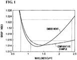
- Fig. 1 is a graph illustrating the wavelength dependency of a group index of each of an optical fiber according to an embodiment of the present invention and an optical fiber according to a comparative example.
- the zero-dispersion wavelength of the optical fiber according to the embodiment is 1303 nm.
- the zero-dispersion wavelength of the optical fiber according to the comparative example is 1480 nm.
- the wavelength at which the group index accords with the group index at a wavelength of 2400 nm is 1080 nm.
- the wavelength at which the group index accords with the group index at the wavelength of 2400 nm is 760 nm. Therefore, the optical fiber according to the embodiment can expand the SC-light band further toward the short wavelength side.
- the optical fiber according to the embodiment is composed of silica glass, has a zero-dispersion wavelength of 1290 nm to 1350 nm, and has an effective area Aeff of 14 ⁇ m 2 or smaller at a wavelength of 1550 nm.
- This optical fiber can increase the nonlinearity and can generate broadband SC light with a small fiber length with high efficiency.
- n 2 and ⁇ are values measured in a linearly-polarized state in accordance with the cross phase modulation (XPM) method.
- the nonlinear refractive index n 2 is preferably 6.0 ⁇ 10 -20 m 2 /W or larger.
- the value ⁇ at the wavelength of 1550 nm is preferably 20 [1/W/km] or larger, and more preferably 25 [1/W/km] or larger.
- the mode field diameter (MFD) at the wavelength of 1550 nm is preferably 4 ⁇ m or smaller, and more preferably 3.6 ⁇ m or smaller.
- a fiber cutoff wavelength of the optical fiber according to the embodiment is preferably 1650 nm or more and 2300 nm or less.
- the optical fiber according to the embodiment has a fiber cutoff wavelength longer than that of the optical fiber in the related art so that propagation light can be confined in the core more intensely, whereby the effect of waveguide dispersion in chromatic dispersion can be reduced.
- the zero-dispersion wavelength can be set to be closer to the lower limit (1272 nm) of the zero-dispersion wavelength determined based on the material dispersion of glass.
- the wavelength of the seed light may sometimes become shorter than the fiber cutoff wavelength.
- the seed light is mainly coupled with only the center of the core of the optical fiber at the input end of the optical fiber so that excitation of unwanted higher-order modes at the input end can be avoided.
- the differences in propagation constant between the fundamental mode and the higher-order modes are large, the light can be prevented from being coupled with the unwanted higher-order mode while propagating through the optical fiber, so that the seed light can be made to propagate substantially in a single mode.
- the chromatic dispersion of the optical fiber according to the embodiment at the wavelength of 1550 nm is preferably 10 ps/nm/km or more and 22 ps/nm/km or less. With the chromatic dispersion set in this range, the zero-dispersion wavelength can be set to be 1350 nm or shorter.
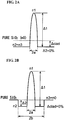
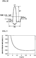
- Figs. 2A, 2B , and 2C schematically illustrate examples of refractive-index profiles of the optical fiber according to the embodiment.
- the optical fiber according to the embodiment has silica glass as a base and includes: a core having a refractive index n 1 and a diameter 2a and containing germanium (Ge); a depressed section that surrounds the core, has a refractive index n 2 and an outer diameter 2b, and contains fluorine (F); and cladding surrounding the depressed section and having a refractive index n 3 .
- the optical fiber according to the embodiment has the relationship n 1 > n 3 ⁇ n 2 .
- Fig. 2C illustrates a case where n 3 ⁇ n 0 , which can be realized by adding fluorine to the cladding.
- n 3 ⁇ n 0 shown in Fig. 2C , the amount of germanium to be added to the core for achieving the same ⁇ 1 can be reduced, as compared with Fig. 2B , so that the transmission loss can be reduced.
- the viscosity of the cladding which occupies a major portion of the volume of the optical fiber, can be reduced so that the drawing temperature can be reduced, whereby the transmission loss can be reduced.
- An amount of fluorine for providing a relative refractive-index difference ⁇ clad of -0.8% can be added.
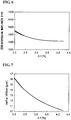
- Fig. 3 is a graph illustrating the relationship between the diameter 2a of the core and the zero-dispersion wavelength.
- Fig. 4 is a graph illustrating the relationship between the diameter 2a of the core and the effective area Aeff at the wavelength of 1550 nm.
- the diameter 2a of the core is preferably 4.0 ⁇ m or more and 6.0 ⁇ m or less.
- the zero-dispersion wavelength can be set to 1350 nm or shorter and the fiber cutoff wavelength can be set to 1650 nm or longer.
- the effective area Aeff is 14 ⁇ m 2 or larger, resulting in lower nonlinearity.
- Fig. 6 is a graph illustrating the relationship between the relative refractive-index difference ⁇ 1 of the core and the zero-dispersion wavelength.
- Fig. 7 is a graph illustrating the relationship between the relative refractive-index difference ⁇ 1 of the core and the effective area Aeff at the wavelength of 1550 nm.
- Fig. 8 is a graph illustrating the relationship between the relative refractive-index difference ⁇ 1 of the core and the fiber cutoff wavelength.
- the zero-dispersion wavelength can be set to 1350 nm or shorter and the effective area Aeff can be set to 14 ⁇ m 2 or smaller.
- the effective area Aeff can be set to 14 ⁇ m 2 or smaller.
- germanium that increases the relative refractive-index difference relative to pure SiO 2 to about 3.4% to the core, it is realistically difficult to add germanium with even higher concentration.
- fluorine that reduces the relative refractive-index difference relative to pure SiO 2 to about -0.8% to the depressed section, it is realistically difficult to add fluorine with even higher concentration.
- a realistic upper limit for ⁇ 1 is about 4.2%. Therefore, ⁇ 1 is preferably 2.4% or more and 4.2% or less, and is more preferably 3.0% or more and 4.2% or less.
- ⁇ 2 that provides a desired fiber cutoff wavelength may be selected.
- ⁇ 2 is preferably -0.8% or more and 0% or less, and is more preferably -0.8% or more and -0.3% or less in reality.
- Fig. 9 is a graph illustrating the relationship between b/a and the zero-dispersion wavelength.
- Fig. 10 is a graph illustrating the relationship between b/a and the effective area Aeff at the wavelength of 1550 nm.
- b/a is preferably 2.0 or more and 3.0 or less.
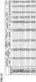
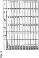
- Figs. 12 and 13 illustrate tables showing the specifications of an optical fiber according to a comparative example and optical fibers 1 to 18 according to practical examples.
- Fig. 12 shows a transmission loss at the wavelength of 1550 nm, a zero-dispersion wavelength, chromatic dispersion at the wavelength of 1550 nm, a dispersion slope at the wavelength of 1550 nm, a fiber cutoff wavelength, an effective area at the wavelength of 1550 nm, a mode field diameter at the wavelength of 1550 nm, a nonlinear refractive index n 2 , and a nonlinearity coefficient ⁇ at the wavelength of 1550 nm.
- Fig. 13 shows ⁇ 1, ⁇ 2, Aclad, 2a, and b/a.
- An ⁇ -th power expressing the shape of refractive-index distribution of the core in the optical fiber according to each practical example is about 1.6-th power to 3.0-th power.
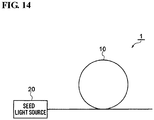
- Fig. 14 schematically illustrates a light source device 1 according to an embodiment.
- the light source device 1 includes an optical fiber 10 according to the above-described embodiment and a seed light source 20.
- the seed light source 20 outputs seed light whose central wavelength is 1000 nm or more and 1650 nm or less. More preferably, the seed light source 20 outputs seed light whose central wavelength is 1200 nm or more and 1400 nm or less.
- the seed light to be output from the seed light source 20 is high-intensity light, such as short-pulse light with the pulse width of picoseconds or femtoseconds, pulse light with the pulse width of about nanoseconds, or continuous light.
- the optical fiber 10 receives the seed light output from the seed light source 20 via one end thereof, allows the seed light to propagate therethrough, causes broadband light (SC light) to be generated in accordance with a nonlinear optical phenomenon while the seed light propagates through the optical fiber 10, and outputs the SC light from the other end of the optical fiber 10.
- SC light broadband light
- This light source device 1 can output SC light with a broader band than in the related art.
Landscapes
- Physics & Mathematics (AREA)
- Chemical & Material Sciences (AREA)
- Dispersion Chemistry (AREA)
- General Physics & Mathematics (AREA)
- Optics & Photonics (AREA)
- Nonlinear Science (AREA)
- Optical Modulation, Optical Deflection, Nonlinear Optics, Optical Demodulation, Optical Logic Elements (AREA)
- Optical Fibers, Optical Fiber Cores, And Optical Fiber Bundles (AREA)
- Glass Compositions (AREA)
Abstract
Description
- The present invention relates to optical fibers and light source devices.
- When high-intensity light, such as short-pulse light with the pulse width of picoseconds or femtoseconds, pulse light with the pulse width of about nanoseconds, or continuous light, propagates through a nonlinear medium, such as an optical fiber, it is known that broadband light is generated in accordance with a nonlinear optical phenomenon occurring in the nonlinear medium. The broadband light obtained in accordance with this phenomenon is called supercontinuum (SC) light. Because SC light has properties such as broadband, high powere, and flat spectrum, it is expected that such SC light is to be applied to, for example, optical measurement or near-infrared spectroscopy.
- W. J. Wadsworth, et al., "Supercontinuum and four-wave mixing with Q-switched pulses in endlessly single-mode photonic crystal fibres" OPTICS EXPRESS, Vol. 12, No. 2, pp. 299-309 describes a result in which SC light is generated by using a photonic crystal fiber (PCF) as an optical fiber that causes a nonlinear optical phenomenon to occur. However, a PCF has a special structure with a plurality of holes extending in the axial direction within the cross section of the fiber, and is problematic in that the manufacturing cost thereof is high.
- Thus, there have been many reports describing that SC light is generated by using a highly-nonlinear optical fiber that uses silica glass as a base, the highly-nonlinear optical fiber having a core with a high refractive index and a cladding with a low refractive index (for example, see
JP 2007-279704 A Patent Literature 1" hereinafter) andJP 2010-49089 A Patent Literature 2" hereinafter). These highly-nonlinear optical fibers have a simple solid structure without any holes. However, in the technology in the related art that uses highly-nonlinear optical fibers, it is difficult to expand the SC-light band to a long wavelength of 2400 nm or longer and to a short wavelength of 850 nm or shorter. - An object of the present invention to provide an optical fiber that high nonlinearity, and can cause broadband SC light to be generated with high efficiency, and a light source device that can output broadband SC light by using this optical fiber.
- An optical fiber according to the present invention is composed of silica glass, has a zero-dispersion wavelength of 1290 nm to 1350 nm, and has an effective area of 14 µm2 or smaller at a wavelength of 1550 nm.
- A fiber cutoff wavelength of the optical fiber according to the present invention may be 1650 nm or more and 2300 nm or less. Chromatic dispersion at the wavelength of 1550 nm may be 10 ps/nm/km or more and 22 ps/nm/km or less. A nonlinear refractive index at the wavelength of 1550 nm may be 6.0× 10⁻²⁰m2/W or larger.
- The optical fiber according to the present invention may include: a core having a refractive index n1 and a
diameter 2a and containing germanium; a depressed section that surrounds the core, has a refractive index n2 and anouter diameter 2b, and contains fluorine; and cladding surrounding the depressed section and having a refractive index n3. The optical fiber may have a relationship n1 > n3 ≥ n2. A relative refractive-index difference Δ1 of the core relative to the depressed section may be 3.0% or more and 4.2% or less, a relative refractive-index difference Δ2 of the depressed section relative to the cladding may be -0.8% or more and -0.3% or less, thediameter 2a may be 4.0 µm or more and 6.0 µm or less, and b/a may be 2.0 or more and 3.0 or less. Furthermore, a relative refractive-index difference Δclad of the cladding relative to pure silicon dioxide may be -0.8% or more and 0% or less. - A light source device according to the present invention includes a seed light source that outputs light whose central wavelength is 1000 nm or more and 1650 nm or less, and the optical fiber according to the present invention that receives the light output from the seed light source, allows the light to propagate through the optical fiber, causes broadband light with an expanded band to be generated in accordance with a nonlinear optical phenomenon while the light propagates through the optical fiber, and outputs the broadband light.
- The optical fiber according to the present invention has high nonlinearity, and can cause broadband SC light to be generated with high efficiency.
-
-
Figure 1 is a graph illustrating the wavelength dependency of a group index of each of an optical fiber according to an embodiment of the present invention and an optical fiber according to a comparative example. -
Figures 2A, 2B , and2C schematically illustrate examples of refractive-index profiles of the optical fiber according to the embodiment. -
Figure 3 is a graph illustrating the relationship between adiameter 2a of a core and a zero-dispersion wavelength. -
Figure 4 is a graph illustrating the relationship between thediameter 2a of the core and an effective area Aeff at a wavelength of 1550 nm. -
Figure 5 is a graph illustrating the relationship between thediameter 2a of the core and a fiber cutoff wavelength. -
Figure 6 is a graph illustrating the relationship between a relative refractive-index difference Δ1 of the core and the zero-dispersion wavelength. -
Figure 7 is a graph illustrating the relationship between the relative refractive-index difference Δ1 of the core and the effective area Aeff at the wavelength of 1550 nm. -
Figure 8 is a graph illustrating the relationship between the relative refractive-index difference Δ1 of the core and the fiber cutoff wavelength. -
Figure 9 is a graph illustrating the relationship between b/a and the zero-dispersion wavelength. -
Figure 10 is a graph illustrating the relationship between b/a and the effective area Aeff at the wavelength of 1550 nm. -
Figure 11 is a graph illustrating the relationship between b/a and the fiber cutoff wavelength. -
Figure 12 illustrates a table showing the specifications of an optical fiber according to a comparative example and optical fibers according to first to eighteenth practical examples. -
Figure 13 illustrates another table showing the specifications of the optical fiber according to the comparative example and the optical fibers according to first to eighteenth practical examples. -
Figure 14 schematically illustrates a light source device according to an embodiment of the present invention. - Embodiments of the present invention will be described in detail below with reference to the appended drawings. In the drawings, identical components are given the same reference signs, and redundant descriptions thereof will be omitted. The present invention is not to be limited to the following examples and is intended to include all modifications that are indicated by the scope of the claims and that have meanings equivalent to and within the scope of the claims.
- In the technology in the related art that uses highly-nonlinear optical fibers, it is difficult to expand the SC-light band to a long wavelength of 2400 nm or longer and to a short wavelength of 850 nm or shorter. The reasons for this are as follows. At the long wavelength side, the intensity of seed light attenuates due to infrared absorption of silica glass at 2400 nm or longer, thus making it impossible for a nonlinear optical phenomenon to occur. On the other hand, the limit at the shortest wavelength side is determined based on a wavelength at which a group index accords with a group index at the longest wavelength of the SC occurrence band. A group index of light propagating through an optical fiber becomes minimum at a zero-dispersion wavelength and increases therefrom both toward the short wavelength side and the long wavelength side. Therefore, in order to expand the SC-light band toward the short wavelength side by shortening the wavelength at which the group index accords with a group index at the longest wavelength, it is effective to set the zero-dispersion wavelength of the optical fiber at the short wavelength side as much as possible.
- The zero-dispersion wavelength of the optical fiber described in
Patent Literature 1 is between 1350 nm and 1570 nm. The zero-dispersion wavelength of the optical fiber described inPatent Literature 2 is 1284 nm. The optical fiber described inPatent Literature 2 has a zero-dispersion wavelength that is shorter than the zero-dispersion wavelength of the optical fiber described inPatent Literature 1. However, in the optical fiber described inPatent Literature 2, the core is composed of pure silica glass and has a large mode field diameter of about 10 µm at a wavelength of 1550 nm, meaning that the optical fiber has low nonlinearity. Therefore, this optical fiber is not capable of efficiently generating SC light and requires a length of about several tens of meters to one kilometer. Thus, in order to expand the band at the short wavelength side of the SC light, it is desirable that the zero-dispersion wavelength of the optical fiber be shorter than the zero-dispersion wavelength of 1350 nm to 1570 nm of the optical fiber described inPatent Literature 1. -
Fig. 1 is a graph illustrating the wavelength dependency of a group index of each of an optical fiber according to an embodiment of the present invention and an optical fiber according to a comparative example. The zero-dispersion wavelength of the optical fiber according to the embodiment is 1303 nm. The zero-dispersion wavelength of the optical fiber according to the comparative example is 1480 nm. In the optical fiber according to the comparative example, the wavelength at which the group index accords with the group index at a wavelength of 2400 nm is 1080 nm. In the optical fiber according to the embodiment, the wavelength at which the group index accords with the group index at the wavelength of 2400 nm is 760 nm. Therefore, the optical fiber according to the embodiment can expand the SC-light band further toward the short wavelength side. - The optical fiber according to the embodiment is composed of silica glass, has a zero-dispersion wavelength of 1290 nm to 1350 nm, and has an effective area Aeff of 14 µm2 or smaller at a wavelength of 1550 nm. This optical fiber can increase the nonlinearity and can generate broadband SC light with a small fiber length with high efficiency. A nonlinearity coefficient γ [1/W/km] indicating the nonlinearity of the optical fiber is expressed as follows:

- The nonlinear refractive index n2 is preferably 6.0×10⁻²⁰ m2/W or larger. The value γ at the wavelength of 1550 nm is preferably 20 [1/W/km] or larger, and more preferably 25 [1/W/km] or larger. The mode field diameter (MFD) at the wavelength of 1550 nm is preferably 4 µm or smaller, and more preferably 3.6 µm or smaller.
- A fiber cutoff wavelength of the optical fiber according to the embodiment is preferably 1650 nm or more and 2300 nm or less. The optical fiber according to the embodiment has a fiber cutoff wavelength longer than that of the optical fiber in the related art so that propagation light can be confined in the core more intensely, whereby the effect of waveguide dispersion in chromatic dispersion can be reduced. As a result, the zero-dispersion wavelength can be set to be closer to the lower limit (1272 nm) of the zero-dispersion wavelength determined based on the material dispersion of glass.
- If the fiber cutoff wavelength is long, the wavelength of the seed light may sometimes become shorter than the fiber cutoff wavelength. However, the seed light is mainly coupled with only the center of the core of the optical fiber at the input end of the optical fiber so that excitation of unwanted higher-order modes at the input end can be avoided. Furthermore, since the differences in propagation constant between the fundamental mode and the higher-order modes are large, the light can be prevented from being coupled with the unwanted higher-order mode while propagating through the optical fiber, so that the seed light can be made to propagate substantially in a single mode.
- The chromatic dispersion of the optical fiber according to the embodiment at the wavelength of 1550 nm is preferably 10 ps/nm/km or more and 22 ps/nm/km or less. With the chromatic dispersion set in this range, the zero-dispersion wavelength can be set to be 1350 nm or shorter.
-
Figs. 2A, 2B , and2C schematically illustrate examples of refractive-index profiles of the optical fiber according to the embodiment. The optical fiber according to the embodiment has silica glass as a base and includes: a core having a refractive index n1 and adiameter 2a and containing germanium (Ge); a depressed section that surrounds the core, has a refractive index n2 and anouter diameter 2b, and contains fluorine (F); and cladding surrounding the depressed section and having a refractive index n3. Moreover, the optical fiber according to the embodiment has the relationship n1 > n3 ≥ n2. - A relative refractive-index difference Δ1 [%] of the core relative to the depressed section, a relative refractive-index difference Δ2 [%] of the depressed section relative to the cladding, and a relative refractive-index difference Δclad [%] of the cladding relative to pure silicon dioxide (SiO2) (i.e., a refractive index n0) are expressed with the following expressions:


-
Fig. 2A illustrates a case where n2 = n3.Fig. 2B illustrates a case where n2 < n3 = n0.Fig. 2C illustrates a case where n3 < n0, which can be realized by adding fluorine to the cladding. With n3 < n0 shown inFig. 2C , the amount of germanium to be added to the core for achieving the same Δ1 can be reduced, as compared withFig. 2B , so that the transmission loss can be reduced. Moreover, by adding fluorine to the cladding, the viscosity of the cladding, which occupies a major portion of the volume of the optical fiber, can be reduced so that the drawing temperature can be reduced, whereby the transmission loss can be reduced. An amount of fluorine for providing a relative refractive-index difference Δclad of -0.8% can be added. -
Fig. 3 is a graph illustrating the relationship between thediameter 2a of the core and the zero-dispersion wavelength.Fig. 4 is a graph illustrating the relationship between thediameter 2a of the core and the effective area Aeff at the wavelength of 1550 nm.Fig. 5 is a graph illustrating the relationship between thediameter 2a of the core and the fiber cutoff wavelength. In this case, Δ1 = 4.1%, Δ2 = -0.5%, Δclad = -0.3%, and b/a = 2.6. - It is clear from
Figs. 3 ,4, and 5 that thediameter 2a of the core is preferably 4.0 µm or more and 6.0 µm or less. Referring toFigs. 3 and5 , by setting thediameter 2a of the core to 4.0 µm or larger, the zero-dispersion wavelength can be set to 1350 nm or shorter and the fiber cutoff wavelength can be set to 1650 nm or longer. On the other hand, referring toFig. 4 , when thediameter 2a of the core is 6.0 µm or smaller, the effective area Aeff is 14 µm2 or larger, resulting in lower nonlinearity. -
Fig. 6 is a graph illustrating the relationship between the relative refractive-index difference Δ1 of the core and the zero-dispersion wavelength.Fig. 7 is a graph illustrating the relationship between the relative refractive-index difference Δ1 of the core and the effective area Aeff at the wavelength of 1550 nm.Fig. 8 is a graph illustrating the relationship between the relative refractive-index difference Δ1 of the core and the fiber cutoff wavelength. In this case, b/a = 2.6 and 2a = 4.8 µm. Moreover, three patterns are set such that (Δ2, Δclad) = (0%, -0.8%), (-0.5%, -0.3%), and (-0.8%, 0%). In the graphs shown inFigs. 6 and 7 , these three patterns substantially overlap one another. - It is clear from
Figs. 6, 7 , and8 that, by setting Δ1 to 2.4% or larger, the zero-dispersion wavelength can be set to 1350 nm or shorter and the effective area Aeff can be set to 14 µm2 or smaller. Although it is possible to add an amount of germanium that increases the relative refractive-index difference relative to pure SiO2 to about 3.4% to the core, it is realistically difficult to add germanium with even higher concentration. Furthermore, although it is possible to add an amount of fluorine that reduces the relative refractive-index difference relative to pure SiO2 to about -0.8% to the depressed section, it is realistically difficult to add fluorine with even higher concentration. A realistic upper limit for Δ1 is about 4.2%. Therefore, Δ1 is preferably 2.4% or more and 4.2% or less, and is more preferably 3.0% or more and 4.2% or less. - Furthermore, it is clear from
Figs. 6, 7 , and8 that neither of the zero-dispersion wavelength and the effective area hardly changes even by changing Δ2 but only the fiber cutoff wavelength changes. Therefore, Δ2 that provides a desired fiber cutoff wavelength may be selected. However, since it is realistically difficult to add an amount of fluorine more than or equal to an amount at which the relative refractive-index difference relative to pure silica is equivalent to about -0.8%, Δ2 is preferably -0.8% or more and 0% or less, and is more preferably -0.8% or more and -0.3% or less in reality. -
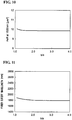
Fig. 9 is a graph illustrating the relationship between b/a and the zero-dispersion wavelength.Fig. 10 is a graph illustrating the relationship between b/a and the effective area Aeff at the wavelength of 1550 nm.Fig. 11 is a graph illustrating the relationship between b/a and the fiber cutoff wavelength. In this case, Δ1 = 4.1%, Δ2 = -0.5%, Δclad = -0.3%, and 2a = 4.4 µm. - It is clear from
Figs. 9 and10 that the zero-dispersion wavelength rapidly becomes longer when b/a is 2.0 or smaller. On the other hand, there is hardly any effect on the characteristics even when b/a is increased to 3.0 or larger. Therefore, b/a is preferably 2.0 or more and 3.0 or less. -
Figs. 12 and13 illustrate tables showing the specifications of an optical fiber according to a comparative example andoptical fibers 1 to 18 according to practical examples.Fig. 12 shows a transmission loss at the wavelength of 1550 nm, a zero-dispersion wavelength, chromatic dispersion at the wavelength of 1550 nm, a dispersion slope at the wavelength of 1550 nm, a fiber cutoff wavelength, an effective area at the wavelength of 1550 nm, a mode field diameter at the wavelength of 1550 nm, a nonlinear refractive index n2, and a nonlinearity coefficient γ at the wavelength of 1550 nm.Fig. 13 shows Δ1, Δ2, Aclad, 2a, and b/a. An α-th power expressing the shape of refractive-index distribution of the core in the optical fiber according to each practical example is about 1.6-th power to 3.0-th power. -
Fig. 14 schematically illustrates alight source device 1 according to an embodiment. Thelight source device 1 includes anoptical fiber 10 according to the above-described embodiment and aseed light source 20. Theseed light source 20 outputs seed light whose central wavelength is 1000 nm or more and 1650 nm or less. More preferably, theseed light source 20 outputs seed light whose central wavelength is 1200 nm or more and 1400 nm or less. The seed light to be output from theseed light source 20 is high-intensity light, such as short-pulse light with the pulse width of picoseconds or femtoseconds, pulse light with the pulse width of about nanoseconds, or continuous light. Theoptical fiber 10 receives the seed light output from theseed light source 20 via one end thereof, allows the seed light to propagate therethrough, causes broadband light (SC light) to be generated in accordance with a nonlinear optical phenomenon while the seed light propagates through theoptical fiber 10, and outputs the SC light from the other end of theoptical fiber 10. Thislight source device 1 can output SC light with a broader band than in the related art.
Claims (8)
- An optical fiber that is composed of silica glass, has a zero-dispersion wavelength of 1290 nm to 1350 nm, and has an effective area of 14 µm2 or smaller at a wavelength of 1550 nm.
- The optical fiber according to Claim 1,
wherein a fiber cutoff wavelength is 1650 nm or more and 2300 nm or less. - The optical fiber according to Claim 1 or 2,
wherein chromatic dispersion at the wavelength of 1550 nm is 10 ps/nm/km or more and 22 ps/nm/km or less. - The optical fiber according to any one of Claims 1 to 3,
wherein a nonlinear refractive index at the wavelength of 1550 nm is 6.0×10⁻²⁰m2/W or larger. - The optical fiber according to any one of Claims 1 to 4, comprising:a core having a refractive index n1 and a diameter 2a and containing germanium;a depressed section that surrounds the core, has a refractive index n2 and an outer diameter 2b, and contains fluorine; andcladding surrounding the depressed section and having a refractive index n3,wherein the optical fiber has a relationship n1 > n3 ≥ n2.
- The optical fiber according to Claim 5,
wherein a relative refractive-index difference Δ1 of the core relative to the depressed section is 3.0% or more and 4.2% or less,
wherein a relative refractive-index difference Δ2 of the depressed section relative to the cladding is -0.8% or more and -0.3% or less,
wherein the diameter 2a is 4.0 µm or more and 6.0 µm or less, and
wherein b/a is 2.0 or more and 3.0 or less. - The optical fiber according to Claim 5 or 6,
wherein a relative refractive-index difference Δclad of the cladding relative to pure silicon dioxide is -0.8% or more and 0% or less. - A light source device comprising:a seed light source that outputs light whose central wavelength is 1000 nm or more and 1650 nm or less; andthe optical fiber according to any one of Claims 1 to 7 that receives the light output from the seed light source, allows the light to propagate through the optical fiber, causes broadband light with an expanded band to be generated in accordance with a nonlinear optical phenomenon while the light propagates through the optical fiber, and outputs the broadband light.
Applications Claiming Priority (1)
| Application Number | Priority Date | Filing Date | Title |
|---|---|---|---|
| JP2015231627A JP6682826B2 (en) | 2015-11-27 | 2015-11-27 | Optical fiber and light source device |
Publications (2)
| Publication Number | Publication Date |
|---|---|
| EP3173830A1 true EP3173830A1 (en) | 2017-05-31 |
| EP3173830B1 EP3173830B1 (en) | 2019-10-30 |
Family
ID=57406079
Family Applications (1)
| Application Number | Title | Priority Date | Filing Date |
|---|---|---|---|
| EP16200440.2A Active EP3173830B1 (en) | 2015-11-27 | 2016-11-24 | Optical fiber and light source device |
Country Status (5)
| Country | Link |
|---|---|
| US (1) | US10451787B2 (en) |
| EP (1) | EP3173830B1 (en) |
| JP (1) | JP6682826B2 (en) |
| CN (1) | CN106908893B (en) |
| DK (1) | DK3173830T3 (en) |
Families Citing this family (1)
| Publication number | Priority date | Publication date | Assignee | Title |
|---|---|---|---|---|
| CN107272298B (en) * | 2017-07-31 | 2023-04-11 | 温州大学 | Device for generating atmosphere transmission window supercontinuum radiation and using method |
Citations (4)
| Publication number | Priority date | Publication date | Assignee | Title |
|---|---|---|---|---|
| US20020057880A1 (en) * | 2000-11-13 | 2002-05-16 | Sumitomo Electric Industries, Ltd. | Optical fiber and nonlinear optical fiber, optical amplifier and wavelength converter using the same, and method of making optical fiber |
| JP2007279704A (en) | 2006-03-15 | 2007-10-25 | Sumitomo Electric Ind Ltd | Optical fiber and broadband light source |
| JP2010049089A (en) | 2008-08-22 | 2010-03-04 | Sumitomo Electric Ind Ltd | Light source device |
| US20150016792A1 (en) * | 2012-03-02 | 2015-01-15 | Ofs Fitel, Llc | Highly nonlinear optical fiber with imporved sbs threshold and moderate attenuation |
Family Cites Families (10)
| Publication number | Priority date | Publication date | Assignee | Title |
|---|---|---|---|---|
| JPH10325913A (en) * | 1997-03-25 | 1998-12-08 | Furukawa Electric Co Ltd:The | Dispersion compensating optical fiber and WDM optical transmission line using the optical fiber |
| CN1237356C (en) * | 1999-07-27 | 2006-01-18 | 康宁股份有限公司 | Fiber with Power Limiting Notches |
| JP3783594B2 (en) * | 2000-11-13 | 2006-06-07 | 住友電気工業株式会社 | Optical fiber, nonlinear optical fiber, optical amplifier using the same, wavelength converter, and optical fiber manufacturing method |
| JP4443788B2 (en) * | 2001-03-30 | 2010-03-31 | 古河電気工業株式会社 | Optical fiber and optical communication system using the optical fiber |
| JP2003255169A (en) * | 2002-03-04 | 2003-09-10 | Furukawa Electric Co Ltd:The | Optical fiber, optical transmission line and optical transmission link using the optical fiber |
| US6904218B2 (en) * | 2003-05-12 | 2005-06-07 | Fitel U.S.A. Corporation | Super-large-effective-area (SLA) optical fiber and communication system incorporating the same |
| US6959137B2 (en) * | 2003-06-11 | 2005-10-25 | Fitel U.S.A. Corporation | Large-effective-area inverse dispersion compensating fiber, and a transmission line incorporating the same |
| JP4579710B2 (en) * | 2004-02-20 | 2010-11-10 | フルカワ エレクトリック ノース アメリカ インコーポレーテッド | Modification, enhancement and adjustment of light generation in highly nonlinear fibers by post-processing |
| US8731009B2 (en) * | 2009-04-08 | 2014-05-20 | Nkt Photonics A/S | Broadband high power light source |
| CN201689244U (en) * | 2010-04-16 | 2010-12-29 | 深圳大学 | A device for generating supercontinuum spectrum |
-
2015
- 2015-11-27 JP JP2015231627A patent/JP6682826B2/en not_active Expired - Fee Related
-
2016
- 2016-11-16 CN CN201611021925.XA patent/CN106908893B/en active Active
- 2016-11-21 US US15/356,857 patent/US10451787B2/en active Active
- 2016-11-24 DK DK16200440T patent/DK3173830T3/en active
- 2016-11-24 EP EP16200440.2A patent/EP3173830B1/en active Active
Patent Citations (5)
| Publication number | Priority date | Publication date | Assignee | Title |
|---|---|---|---|---|
| US20020057880A1 (en) * | 2000-11-13 | 2002-05-16 | Sumitomo Electric Industries, Ltd. | Optical fiber and nonlinear optical fiber, optical amplifier and wavelength converter using the same, and method of making optical fiber |
| JP2007279704A (en) | 2006-03-15 | 2007-10-25 | Sumitomo Electric Ind Ltd | Optical fiber and broadband light source |
| EP1995632A1 (en) * | 2006-03-15 | 2008-11-26 | Sumitomo Electric Industries, Ltd. | Optical fiber and broadband light source |
| JP2010049089A (en) | 2008-08-22 | 2010-03-04 | Sumitomo Electric Ind Ltd | Light source device |
| US20150016792A1 (en) * | 2012-03-02 | 2015-01-15 | Ofs Fitel, Llc | Highly nonlinear optical fiber with imporved sbs threshold and moderate attenuation |
Non-Patent Citations (1)
| Title |
|---|
| W. J. WADSWORTH ET AL.: "Supercontinuum and four-wave mixing with Q-switched pulses in endlessly single-mode photonic crystal fibres", OPTICS EXPRESS, vol. 12, no. 2, pages 299 - 309 |
Also Published As
| Publication number | Publication date |
|---|---|
| CN106908893B (en) | 2020-11-27 |
| US10451787B2 (en) | 2019-10-22 |
| US20170153375A1 (en) | 2017-06-01 |
| CN106908893A (en) | 2017-06-30 |
| JP2017097270A (en) | 2017-06-01 |
| DK3173830T3 (en) | 2019-11-25 |
| JP6682826B2 (en) | 2020-04-15 |
| EP3173830B1 (en) | 2019-10-30 |
Similar Documents
| Publication | Publication Date | Title |
|---|---|---|
| Liu et al. | Double-cladding structure dependence of guiding characteristics in six-fold symmetric photonic quasi-crystal fiber | |
| Tee et al. | Photonic Crystal Fiber in Photonic Crystal Fiber for Residual Dispersion Compensation Over ${\rm E}+{\rm S}+{\rm C}+{\rm L}+{\rm U} $ Wavelength Bands | |
| Ranka et al. | Visible continuum generation in air–silica microstructure optical fibers with anomalous dispersion at 800 nm | |
| CN101852887A (en) | Optical fiber and fiber device that chromatic dispersion is arranged | |
| US20090097810A1 (en) | Holey fiber | |
| US11366267B2 (en) | Optical fiber | |
| CN102959438A (en) | Large effective area fiber with graded index Ge-free core | |
| Petropoulos et al. | Soliton-self-frequency-shift effects and pulse compression in an anomalously dispersive high nonlinearity lead silicate holey fiber | |
| US8699833B2 (en) | Microstructured optical fiber and a device for generating broadband white light | |
| Van et al. | Supercontinuum generation in highly birefringent fiber infiltrated with carbon disulfide | |
| Yeom et al. | Tunable acoustic gratings in solid-core photonic bandgap fiber | |
| EP2690473B1 (en) | Optical fiber and optical transmission line | |
| EP3285100B1 (en) | Optical fiber design method | |
| EP3173830B1 (en) | Optical fiber and light source device | |
| García et al. | Numerical study of highly nonlinear photonic crystal fiber with tunable zero dispersion wavelengths | |
| US10310177B2 (en) | Photonic crystal fiber | |
| EP1582915B1 (en) | Microstructured fibre with non-linear index profile in the core | |
| Poli et al. | Optical parametric amplification in all-silica triangular-core photonic crystal fibers | |
| Qi et al. | Design and analysis of seven-core photonic crystal fiber for high-power visible supercontinuum generation | |
| Mahmud et al. | Management of residual dispersion of an optical transmission system using octagonal photonic crystal fiber | |
| Jespersen et al. | A higher-order-mode fiber delivery for Ti: Sapphire femtosecond lasers | |
| US20220011512A1 (en) | Optical fiber system employing topological guidance of light | |
| Rehan et al. | Multimode optical fibers: versatile platform for nonlinear applications | |
| Van et al. | Comparison of optical features in nitrobenzene-core photonic crystal fiber with hexagonal and square lattices in the claddings | |
| Khelladi | Study and Synthesis of the Propagation of Ultrashort Laser Pulses in Medias: Fused Silica, Photonic Crystal Fiber, Air Silica and Hollow Core |
Legal Events
| Date | Code | Title | Description |
|---|---|---|---|
| PUAI | Public reference made under article 153(3) epc to a published international application that has entered the european phase |
Free format text: ORIGINAL CODE: 0009012 |
|
| STAA | Information on the status of an ep patent application or granted ep patent |
Free format text: STATUS: THE APPLICATION HAS BEEN PUBLISHED |
|
| AK | Designated contracting states |
Kind code of ref document: A1 Designated state(s): AL AT BE BG CH CY CZ DE DK EE ES FI FR GB GR HR HU IE IS IT LI LT LU LV MC MK MT NL NO PL PT RO RS SE SI SK SM TR |
|
| AX | Request for extension of the european patent |
Extension state: BA ME |
|
| STAA | Information on the status of an ep patent application or granted ep patent |
Free format text: STATUS: REQUEST FOR EXAMINATION WAS MADE |
|
| 17P | Request for examination filed |
Effective date: 20170725 |
|
| RBV | Designated contracting states (corrected) |
Designated state(s): AL AT BE BG CH CY CZ DE DK EE ES FI FR GB GR HR HU IE IS IT LI LT LU LV MC MK MT NL NO PL PT RO RS SE SI SK SM TR |
|
| GRAP | Despatch of communication of intention to grant a patent |
Free format text: ORIGINAL CODE: EPIDOSNIGR1 |
|
| STAA | Information on the status of an ep patent application or granted ep patent |
Free format text: STATUS: GRANT OF PATENT IS INTENDED |
|
| INTG | Intention to grant announced |
Effective date: 20190627 |
|
| GRAS | Grant fee paid |
Free format text: ORIGINAL CODE: EPIDOSNIGR3 |
|
| GRAA | (expected) grant |
Free format text: ORIGINAL CODE: 0009210 |
|
| STAA | Information on the status of an ep patent application or granted ep patent |
Free format text: STATUS: THE PATENT HAS BEEN GRANTED |
|
| AK | Designated contracting states |
Kind code of ref document: B1 Designated state(s): AL AT BE BG CH CY CZ DE DK EE ES FI FR GB GR HR HU IE IS IT LI LT LU LV MC MK MT NL NO PL PT RO RS SE SI SK SM TR |
|
| REG | Reference to a national code |
Ref country code: GB Ref legal event code: FG4D |
|
| REG | Reference to a national code |
Ref country code: CH Ref legal event code: EP |
|
| REG | Reference to a national code |
Ref country code: AT Ref legal event code: REF Ref document number: 1196766 Country of ref document: AT Kind code of ref document: T Effective date: 20191115 |
|
| REG | Reference to a national code |
Ref country code: DE Ref legal event code: R096 Ref document number: 602016023237 Country of ref document: DE |
|
| REG | Reference to a national code |
Ref country code: DK Ref legal event code: T3 Effective date: 20191122 |
|
| REG | Reference to a national code |
Ref country code: IE Ref legal event code: FG4D |
|
| REG | Reference to a national code |
Ref country code: NL Ref legal event code: FP |
|
| REG | Reference to a national code |
Ref country code: LT Ref legal event code: MG4D |
|
| PG25 | Lapsed in a contracting state [announced via postgrant information from national office to epo] |
Ref country code: GR Free format text: LAPSE BECAUSE OF FAILURE TO SUBMIT A TRANSLATION OF THE DESCRIPTION OR TO PAY THE FEE WITHIN THE PRESCRIBED TIME-LIMIT Effective date: 20200131 Ref country code: PL Free format text: LAPSE BECAUSE OF FAILURE TO SUBMIT A TRANSLATION OF THE DESCRIPTION OR TO PAY THE FEE WITHIN THE PRESCRIBED TIME-LIMIT Effective date: 20191030 Ref country code: NO Free format text: LAPSE BECAUSE OF FAILURE TO SUBMIT A TRANSLATION OF THE DESCRIPTION OR TO PAY THE FEE WITHIN THE PRESCRIBED TIME-LIMIT Effective date: 20200130 Ref country code: LV Free format text: LAPSE BECAUSE OF FAILURE TO SUBMIT A TRANSLATION OF THE DESCRIPTION OR TO PAY THE FEE WITHIN THE PRESCRIBED TIME-LIMIT Effective date: 20191030 Ref country code: SE Free format text: LAPSE BECAUSE OF FAILURE TO SUBMIT A TRANSLATION OF THE DESCRIPTION OR TO PAY THE FEE WITHIN THE PRESCRIBED TIME-LIMIT Effective date: 20191030 Ref country code: FI Free format text: LAPSE BECAUSE OF FAILURE TO SUBMIT A TRANSLATION OF THE DESCRIPTION OR TO PAY THE FEE WITHIN THE PRESCRIBED TIME-LIMIT Effective date: 20191030 Ref country code: BG Free format text: LAPSE BECAUSE OF FAILURE TO SUBMIT A TRANSLATION OF THE DESCRIPTION OR TO PAY THE FEE WITHIN THE PRESCRIBED TIME-LIMIT Effective date: 20200130 Ref country code: PT Free format text: LAPSE BECAUSE OF FAILURE TO SUBMIT A TRANSLATION OF THE DESCRIPTION OR TO PAY THE FEE WITHIN THE PRESCRIBED TIME-LIMIT Effective date: 20200302 Ref country code: LT Free format text: LAPSE BECAUSE OF FAILURE TO SUBMIT A TRANSLATION OF THE DESCRIPTION OR TO PAY THE FEE WITHIN THE PRESCRIBED TIME-LIMIT Effective date: 20191030 |
|
| PG25 | Lapsed in a contracting state [announced via postgrant information from national office to epo] |
Ref country code: HR Free format text: LAPSE BECAUSE OF FAILURE TO SUBMIT A TRANSLATION OF THE DESCRIPTION OR TO PAY THE FEE WITHIN THE PRESCRIBED TIME-LIMIT Effective date: 20191030 Ref country code: RS Free format text: LAPSE BECAUSE OF FAILURE TO SUBMIT A TRANSLATION OF THE DESCRIPTION OR TO PAY THE FEE WITHIN THE PRESCRIBED TIME-LIMIT Effective date: 20191030 Ref country code: IS Free format text: LAPSE BECAUSE OF FAILURE TO SUBMIT A TRANSLATION OF THE DESCRIPTION OR TO PAY THE FEE WITHIN THE PRESCRIBED TIME-LIMIT Effective date: 20200229 |
|
| REG | Reference to a national code |
Ref country code: DE Ref legal event code: R119 Ref document number: 602016023237 Country of ref document: DE |
|
| PG25 | Lapsed in a contracting state [announced via postgrant information from national office to epo] |
Ref country code: AL Free format text: LAPSE BECAUSE OF FAILURE TO SUBMIT A TRANSLATION OF THE DESCRIPTION OR TO PAY THE FEE WITHIN THE PRESCRIBED TIME-LIMIT Effective date: 20191030 |
|
| REG | Reference to a national code |
Ref country code: CH Ref legal event code: PL |
|
| PG25 | Lapsed in a contracting state [announced via postgrant information from national office to epo] |
Ref country code: ES Free format text: LAPSE BECAUSE OF FAILURE TO SUBMIT A TRANSLATION OF THE DESCRIPTION OR TO PAY THE FEE WITHIN THE PRESCRIBED TIME-LIMIT Effective date: 20191030 Ref country code: LU Free format text: LAPSE BECAUSE OF NON-PAYMENT OF DUE FEES Effective date: 20191124 Ref country code: CZ Free format text: LAPSE BECAUSE OF FAILURE TO SUBMIT A TRANSLATION OF THE DESCRIPTION OR TO PAY THE FEE WITHIN THE PRESCRIBED TIME-LIMIT Effective date: 20191030 Ref country code: EE Free format text: LAPSE BECAUSE OF FAILURE TO SUBMIT A TRANSLATION OF THE DESCRIPTION OR TO PAY THE FEE WITHIN THE PRESCRIBED TIME-LIMIT Effective date: 20191030 Ref country code: LI Free format text: LAPSE BECAUSE OF NON-PAYMENT OF DUE FEES Effective date: 20191130 Ref country code: RO Free format text: LAPSE BECAUSE OF FAILURE TO SUBMIT A TRANSLATION OF THE DESCRIPTION OR TO PAY THE FEE WITHIN THE PRESCRIBED TIME-LIMIT Effective date: 20191030 Ref country code: CH Free format text: LAPSE BECAUSE OF NON-PAYMENT OF DUE FEES Effective date: 20191130 Ref country code: MC Free format text: LAPSE BECAUSE OF FAILURE TO SUBMIT A TRANSLATION OF THE DESCRIPTION OR TO PAY THE FEE WITHIN THE PRESCRIBED TIME-LIMIT Effective date: 20191030 |
|
| REG | Reference to a national code |
Ref country code: AT Ref legal event code: MK05 Ref document number: 1196766 Country of ref document: AT Kind code of ref document: T Effective date: 20191030 |
|
| REG | Reference to a national code |
Ref country code: BE Ref legal event code: MM Effective date: 20191130 |
|
| PG25 | Lapsed in a contracting state [announced via postgrant information from national office to epo] |
Ref country code: SM Free format text: LAPSE BECAUSE OF FAILURE TO SUBMIT A TRANSLATION OF THE DESCRIPTION OR TO PAY THE FEE WITHIN THE PRESCRIBED TIME-LIMIT Effective date: 20191030 Ref country code: IT Free format text: LAPSE BECAUSE OF FAILURE TO SUBMIT A TRANSLATION OF THE DESCRIPTION OR TO PAY THE FEE WITHIN THE PRESCRIBED TIME-LIMIT Effective date: 20191030 Ref country code: SK Free format text: LAPSE BECAUSE OF FAILURE TO SUBMIT A TRANSLATION OF THE DESCRIPTION OR TO PAY THE FEE WITHIN THE PRESCRIBED TIME-LIMIT Effective date: 20191030 |
|
| PLBE | No opposition filed within time limit |
Free format text: ORIGINAL CODE: 0009261 |
|
| STAA | Information on the status of an ep patent application or granted ep patent |
Free format text: STATUS: NO OPPOSITION FILED WITHIN TIME LIMIT |
|
| 26N | No opposition filed |
Effective date: 20200731 |
|
| PG25 | Lapsed in a contracting state [announced via postgrant information from national office to epo] |
Ref country code: IE Free format text: LAPSE BECAUSE OF NON-PAYMENT OF DUE FEES Effective date: 20191124 Ref country code: FR Free format text: LAPSE BECAUSE OF NON-PAYMENT OF DUE FEES Effective date: 20191230 Ref country code: DE Free format text: LAPSE BECAUSE OF NON-PAYMENT OF DUE FEES Effective date: 20200603 |
|
| PG25 | Lapsed in a contracting state [announced via postgrant information from national office to epo] |
Ref country code: BE Free format text: LAPSE BECAUSE OF NON-PAYMENT OF DUE FEES Effective date: 20191130 Ref country code: AT Free format text: LAPSE BECAUSE OF FAILURE TO SUBMIT A TRANSLATION OF THE DESCRIPTION OR TO PAY THE FEE WITHIN THE PRESCRIBED TIME-LIMIT Effective date: 20191030 Ref country code: SI Free format text: LAPSE BECAUSE OF FAILURE TO SUBMIT A TRANSLATION OF THE DESCRIPTION OR TO PAY THE FEE WITHIN THE PRESCRIBED TIME-LIMIT Effective date: 20191030 |
|
| PG25 | Lapsed in a contracting state [announced via postgrant information from national office to epo] |
Ref country code: CY Free format text: LAPSE BECAUSE OF FAILURE TO SUBMIT A TRANSLATION OF THE DESCRIPTION OR TO PAY THE FEE WITHIN THE PRESCRIBED TIME-LIMIT Effective date: 20191030 |
|
| GBPC | Gb: european patent ceased through non-payment of renewal fee |
Effective date: 20201124 |
|
| PG25 | Lapsed in a contracting state [announced via postgrant information from national office to epo] |
Ref country code: MT Free format text: LAPSE BECAUSE OF FAILURE TO SUBMIT A TRANSLATION OF THE DESCRIPTION OR TO PAY THE FEE WITHIN THE PRESCRIBED TIME-LIMIT Effective date: 20191030 Ref country code: HU Free format text: LAPSE BECAUSE OF FAILURE TO SUBMIT A TRANSLATION OF THE DESCRIPTION OR TO PAY THE FEE WITHIN THE PRESCRIBED TIME-LIMIT; INVALID AB INITIO Effective date: 20161124 |
|
| PG25 | Lapsed in a contracting state [announced via postgrant information from national office to epo] |
Ref country code: GB Free format text: LAPSE BECAUSE OF NON-PAYMENT OF DUE FEES Effective date: 20201124 |
|
| PGFP | Annual fee paid to national office [announced via postgrant information from national office to epo] |
Ref country code: NL Payment date: 20211014 Year of fee payment: 6 |
|
| PG25 | Lapsed in a contracting state [announced via postgrant information from national office to epo] |
Ref country code: TR Free format text: LAPSE BECAUSE OF FAILURE TO SUBMIT A TRANSLATION OF THE DESCRIPTION OR TO PAY THE FEE WITHIN THE PRESCRIBED TIME-LIMIT Effective date: 20191030 |
|
| PG25 | Lapsed in a contracting state [announced via postgrant information from national office to epo] |
Ref country code: MK Free format text: LAPSE BECAUSE OF FAILURE TO SUBMIT A TRANSLATION OF THE DESCRIPTION OR TO PAY THE FEE WITHIN THE PRESCRIBED TIME-LIMIT Effective date: 20191030 |
|
| P01 | Opt-out of the competence of the unified patent court (upc) registered |
Effective date: 20230515 |
|
| REG | Reference to a national code |
Ref country code: NL Ref legal event code: MM Effective date: 20221201 |
|
| PG25 | Lapsed in a contracting state [announced via postgrant information from national office to epo] |
Ref country code: NL Free format text: LAPSE BECAUSE OF NON-PAYMENT OF DUE FEES Effective date: 20221201 |
|
| PGFP | Annual fee paid to national office [announced via postgrant information from national office to epo] |
Ref country code: DK Payment date: 20251112 Year of fee payment: 10 |