EP3173748A1 - Device for volumetric measurement and/or control of a fluid - Google Patents
Device for volumetric measurement and/or control of a fluid Download PDFInfo
- Publication number
- EP3173748A1 EP3173748A1 EP16199403.3A EP16199403A EP3173748A1 EP 3173748 A1 EP3173748 A1 EP 3173748A1 EP 16199403 A EP16199403 A EP 16199403A EP 3173748 A1 EP3173748 A1 EP 3173748A1
- Authority
- EP
- European Patent Office
- Prior art keywords
- fluid
- impeller
- axis
- section
- diffuser
- Prior art date
- Legal status (The legal status is an assumption and is not a legal conclusion. Google has not performed a legal analysis and makes no representation as to the accuracy of the status listed.)
- Granted
Links
Images

Classifications
-
- G—PHYSICS
- G01—MEASURING; TESTING
- G01F—MEASURING VOLUME, VOLUME FLOW, MASS FLOW OR LIQUID LEVEL; METERING BY VOLUME
- G01F1/00—Measuring the volume flow or mass flow of fluid or fluent solid material wherein the fluid passes through a meter in a continuous flow
- G01F1/05—Measuring the volume flow or mass flow of fluid or fluent solid material wherein the fluid passes through a meter in a continuous flow by using mechanical effects
- G01F1/10—Measuring the volume flow or mass flow of fluid or fluent solid material wherein the fluid passes through a meter in a continuous flow by using mechanical effects using rotating vanes with axial admission
-
- G—PHYSICS
- G01—MEASURING; TESTING
- G01F—MEASURING VOLUME, VOLUME FLOW, MASS FLOW OR LIQUID LEVEL; METERING BY VOLUME
- G01F1/00—Measuring the volume flow or mass flow of fluid or fluent solid material wherein the fluid passes through a meter in a continuous flow
- G01F1/05—Measuring the volume flow or mass flow of fluid or fluent solid material wherein the fluid passes through a meter in a continuous flow by using mechanical effects
- G01F1/10—Measuring the volume flow or mass flow of fluid or fluent solid material wherein the fluid passes through a meter in a continuous flow by using mechanical effects using rotating vanes with axial admission
- G01F1/115—Measuring the volume flow or mass flow of fluid or fluent solid material wherein the fluid passes through a meter in a continuous flow by using mechanical effects using rotating vanes with axial admission with magnetic or electromagnetic coupling to the indicating device
Definitions
- the present invention relates to a device for volumetric measurement and/or control of a fluid, according to the preamble of claim 1.
- said device can be connected to a fluid supply line for a washing machine.
- the present invention also relates to a washing machine, in particular for household use, which comprises said device.
- Devices are known in the art for volumetric measurement and/or control of liquids and fluids in general flowing through ducts having a predetermined flow rate, to ensure exact control of the quantities of fluid flowing into containers or from a source.
- Such devices are used, for example, for dosing the water required by washing machines, in particular for household use (such as laundry washing machines and dishwashers), or in water distribution systems, in combination with a meter, and so on.
- Some known devices are mainly dedicated to controlling possible leaks or excessive flows of liquid, and therefore do not ensure a very accurate dosage; usually these devices are associated with an electrovalve that either allows or stops the flow, said electrovalve being normally open and being only closed when the device for volumetric fluid measurement and/or control detects an anomalous flow.
- a flow meter consisting of a tangential impeller, i.e. an impeller having an axis of rotation arranged substantially perpendicular to the direction of the flow to be measured and/or controlled; said tangential impeller is provided with metal inserts, and the device comprises a sensor for detecting the passage of such inserts, i.e. the revolutions made by the impeller when it is turned by a fluid flow.
- Devices for volumetric measurement and/or control are also known in the art which are so conceived as to include a flow meter consisting of an axial impeller, i.e. an impeller the axis of rotation of which is coaxial to the direction of the flow to be measured or controlled.
- the devices known in the art are often subject to malfunctions caused by the possible presence of impurities in the fluid flow to be measured or controlled.
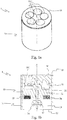
- reference numeral 1 designates as a whole a device for volumetric measurement and/or control of a fluid (indicated as F in Fig. 1b ) according to the present invention.
- the device 1 is preferably adapted to be associated with a washing machine, in particular for household use (not shown in the drawings), but the present invention is not strictly limited to such an apparatus or machine.
- the device 1 comprises a substantially tubular body 10 comprising a first portion 11 for the inlet of the fluid F into the body 10 and a second portion 12 for the outlet of said fluid F from the body 10.
- said first portion 11 can be associated with, for example, a tap (not shown in the drawings) of the water main
- said second portion 12 can be associated with, for example, a washing machine (not shown in the drawings).
- said first portion 11 and said second portion 12 may be associated with the water main and with a washing machine, respectively, through additional elements not shown in the annexed drawings.
- said body 10 may be a part of another component, such as, for example, a portion of an electrovalve (not shown in the drawings).
- said body 10 comprises at least one pair of supporting elements 13 extending radially within said body 10, in particular near said second portion 12, and converging towards a central portion 14 of the body 10.
- the device 1 comprises also an axial impeller 20 positioned in said body 10 in such a way that its axis of rotation A is substantially coaxial to the direction of the flow of fluid F to be measured or controlled, which flows from said first portion 11 to said second portion 12 within the body 10.
- said axis of rotation A of the impeller 20 substantially coincides with an axis A of the device 1.
- Said impeller 20 comprises a central core 21 from which a plurality of blades 22 extend.
- said blades 22 are of the helical type; also, they extend radially from the central core 21 and are joined in their outer part (i.e. that part of the blades 22 which is farthest from the central core 21) by a ring 23.
- the diameter of the impeller 20 is such as to determine the presence of a free passage between the ring 23 and the body 10 that houses it; said free passage is useful to promote the free rotation of the impeller 20 and to prevent the impeller 20 from seizing in the presence of small impurities.
- the device 1 further comprises a diffuser 30 arranged above the impeller 20 with respect to the flow of fluid F, in particular said diffuser 30 being adapted to convey the flow of fluid F towards the blades 22 of the impeller 20. As is particularly visible in Figure 1b , said diffuser 30 is associated with the body 10 in proximity to said first portion 11.
- the body 10 and the diffuser 30 are so shaped as to engage with each other, in particular by means of mutual fitting means (not shown in detail in the annexed drawings), thus forming, together with the impeller 20, a single compact structure that allows the various components to be pre-assembled easily and accurately.
- said compact structure facilitates the insertion of the device 1 into any duct or the like, wherever volumetric measurement and/or control of a flow of fluid is required.
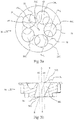
- Figure 3a shows a top view of the diffuser 30, whereas Figure 3b shows a sectional view along a line L-L (represented by means of a dashed-dotted line in Fig. 3a ) of the diffuser 30 of Figure 3a .
- said diffuser 30 comprises a plurality of ducts 30C, at least one duct 30C having a substantially circular section and a substantially helical trajectory (i.e. development).
- Said substantially circular section of at least one duct 31 can be appreciated in a plan view of the diffuser 30, i.e. a view essentially coinciding with the axis of rotation A of the impeller 20 and with the axis A of the device 1.
- said at least one duct 30C comprises a first section 31 for the inlet of the flow of fluid F into said duct 30C and a second section 32 for the outlet of the flow of fluid F from said duct 30C, said duct 30C getting progressively narrower in the part comprised between said first section 31 and said second section 32 (which are substantially perpendicular to the axis A of the device 1).
- the area of the first section 31 of the duct 30C is greater that the area of the second section 32 of said duct 30C.
- said first section 31 has a first centre 31C lying on a first axis A1
- said second section 32 has a second centre 32C lying on a second axis A2, said first axis A1 and second axis A2 being substantially parallel to the axis A of the device 1.
- a straight line R passing through said first centre 31C and second centre 32C is incident on said axis A of the device 1.
- Figure 3a also shows that said first centre 31C lies at a first distance d1 from the axis A of the device 1 and said second centre 32C lies at a second distance d2 from said axis A of the device 1; in a preferred embodiment, said first distance d1 is substantially equal to said second distance d2.
- all the ducts 30C of the diffuser 30 are made in substantially the same manner; it is however possible that at least one duct 30C is made differently than described in the present invention.
- the particular shape of the diffuser 30 according to the present invention allows realizing a device 1 for volumetric measurement and/or control of a fluid F which is very accurate in various operating conditions, at high and low pressures, also with different flow rates of the fluid F.
- the peculiar realization of the ducts 30C allows obtaining a device 1 for volumetric measurement and/or control of a fluid F that features improved reading linearity characteristics and which can detect the flow of fluid F with an optimal tolerance, while remaining essentially insensitive to pressure and/or flow variations.
- this particular configuration of the ducts 30C forces the flow of fluid F to divide and follow definite paths, so that every single flow thus obtained will hit the blades 22 of the impeller 20 at an exact angle and at a precise and predetermined distance from the axis of rotation A of the impeller 20.
- the provisions of the present invention allow providing a device 1 that can ensure optimal operation even in the presence of some impurities.
- the device 1 according to the present invention is also simple, economical and small.
- N n+1, where "N" is the number of ducts 30C and "n" is the number of blades 22.
- the device 1 comprises a pin 40 associated with the central core 21 of the impeller 20 and with the central portion 14 of the body 10, said pin 40 being adapted to allow the impeller 20 to turn.
- the pin 40 is represented as a separate element; it is however clear that it may be made as one piece with the impeller 20 or with said central portion 14 of the body 10.
- the device 1 according to the present invention further comprises detection means 24 associated with the impeller 20, which allow counting the revolutions of said impeller 20 as the fluid F flows through.
- said detection means may comprise at least one magnetic element 24 associated with the impeller 20; for example, said at least one magnetic element 24 may be associated with at least one of said blades 22 or with the ring 23 of the impeller 20; in this case, said detection means will comprise a detection unit (not shown in the drawings), located externally to the body 10 of the device 1, in particular aligned with said at least one magnetic element 24 of the impeller 20, so as to be able to detect the passage thereof and count the revolutions of said impeller 20.
- said detection means 24 may also comprise optical elements (not shown in the drawings) adapted to be detected by a suitable detection unit (also not shown in the drawings).
- the device 1 may also comprise at least one counterweight 25 associated with the impeller 20 in order to balance the weight of said at least one magnetic element 24 and allow the impeller 20 to move and turn adequately when the blades 22 are hit by the flow of fluid F.
- the provision of the diffuser 30 according to the present invention allows realizing a device 1 for volumetric measurement and/or control of a fluid F which is very accurate in various operating conditions, at high and low pressures, also with different flow rates of the fluid F.
- the peculiar configuration of the ducts 30C allows obtaining a device 1 for volumetric measurement and/or control of a fluid F that features improved reading linearity characteristics, said configuration of the ducts 30C making it possible to detect the flow of fluid F with an optimal tolerance, while remaining essentially insensitive to pressure and/or flow variations.
- the provisions of the present invention allow providing a device 1 that can ensure optimal operation even in the presence of impurities, while being simple, economical and small.
- the arrangement and number of ducts 30C allow obtaining a constant revolution speed of the impeller 20, so as to avoid that said impeller 20 might stall.
- a further advantage of the device 1 according to the present invention is due to the fact that the body 10 and the diffuser 30 are so shaped as to engage with each other, in particular by means of mutual fitting means (not shown in detail in the annexed drawings), thus forming, together with the impeller 20, a single compact structure that allows the various components to be pre-assembled easily and accurately.
- said compact structure facilitates the insertion of the device 1 into any duct or the like, wherever volumetric measurement and/or control of a flow of fluid is required.
Landscapes
- Physics & Mathematics (AREA)
- Fluid Mechanics (AREA)
- General Physics & Mathematics (AREA)
- Electromagnetism (AREA)
- Measuring Volume Flow (AREA)
- Structures Of Non-Positive Displacement Pumps (AREA)
- Reciprocating Pumps (AREA)
Abstract
- a substantially tubular body (10), said body (10) comprising a first portion (11) for the inlet of the fluid (F) into the body (10) and a second portion (12) for the outlet of said fluid (F) from the body (10);
- an impeller (20) positioned in said body (10) in such a way as to have an axis of rotation (A) substantially coaxial to the direction of the flow of fluid (F) to be measured or controlled, which flows from said first portion (11) to said second portion (12) within the body (10), in particular said axis of rotation (A) substantially coinciding with an axis (A) of the device (1);
- a diffuser (30) arranged above the impeller (20) with respect to the flow of fluid (F), in particular said diffuser (30) being adapted to convey the flow of fluid (F) towards the blades (22) of the impeller (20).
Description
- The present invention relates to a device for volumetric measurement and/or control of a fluid, according to the preamble of
claim 1. - In particular, said device can be connected to a fluid supply line for a washing machine.
- Therefore, the present invention also relates to a washing machine, in particular for household use, which comprises said device.
- Devices are known in the art for volumetric measurement and/or control of liquids and fluids in general flowing through ducts having a predetermined flow rate, to ensure exact control of the quantities of fluid flowing into containers or from a source. Such devices are used, for example, for dosing the water required by washing machines, in particular for household use (such as laundry washing machines and dishwashers), or in water distribution systems, in combination with a meter, and so on.
- Some known devices are mainly dedicated to controlling possible leaks or excessive flows of liquid, and therefore do not ensure a very accurate dosage; usually these devices are associated with an electrovalve that either allows or stops the flow, said electrovalve being normally open and being only closed when the device for volumetric fluid measurement and/or control detects an anomalous flow.
- Other known devices for volumetric measurement and/or control are designed to include a flow meter consisting of a tangential impeller, i.e. an impeller having an axis of rotation arranged substantially perpendicular to the direction of the flow to be measured and/or controlled; said tangential impeller is provided with metal inserts, and the device comprises a sensor for detecting the passage of such inserts, i.e. the revolutions made by the impeller when it is turned by a fluid flow.
- These known devices suffer from some drawbacks, since the use of tangential impellers does not always ensure high precision; in addition, the use of such tangential impellers makes the entire volumetric control device complex, bulky, expensive and difficult to maintain and repair.
- The devices disclosed in documents
US-A-5.007.453 andUS-A-4.428.088 are examples of the above-mentioned prior art. - Devices for volumetric measurement and/or control are also known in the art which are so conceived as to include a flow meter consisting of an axial impeller, i.e. an impeller the axis of rotation of which is coaxial to the direction of the flow to be measured or controlled.
- However, also those known devices that comprise an axial impeller suffer from a few drawbacks, since such devices are too sensitive to pressure and/or flow variations of the fluid to be measured or controlled, this sensitivity not allowing for effective and accurate measurement and/or control of said fluid flow.
- It is also well known that prior-art devices suffer from many problems caused by incorrect incidence of the fluid flow to be measured and/or controlled on the impeller, leading to undesired creation of turbulences at the inlet and/or outlet of the flow meter, resulting in pressure drops, especially at low pressures. Inevitably, these drawbacks adversely affect the behaviour and proper operation of the device.
- Moreover, the devices known in the art are often subject to malfunctions caused by the possible presence of impurities in the fluid flow to be measured or controlled.
- In this frame, it is the main object of the present invention to provide a device for volumetric measurement and/or control of a fluid and a related washing machine comprising said device, which are so realized as to overcome the drawbacks of the prior art.
- It is another object of the present invention to provide a device for volumetric measurement and/or control of a fluid which is sufficiently accurate in various operating conditions, at high and low pressures, also with different flow rates. It is a further object of the present invention to provide a device for volumetric measurement and/or control of a fluid which can ensure optimal operation even in the presence of large amounts of impurities, and which is simple, economical and as small as possible.
- Said objects are achieved by the present invention through a device for volumetric measurement and/or control of a fluid, and a related washing machine, incorporating the features set out in the appended claims, which are an integral part of the present description.
- Further objects, features and advantages of the present invention will become apparent from the following detailed description and from the annexed drawings, which are supplied by way of non-limiting explanatory example, wherein:
-
Figs. 1a and 1b show, respectively, a perspective view and a sectional view of a device for volumetric measurement and/or control of a fluid according to the present invention; -
Fig. 2 is an exploded view of the device ofFigs. 1a and 1b ; -
Figs. 3a and 3b show, respectively, a top view of a component of the device for volumetric measurement and/or control of a fluid according to the present invention and a sectional view along a line L-L of the component ofFig. 3a . - Said description and said drawings are to be considered as non-limiting explanatory examples.
- In
Figures 1a to 2b ,reference numeral 1 designates as a whole a device for volumetric measurement and/or control of a fluid (indicated as F inFig. 1b ) according to the present invention. - In the following description, reference will mostly be made to the fact that the
device 1 is preferably adapted to be associated with a washing machine, in particular for household use (not shown in the drawings), but the present invention is not strictly limited to such an apparatus or machine. - The
device 1 comprises a substantiallytubular body 10 comprising afirst portion 11 for the inlet of the fluid F into thebody 10 and asecond portion 12 for the outlet of said fluid F from thebody 10. In a preferred embodiment, saidfirst portion 11 can be associated with, for example, a tap (not shown in the drawings) of the water main, and saidsecond portion 12 can be associated with, for example, a washing machine (not shown in the drawings). Of course, saidfirst portion 11 and saidsecond portion 12 may be associated with the water main and with a washing machine, respectively, through additional elements not shown in the annexed drawings. It should be noted that saidbody 10 may be a part of another component, such as, for example, a portion of an electrovalve (not shown in the drawings). - In a preferred embodiment, said
body 10 comprises at least one pair of supportingelements 13 extending radially within saidbody 10, in particular near saidsecond portion 12, and converging towards acentral portion 14 of thebody 10. - The
device 1 comprises also anaxial impeller 20 positioned in saidbody 10 in such a way that its axis of rotation A is substantially coaxial to the direction of the flow of fluid F to be measured or controlled, which flows from saidfirst portion 11 to saidsecond portion 12 within thebody 10. - It should be noted that said axis of rotation A of the
impeller 20 substantially coincides with an axis A of thedevice 1. - Said
impeller 20 comprises acentral core 21 from which a plurality ofblades 22 extend. In particular, saidblades 22 are of the helical type; also, they extend radially from thecentral core 21 and are joined in their outer part (i.e. that part of theblades 22 which is farthest from the central core 21) by aring 23. Preferably (as is particularly visible inFig. 1b ), the diameter of theimpeller 20 is such as to determine the presence of a free passage between thering 23 and thebody 10 that houses it; said free passage is useful to promote the free rotation of theimpeller 20 and to prevent theimpeller 20 from seizing in the presence of small impurities. - Moreover, the
ring 23 prevents any lateral leaks of fluid F, particularly in the region comprised between the outer ends of theblades 22 and thecylindrical body 10 within which theimpeller 10 can rotate freely; therefore, saidring 23 is useful to avoid possible efficiency losses in the detection of the flow of fluid F. Thedevice 1 further comprises adiffuser 30 arranged above theimpeller 20 with respect to the flow of fluid F, in particular saiddiffuser 30 being adapted to convey the flow of fluid F towards theblades 22 of theimpeller 20. As is particularly visible inFigure 1b , saiddiffuser 30 is associated with thebody 10 in proximity to saidfirst portion 11. - Preferably, the
body 10 and thediffuser 30 are so shaped as to engage with each other, in particular by means of mutual fitting means (not shown in detail in the annexed drawings), thus forming, together with theimpeller 20, a single compact structure that allows the various components to be pre-assembled easily and accurately. As a result, said compact structure facilitates the insertion of thedevice 1 into any duct or the like, wherever volumetric measurement and/or control of a flow of fluid is required. -
Figure 3a shows a top view of thediffuser 30, whereasFigure 3b shows a sectional view along a line L-L (represented by means of a dashed-dotted line inFig. 3a ) of thediffuser 30 ofFigure 3a . - As is particularly visible in such Figures, according to the present invention said
diffuser 30 comprises a plurality ofducts 30C, at least oneduct 30C having a substantially circular section and a substantially helical trajectory (i.e. development). - Said substantially circular section of at least one
duct 31 can be appreciated in a plan view of thediffuser 30, i.e. a view essentially coinciding with the axis of rotation A of theimpeller 20 and with the axis A of thedevice 1. - In particular, said at least one
duct 30C comprises afirst section 31 for the inlet of the flow of fluid F into saidduct 30C and asecond section 32 for the outlet of the flow of fluid F from saidduct 30C, saidduct 30C getting progressively narrower in the part comprised between saidfirst section 31 and said second section 32 (which are substantially perpendicular to the axis A of the device 1). In fact, as is particularly visible inFig. 3b , the area of thefirst section 31 of theduct 30C is greater that the area of thesecond section 32 of saidduct 30C. Moreover, saidfirst section 31 has afirst centre 31C lying on a first axis A1, whereas saidsecond section 32 has asecond centre 32C lying on a second axis A2, said first axis A1 and second axis A2 being substantially parallel to the axis A of thedevice 1. This means that, in a side view of the diffuser 30 (such as, for example, the section ofFigure 3b ), a straight line R passing through saidfirst centre 31C andsecond centre 32C is incident on said axis A of thedevice 1. - It should be noted that in
Figure 3b said straight line R is indicated as a dotted line. -
Figure 3a also shows that saidfirst centre 31C lies at a first distance d1 from the axis A of thedevice 1 and saidsecond centre 32C lies at a second distance d2 from said axis A of thedevice 1; in a preferred embodiment, said first distance d1 is substantially equal to said second distance d2. - In a preferred embodiment, all the
ducts 30C of thediffuser 30 are made in substantially the same manner; it is however possible that at least oneduct 30C is made differently than described in the present invention. - The particular shape of the
diffuser 30 according to the present invention allows realizing adevice 1 for volumetric measurement and/or control of a fluid F which is very accurate in various operating conditions, at high and low pressures, also with different flow rates of the fluid F. - In particular, the peculiar realization of the
ducts 30C allows obtaining adevice 1 for volumetric measurement and/or control of a fluid F that features improved reading linearity characteristics and which can detect the flow of fluid F with an optimal tolerance, while remaining essentially insensitive to pressure and/or flow variations. - As a matter of fact, this particular configuration of the
ducts 30C forces the flow of fluid F to divide and follow definite paths, so that every single flow thus obtained will hit theblades 22 of theimpeller 20 at an exact angle and at a precise and predetermined distance from the axis of rotation A of theimpeller 20. - Also, the provisions of the present invention allow providing a
device 1 that can ensure optimal operation even in the presence of some impurities. - The
device 1 according to the present invention is also simple, economical and small. - In a preferred embodiment, the number of said plurality of
ducts 30C and the number of said plurality ofblades 22 are different and do not have a common denominator; in particular, said plurality ofducts 30C comprises a number ofducts 30C which is greater than the number ofblades 22; preferably, said plurality ofducts 30C comprises a number ofducts 30C which exceeds the number ofblades 22 by one unit (so as to satisfy the following relation: N=n+1, where "N" is the number ofducts 30C and "n" is the number of blades 22). This provision allows obtaining a constant revolution speed of theimpeller 20 and avoiding that saidimpeller 20 might stall. - As can be seen in the annexed drawings, the
device 1 comprises apin 40 associated with thecentral core 21 of theimpeller 20 and with thecentral portion 14 of thebody 10, saidpin 40 being adapted to allow theimpeller 20 to turn. In the example shown in the annexed drawings, thepin 40 is represented as a separate element; it is however clear that it may be made as one piece with theimpeller 20 or with saidcentral portion 14 of thebody 10. - The
device 1 according to the present invention further comprises detection means 24 associated with theimpeller 20, which allow counting the revolutions of saidimpeller 20 as the fluid F flows through. - In particular, said detection means may comprise at least one
magnetic element 24 associated with theimpeller 20; for example, said at least onemagnetic element 24 may be associated with at least one of saidblades 22 or with thering 23 of theimpeller 20; in this case, said detection means will comprise a detection unit (not shown in the drawings), located externally to thebody 10 of thedevice 1, in particular aligned with said at least onemagnetic element 24 of theimpeller 20, so as to be able to detect the passage thereof and count the revolutions of saidimpeller 20. - It is clear that, in accordance with the present invention, said detection means 24 may also comprise optical elements (not shown in the drawings) adapted to be detected by a suitable detection unit (also not shown in the drawings).
- The
device 1 may also comprise at least onecounterweight 25 associated with theimpeller 20 in order to balance the weight of said at least onemagnetic element 24 and allow theimpeller 20 to move and turn adequately when theblades 22 are hit by the flow of fluid F. - The features and advantages of the
device 1 according to the present invention and of the related washing machine are apparent from the above description. - In particular, the provision of the
diffuser 30 according to the present invention allows realizing adevice 1 for volumetric measurement and/or control of a fluid F which is very accurate in various operating conditions, at high and low pressures, also with different flow rates of the fluid F. - In particular, the peculiar configuration of the
ducts 30C allows obtaining adevice 1 for volumetric measurement and/or control of a fluid F that features improved reading linearity characteristics, said configuration of theducts 30C making it possible to detect the flow of fluid F with an optimal tolerance, while remaining essentially insensitive to pressure and/or flow variations. Furthermore, the provisions of the present invention allow providing adevice 1 that can ensure optimal operation even in the presence of impurities, while being simple, economical and small. - The arrangement and number of
ducts 30C allow obtaining a constant revolution speed of theimpeller 20, so as to avoid that saidimpeller 20 might stall. - A further advantage of the
device 1 according to the present invention is due to the fact that thebody 10 and thediffuser 30 are so shaped as to engage with each other, in particular by means of mutual fitting means (not shown in detail in the annexed drawings), thus forming, together with theimpeller 20, a single compact structure that allows the various components to be pre-assembled easily and accurately. As a result, said compact structure facilitates the insertion of thedevice 1 into any duct or the like, wherever volumetric measurement and/or control of a flow of fluid is required. - The device for volumetric measurement and/or control of a fluid and the related washing machine described herein by way of example may be subject to many possible variations without departing from the novelty spirit of the inventive idea; it is also clear that in the practical implementation of the invention the illustrated details may have different shapes or be replaced with other technically equivalent elements.
- It can therefore be easily understood that the present invention is not limited to the above-described device and washing machine, but may be subject to many modifications, improvements or replacements of equivalent parts and elements without departing from the inventive idea, as clearly specified in the following claims.
Claims (15)
- Device (1) for volumetric measurement and/or control of a fluid (F), of the type comprising:- a substantially tubular body (10), said body (10) comprising a first portion (11) for the inlet of the fluid (F) into the body (10) and a second portion (12) for the outlet of said fluid (F) from the body (10);- an impeller (20) positioned in said body (10) in such a way as to have an axis of rotation (A) substantially coaxial to the direction of the flow of fluid (F) to be measured or controlled, which flows from said first portion (11) to said second portion (12) within the body (10), in particular said axis of rotation (A) substantially coinciding with an axis (A) of the device (1);- a diffuser (30) arranged above the impeller (20) with respect to the flow of fluid (F), in particular said diffuser (30) being adapted to convey the flow of fluid (F) towards the blades (22) of the impeller (20),characterized in that
said diffuser (30) comprises a plurality of ducts (30C), at least one duct (30) of said plurality of ducts (30C) having a substantially circular section and a substantially helical trajectory. - Device (1) according to claim 1, characterized in that said at least one duct (30C) comprises a first section (31) for the inlet of the flow of fluid (F) into said duct (30C) and a second section (32) for the outlet of the flow of fluid (F) from said duct (30C), said duct (30C) getting progressively narrower in the part comprised between said first section (31) and said second section (32).
- Device (1) according to claim 2, characterized in that the area of the first section (31) of the duct (30C) is greater than the area of the second section (32) of said duct (30C).
- Device (1) according to one or more of claims 2 and 3, characterized in that said first section (31) has a first centre (31C) lying on a first axis (A1), whereas said second section (32) has a second centre (32C) lying on a second axis (A2), said first axis (A1) and second axis (A2) being substantially parallel to the axis (A) of the device (1).
- Device (1) according to one or more of claims 2 to 4, characterized in that, in a side view of the diffuser (30), a straight line (R) passing through said first centre (31C) and second centre (32C) is incident with respect to said axis (A) of the device (1).
- Device (1) according to one or more of the preceding claims, characterized in that said first centre (31C) lies at a first distance (d1) from the axis (A) of the device (1) and said second centre (32C) lies at a second distance (d2) from said axis (A) of the device (1), in particular said first distance (d1) being substantially equal to said second distance (d2).
- Device (1) according to one or more of the preceding claims, characterized in that all the ducts (30C) of said plurality of ducts (30C) are made in substantially the same manner.
- Device (1) according to one or more of the preceding claims, characterized in that said impeller (20) comprises a central core (21) from which a plurality of blades (22) extend, in particular said blades (22) being of the helical type.
- Device (1) according to claim 8, characterized in that said blades (22) extend radially from the central core (21) and are joined in their outer part by a ring (23).
- Device (1) according to claim 9, characterized in that the diameter of the impeller (20) is such as to determine the presence of a free passage between the ring (23) and the body (10).
- Device (1) according to one or more of the preceding claims, characterized in that said diffuser (30) is associated with the body (10) in proximity to said first portion (11).
- Device (1) according to one or more of the preceding claims, characterized in that the body (10) and the diffuser (30) are so shaped as to engage with each other, in particular through mutual fitting means, thus forming a single compact structure together with the impeller (20).
- Device (1) according to one or more of the preceding claims, characterized in that the number of said plurality of ducts (30C) and the number of said plurality of blades (22) are different.
- Device (1) according to one or more of the preceding claims, characterized in that it comprises detection means (24) associated with the impeller (20), which allow counting the revolutions of said impeller (20) as the fluid (F) flows through.
- Washing machine, in particular for household use, which comprises a device (1) according to one or more of the preceding claims 1 to 14.
Priority Applications (1)
| Application Number | Priority Date | Filing Date | Title |
|---|---|---|---|
| PL16199403T PL3173748T3 (en) | 2015-11-25 | 2016-11-17 | Device for volumetric measurement and/or control of a fluid |
Applications Claiming Priority (1)
| Application Number | Priority Date | Filing Date | Title |
|---|---|---|---|
| ITUB2015A005897A ITUB20155897A1 (en) | 2015-11-25 | 2015-11-25 | DEVICE FOR MEASURING AND VOLUMETRIC CONTROL OF A FLUID |
Publications (2)
| Publication Number | Publication Date |
|---|---|
| EP3173748A1 true EP3173748A1 (en) | 2017-05-31 |
| EP3173748B1 EP3173748B1 (en) | 2020-04-22 |
Family
ID=55538404
Family Applications (1)
| Application Number | Title | Priority Date | Filing Date |
|---|---|---|---|
| EP16199403.3A Active EP3173748B1 (en) | 2015-11-25 | 2016-11-17 | Device for volumetric measurement and/or control of a fluid |
Country Status (3)
| Country | Link |
|---|---|
| EP (1) | EP3173748B1 (en) |
| IT (1) | ITUB20155897A1 (en) |
| PL (1) | PL3173748T3 (en) |
Cited By (2)
| Publication number | Priority date | Publication date | Assignee | Title |
|---|---|---|---|---|
| US20190071326A1 (en) * | 2018-04-28 | 2019-03-07 | Foshan Midea Chungho Water Purification Equipment Co., Ltd. | Water softener |
| WO2023142836A1 (en) * | 2022-01-27 | 2023-08-03 | 约克广州空调冷冻设备有限公司 | Flow equalizing device and diverting device |
Citations (6)
| Publication number | Priority date | Publication date | Assignee | Title |
|---|---|---|---|---|
| US4428088A (en) | 1981-06-11 | 1984-01-31 | Whirlpool Corporation | Automatic liquid level control for automatic washers |
| US5007453A (en) | 1989-04-19 | 1991-04-16 | Yehuda Berkowitz | Fluid flow control device |
| EP0517293A1 (en) * | 1991-06-06 | 1992-12-09 | ELTEK S.p.A. | Integrated device for controlling the volume of fluids flowing through electrovalves for liquid distributing machines and washing machines |
| EP0599341A2 (en) * | 1992-11-27 | 1994-06-01 | ELTEK S.p.A. | Device for the measuring and/or the volumetric control of a fluid |
| US5929345A (en) * | 1995-06-06 | 1999-07-27 | Eltek S.P.A. | Device for the control of the quantity and/or the flow rate of a liquid |
| WO2003106323A2 (en) * | 2002-06-17 | 2003-12-24 | Eltek S.P.A. | Device for measuring or checking a fluid, in particular for drink vendors, and method for manufacturing said device |
Family Cites Families (2)
| Publication number | Priority date | Publication date | Assignee | Title |
|---|---|---|---|---|
| US6874372B2 (en) * | 2003-06-20 | 2005-04-05 | Elbi International S.P.A. | Device for measuring the flow rate of fluids |
| IT1405610B1 (en) * | 2010-06-14 | 2014-01-17 | Elbi Int Spa | ELECTROVALVE GROUP FOR THE DISPENSING OF COLD WATER IN A REFRIGERATOR |
-
2015
- 2015-11-25 IT ITUB2015A005897A patent/ITUB20155897A1/en unknown
-
2016
- 2016-11-17 PL PL16199403T patent/PL3173748T3/en unknown
- 2016-11-17 EP EP16199403.3A patent/EP3173748B1/en active Active
Patent Citations (6)
| Publication number | Priority date | Publication date | Assignee | Title |
|---|---|---|---|---|
| US4428088A (en) | 1981-06-11 | 1984-01-31 | Whirlpool Corporation | Automatic liquid level control for automatic washers |
| US5007453A (en) | 1989-04-19 | 1991-04-16 | Yehuda Berkowitz | Fluid flow control device |
| EP0517293A1 (en) * | 1991-06-06 | 1992-12-09 | ELTEK S.p.A. | Integrated device for controlling the volume of fluids flowing through electrovalves for liquid distributing machines and washing machines |
| EP0599341A2 (en) * | 1992-11-27 | 1994-06-01 | ELTEK S.p.A. | Device for the measuring and/or the volumetric control of a fluid |
| US5929345A (en) * | 1995-06-06 | 1999-07-27 | Eltek S.P.A. | Device for the control of the quantity and/or the flow rate of a liquid |
| WO2003106323A2 (en) * | 2002-06-17 | 2003-12-24 | Eltek S.P.A. | Device for measuring or checking a fluid, in particular for drink vendors, and method for manufacturing said device |
Cited By (4)
| Publication number | Priority date | Publication date | Assignee | Title |
|---|---|---|---|---|
| US20190071326A1 (en) * | 2018-04-28 | 2019-03-07 | Foshan Midea Chungho Water Purification Equipment Co., Ltd. | Water softener |
| WO2019205524A1 (en) * | 2018-04-28 | 2019-10-31 | 佛山市美的清湖净水设备有限公司 | Water softener |
| US10745297B2 (en) * | 2018-04-28 | 2020-08-18 | Foshan Midea Chungho Water Purification Equipment Co., Ltd. | Water softener |
| WO2023142836A1 (en) * | 2022-01-27 | 2023-08-03 | 约克广州空调冷冻设备有限公司 | Flow equalizing device and diverting device |
Also Published As
| Publication number | Publication date |
|---|---|
| PL3173748T3 (en) | 2020-11-02 |
| EP3173748B1 (en) | 2020-04-22 |
| ITUB20155897A1 (en) | 2017-05-25 |
Similar Documents
| Publication | Publication Date | Title |
|---|---|---|
| EP0517293B1 (en) | Integrated device for controlling the volume of fluids flowing through electrovalves for liquid distributing machines and washing machines | |
| KR101790326B1 (en) | electric water metering device | |
| US10422670B2 (en) | Flow meter having a sensor casing arranged coaxially with a measurement tube | |
| EP2827108B1 (en) | Insertable flow meter | |
| EP3173748B1 (en) | Device for volumetric measurement and/or control of a fluid | |
| KR200437952Y1 (en) | Water meter with rectifier | |
| WO2009127952A1 (en) | Volumetric flow measuring device for coffee machines | |
| US9175990B2 (en) | Axial-flow type impedance water flow sensor | |
| EP3063507B1 (en) | Flow meter | |
| US11480453B2 (en) | Turbine wheel meter | |
| KR101519412B1 (en) | Volumetric Flow Meter | |
| EP2076738A1 (en) | Orbital ball flowmeter for gas and fluid | |
| EP2946178A1 (en) | Throughflow measurement device for a beverage preparation machine | |
| KR20020076418A (en) | A turbine flow meter | |
| EP4025879B1 (en) | Axial flowmeter | |
| EP3718457B1 (en) | Device to feed a fluid to a household appliance | |
| EP3718456B1 (en) | Device to feed a fluid to a household appliance | |
| JP6435537B2 (en) | Detection unit | |
| KR101519413B1 (en) | Volumetric Flow Meter | |
| KR101458109B1 (en) | Flow rate sensor | |
| KR20240113055A (en) | flow sensor | |
| JP3950335B2 (en) | Flow meter and regulator used therefor | |
| JP5088850B2 (en) | Flowmeter | |
| EA044467B1 (en) | AXIAL FLOWMETER | |
| KR20020076416A (en) | A turbine flow meter |
Legal Events
| Date | Code | Title | Description |
|---|---|---|---|
| PUAI | Public reference made under article 153(3) epc to a published international application that has entered the european phase |
Free format text: ORIGINAL CODE: 0009012 |
|
| STAA | Information on the status of an ep patent application or granted ep patent |
Free format text: STATUS: THE APPLICATION HAS BEEN PUBLISHED |
|
| AK | Designated contracting states |
Kind code of ref document: A1 Designated state(s): AL AT BE BG CH CY CZ DE DK EE ES FI FR GB GR HR HU IE IS IT LI LT LU LV MC MK MT NL NO PL PT RO RS SE SI SK SM TR |
|
| AX | Request for extension of the european patent |
Extension state: BA ME |
|
| STAA | Information on the status of an ep patent application or granted ep patent |
Free format text: STATUS: REQUEST FOR EXAMINATION WAS MADE |
|
| 17P | Request for examination filed |
Effective date: 20171130 |
|
| RBV | Designated contracting states (corrected) |
Designated state(s): AL AT BE BG CH CY CZ DE DK EE ES FI FR GB GR HR HU IE IS IT LI LT LU LV MC MK MT NL NO PL PT RO RS SE SI SK SM TR |
|
| TPAC | Observations filed by third parties |
Free format text: ORIGINAL CODE: EPIDOSNTIPA |
|
| STAA | Information on the status of an ep patent application or granted ep patent |
Free format text: STATUS: EXAMINATION IS IN PROGRESS |
|
| 17Q | First examination report despatched |
Effective date: 20181019 |
|
| GRAP | Despatch of communication of intention to grant a patent |
Free format text: ORIGINAL CODE: EPIDOSNIGR1 |
|
| STAA | Information on the status of an ep patent application or granted ep patent |
Free format text: STATUS: GRANT OF PATENT IS INTENDED |
|
| INTG | Intention to grant announced |
Effective date: 20191204 |
|
| GRAS | Grant fee paid |
Free format text: ORIGINAL CODE: EPIDOSNIGR3 |
|
| GRAA | (expected) grant |
Free format text: ORIGINAL CODE: 0009210 |
|
| STAA | Information on the status of an ep patent application or granted ep patent |
Free format text: STATUS: THE PATENT HAS BEEN GRANTED |
|
| AK | Designated contracting states |
Kind code of ref document: B1 Designated state(s): AL AT BE BG CH CY CZ DE DK EE ES FI FR GB GR HR HU IE IS IT LI LT LU LV MC MK MT NL NO PL PT RO RS SE SI SK SM TR |
|
| REG | Reference to a national code |
Ref country code: CH Ref legal event code: EP |
|
| REG | Reference to a national code |
Ref country code: IE Ref legal event code: FG4D |
|
| REG | Reference to a national code |
Ref country code: DE Ref legal event code: R096 Ref document number: 602016034418 Country of ref document: DE |
|
| REG | Reference to a national code |
Ref country code: AT Ref legal event code: REF Ref document number: 1260726 Country of ref document: AT Kind code of ref document: T Effective date: 20200515 |
|
| REG | Reference to a national code |
Ref country code: LT Ref legal event code: MG4D |
|
| REG | Reference to a national code |
Ref country code: NL Ref legal event code: MP Effective date: 20200422 |
|
| PG25 | Lapsed in a contracting state [announced via postgrant information from national office to epo] |
Ref country code: FI Free format text: LAPSE BECAUSE OF FAILURE TO SUBMIT A TRANSLATION OF THE DESCRIPTION OR TO PAY THE FEE WITHIN THE PRESCRIBED TIME-LIMIT Effective date: 20200422 Ref country code: GR Free format text: LAPSE BECAUSE OF FAILURE TO SUBMIT A TRANSLATION OF THE DESCRIPTION OR TO PAY THE FEE WITHIN THE PRESCRIBED TIME-LIMIT Effective date: 20200723 Ref country code: NO Free format text: LAPSE BECAUSE OF FAILURE TO SUBMIT A TRANSLATION OF THE DESCRIPTION OR TO PAY THE FEE WITHIN THE PRESCRIBED TIME-LIMIT Effective date: 20200722 Ref country code: SE Free format text: LAPSE BECAUSE OF FAILURE TO SUBMIT A TRANSLATION OF THE DESCRIPTION OR TO PAY THE FEE WITHIN THE PRESCRIBED TIME-LIMIT Effective date: 20200422 Ref country code: IS Free format text: LAPSE BECAUSE OF FAILURE TO SUBMIT A TRANSLATION OF THE DESCRIPTION OR TO PAY THE FEE WITHIN THE PRESCRIBED TIME-LIMIT Effective date: 20200822 Ref country code: LT Free format text: LAPSE BECAUSE OF FAILURE TO SUBMIT A TRANSLATION OF THE DESCRIPTION OR TO PAY THE FEE WITHIN THE PRESCRIBED TIME-LIMIT Effective date: 20200422 Ref country code: PT Free format text: LAPSE BECAUSE OF FAILURE TO SUBMIT A TRANSLATION OF THE DESCRIPTION OR TO PAY THE FEE WITHIN THE PRESCRIBED TIME-LIMIT Effective date: 20200824 Ref country code: NL Free format text: LAPSE BECAUSE OF FAILURE TO SUBMIT A TRANSLATION OF THE DESCRIPTION OR TO PAY THE FEE WITHIN THE PRESCRIBED TIME-LIMIT Effective date: 20200422 |
|
| REG | Reference to a national code |
Ref country code: AT Ref legal event code: MK05 Ref document number: 1260726 Country of ref document: AT Kind code of ref document: T Effective date: 20200422 |
|
| PG25 | Lapsed in a contracting state [announced via postgrant information from national office to epo] |
Ref country code: BG Free format text: LAPSE BECAUSE OF FAILURE TO SUBMIT A TRANSLATION OF THE DESCRIPTION OR TO PAY THE FEE WITHIN THE PRESCRIBED TIME-LIMIT Effective date: 20200722 Ref country code: LV Free format text: LAPSE BECAUSE OF FAILURE TO SUBMIT A TRANSLATION OF THE DESCRIPTION OR TO PAY THE FEE WITHIN THE PRESCRIBED TIME-LIMIT Effective date: 20200422 Ref country code: RS Free format text: LAPSE BECAUSE OF FAILURE TO SUBMIT A TRANSLATION OF THE DESCRIPTION OR TO PAY THE FEE WITHIN THE PRESCRIBED TIME-LIMIT Effective date: 20200422 Ref country code: HR Free format text: LAPSE BECAUSE OF FAILURE TO SUBMIT A TRANSLATION OF THE DESCRIPTION OR TO PAY THE FEE WITHIN THE PRESCRIBED TIME-LIMIT Effective date: 20200422 |
|
| PG25 | Lapsed in a contracting state [announced via postgrant information from national office to epo] |
Ref country code: AL Free format text: LAPSE BECAUSE OF FAILURE TO SUBMIT A TRANSLATION OF THE DESCRIPTION OR TO PAY THE FEE WITHIN THE PRESCRIBED TIME-LIMIT Effective date: 20200422 |
|
| REG | Reference to a national code |
Ref country code: DE Ref legal event code: R097 Ref document number: 602016034418 Country of ref document: DE |
|
| PG25 | Lapsed in a contracting state [announced via postgrant information from national office to epo] |
Ref country code: EE Free format text: LAPSE BECAUSE OF FAILURE TO SUBMIT A TRANSLATION OF THE DESCRIPTION OR TO PAY THE FEE WITHIN THE PRESCRIBED TIME-LIMIT Effective date: 20200422 Ref country code: SM Free format text: LAPSE BECAUSE OF FAILURE TO SUBMIT A TRANSLATION OF THE DESCRIPTION OR TO PAY THE FEE WITHIN THE PRESCRIBED TIME-LIMIT Effective date: 20200422 Ref country code: AT Free format text: LAPSE BECAUSE OF FAILURE TO SUBMIT A TRANSLATION OF THE DESCRIPTION OR TO PAY THE FEE WITHIN THE PRESCRIBED TIME-LIMIT Effective date: 20200422 Ref country code: DK Free format text: LAPSE BECAUSE OF FAILURE TO SUBMIT A TRANSLATION OF THE DESCRIPTION OR TO PAY THE FEE WITHIN THE PRESCRIBED TIME-LIMIT Effective date: 20200422 Ref country code: CZ Free format text: LAPSE BECAUSE OF FAILURE TO SUBMIT A TRANSLATION OF THE DESCRIPTION OR TO PAY THE FEE WITHIN THE PRESCRIBED TIME-LIMIT Effective date: 20200422 Ref country code: RO Free format text: LAPSE BECAUSE OF FAILURE TO SUBMIT A TRANSLATION OF THE DESCRIPTION OR TO PAY THE FEE WITHIN THE PRESCRIBED TIME-LIMIT Effective date: 20200422 Ref country code: ES Free format text: LAPSE BECAUSE OF FAILURE TO SUBMIT A TRANSLATION OF THE DESCRIPTION OR TO PAY THE FEE WITHIN THE PRESCRIBED TIME-LIMIT Effective date: 20200422 |
|
| PG25 | Lapsed in a contracting state [announced via postgrant information from national office to epo] |
Ref country code: SK Free format text: LAPSE BECAUSE OF FAILURE TO SUBMIT A TRANSLATION OF THE DESCRIPTION OR TO PAY THE FEE WITHIN THE PRESCRIBED TIME-LIMIT Effective date: 20200422 |
|
| PLBE | No opposition filed within time limit |
Free format text: ORIGINAL CODE: 0009261 |
|
| STAA | Information on the status of an ep patent application or granted ep patent |
Free format text: STATUS: NO OPPOSITION FILED WITHIN TIME LIMIT |
|
| 26N | No opposition filed |
Effective date: 20210125 |
|
| PG25 | Lapsed in a contracting state [announced via postgrant information from national office to epo] |
Ref country code: SI Free format text: LAPSE BECAUSE OF FAILURE TO SUBMIT A TRANSLATION OF THE DESCRIPTION OR TO PAY THE FEE WITHIN THE PRESCRIBED TIME-LIMIT Effective date: 20200422 |
|
| PG25 | Lapsed in a contracting state [announced via postgrant information from national office to epo] |
Ref country code: MC Free format text: LAPSE BECAUSE OF FAILURE TO SUBMIT A TRANSLATION OF THE DESCRIPTION OR TO PAY THE FEE WITHIN THE PRESCRIBED TIME-LIMIT Effective date: 20200422 |
|
| REG | Reference to a national code |
Ref country code: CH Ref legal event code: PL |
|
| GBPC | Gb: european patent ceased through non-payment of renewal fee |
Effective date: 20201117 |
|
| PG25 | Lapsed in a contracting state [announced via postgrant information from national office to epo] |
Ref country code: LU Free format text: LAPSE BECAUSE OF NON-PAYMENT OF DUE FEES Effective date: 20201117 |
|
| REG | Reference to a national code |
Ref country code: BE Ref legal event code: MM Effective date: 20201130 |
|
| PG25 | Lapsed in a contracting state [announced via postgrant information from national office to epo] |
Ref country code: LI Free format text: LAPSE BECAUSE OF NON-PAYMENT OF DUE FEES Effective date: 20201130 Ref country code: CH Free format text: LAPSE BECAUSE OF NON-PAYMENT OF DUE FEES Effective date: 20201130 |
|
| PG25 | Lapsed in a contracting state [announced via postgrant information from national office to epo] |
Ref country code: IE Free format text: LAPSE BECAUSE OF NON-PAYMENT OF DUE FEES Effective date: 20201117 Ref country code: FR Free format text: LAPSE BECAUSE OF NON-PAYMENT OF DUE FEES Effective date: 20201130 |
|
| PG25 | Lapsed in a contracting state [announced via postgrant information from national office to epo] |
Ref country code: GB Free format text: LAPSE BECAUSE OF NON-PAYMENT OF DUE FEES Effective date: 20201117 |
|
| PG25 | Lapsed in a contracting state [announced via postgrant information from national office to epo] |
Ref country code: MT Free format text: LAPSE BECAUSE OF FAILURE TO SUBMIT A TRANSLATION OF THE DESCRIPTION OR TO PAY THE FEE WITHIN THE PRESCRIBED TIME-LIMIT Effective date: 20200422 Ref country code: CY Free format text: LAPSE BECAUSE OF FAILURE TO SUBMIT A TRANSLATION OF THE DESCRIPTION OR TO PAY THE FEE WITHIN THE PRESCRIBED TIME-LIMIT Effective date: 20200422 |
|
| PG25 | Lapsed in a contracting state [announced via postgrant information from national office to epo] |
Ref country code: MK Free format text: LAPSE BECAUSE OF FAILURE TO SUBMIT A TRANSLATION OF THE DESCRIPTION OR TO PAY THE FEE WITHIN THE PRESCRIBED TIME-LIMIT Effective date: 20200422 |
|
| PG25 | Lapsed in a contracting state [announced via postgrant information from national office to epo] |
Ref country code: BE Free format text: LAPSE BECAUSE OF NON-PAYMENT OF DUE FEES Effective date: 20201130 |
|
| P01 | Opt-out of the competence of the unified patent court (upc) registered |
Effective date: 20230519 |
|
| PG25 | Lapsed in a contracting state [announced via postgrant information from national office to epo] |
Ref country code: IS Free format text: LAPSE BECAUSE OF NON-PAYMENT OF DUE FEES Effective date: 20200822 |
|
| PGFP | Annual fee paid to national office [announced via postgrant information from national office to epo] |
Ref country code: DE Payment date: 20251201 Year of fee payment: 10 |
|
| PGFP | Annual fee paid to national office [announced via postgrant information from national office to epo] |
Ref country code: IT Payment date: 20251127 Year of fee payment: 10 |
|
| PGFP | Annual fee paid to national office [announced via postgrant information from national office to epo] |
Ref country code: TR Payment date: 20251110 Year of fee payment: 10 |
|
| PGFP | Annual fee paid to national office [announced via postgrant information from national office to epo] |
Ref country code: PL Payment date: 20251031 Year of fee payment: 10 |