EP3173712A1 - Automatic fluid mixture filling device for hydraulic systems - Google Patents
Automatic fluid mixture filling device for hydraulic systems Download PDFInfo
- Publication number
- EP3173712A1 EP3173712A1 EP15196412.9A EP15196412A EP3173712A1 EP 3173712 A1 EP3173712 A1 EP 3173712A1 EP 15196412 A EP15196412 A EP 15196412A EP 3173712 A1 EP3173712 A1 EP 3173712A1
- Authority
- EP
- European Patent Office
- Prior art keywords
- fluid
- fluid mixture
- circuit
- filling device
- concentration
- Prior art date
- Legal status (The legal status is an assumption and is not a legal conclusion. Google has not performed a legal analysis and makes no representation as to the accuracy of the status listed.)
- Granted
Links
Images

Classifications
-
- F—MECHANICAL ENGINEERING; LIGHTING; HEATING; WEAPONS; BLASTING
- F24—HEATING; RANGES; VENTILATING
- F24D—DOMESTIC- OR SPACE-HEATING SYSTEMS, e.g. CENTRAL HEATING SYSTEMS; DOMESTIC HOT-WATER SUPPLY SYSTEMS; ELEMENTS OR COMPONENTS THEREFOR
- F24D3/00—Hot-water central heating systems
- F24D3/10—Feed-line arrangements, e.g. providing for heat-accumulator tanks, expansion tanks ; Hydraulic components of a central heating system
- F24D3/1083—Filling valves or arrangements for filling
Definitions
- the present invention relates to a filing device for hydraulic systems, and especially relates to a filling device that is able to automatically fill hydraulic systems with a fluid mixture.
- geothermal heat pumps working with a fluid mixture.
- the fluid mixture is circulated in a closed loop which is normally buried in the ground as a heat transfer medium, and it consists of water mixed with glycol that performs an anti-freezing function.
- geothermal heat pumps are manually filled with individual pumps by operators.
- a filling device adapt for filling a hydraulic system with a fluid mixture composed of at least a first fluid and a second fluid.
- the filling device includes a fluid mixture circuit for being connected to the hydraulic system to allow the fluid mixture to circulate therein; a pressure sensor connected to the fluid mixture circuit for detecting a pressure of the fluid mixture in the circuit and generating a first signal representing the pressure; a concentration sensor connected to the fluid mixture circuit for detecting a concentration of the second fluid in the fluid mixture and generating a second signal representing the concentration; a first incoming line connected to the fluid mixture circuit for introducing the first fluid from a first fluid resource to the circuit; a second incoming line connected to the fluid mixture circuit for introducing the second fluid from a second fluid resource to the circuit; and a controller electrically connected with the pressure sensor and the concentration sensor for receiving the first and the second signals and controlling the introduction of the first fluid and/or the second fluid via the first incoming line and/or the second incoming line based on the signals.
- the automatic filling device includes a
- the filling device further includes a first outgoing line connected to the fluid mixture circuit for extracting the fluid mixture to a fluid recycling tank, and a first outgoing electric valve connected in the first outgoing line; wherein the controller is electrically connected with the first outgoing electric valve to enable the valve to open for extraction of the fluid mixture.
- the fluid recycling tank can contain the extracted fluid mixture for being reused.
- the filling device further includes a third incoming line connected to the fluid mixture circuit for introducing a premixed fluid from a premixed fluid tank to the circuit.
- This premixed fluid tank can be provided by service companies with fluid premixed in the target concentration of the fluid mixture circulating in the hydraulic system, which makes the filling device to use the fluids resources more efficiently and reduce operation time accordingly.
- the second and the third incoming lines are connected to the fluid mixture circuit via a common pump, and a first, a second, and a third incoming electric valves are connected in the first, the second, and the third incoming lines respectively.
- the controller is electrically connected with the pump and the three incoming electric valves for activating the common pump and selectively enabling one or two or all of the three incoming electric valves to open for introducing the first fluid and/or the second fluid and/or the premixed fluid.
- the filling device includes a second outgoing line connected to the fluid mixture circuit for extracting the fluid mixture to the premixed fluid tank, and a second outgoing electric valve connected in the second outgoing line; wherein the controller is electrically connected with the second outgoing electric valve to enable said valve to open for extraction of the fluid mixture.
- the controller when the controller decides to extract the fluid mixture, the controller first compares the detected concentration with a predetermined concentration threshold, and if the detected concentration is equal to or larger than said predetermined threshold, the controller controls the extraction of the fluid mixture through the second outgoing line, and if the detected concentration is smaller than said predetermined threshold, the controller controls the extraction of the fluid mixture through the first outgoing line.
- the fluid recycling tank can be reused in the case that a premixed fluid with a lower concentration is needed, and the fluid premixed tank can be reused in the case that a premixed fluid with a higher concentration is needed.
- the filling device further includes a main non-return valve disposed in the fluid mixture circuit to restrict the fluid mixture to circulate in a correct way.
- the filling device further includes a first, a second, and a third non-return valves disposed in the first, the second, and the third incoming lines respectively to avoid the first fluid, the second fluid, or the premixed fluid which has been extracted to return to the first fluid resource, the second fluid resource, or the premixed fluid tank respectively.
- the first fluid is water
- the second fluid is glycol
- a filling device 101 is connected between a main hydraulic system 200 and a first fluid resource 301, a second fluid resource 302, and a fluid recycling tank 307.
- the main hydraulic system 200 can be any hydraulic systems working with a mixture of fluids, and a geothermal heat pump with a closed loop will be exemplified hereinafter for illustrating the main hydraulic system of present invention.
- the closed loop is generally buried in the ground with a heat transfer fluid circulated therein for transferring heat stored in the Earth as a heat source in winter and dissipating heat into the ground as a heat sink in summer.
- the fluid mixture can be water mixed with glycol to avoid the water to be frozen when the temperature at which the system works is below zero.
- the water is a first fluid
- the glycol is a second fluid.
- the first fluid resource 301 can be a tank containing pure water or a network of water
- the second fluid resource 302 can be a tank containing pure glycol. It would be apparent to those skilled in the art that, in other embodiments, the main hydraulic system can work with a fluid mixture composed of more than two kinds of fluids, and in that case, more tanks respectively containing variant kinds of fluids are needed for filling.
- the filling device 101 can include a housing 10 for receiving all of components of the device.
- a fluid mixture circuit 178 is received in the housing 10.
- the fluid mixture circuit 178 can be a main pipe with two ends extending out of the housing 10 to be connected with the closed loop of the geothermal heat pump for introducing the fluid mixture and circulating it in the filling device 101 and the geothermal heat pump (namely the main hydraulic system 200).
- a pressure sensor (PT) 11 is disposed in the housing and connected to the fluid mixture circuit 178 to detect a pressure of the fluid mixture. It is well known that the pressure sensor usually acts as a transducer, and it generates an electrical signal as a function of the pressure imposed by the fluid mixture.
- a concentration sensor (GS) 12 is also disposed in the housing 10 and connected to the fluid mixture circuit 178 to detect a concentration of the second fluid, namely the glycol in the fluid mixture.
- a concentration sensor GS 12 is also disposed in the housing 10 and connected to the fluid mixture circuit 178 to detect a concentration of the second fluid, namely the glycol in the fluid mixture.
- a main non-return valve 154 is connected in the fluid mixture circuit 178 to restrict the fluid mixture to circulated in a correct way.
- a first incoming line 171 and a second incoming line 172 are connected to the fluid mixture circuit 178 via a common pump 13.
- the first and the second incoming lines 171, 172 each has a distal end extending out of the housing 10 and immersing in the fluid contained in the water tank 301 or the glycol tank 302 for introducing the water or the glycol to the fluid mixture circuit 178 under action of the pump 13.
- a first incoming electric valve 141 is connected in the first incoming line 171 to be selectively activated on
- a second incoming electric valve 142 is connected in the second incoming line 172 to be selectively activated on.
- the first/second incoming electric valve can be a motorized valve.
- the incoming lines can be flexible pipes.
- a first non-return valve 151 and a second non-return valve 152 are connected in the first and the second incoming lines 171, 172 respectively to avoid the first fluid or the second fluid which has been extracted by the pump 13 to return to the corresponding tank.
- a first outgoing line 177 is connected to the fluid mixture circuit 178, and it has one distal end extending out of the housing 10 and into the fluid recycling tank 307 for extracting the fluid mixture to the recycling tank 307. Since the glycol is expensive, the fluid recycling tank 307 containing the fluid mixture can be reused.
- the outgoing line can also be a flexible pipe.
- a first outgoing electric valve 147 is connected in the first outgoing line 177 to be selectively activated on.
- a controller 16 is disposed in the housing 10 and electrically connected with the pressure sensor 11, the concentration sensor 12, the common pump 13, the first and the second incoming electric valve 141, 142, and the first outgoing electric valve 147.
- the controller 16 may be an electronic control system incorporating a Micro Controller Unit (MCU).
- MCU Micro Controller Unit
- the controller 16 can also use other types of integrated circuits, such as Application Specific Integrated Circuit (ASIC) and Field Programmable Gate Array (FPGA) etc..
- ASIC Application Specific Integrated Circuit
- FPGA Field Programmable Gate Array
- the controller 16 real-timely or periodically receives a first signal from the pressure sensor representing the pressure of the fluid mixture and a second signal from the concentration sensor representing the concentration of the glycol in the fluid mixture, then controller 16 gets to know if the pressure and the concentration is within the range of target tolerance, or high, or low.
- the controller can decide to do nothing, or activate the pump 13 and one or both of the first and the second incoming electric valves 141, 142 to introduce the first and/or the second fluid, or enable the first outgoing electric valve 147 to open for extraction of the fluid mixture outside.
- the operation of the filling device in this embodiment will be described in details hereinafter.
- the controller 16 receives the first signal from the pressure sensor 11 and the second signal from the concentration sensor 12 in real time or periodically. If the detected pressure and concentration are both within the range of the target tolerance, the filling device will do nothing.
- the controller 16 checks whether the detected concentration is within the range of concentration target tolerance. If the concentration is in the target concentration range, the controller 16 only activates the first outgoing electric valve 147 to open the fluid path defined by the first outgoing line 177 to extract the fluid mixture into the fluid recycling tank 307 till the pressure falls back into the target pressure range.
- the controller 16 If the concentration also exceeds the target concentration range, which means the concentration of glycol in the fluid mixture is high, the controller 16 first activates the first outgoing electric valve 147 to discharge certain amount of the mixture of fluids, then activates the pump 13 and the first incoming electrical valve 141 to add the water from the water tank 301 into the fluid mixture circuit 178 till the concentration falls back into the target concentration range. During the period, the controller 16 monitors the pressure and concentration and determines how much fluid mixture needs to be extracted and then how much water needs to be added.
- the controller 16 If the concentration falls below the target concentration range, which means the concentration of glycol in the fluid mixture is low, the controller 16 first activates the first outgoing electric valve 147 to discharge certain amount of the mixture of fluids, then activates the pump 13 and the second incoming electrical valve 142 to add the glycol from the glycol tank 302 into the fluid mixture circuit 178 till the concentration rises up into the target concentration range.
- the target concentration range which means the concentration of glycol in the fluid mixture is low
- the controller 16 checks whether the detected concentration is within the range of concentration target tolerance. If the concentration is in the target concentration range, the controller 16 activates the pump 13, the first and the second incoming electrical valves 141, 142 to add the water and the glycol into the fluid mixture circuit 178 till the pressure rises up into the range of pressure target tolerance.
- the controller 16 can activate the pump 13 and the first incoming electric valve 141 to only add water into the fluid mixture circuit 178, also, the controller 16 can activate the pump 13, the first incoming electrical valve 141, and the second incoming electrical valve 142 to add both water and glycol into the fluid mixture circuit 178 till pressure rises up into the pressure target range and the concentration falls back into the target concentration range.
- the controller 16 can activate the pump 13 and the second incoming electrical valve 142 to only add the glycol into the fluid mixture circuit 178, also, the controller 16 can activate the pump 13, the first incoming electric valve 141, and the second incoming electric valve 142 to add both water and glycol into the fluid mixture circuit 178 till both the pressure and the concentration rise up into the range of target tolerance.
- the filling device 102 further includes a third incoming line 173 that is connected to the fluid mixture circuit 178 via the common pump 13.
- a third incoming electric valve 143 is connected in the third incoming line 173.
- This third incoming electric valve 143 can be a motorized valve, and it is electrically connected to the controller 16.
- a premixed fluid tank 303 is provided, and the third incoming line 173 can extend out of the housing 10 and has one distal end immersing in the fluid contained in the tank 303.
- This premixed fluid tank 303 can be provided by service companies, and it contains a pre-mixed fluid composed of water and glycol.
- the premixed fluid may have a concentration of glycol which is the same as that in the fluid mixture of the main hydraulic system 200.
- a third non-return valve 153 is connected in the third incoming line 173 to avoid the fluid mixture which has been extracted to return to the tank 303.
- the operation of the filling device 102 is similar to that of the filling device 101 in the first embodiment, and in the case that the filling device 102 needs to add the fluid mixture only with the target concentration into the main hydraulic system 200, the pump 13 and the third incoming electric valve 143 are activated to directly introducing the premixed fluid from the tank 303 into the fluid mixture circuit 178. In this way, the operation becomes easier and the operation time can be reduced.
- the premixed fluid can have a concentration of glycol which is higher than the concentration in the fluid mixture of the main hydraulic system 200. In this case, the premixed fluid can be introduced into the main hydraulic system 200 together with the water from the water tank 301 to reach the target concentration.
- Fig. 3 shows a third embodiment of a filling device 103.
- the filling device 103 further includes a second outgoing line 174 connected to the fluid mixture circuit 178.
- the second outgoing line 174 has one distal end extending out of the housing 10 and into the premixed fluid tank 303.
- a second outgoing electric valve 144 is connected in the second outgoing line 174.
- the second outgoing electric valve 144 can be a motorized valve, and it is electrically connected to the controller 16.
- the controller 16 detects the pressure and the concentration of the fluid mixture in real time or periodically. In case the pressure exceeds the range of target tolerance, the controller 16 will compare the detected concentration with a predetermined concentration threshold, and if the detected concentration is equal to or larger than the predetermined threshold, the controller 16 will activate the second outgoing electric valve 144 to extract the fluid mixture into the premixed fluid tank 303 through the second outgoing line 174; if the detected concentration is smaller than the predetermined threshold, the controller 16 will activate the first outgoing electric valve 145 to extract the fluid mixture to the fluid recycling tank 305 through the first outgoing line 175.
- the predetermined concentration threshold may have a value that is larger than that of the target concentration of the fluid mixture.
- the fluid recycling tank 305 can be reused in the case that a premixed fluid with a lower concentration is needed, and the fluid premixed tank 303 can be reused in the case that a premixed fluid with a higher concentration is needed.
Landscapes
- Engineering & Computer Science (AREA)
- Physics & Mathematics (AREA)
- Thermal Sciences (AREA)
- Chemical & Material Sciences (AREA)
- Combustion & Propulsion (AREA)
- Mechanical Engineering (AREA)
- General Engineering & Computer Science (AREA)
- Loading And Unloading Of Fuel Tanks Or Ships (AREA)
Abstract
Description
- The present invention relates to a filing device for hydraulic systems, and especially relates to a filling device that is able to automatically fill hydraulic systems with a fluid mixture.
- There are many applications of hydraulic systems filled with a mixture of fluids. One of common applications is geothermal heat pumps working with a fluid mixture. The fluid mixture is circulated in a closed loop which is normally buried in the ground as a heat transfer medium, and it consists of water mixed with glycol that performs an anti-freezing function. Nowdays, geothermal heat pumps are manually filled with individual pumps by operators.
- It is well known that pressure exists in every fluid installation. In addition, since the glycol is more expensive than the water, it is needed to add the minimum amount of glycol to achieve the fluid mixture that could work at the lowest temperature required by the device. Therefore, the filling process can become quite complicated when the existing fluid mixture has a wrong pressure and a wrong concentration of glycol. For example, when the fluid mixture has a high pressure and a high concentration of glycol, the hydraulic system has to be partially emptied to reduce the pressure, and then reduce the concentration of glycol by adding the water. Currently, the operators have to continuously measure the pressure of the fluid mixture to determine how much fluid mixture must be extracted from the system, moreover, the operators have to continuously measure the concentration of glycol to determine how much water must be added into the system. Obviously, this will take a long time to reach the target fluid concentration and the system pressure.
- It is an object of present invention to provide a filling device for automatically filling hydraulic systems working with a mixture of fluids, thereby reducing the time that operators need to carry out the filling task.
- According to the present invention there is provided a filling device adapt for filling a hydraulic system with a fluid mixture composed of at least a first fluid and a second fluid. The filling device includes a fluid mixture circuit for being connected to the hydraulic system to allow the fluid mixture to circulate therein; a pressure sensor connected to the fluid mixture circuit for detecting a pressure of the fluid mixture in the circuit and generating a first signal representing the pressure; a concentration sensor connected to the fluid mixture circuit for detecting a concentration of the second fluid in the fluid mixture and generating a second signal representing the concentration; a first incoming line connected to the fluid mixture circuit for introducing the first fluid from a first fluid resource to the circuit; a second incoming line connected to the fluid mixture circuit for introducing the second fluid from a second fluid resource to the circuit; and a controller electrically connected with the pressure sensor and the concentration sensor for receiving the first and the second signals and controlling the introduction of the first fluid and/or the second fluid via the first incoming line and/or the second incoming line based on the signals. The automatic filling device can save the operator's time due to the operator only need to connect it to the hydraulic system and leave it working.
- Moreover, the filling device further includes a first outgoing line connected to the fluid mixture circuit for extracting the fluid mixture to a fluid recycling tank, and a first outgoing electric valve connected in the first outgoing line; wherein the controller is electrically connected with the first outgoing electric valve to enable the valve to open for extraction of the fluid mixture. In this way, in case the fluid mixture needs to be extracted, the fluid recycling tank can contain the extracted fluid mixture for being reused.
- Furthermore, the filling device further includes a third incoming line connected to the fluid mixture circuit for introducing a premixed fluid from a premixed fluid tank to the circuit. This premixed fluid tank can be provided by service companies with fluid premixed in the target concentration of the fluid mixture circulating in the hydraulic system, which makes the filling device to use the fluids resources more efficiently and reduce operation time accordingly.
- In one embodiment, the second and the third incoming lines are connected to the fluid mixture circuit via a common pump, and a first, a second, and a third incoming electric valves are connected in the first, the second, and the third incoming lines respectively.
- Preferably, the controller is electrically connected with the pump and the three incoming electric valves for activating the common pump and selectively enabling one or two or all of the three incoming electric valves to open for introducing the first fluid and/or the second fluid and/or the premixed fluid.
- In a further embodiment, the filling device includes a second outgoing line connected to the fluid mixture circuit for extracting the fluid mixture to the premixed fluid tank, and a second outgoing electric valve connected in the second outgoing line; wherein the controller is electrically connected with the second outgoing electric valve to enable said valve to open for extraction of the fluid mixture.
- Preferably, when the controller decides to extract the fluid mixture, the controller first compares the detected concentration with a predetermined concentration threshold, and if the detected concentration is equal to or larger than said predetermined threshold, the controller controls the extraction of the fluid mixture through the second outgoing line, and if the detected concentration is smaller than said predetermined threshold, the controller controls the extraction of the fluid mixture through the first outgoing line. In this way, the fluid recycling tank can be reused in the case that a premixed fluid with a lower concentration is needed, and the fluid premixed tank can be reused in the case that a premixed fluid with a higher concentration is needed.
- In a preferred embodiment, the filling device further includes a main non-return valve disposed in the fluid mixture circuit to restrict the fluid mixture to circulate in a correct way.
- In a preferred embodiment, the filling device further includes a first, a second, and a third non-return valves disposed in the first, the second, and the third incoming lines respectively to avoid the first fluid, the second fluid, or the premixed fluid which has been extracted to return to the first fluid resource, the second fluid resource, or the premixed fluid tank respectively.
- In one embodiment, the first fluid is water, and the second fluid is glycol.
- For a more complete understanding of the present invention, and the advantages thereof, reference is now made to the following descriptions taken in conjunction with the accompanying drawings, in which:
-
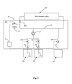
Fig. 1 is a block diagram showing the configuration of a filling device in accordance with a first embodiment of present invention; -
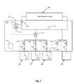
Fig. 2 is a block diagram showing the configuration of a filling device in accordance with a second embodiment of present invention; -
Fig. 3 is a block diagram showing the configuration of a filling device in accordance with a third embodiment of present invention. - Reference will now be made to the drawing figures to describe the preferred embodiments of the present invention in detail. However, the embodiments can not be used to restrict the present invention. Changes such as structure, method and function obviously made to those of ordinary skill in the art are also protected by the present invention.
- Referring to
Fig. 1 , in the first embodiment, afilling device 101 is connected between a mainhydraulic system 200 and afirst fluid resource 301, asecond fluid resource 302, and afluid recycling tank 307. The mainhydraulic system 200 can be any hydraulic systems working with a mixture of fluids, and a geothermal heat pump with a closed loop will be exemplified hereinafter for illustrating the main hydraulic system of present invention. The closed loop is generally buried in the ground with a heat transfer fluid circulated therein for transferring heat stored in the Earth as a heat source in winter and dissipating heat into the ground as a heat sink in summer. - The fluid mixture can be water mixed with glycol to avoid the water to be frozen when the temperature at which the system works is below zero. In this embodiment, the water is a first fluid, and the glycol is a second fluid. The
first fluid resource 301 can be a tank containing pure water or a network of water, and thesecond fluid resource 302 can be a tank containing pure glycol. It would be apparent to those skilled in the art that, in other embodiments, the main hydraulic system can work with a fluid mixture composed of more than two kinds of fluids, and in that case, more tanks respectively containing variant kinds of fluids are needed for filling. - The
filling device 101 can include ahousing 10 for receiving all of components of the device. Afluid mixture circuit 178 is received in thehousing 10. Thefluid mixture circuit 178 can be a main pipe with two ends extending out of thehousing 10 to be connected with the closed loop of the geothermal heat pump for introducing the fluid mixture and circulating it in thefilling device 101 and the geothermal heat pump (namely the main hydraulic system 200). A pressure sensor (PT) 11 is disposed in the housing and connected to thefluid mixture circuit 178 to detect a pressure of the fluid mixture. It is well known that the pressure sensor usually acts as a transducer, and it generates an electrical signal as a function of the pressure imposed by the fluid mixture. A concentration sensor (GS) 12 is also disposed in thehousing 10 and connected to thefluid mixture circuit 178 to detect a concentration of the second fluid, namely the glycol in the fluid mixture. Those skilled in the art can understand that an electronic automatic glycol-concentration measurement sensor can be used as the concentration sensor. In a preferred embodiment, a mainnon-return valve 154 is connected in thefluid mixture circuit 178 to restrict the fluid mixture to circulated in a correct way. - As shown in
Fig. 1 , a firstincoming line 171 and a secondincoming line 172 are connected to thefluid mixture circuit 178 via acommon pump 13. The first and the secondincoming lines housing 10 and immersing in the fluid contained in thewater tank 301 or theglycol tank 302 for introducing the water or the glycol to thefluid mixture circuit 178 under action of thepump 13. Moreover, a first incomingelectric valve 141 is connected in the firstincoming line 171 to be selectively activated on, and a second incomingelectric valve 142 is connected in the secondincoming line 172 to be selectively activated on. The first/second incoming electric valve can be a motorized valve. The incoming lines can be flexible pipes. In a preferred embodiment, a firstnon-return valve 151 and a secondnon-return valve 152 are connected in the first and the secondincoming lines pump 13 to return to the corresponding tank. - A first
outgoing line 177 is connected to thefluid mixture circuit 178, and it has one distal end extending out of thehousing 10 and into thefluid recycling tank 307 for extracting the fluid mixture to therecycling tank 307. Since the glycol is expensive, thefluid recycling tank 307 containing the fluid mixture can be reused. The outgoing line can also be a flexible pipe. A first outgoingelectric valve 147 is connected in the firstoutgoing line 177 to be selectively activated on. Acontroller 16 is disposed in thehousing 10 and electrically connected with thepressure sensor 11, theconcentration sensor 12, thecommon pump 13, the first and the second incomingelectric valve electric valve 147. Thecontroller 16 may be an electronic control system incorporating a Micro Controller Unit (MCU). Of course, thecontroller 16 can also use other types of integrated circuits, such as Application Specific Integrated Circuit (ASIC) and Field Programmable Gate Array (FPGA) etc.. In general, thecontroller 16 real-timely or periodically receives a first signal from the pressure sensor representing the pressure of the fluid mixture and a second signal from the concentration sensor representing the concentration of the glycol in the fluid mixture, thencontroller 16 gets to know if the pressure and the concentration is within the range of target tolerance, or high, or low. Thus, the controller can decide to do nothing, or activate thepump 13 and one or both of the first and the second incomingelectric valves electric valve 147 to open for extraction of the fluid mixture outside. The operation of the filling device in this embodiment will be described in details hereinafter. - Refer to
Fig. 1 , thecontroller 16 receives the first signal from thepressure sensor 11 and the second signal from theconcentration sensor 12 in real time or periodically. If the detected pressure and concentration are both within the range of the target tolerance, the filling device will do nothing. - If the detected pressure exceeds the range of pressure target tolerance, which means the pressure of the fluid mixture is high, then the
controller 16 checks whether the detected concentration is within the range of concentration target tolerance. If the concentration is in the target concentration range, thecontroller 16 only activates the first outgoingelectric valve 147 to open the fluid path defined by the firstoutgoing line 177 to extract the fluid mixture into thefluid recycling tank 307 till the pressure falls back into the target pressure range. If the concentration also exceeds the target concentration range, which means the concentration of glycol in the fluid mixture is high, thecontroller 16 first activates the first outgoingelectric valve 147 to discharge certain amount of the mixture of fluids, then activates thepump 13 and the first incomingelectrical valve 141 to add the water from thewater tank 301 into thefluid mixture circuit 178 till the concentration falls back into the target concentration range. During the period, thecontroller 16 monitors the pressure and concentration and determines how much fluid mixture needs to be extracted and then how much water needs to be added. If the concentration falls below the target concentration range, which means the concentration of glycol in the fluid mixture is low, thecontroller 16 first activates the first outgoingelectric valve 147 to discharge certain amount of the mixture of fluids, then activates thepump 13 and the second incomingelectrical valve 142 to add the glycol from theglycol tank 302 into thefluid mixture circuit 178 till the concentration rises up into the target concentration range. In this case, - If the detected pressure falls below the range of pressure target tolerance, which means the pressure of the fluid mixture becomes low, then the
controller 16 checks whether the detected concentration is within the range of concentration target tolerance. If the concentration is in the target concentration range, thecontroller 16 activates thepump 13, the first and the second incomingelectrical valves fluid mixture circuit 178 till the pressure rises up into the range of pressure target tolerance. If the concentration exceeds the target concentration range, which means the concentration of glycol in the fluid mixture is high, thecontroller 16 can activate thepump 13 and the first incomingelectric valve 141 to only add water into thefluid mixture circuit 178, also, thecontroller 16 can activate thepump 13, the first incomingelectrical valve 141, and the second incomingelectrical valve 142 to add both water and glycol into thefluid mixture circuit 178 till pressure rises up into the pressure target range and the concentration falls back into the target concentration range. If the concentration falls below the target concentration range, which means the concentration of glycol in the fluid mixture is low, thecontroller 16 can activate thepump 13 and the second incomingelectrical valve 142 to only add the glycol into thefluid mixture circuit 178, also, thecontroller 16 can activate thepump 13, the first incomingelectric valve 141, and the second incomingelectric valve 142 to add both water and glycol into thefluid mixture circuit 178 till both the pressure and the concentration rise up into the range of target tolerance. - Referring to
Fig. 2 , which shows a second embodiment of afilling device 102. Compared with the first embodiment, the fillingdevice 102 further includes a thirdincoming line 173 that is connected to thefluid mixture circuit 178 via thecommon pump 13. A third incomingelectric valve 143 is connected in the thirdincoming line 173. This third incomingelectric valve 143 can be a motorized valve, and it is electrically connected to thecontroller 16. Apremixed fluid tank 303 is provided, and the thirdincoming line 173 can extend out of thehousing 10 and has one distal end immersing in the fluid contained in thetank 303. Thispremixed fluid tank 303 can be provided by service companies, and it contains a pre-mixed fluid composed of water and glycol. The premixed fluid may have a concentration of glycol which is the same as that in the fluid mixture of the mainhydraulic system 200. In a preferred embodiment, a thirdnon-return valve 153 is connected in the thirdincoming line 173 to avoid the fluid mixture which has been extracted to return to thetank 303. - The operation of the
filling device 102 is similar to that of thefilling device 101 in the first embodiment, and in the case that the fillingdevice 102 needs to add the fluid mixture only with the target concentration into the mainhydraulic system 200, thepump 13 and the third incomingelectric valve 143 are activated to directly introducing the premixed fluid from thetank 303 into thefluid mixture circuit 178. In this way, the operation becomes easier and the operation time can be reduced. In an alternative embodiment, the premixed fluid can have a concentration of glycol which is higher than the concentration in the fluid mixture of the mainhydraulic system 200. In this case, the premixed fluid can be introduced into the mainhydraulic system 200 together with the water from thewater tank 301 to reach the target concentration. -
Fig. 3 shows a third embodiment of afilling device 103. Compared with the second embodiment, the fillingdevice 103 further includes a secondoutgoing line 174 connected to thefluid mixture circuit 178. The secondoutgoing line 174 has one distal end extending out of thehousing 10 and into thepremixed fluid tank 303. A second outgoingelectric valve 144 is connected in the secondoutgoing line 174. The second outgoingelectric valve 144 can be a motorized valve, and it is electrically connected to thecontroller 16. - In operation, the
controller 16 detects the pressure and the concentration of the fluid mixture in real time or periodically. In case the pressure exceeds the range of target tolerance, thecontroller 16 will compare the detected concentration with a predetermined concentration threshold, and if the detected concentration is equal to or larger than the predetermined threshold, thecontroller 16 will activate the second outgoingelectric valve 144 to extract the fluid mixture into thepremixed fluid tank 303 through the secondoutgoing line 174; if the detected concentration is smaller than the predetermined threshold, thecontroller 16 will activate the first outgoingelectric valve 145 to extract the fluid mixture to thefluid recycling tank 305 through the firstoutgoing line 175. The predetermined concentration threshold may have a value that is larger than that of the target concentration of the fluid mixture. In this way, thefluid recycling tank 305 can be reused in the case that a premixed fluid with a lower concentration is needed, and thefluid premixed tank 303 can be reused in the case that a premixed fluid with a higher concentration is needed. - It is to be understood, however, that even though numerous, characteristics and advantages of the present invention have been set forth in the foregoing description, together with details of the structure and function of the invention, the disclosed is illustrative only, and changes may be made in detail, especially in matters of number, shape, size, and arrangement of parts within the principles of the invention to the full extent indicated by the broadest general meaning of the terms in which the appended claims are expressed.
Claims (10)
- A filling device (101, 102, 103) adapt for filling a hydraulic system (200) with a fluid mixture composed of at least a first fluid and a second fluid, said filling device comprising:a fluid mixture circuit (178) for being connected to the hydraulic system to allow the fluid mixture to circulate therein;a pressure sensor (11) connected to the fluid mixture circuit for detecting a pressure of the fluid mixture in the circuit and generating a first signal representing the pressure;a concentration sensor (12) connected to the fluid mixture circuit for detecting a concentration of the second fluid in the fluid mixture and generating a second signal representing the concentration;a first incoming line (171) connected to the fluid mixture circuit for introducing the first fluid from a first fluid resource (301) to the circuit;a second incoming line (172) connected to the fluid mixture circuit for introducing the second fluid from a second fluid resource (302) to the circuit; anda controller (16) electrically connected with the pressure sensor (11) and the concentration sensor (12) for receiving the first and the second signals and controlling the introduction of the first fluid and/or the second fluid via the first incoming line (171) and/or the second incoming line (172) based on the signals.
- A filling device according to claim 1, further comprising a first outgoing line (177) connected to the fluid mixture circuit for extracting the fluid mixture to a fluid recycling tank (307), and a first outgoing electric valve (147) connected in the first outgoing line; wherein the controller is electrically connected with the first outgoing electric valve to enable said valve to open for extraction of the fluid mixture.
- A filling device according to claim 2, further comprising a third incoming line (173) connected to the fluid mixture circuit for introducing a premixed fluid from a premixed fluid tank (303) to the circuit.
- A filling device according to claim 3, wherein the first, the second and the third incoming lines are connected to the fluid mixture circuit via a common pump (13), and a first, a second, and a third incoming electric valves (141, 142, 143) are connected in the first, the second, and the third incoming lines (171, 172, 173) respectively.
- A filling device according to claim 4, wherein the controller is electrically connected with the pump and the three incoming electric valves for activating the common pump and selectively enabling one or two or all of the three incoming electric valves to open for introducing the first fluid and/or the second fluid and/or the premixed fluid.
- A filling device according to claim 3, further comprising a second outgoing line (174) connected to the fluid mixture circuit for extracting the fluid mixture to the premixed fluid tank (173), and a second outgoing electric valve (144) connected in the second outgoing line; wherein the controller is electrically connected with the second outgoing electric valve to enable said valve to open for extraction of the fluid mixture.
- A filling device according to claim 6, wherein when the controller decides to extract the fluid mixture, the controller first compares the detected concentration with a predetermined concentration threshold, and if the detected concentration is equal to or larger than said predetermined threshold, the controller controls the extraction of the fluid mixture through the second outgoing line, and if the detected concentration is smaller than said predetermined threshold, the controller controls the extraction of the fluid mixture through the first outgoing line.
- A filling device according to claim 1, further comprising a main non-return valve (154) disposed in the fluid mixture circuit to restrict the fluid mixture to circulate in a correct way.
- A filling device according to claim 1, further comprising a first, a second, and a third non-return valves (151, 152, 153) disposed in the first, the second, and the third incoming lines respectively to avoid the first fluid, the second fluid, or the premixed fluid which has been extracted to return to the first fluid resource, the second fluid resource, or the premixed fluid tank respectively.
- A filling device according to claim 1, wherein the first fluid is water, and the second fluid is glycol.
Priority Applications (2)
| Application Number | Priority Date | Filing Date | Title |
|---|---|---|---|
| EP15196412.9A EP3173712B1 (en) | 2015-11-26 | 2015-11-26 | Automatic fluid mixture filling device for hydraulic systems |
| ES15196412T ES2804090T3 (en) | 2015-11-26 | 2015-11-26 | Automatic fluid mixture filling device for hydraulic systems |
Applications Claiming Priority (1)
| Application Number | Priority Date | Filing Date | Title |
|---|---|---|---|
| EP15196412.9A EP3173712B1 (en) | 2015-11-26 | 2015-11-26 | Automatic fluid mixture filling device for hydraulic systems |
Publications (2)
| Publication Number | Publication Date |
|---|---|
| EP3173712A1 true EP3173712A1 (en) | 2017-05-31 |
| EP3173712B1 EP3173712B1 (en) | 2020-04-08 |
Family
ID=54770826
Family Applications (1)
| Application Number | Title | Priority Date | Filing Date |
|---|---|---|---|
| EP15196412.9A Active EP3173712B1 (en) | 2015-11-26 | 2015-11-26 | Automatic fluid mixture filling device for hydraulic systems |
Country Status (2)
| Country | Link |
|---|---|
| EP (1) | EP3173712B1 (en) |
| ES (1) | ES2804090T3 (en) |
Cited By (2)
| Publication number | Priority date | Publication date | Assignee | Title |
|---|---|---|---|---|
| EP3495753A4 (en) * | 2017-10-24 | 2019-09-18 | Mitsubishi Electric Corporation | GEOTHERMAL HEAT PUMP SYSTEM AND METHOD OF CONTROLLING GEOTHERMAL HEAT PUMP SYSTEM |
| CN112415089A (en) * | 2019-08-21 | 2021-02-26 | 格兰富控股联合股份公司 | Pump system |
Citations (6)
| Publication number | Priority date | Publication date | Assignee | Title |
|---|---|---|---|---|
| DE29703044U1 (en) * | 1997-02-20 | 1997-05-28 | Schwörer Haus GmbH & Co., 72764 Reutlingen | Biological space heating |
| US5665242A (en) * | 1995-08-25 | 1997-09-09 | Union Oil Company Of California | Inhibition of silica precipitation |
| DE202010000485U1 (en) * | 2010-03-29 | 2010-07-15 | Würz Energy GmbH | Device for operating a solar thermal system |
| GB2474249A (en) * | 2009-10-07 | 2011-04-13 | Mark Collins | Apparatus for heating a liquid using an exothermic chemical reaction |
| US20110282498A1 (en) * | 2010-05-11 | 2011-11-17 | FLS Solar Technologies, Inc. | Solar thermal data acquisition systems and methods and systems using the same |
| WO2013067570A1 (en) * | 2011-11-11 | 2013-05-16 | Sinclair Knight Merz Pty Limited | Dosing of extracted geothermal fluids |
-
2015
- 2015-11-26 ES ES15196412T patent/ES2804090T3/en active Active
- 2015-11-26 EP EP15196412.9A patent/EP3173712B1/en active Active
Patent Citations (6)
| Publication number | Priority date | Publication date | Assignee | Title |
|---|---|---|---|---|
| US5665242A (en) * | 1995-08-25 | 1997-09-09 | Union Oil Company Of California | Inhibition of silica precipitation |
| DE29703044U1 (en) * | 1997-02-20 | 1997-05-28 | Schwörer Haus GmbH & Co., 72764 Reutlingen | Biological space heating |
| GB2474249A (en) * | 2009-10-07 | 2011-04-13 | Mark Collins | Apparatus for heating a liquid using an exothermic chemical reaction |
| DE202010000485U1 (en) * | 2010-03-29 | 2010-07-15 | Würz Energy GmbH | Device for operating a solar thermal system |
| US20110282498A1 (en) * | 2010-05-11 | 2011-11-17 | FLS Solar Technologies, Inc. | Solar thermal data acquisition systems and methods and systems using the same |
| WO2013067570A1 (en) * | 2011-11-11 | 2013-05-16 | Sinclair Knight Merz Pty Limited | Dosing of extracted geothermal fluids |
Cited By (3)
| Publication number | Priority date | Publication date | Assignee | Title |
|---|---|---|---|---|
| EP3495753A4 (en) * | 2017-10-24 | 2019-09-18 | Mitsubishi Electric Corporation | GEOTHERMAL HEAT PUMP SYSTEM AND METHOD OF CONTROLLING GEOTHERMAL HEAT PUMP SYSTEM |
| CN112415089A (en) * | 2019-08-21 | 2021-02-26 | 格兰富控股联合股份公司 | Pump system |
| CN112415089B (en) * | 2019-08-21 | 2024-05-14 | 格兰富控股联合股份公司 | Pump system |
Also Published As
| Publication number | Publication date |
|---|---|
| ES2804090T3 (en) | 2021-02-03 |
| EP3173712B1 (en) | 2020-04-08 |
Similar Documents
| Publication | Publication Date | Title |
|---|---|---|
| CN104832241B (en) | Engine lubrication control device, system and control method | |
| EA202191291A1 (en) | DRAINAGE SYSTEM AND BUFFER DRAINAGE TANK | |
| CN115853751B (en) | Diaphragm pump control method, device, equipment and storage medium | |
| KR101389410B1 (en) | Real time automatic control system of open ground heat exchanger | |
| RU2016142720A (en) | HYDRAULIC SYSTEM | |
| US8196602B2 (en) | Water distribution system for cold climates | |
| EP3173712B1 (en) | Automatic fluid mixture filling device for hydraulic systems | |
| CN112119220A (en) | Monitoring module and method for identifying operating situations in a wastewater pumping station | |
| WO2021076588A1 (en) | Safety variable frequency drive for preventing over pressurization of a piping network | |
| CN205621818U (en) | Cold system of battery fluid | |
| EP3051243A1 (en) | Arrangement for subsea cooling of electric equipment | |
| CA2910409C (en) | Pump using multi voltage electronics with run dry and over current protection | |
| US20060083624A1 (en) | Subsea fluid delivery system and method | |
| US10080310B2 (en) | Bypassing a removed element in a liquid cooling system | |
| US10954966B2 (en) | Bootstrap accumulator containing integrated bypass valve | |
| US20220137650A1 (en) | Automated Tank Systems and Methods for use in Oil and Gas Extraction Operation | |
| EP2974907A1 (en) | Mobile water cart with water pre-conditioning device | |
| CN202598133U (en) | Automatic oil supply system | |
| CN104847721B (en) | A kind of holding pressure control device and the engineering machinery with it | |
| DE212014000268U1 (en) | Electronic water level switch for automatic control of a pump | |
| CN111288045B (en) | Control method for loading and unloading electromagnetic valve of pump station | |
| RU175922U1 (en) | VEHICLE FEEDING EQUIPMENT CONTROL UNIT IN THE RESERVOIR | |
| CN115326161A (en) | Method for detecting fuel leakage, controller and fuel system | |
| EP3336344A1 (en) | Flow controller | |
| CN205779375U (en) | A kind of fuel oil pump assembly and there is its fuel tank assembly and vehicle |
Legal Events
| Date | Code | Title | Description |
|---|---|---|---|
| PUAI | Public reference made under article 153(3) epc to a published international application that has entered the european phase |
Free format text: ORIGINAL CODE: 0009012 |
|
| STAA | Information on the status of an ep patent application or granted ep patent |
Free format text: STATUS: THE APPLICATION HAS BEEN PUBLISHED |
|
| AK | Designated contracting states |
Kind code of ref document: A1 Designated state(s): AL AT BE BG CH CY CZ DE DK EE ES FI FR GB GR HR HU IE IS IT LI LT LU LV MC MK MT NL NO PL PT RO RS SE SI SK SM TR |
|
| AX | Request for extension of the european patent |
Extension state: BA ME |
|
| STAA | Information on the status of an ep patent application or granted ep patent |
Free format text: STATUS: REQUEST FOR EXAMINATION WAS MADE |
|
| 17P | Request for examination filed |
Effective date: 20171019 |
|
| RBV | Designated contracting states (corrected) |
Designated state(s): AL AT BE BG CH CY CZ DE DK EE ES FI FR GB GR HR HU IE IS IT LI LT LU LV MC MK MT NL NO PL PT RO RS SE SI SK SM TR |
|
| STAA | Information on the status of an ep patent application or granted ep patent |
Free format text: STATUS: EXAMINATION IS IN PROGRESS |
|
| 17Q | First examination report despatched |
Effective date: 20190607 |
|
| REG | Reference to a national code |
Ref country code: DE Ref legal event code: R079 Ref document number: 602015050189 Country of ref document: DE Free format text: PREVIOUS MAIN CLASS: F24J0002080000 Ipc: F24D0019000000 |
|
| GRAP | Despatch of communication of intention to grant a patent |
Free format text: ORIGINAL CODE: EPIDOSNIGR1 |
|
| STAA | Information on the status of an ep patent application or granted ep patent |
Free format text: STATUS: GRANT OF PATENT IS INTENDED |
|
| RIC1 | Information provided on ipc code assigned before grant |
Ipc: F24D 19/00 20060101AFI20191127BHEP Ipc: F24D 3/10 20060101ALI20191127BHEP |
|
| INTG | Intention to grant announced |
Effective date: 20191213 |
|
| GRAS | Grant fee paid |
Free format text: ORIGINAL CODE: EPIDOSNIGR3 |
|
| GRAA | (expected) grant |
Free format text: ORIGINAL CODE: 0009210 |
|
| STAA | Information on the status of an ep patent application or granted ep patent |
Free format text: STATUS: THE PATENT HAS BEEN GRANTED |
|
| AK | Designated contracting states |
Kind code of ref document: B1 Designated state(s): AL AT BE BG CH CY CZ DE DK EE ES FI FR GB GR HR HU IE IS IT LI LT LU LV MC MK MT NL NO PL PT RO RS SE SI SK SM TR |
|
| REG | Reference to a national code |
Ref country code: CH Ref legal event code: EP Ref country code: AT Ref legal event code: REF Ref document number: 1254902 Country of ref document: AT Kind code of ref document: T Effective date: 20200415 |
|
| REG | Reference to a national code |
Ref country code: DE Ref legal event code: R096 Ref document number: 602015050189 Country of ref document: DE |
|
| REG | Reference to a national code |
Ref country code: IE Ref legal event code: FG4D |
|
| REG | Reference to a national code |
Ref country code: NL Ref legal event code: MP Effective date: 20200408 |
|
| REG | Reference to a national code |
Ref country code: LT Ref legal event code: MG4D |
|
| PG25 | Lapsed in a contracting state [announced via postgrant information from national office to epo] |
Ref country code: SE Free format text: LAPSE BECAUSE OF FAILURE TO SUBMIT A TRANSLATION OF THE DESCRIPTION OR TO PAY THE FEE WITHIN THE PRESCRIBED TIME-LIMIT Effective date: 20200408 Ref country code: IS Free format text: LAPSE BECAUSE OF FAILURE TO SUBMIT A TRANSLATION OF THE DESCRIPTION OR TO PAY THE FEE WITHIN THE PRESCRIBED TIME-LIMIT Effective date: 20200808 Ref country code: FI Free format text: LAPSE BECAUSE OF FAILURE TO SUBMIT A TRANSLATION OF THE DESCRIPTION OR TO PAY THE FEE WITHIN THE PRESCRIBED TIME-LIMIT Effective date: 20200408 Ref country code: NO Free format text: LAPSE BECAUSE OF FAILURE TO SUBMIT A TRANSLATION OF THE DESCRIPTION OR TO PAY THE FEE WITHIN THE PRESCRIBED TIME-LIMIT Effective date: 20200708 Ref country code: NL Free format text: LAPSE BECAUSE OF FAILURE TO SUBMIT A TRANSLATION OF THE DESCRIPTION OR TO PAY THE FEE WITHIN THE PRESCRIBED TIME-LIMIT Effective date: 20200408 Ref country code: PT Free format text: LAPSE BECAUSE OF FAILURE TO SUBMIT A TRANSLATION OF THE DESCRIPTION OR TO PAY THE FEE WITHIN THE PRESCRIBED TIME-LIMIT Effective date: 20200817 Ref country code: LT Free format text: LAPSE BECAUSE OF FAILURE TO SUBMIT A TRANSLATION OF THE DESCRIPTION OR TO PAY THE FEE WITHIN THE PRESCRIBED TIME-LIMIT Effective date: 20200408 |
|
| PG25 | Lapsed in a contracting state [announced via postgrant information from national office to epo] |
Ref country code: BG Free format text: LAPSE BECAUSE OF FAILURE TO SUBMIT A TRANSLATION OF THE DESCRIPTION OR TO PAY THE FEE WITHIN THE PRESCRIBED TIME-LIMIT Effective date: 20200708 Ref country code: RS Free format text: LAPSE BECAUSE OF FAILURE TO SUBMIT A TRANSLATION OF THE DESCRIPTION OR TO PAY THE FEE WITHIN THE PRESCRIBED TIME-LIMIT Effective date: 20200408 Ref country code: HR Free format text: LAPSE BECAUSE OF FAILURE TO SUBMIT A TRANSLATION OF THE DESCRIPTION OR TO PAY THE FEE WITHIN THE PRESCRIBED TIME-LIMIT Effective date: 20200408 Ref country code: LV Free format text: LAPSE BECAUSE OF FAILURE TO SUBMIT A TRANSLATION OF THE DESCRIPTION OR TO PAY THE FEE WITHIN THE PRESCRIBED TIME-LIMIT Effective date: 20200408 |
|
| PG25 | Lapsed in a contracting state [announced via postgrant information from national office to epo] |
Ref country code: AL Free format text: LAPSE BECAUSE OF FAILURE TO SUBMIT A TRANSLATION OF THE DESCRIPTION OR TO PAY THE FEE WITHIN THE PRESCRIBED TIME-LIMIT Effective date: 20200408 |
|
| REG | Reference to a national code |
Ref country code: DE Ref legal event code: R097 Ref document number: 602015050189 Country of ref document: DE |
|
| PG25 | Lapsed in a contracting state [announced via postgrant information from national office to epo] |
Ref country code: SM Free format text: LAPSE BECAUSE OF FAILURE TO SUBMIT A TRANSLATION OF THE DESCRIPTION OR TO PAY THE FEE WITHIN THE PRESCRIBED TIME-LIMIT Effective date: 20200408 Ref country code: EE Free format text: LAPSE BECAUSE OF FAILURE TO SUBMIT A TRANSLATION OF THE DESCRIPTION OR TO PAY THE FEE WITHIN THE PRESCRIBED TIME-LIMIT Effective date: 20200408 Ref country code: IT Free format text: LAPSE BECAUSE OF FAILURE TO SUBMIT A TRANSLATION OF THE DESCRIPTION OR TO PAY THE FEE WITHIN THE PRESCRIBED TIME-LIMIT Effective date: 20200408 Ref country code: DK Free format text: LAPSE BECAUSE OF FAILURE TO SUBMIT A TRANSLATION OF THE DESCRIPTION OR TO PAY THE FEE WITHIN THE PRESCRIBED TIME-LIMIT Effective date: 20200408 Ref country code: CZ Free format text: LAPSE BECAUSE OF FAILURE TO SUBMIT A TRANSLATION OF THE DESCRIPTION OR TO PAY THE FEE WITHIN THE PRESCRIBED TIME-LIMIT Effective date: 20200408 Ref country code: RO Free format text: LAPSE BECAUSE OF FAILURE TO SUBMIT A TRANSLATION OF THE DESCRIPTION OR TO PAY THE FEE WITHIN THE PRESCRIBED TIME-LIMIT Effective date: 20200408 |
|
| REG | Reference to a national code |
Ref country code: ES Ref legal event code: FG2A Ref document number: 2804090 Country of ref document: ES Kind code of ref document: T3 Effective date: 20210203 |
|
| PLBE | No opposition filed within time limit |
Free format text: ORIGINAL CODE: 0009261 |
|
| STAA | Information on the status of an ep patent application or granted ep patent |
Free format text: STATUS: NO OPPOSITION FILED WITHIN TIME LIMIT |
|
| PG25 | Lapsed in a contracting state [announced via postgrant information from national office to epo] |
Ref country code: PL Free format text: LAPSE BECAUSE OF FAILURE TO SUBMIT A TRANSLATION OF THE DESCRIPTION OR TO PAY THE FEE WITHIN THE PRESCRIBED TIME-LIMIT Effective date: 20200408 Ref country code: SK Free format text: LAPSE BECAUSE OF FAILURE TO SUBMIT A TRANSLATION OF THE DESCRIPTION OR TO PAY THE FEE WITHIN THE PRESCRIBED TIME-LIMIT Effective date: 20200408 |
|
| 26N | No opposition filed |
Effective date: 20210112 |
|
| PG25 | Lapsed in a contracting state [announced via postgrant information from national office to epo] |
Ref country code: SI Free format text: LAPSE BECAUSE OF FAILURE TO SUBMIT A TRANSLATION OF THE DESCRIPTION OR TO PAY THE FEE WITHIN THE PRESCRIBED TIME-LIMIT Effective date: 20200408 |
|
| PG25 | Lapsed in a contracting state [announced via postgrant information from national office to epo] |
Ref country code: MC Free format text: LAPSE BECAUSE OF FAILURE TO SUBMIT A TRANSLATION OF THE DESCRIPTION OR TO PAY THE FEE WITHIN THE PRESCRIBED TIME-LIMIT Effective date: 20200408 |
|
| REG | Reference to a national code |
Ref country code: CH Ref legal event code: PL |
|
| PG25 | Lapsed in a contracting state [announced via postgrant information from national office to epo] |
Ref country code: LU Free format text: LAPSE BECAUSE OF NON-PAYMENT OF DUE FEES Effective date: 20201126 |
|
| REG | Reference to a national code |
Ref country code: BE Ref legal event code: MM Effective date: 20201130 |
|
| PG25 | Lapsed in a contracting state [announced via postgrant information from national office to epo] |
Ref country code: CH Free format text: LAPSE BECAUSE OF NON-PAYMENT OF DUE FEES Effective date: 20201130 Ref country code: LI Free format text: LAPSE BECAUSE OF NON-PAYMENT OF DUE FEES Effective date: 20201130 |
|
| PG25 | Lapsed in a contracting state [announced via postgrant information from national office to epo] |
Ref country code: IE Free format text: LAPSE BECAUSE OF NON-PAYMENT OF DUE FEES Effective date: 20201126 |
|
| PG25 | Lapsed in a contracting state [announced via postgrant information from national office to epo] |
Ref country code: TR Free format text: LAPSE BECAUSE OF FAILURE TO SUBMIT A TRANSLATION OF THE DESCRIPTION OR TO PAY THE FEE WITHIN THE PRESCRIBED TIME-LIMIT Effective date: 20200408 Ref country code: MT Free format text: LAPSE BECAUSE OF FAILURE TO SUBMIT A TRANSLATION OF THE DESCRIPTION OR TO PAY THE FEE WITHIN THE PRESCRIBED TIME-LIMIT Effective date: 20200408 Ref country code: CY Free format text: LAPSE BECAUSE OF FAILURE TO SUBMIT A TRANSLATION OF THE DESCRIPTION OR TO PAY THE FEE WITHIN THE PRESCRIBED TIME-LIMIT Effective date: 20200408 |
|
| PG25 | Lapsed in a contracting state [announced via postgrant information from national office to epo] |
Ref country code: MK Free format text: LAPSE BECAUSE OF FAILURE TO SUBMIT A TRANSLATION OF THE DESCRIPTION OR TO PAY THE FEE WITHIN THE PRESCRIBED TIME-LIMIT Effective date: 20200408 |
|
| PG25 | Lapsed in a contracting state [announced via postgrant information from national office to epo] |
Ref country code: GR Free format text: LAPSE BECAUSE OF FAILURE TO SUBMIT A TRANSLATION OF THE DESCRIPTION OR TO PAY THE FEE WITHIN THE PRESCRIBED TIME-LIMIT Effective date: 20200408 Ref country code: BE Free format text: LAPSE BECAUSE OF NON-PAYMENT OF DUE FEES Effective date: 20201130 |
|
| PGFP | Annual fee paid to national office [announced via postgrant information from national office to epo] |
Ref country code: GB Payment date: 20221025 Year of fee payment: 8 Ref country code: FR Payment date: 20221125 Year of fee payment: 8 Ref country code: ES Payment date: 20221201 Year of fee payment: 8 Ref country code: DE Payment date: 20221025 Year of fee payment: 8 Ref country code: AT Payment date: 20221027 Year of fee payment: 8 |
|
| REG | Reference to a national code |
Ref country code: AT Ref legal event code: UEP Ref document number: 1254902 Country of ref document: AT Kind code of ref document: T Effective date: 20200408 |
|
| REG | Reference to a national code |
Ref country code: DE Ref legal event code: R119 Ref document number: 602015050189 Country of ref document: DE |
|
| REG | Reference to a national code |
Ref country code: AT Ref legal event code: MM01 Ref document number: 1254902 Country of ref document: AT Kind code of ref document: T Effective date: 20231126 |
|
| PG25 | Lapsed in a contracting state [announced via postgrant information from national office to epo] |
Ref country code: AT Free format text: LAPSE BECAUSE OF NON-PAYMENT OF DUE FEES Effective date: 20231126 |
|
| GBPC | Gb: european patent ceased through non-payment of renewal fee |
Effective date: 20231126 |
|
| PG25 | Lapsed in a contracting state [announced via postgrant information from national office to epo] |
Ref country code: AT Free format text: LAPSE BECAUSE OF NON-PAYMENT OF DUE FEES Effective date: 20231126 |
|
| PG25 | Lapsed in a contracting state [announced via postgrant information from national office to epo] |
Ref country code: DE Free format text: LAPSE BECAUSE OF NON-PAYMENT OF DUE FEES Effective date: 20240601 |
|
| PG25 | Lapsed in a contracting state [announced via postgrant information from national office to epo] |
Ref country code: GB Free format text: LAPSE BECAUSE OF NON-PAYMENT OF DUE FEES Effective date: 20231126 |
|
| PG25 | Lapsed in a contracting state [announced via postgrant information from national office to epo] |
Ref country code: FR Free format text: LAPSE BECAUSE OF NON-PAYMENT OF DUE FEES Effective date: 20231130 |
|
| PG25 | Lapsed in a contracting state [announced via postgrant information from national office to epo] |
Ref country code: GB Free format text: LAPSE BECAUSE OF NON-PAYMENT OF DUE FEES Effective date: 20231126 Ref country code: FR Free format text: LAPSE BECAUSE OF NON-PAYMENT OF DUE FEES Effective date: 20231130 Ref country code: DE Free format text: LAPSE BECAUSE OF NON-PAYMENT OF DUE FEES Effective date: 20240601 |
|
| REG | Reference to a national code |
Ref country code: ES Ref legal event code: FD2A Effective date: 20250107 |
|
| PG25 | Lapsed in a contracting state [announced via postgrant information from national office to epo] |
Ref country code: ES Free format text: LAPSE BECAUSE OF NON-PAYMENT OF DUE FEES Effective date: 20231127 |
|
| PG25 | Lapsed in a contracting state [announced via postgrant information from national office to epo] |
Ref country code: ES Free format text: LAPSE BECAUSE OF NON-PAYMENT OF DUE FEES Effective date: 20231127 |