EP3173647A1 - Constant velocity universal joint - Google Patents
Constant velocity universal joint Download PDFInfo
- Publication number
- EP3173647A1 EP3173647A1 EP15824214.9A EP15824214A EP3173647A1 EP 3173647 A1 EP3173647 A1 EP 3173647A1 EP 15824214 A EP15824214 A EP 15824214A EP 3173647 A1 EP3173647 A1 EP 3173647A1
- Authority
- EP
- European Patent Office
- Prior art keywords
- shaft
- peripheral surface
- boot
- constant velocity
- cylindrical member
- Prior art date
- Legal status (The legal status is an assumption and is not a legal conclusion. Google has not performed a legal analysis and makes no representation as to the accuracy of the status listed.)
- Granted
Links
- 230000002093 peripheral effect Effects 0.000 claims abstract description 141
- 238000005299 abrasion Methods 0.000 claims abstract description 43
- 238000006073 displacement reaction Methods 0.000 claims abstract description 11
- 239000000314 lubricant Substances 0.000 claims description 8
- 230000005540 biological transmission Effects 0.000 claims description 7
- 239000000463 material Substances 0.000 description 18
- 229920005989 resin Polymers 0.000 description 11
- 239000011347 resin Substances 0.000 description 11
- 229920001971 elastomer Polymers 0.000 description 10
- 239000005060 rubber Substances 0.000 description 9
- 239000004519 grease Substances 0.000 description 8
- 239000011248 coating agent Substances 0.000 description 6
- 238000000576 coating method Methods 0.000 description 6
- 230000004323 axial length Effects 0.000 description 5
- 229910052751 metal Inorganic materials 0.000 description 5
- 239000002184 metal Substances 0.000 description 5
- XEEYBQQBJWHFJM-UHFFFAOYSA-N Iron Chemical compound [Fe] XEEYBQQBJWHFJM-UHFFFAOYSA-N 0.000 description 4
- 230000000694 effects Effects 0.000 description 4
- -1 polytetrafluoroethylene Polymers 0.000 description 4
- 230000006872 improvement Effects 0.000 description 3
- 230000009467 reduction Effects 0.000 description 3
- 230000003746 surface roughness Effects 0.000 description 3
- 229920002725 thermoplastic elastomer Polymers 0.000 description 3
- 229920005992 thermoplastic resin Polymers 0.000 description 3
- 239000004696 Poly ether ether ketone Substances 0.000 description 2
- 230000002159 abnormal effect Effects 0.000 description 2
- 230000032683 aging Effects 0.000 description 2
- 229910052782 aluminium Inorganic materials 0.000 description 2
- XAGFODPZIPBFFR-UHFFFAOYSA-N aluminium Chemical compound [Al] XAGFODPZIPBFFR-UHFFFAOYSA-N 0.000 description 2
- 230000015556 catabolic process Effects 0.000 description 2
- 238000006731 degradation reaction Methods 0.000 description 2
- 150000001993 dienes Chemical class 0.000 description 2
- 229910052742 iron Inorganic materials 0.000 description 2
- 229920002530 polyetherether ketone Polymers 0.000 description 2
- 238000007789 sealing Methods 0.000 description 2
- 238000004804 winding Methods 0.000 description 2
- 229930040373 Paraformaldehyde Natural products 0.000 description 1
- 239000004952 Polyamide Substances 0.000 description 1
- 239000004962 Polyamide-imide Substances 0.000 description 1
- 239000004698 Polyethylene Substances 0.000 description 1
- 239000004642 Polyimide Substances 0.000 description 1
- 239000004734 Polyphenylene sulfide Substances 0.000 description 1
- 230000015572 biosynthetic process Effects 0.000 description 1
- 230000008859 change Effects 0.000 description 1
- 230000008602 contraction Effects 0.000 description 1
- 239000000806 elastomer Substances 0.000 description 1
- 230000001747 exhibiting effect Effects 0.000 description 1
- 229920001973 fluoroelastomer Polymers 0.000 description 1
- 238000010438 heat treatment Methods 0.000 description 1
- 238000005461 lubrication Methods 0.000 description 1
- 230000007246 mechanism Effects 0.000 description 1
- 238000000034 method Methods 0.000 description 1
- 238000012986 modification Methods 0.000 description 1
- 230000004048 modification Effects 0.000 description 1
- CLNYHERYALISIR-UHFFFAOYSA-N nona-1,3-diene Chemical compound CCCCCC=CC=C CLNYHERYALISIR-UHFFFAOYSA-N 0.000 description 1
- 229920002647 polyamide Polymers 0.000 description 1
- 229920002312 polyamide-imide Polymers 0.000 description 1
- 229920000573 polyethylene Polymers 0.000 description 1
- 229920001721 polyimide Polymers 0.000 description 1
- 229920006324 polyoxymethylene Polymers 0.000 description 1
- 229920000069 polyphenylene sulfide Polymers 0.000 description 1
- 229920001343 polytetrafluoroethylene Polymers 0.000 description 1
- 239000004810 polytetrafluoroethylene Substances 0.000 description 1
- 239000000843 powder Substances 0.000 description 1
- 230000002265 prevention Effects 0.000 description 1
- 238000005096 rolling process Methods 0.000 description 1
- 229920003002 synthetic resin Polymers 0.000 description 1
- 239000000057 synthetic resin Substances 0.000 description 1
- BFKJFAAPBSQJPD-UHFFFAOYSA-N tetrafluoroethene Chemical group FC(F)=C(F)F BFKJFAAPBSQJPD-UHFFFAOYSA-N 0.000 description 1
- 238000003878 thermal aging Methods 0.000 description 1
- 229920001187 thermosetting polymer Polymers 0.000 description 1
Images







Classifications
-
- F—MECHANICAL ENGINEERING; LIGHTING; HEATING; WEAPONS; BLASTING
- F16—ENGINEERING ELEMENTS AND UNITS; GENERAL MEASURES FOR PRODUCING AND MAINTAINING EFFECTIVE FUNCTIONING OF MACHINES OR INSTALLATIONS; THERMAL INSULATION IN GENERAL
- F16D—COUPLINGS FOR TRANSMITTING ROTATION; CLUTCHES; BRAKES
- F16D3/00—Yielding couplings, i.e. with means permitting movement between the connected parts during the drive
- F16D3/16—Universal joints in which flexibility is produced by means of pivots or sliding or rolling connecting parts
- F16D3/20—Universal joints in which flexibility is produced by means of pivots or sliding or rolling connecting parts one coupling part entering a sleeve of the other coupling part and connected thereto by sliding or rolling members
- F16D3/22—Universal joints in which flexibility is produced by means of pivots or sliding or rolling connecting parts one coupling part entering a sleeve of the other coupling part and connected thereto by sliding or rolling members the rolling members being balls, rollers, or the like, guided in grooves or sockets in both coupling parts
- F16D3/223—Universal joints in which flexibility is produced by means of pivots or sliding or rolling connecting parts one coupling part entering a sleeve of the other coupling part and connected thereto by sliding or rolling members the rolling members being balls, rollers, or the like, guided in grooves or sockets in both coupling parts the rolling members being guided in grooves in both coupling parts
-
- F—MECHANICAL ENGINEERING; LIGHTING; HEATING; WEAPONS; BLASTING
- F16—ENGINEERING ELEMENTS AND UNITS; GENERAL MEASURES FOR PRODUCING AND MAINTAINING EFFECTIVE FUNCTIONING OF MACHINES OR INSTALLATIONS; THERMAL INSULATION IN GENERAL
- F16D—COUPLINGS FOR TRANSMITTING ROTATION; CLUTCHES; BRAKES
- F16D3/00—Yielding couplings, i.e. with means permitting movement between the connected parts during the drive
- F16D3/84—Shrouds, e.g. casings, covers; Sealing means specially adapted therefor
- F16D3/843—Shrouds, e.g. casings, covers; Sealing means specially adapted therefor enclosed covers
- F16D3/845—Shrouds, e.g. casings, covers; Sealing means specially adapted therefor enclosed covers allowing relative movement of joint parts due to the flexing of the cover
-
- F—MECHANICAL ENGINEERING; LIGHTING; HEATING; WEAPONS; BLASTING
- F16—ENGINEERING ELEMENTS AND UNITS; GENERAL MEASURES FOR PRODUCING AND MAINTAINING EFFECTIVE FUNCTIONING OF MACHINES OR INSTALLATIONS; THERMAL INSULATION IN GENERAL
- F16D—COUPLINGS FOR TRANSMITTING ROTATION; CLUTCHES; BRAKES
- F16D3/00—Yielding couplings, i.e. with means permitting movement between the connected parts during the drive
- F16D3/16—Universal joints in which flexibility is produced by means of pivots or sliding or rolling connecting parts
- F16D3/20—Universal joints in which flexibility is produced by means of pivots or sliding or rolling connecting parts one coupling part entering a sleeve of the other coupling part and connected thereto by sliding or rolling members
- F16D3/22—Universal joints in which flexibility is produced by means of pivots or sliding or rolling connecting parts one coupling part entering a sleeve of the other coupling part and connected thereto by sliding or rolling members the rolling members being balls, rollers, or the like, guided in grooves or sockets in both coupling parts
- F16D3/223—Universal joints in which flexibility is produced by means of pivots or sliding or rolling connecting parts one coupling part entering a sleeve of the other coupling part and connected thereto by sliding or rolling members the rolling members being balls, rollers, or the like, guided in grooves or sockets in both coupling parts the rolling members being guided in grooves in both coupling parts
- F16D2003/22303—Details of ball cages
-
- F—MECHANICAL ENGINEERING; LIGHTING; HEATING; WEAPONS; BLASTING
- F16—ENGINEERING ELEMENTS AND UNITS; GENERAL MEASURES FOR PRODUCING AND MAINTAINING EFFECTIVE FUNCTIONING OF MACHINES OR INSTALLATIONS; THERMAL INSULATION IN GENERAL
- F16D—COUPLINGS FOR TRANSMITTING ROTATION; CLUTCHES; BRAKES
- F16D3/00—Yielding couplings, i.e. with means permitting movement between the connected parts during the drive
- F16D3/16—Universal joints in which flexibility is produced by means of pivots or sliding or rolling connecting parts
- F16D3/20—Universal joints in which flexibility is produced by means of pivots or sliding or rolling connecting parts one coupling part entering a sleeve of the other coupling part and connected thereto by sliding or rolling members
- F16D3/22—Universal joints in which flexibility is produced by means of pivots or sliding or rolling connecting parts one coupling part entering a sleeve of the other coupling part and connected thereto by sliding or rolling members the rolling members being balls, rollers, or the like, guided in grooves or sockets in both coupling parts
- F16D3/223—Universal joints in which flexibility is produced by means of pivots or sliding or rolling connecting parts one coupling part entering a sleeve of the other coupling part and connected thereto by sliding or rolling members the rolling members being balls, rollers, or the like, guided in grooves or sockets in both coupling parts the rolling members being guided in grooves in both coupling parts
- F16D2003/22323—Attachments to the shaft of the inner joint member whereby the attachments are distanced from the core
-
- F—MECHANICAL ENGINEERING; LIGHTING; HEATING; WEAPONS; BLASTING
- F16—ENGINEERING ELEMENTS AND UNITS; GENERAL MEASURES FOR PRODUCING AND MAINTAINING EFFECTIVE FUNCTIONING OF MACHINES OR INSTALLATIONS; THERMAL INSULATION IN GENERAL
- F16D—COUPLINGS FOR TRANSMITTING ROTATION; CLUTCHES; BRAKES
- F16D3/00—Yielding couplings, i.e. with means permitting movement between the connected parts during the drive
- F16D3/16—Universal joints in which flexibility is produced by means of pivots or sliding or rolling connecting parts
- F16D3/20—Universal joints in which flexibility is produced by means of pivots or sliding or rolling connecting parts one coupling part entering a sleeve of the other coupling part and connected thereto by sliding or rolling members
- F16D3/22—Universal joints in which flexibility is produced by means of pivots or sliding or rolling connecting parts one coupling part entering a sleeve of the other coupling part and connected thereto by sliding or rolling members the rolling members being balls, rollers, or the like, guided in grooves or sockets in both coupling parts
- F16D3/223—Universal joints in which flexibility is produced by means of pivots or sliding or rolling connecting parts one coupling part entering a sleeve of the other coupling part and connected thereto by sliding or rolling members the rolling members being balls, rollers, or the like, guided in grooves or sockets in both coupling parts the rolling members being guided in grooves in both coupling parts
- F16D2003/22326—Attachments to the outer joint member, i.e. attachments to the exterior of the outer joint member or to the shaft of the outer joint member
-
- F—MECHANICAL ENGINEERING; LIGHTING; HEATING; WEAPONS; BLASTING
- F16—ENGINEERING ELEMENTS AND UNITS; GENERAL MEASURES FOR PRODUCING AND MAINTAINING EFFECTIVE FUNCTIONING OF MACHINES OR INSTALLATIONS; THERMAL INSULATION IN GENERAL
- F16D—COUPLINGS FOR TRANSMITTING ROTATION; CLUTCHES; BRAKES
- F16D2300/00—Special features for couplings or clutches
- F16D2300/12—Mounting or assembling
-
- F—MECHANICAL ENGINEERING; LIGHTING; HEATING; WEAPONS; BLASTING
- F16—ENGINEERING ELEMENTS AND UNITS; GENERAL MEASURES FOR PRODUCING AND MAINTAINING EFFECTIVE FUNCTIONING OF MACHINES OR INSTALLATIONS; THERMAL INSULATION IN GENERAL
- F16D—COUPLINGS FOR TRANSMITTING ROTATION; CLUTCHES; BRAKES
- F16D3/00—Yielding couplings, i.e. with means permitting movement between the connected parts during the drive
- F16D3/16—Universal joints in which flexibility is produced by means of pivots or sliding or rolling connecting parts
- F16D3/20—Universal joints in which flexibility is produced by means of pivots or sliding or rolling connecting parts one coupling part entering a sleeve of the other coupling part and connected thereto by sliding or rolling members
- F16D3/202—Universal joints in which flexibility is produced by means of pivots or sliding or rolling connecting parts one coupling part entering a sleeve of the other coupling part and connected thereto by sliding or rolling members one coupling part having radially projecting pins, e.g. tripod joints
- F16D3/205—Universal joints in which flexibility is produced by means of pivots or sliding or rolling connecting parts one coupling part entering a sleeve of the other coupling part and connected thereto by sliding or rolling members one coupling part having radially projecting pins, e.g. tripod joints the pins extending radially outwardly from the coupling part
- F16D3/2055—Universal joints in which flexibility is produced by means of pivots or sliding or rolling connecting parts one coupling part entering a sleeve of the other coupling part and connected thereto by sliding or rolling members one coupling part having radially projecting pins, e.g. tripod joints the pins extending radially outwardly from the coupling part having three pins, i.e. true tripod joints
-
- F—MECHANICAL ENGINEERING; LIGHTING; HEATING; WEAPONS; BLASTING
- F16—ENGINEERING ELEMENTS AND UNITS; GENERAL MEASURES FOR PRODUCING AND MAINTAINING EFFECTIVE FUNCTIONING OF MACHINES OR INSTALLATIONS; THERMAL INSULATION IN GENERAL
- F16D—COUPLINGS FOR TRANSMITTING ROTATION; CLUTCHES; BRAKES
- F16D3/00—Yielding couplings, i.e. with means permitting movement between the connected parts during the drive
- F16D3/84—Shrouds, e.g. casings, covers; Sealing means specially adapted therefor
- F16D3/843—Shrouds, e.g. casings, covers; Sealing means specially adapted therefor enclosed covers
-
- Y—GENERAL TAGGING OF NEW TECHNOLOGICAL DEVELOPMENTS; GENERAL TAGGING OF CROSS-SECTIONAL TECHNOLOGIES SPANNING OVER SEVERAL SECTIONS OF THE IPC; TECHNICAL SUBJECTS COVERED BY FORMER USPC CROSS-REFERENCE ART COLLECTIONS [XRACs] AND DIGESTS
- Y10—TECHNICAL SUBJECTS COVERED BY FORMER USPC
- Y10S—TECHNICAL SUBJECTS COVERED BY FORMER USPC CROSS-REFERENCE ART COLLECTIONS [XRACs] AND DIGESTS
- Y10S464/00—Rotary shafts, gudgeons, housings, and flexible couplings for rotary shafts
- Y10S464/904—Homokinetic coupling
- Y10S464/905—Torque transmitted via radially extending pin
-
- Y—GENERAL TAGGING OF NEW TECHNOLOGICAL DEVELOPMENTS; GENERAL TAGGING OF CROSS-SECTIONAL TECHNOLOGIES SPANNING OVER SEVERAL SECTIONS OF THE IPC; TECHNICAL SUBJECTS COVERED BY FORMER USPC CROSS-REFERENCE ART COLLECTIONS [XRACs] AND DIGESTS
- Y10—TECHNICAL SUBJECTS COVERED BY FORMER USPC
- Y10S—TECHNICAL SUBJECTS COVERED BY FORMER USPC CROSS-REFERENCE ART COLLECTIONS [XRACs] AND DIGESTS
- Y10S464/00—Rotary shafts, gudgeons, housings, and flexible couplings for rotary shafts
- Y10S464/904—Homokinetic coupling
- Y10S464/906—Torque transmitted via radially spaced balls
Definitions
- the present invention relates to a constant velocity universal joint, which is to be mounted to a power transmission system for an automobile or various types of industrial machines, e.g. , a drive shaft or a propeller shaft of an automobile, and which includes a boot configured to prevent entry of a foreign matter from outside the joint and leakage of a lubricant from inside the joint.
- Constant velocity universal joints to be used as, for example, means for transmitting a rotational force from an engine of an automobile to wheels at constant velocity are classified into such two types as a fixed type constant velocity universal joint and a plunging type constant velocity universal joint.
- the two types of constant velocity universal joints have structure capable of transmitting rotational torque at constant velocity even when two shafts, namely, a drive shaft and a driven shaft are coupled to each other to form an operating angle.
- a drive shaft configured to transmit power from an engine of an automobile to a driving wheel needs to cope with angular displacement and axial displacement due to a change in relative positional relationship between the engine and the wheel. Therefore, in general, a plunging type constant velocity universal joint configured to allow both the angular displacement and the axial displacement is mounted on an engine side (inboard side), and a fixed type constant velocity universal joint configured to allow only the angular displacement is mounted to a driving wheel side (outboard side).
- the both constant velocity universal joints are connected to each other with a shaft.
- the fixed type constant velocity universal joint includes an outer joint member 123, an inner joint member 126, a plurality of balls 127, and a cage 128.
- the outer joint member 123 has a plurality of track grooves 122 formed in a radially inner surface 121 at equal intervals in a circumferential direction and along an axial direction.
- the inner joint member 126 has a plurality of track grooves 125 formed in a radially outer surface 124 at equal intervals in a circumferential direction and along the axial direction to be paired with the track grooves 122 of the outer joint member 123.
- the plurality of balls 127 are interposed between the track grooves 122 of the outer joint member 123 and the track grooves 125 of the inner joint member 126 and configured to transmit torque.
- the cage 128 is interposedbetween the radially inner surface 121 of the outer joint member 123 and the radially outer surface 124 of the inner joint member 126 and configured to retain the balls 127.
- a female spline 129 is formed in a radially inner surface of a shaft hole of the inner joint member 126
- a male spline 131 is formed in an end portion of a shaft 130 to be fitted into the shaft hole of the inner joint member 126.
- a circlip 132 is mounted to the end portion of the shaft 130. With this, the shaft 130 is prevented from being coming off.
- the outer joint member 123 includes a mouth section 123a having the plurality of track grooves 122 formed in the radially inner surface 121 and a stem section (shaft section) 123b projecting from a bottom wall of the mouth section 123a.
- the plunging type constant velocity universal joint includes an outer joint member 141, a tripod member 143, and rollers 144.
- the outer joint member 141 has three track grooves 140 being formed along an inner periphery thereof and extending in an axial direction and has roller guide surfaces 140a respectively opposed to inner walls of the track grooves 140.
- the tripod member 143 has three journal 142 and serves as an inner joint member.
- the rollers 144 are rotatably supported by the journal 142 and rollably placed in the track grooves 140 of the outer joint member 141, and serve as torque transmission units. In this case, the rollers 144 are externally fitted through interposition of a plurality of rollers 145 arranged on radially outer surfaces of the journal 142 along a circumferential direction.
- the outer joint member 141 includes a mouth section 141a and a stem section 141b, which are integrally formed.
- the mouth section 141a has a cup shape which is opened at one end thereof.
- the three track grooves 140 extending in the axial direction are formed in a radially inner surface of the mouth section 141a.
- the tripod member 143 includes aboss 146 and the journal 142.
- the journal 142 project radially at three equiangular positions in the circumferential direction of the boss.
- a female spline 148 is formed in a radially inner surface of the boss 146.
- An end portion of the shaft 150 on the inboard side is inserted to the boss 146, and a male spline 149 formed in the end portion of the shaft 150 is fitted to the female spline 148 of the boss 146.
- a circlip 152 is mounted to the end portion of the shaft 150. With this, the shaft 150 is prevented from coming off.
- a boot 160 made of rubber or resin is mounted between the outer joint member 123 (141) of the constant velocity universal joint and the shaft 130 (150) extending from the inner joint member 126 (143) to close an opening portion of the outer joint member 123 (141) with the boot 160.
- the boot 160 includes a large-diameter end portion 160a, a small-diameter end portion 160b, and a bellows portion 160c.
- the large-diameter end portion 160a is fastened and fixed by a boot clamp 161 to an outer peripheral surface of the opening portion of the outer joint member 123 (141) of the constant velocity universal joint.
- the small-diameter end portion 160b is fastened and fixed by a boot clamp 162 to an outer peripheral surface of the shaft 130 (150) extending from the inner joint member 126 (143) of the constant velocity universal joint.
- the bellows portion 160c connects the large-diameter end portion 160a and the small-diameter end portion 160b.
- the bellows portion 160c has peak portions and root portions which are formed alternately and continuously and is reduced in diameter from the large-diameter end portion 160a to the small-diameter end portion 160b so as to be expandable and contractible.
- the constant velocity universal joint has a function to rotate while taking an operation angle. Further, the plunging type constant velocity universal joint has a function to rotate while sliding in the axial direction. Therefore, various proposals have hitherto been made in order to secure durability, such as abrasion resistance and fatigue resistance, of the boot.
- an inner diameter of the root portions of the boot is increased.
- the inner peripheral surfaces of the root portions of the boot are formed into a shape which achieves high resistance against abrasion.
- the surface roughness of the outer peripheral surface of the shaft is reduced.
- Patent Literature 3 a component for reducing abrasion or abnormal sound is added to a material of the boot.
- Patent Literature 4 on a surface of the boot made of a diene-based rubber material, a synthetic resin containing polytetrafluoroethylene powder is arranged as a discontinuous coating. According to Patent Literature 4, such discontinuous coating is arranged to stably achieve a low friction property and abrasion resistance in the surface.
- the bellows portion is divided into a portion closer to a large-diameter mounting part, a portion closer to a small-diameter mounting part, and a center portion, and the rigidities of those parts are differentiated.
- the relationship of the rigidities of the parts is set to be the center portion>the portion closer to the large-diameter mounting part>the portion closer to the small-diameter mounting part.
- the diameter of the mountain portion and the diameter of the root portion are limited.
- the boot is deformed to follow the movement.
- a phase in a direction of taking the operating angle hereinafter referred to as "contraction side"
- inner surfaces of the root portions are more liable to be brought into contact with the shaft.
- the outer peripheral surface of the shaft has a lead surface formed by turning. Therefore, when the inner peripheral surfaces of the root portions of the bellows portion are brought into contact with the outer peripheral surface of the shaft, abrasion is more liable to occur in the inner peripheral surfaces of the root portions of the bellows portion. As a result, the durability of the boot is degraded, and lifetime of the boot is shortened.
- any of the constant velocity universal joints disclosed in Patent Literature 1 and Patent Literature 2 cannot avoid the contact of the innerperipheral surfaces of the root portions of the boot with respect to the outer peripheral surface of the shaft.
- the inner peripheral surfaces of the root portions of the boot and the outer peripheral surface of the shaft may have relative movement in the axial direction and in the circumferential direction.
- friction may occur between the inner peripheral surfaces of the root portions of the boot and the outer peripheral surface of the shaft.
- the friction may cause the abrasion in the inner peripheral surfaces of the root portions of the boot.
- surface processing with respect to the shaft is required, which may cause difficulty in reducing cost.
- Patent Literature 3 improvement in abrasion resistance and reduction in abnormal sound can be expected. However, it does not provide a sufficient measure for the interference and friction between the root portions of the boot bellows portion and the shaft, and rather causes degradation in fatigue resistance or aging resistance and degradation in the sealing property at the large-diameter end portion and the small-diameter end portion.
- Patent Literature 4 even when such discontinuous coating is applied to an inner surface of the boot, there is difficulty in obtaining sufficient abrasion resistance in the inner surfaces of the root portions.
- Patent Literature 5 and Patent Literature 6 elaborated boot shapes have been proposed. However, in any of those cases, the measure for improvement of the abrasion resistance in the inner surfaces of the root portions is not sufficient, and the compactness of the entire boot is poor.
- the present invention has been proposed in view of the above-mentioned problems, and has an object to provide a constant velocity universal joint which may reliably suppress abrasion in an inner peripheral surface of a boot due to a contact between the inner peripheral surface of the boot and an outer peripheral surface of a shaft.
- a constant velocity universal joint comprising: an outer joint member having an opening portion at one end thereof; an inner joint member configured to transmit torque while allowing angular displacement with respect to the outer joint member through a torque transmission member; a boot closing the opening portion of the outer joint member, the boot having end portions which are fastened and fixed to a mounting part of the outer joint member and a mounting part of a shaft member extending from the inner joint member; and an intermediate member configured to reduce abrasion due to friction caused by relative movement between an outer peripheral surf ace of the shaft member and an inner peripheral surface of the boot, the intermediate member being arranged at a part of the outer peripheral surface of the shaft member where at least the inner peripheral surface of the boot is brought into contact when the shaft member takes an operating angle with respect to the outer joint member.
- the relative movement is a relative movement in an axial direction and in the circumferential direction of the constant velocity universal joint.
- the intermediate member configured to reduce abrasion due to friction caused by the relative movement between the outer peripheral surface of the shaft member and the inner peripheral surface of the boot is arranged at a part of the outer peripheral surface of the shaft member where at least the inner peripheral surface of the boot is brought into contact when the shaft member takes the operating angle with respect to the outer joint member.
- the intermediate member according to the present invention which is configured to reduce the abrasion due to the friction caused by the relative movement, comprise a sliding bearing.
- the intermediate member configured to reduce the friction can be constructed with a simple unit.
- the amount of relative movement between the inner peripheral surface of the boot and the outer peripheral surface of the sliding bearing can be set smaller than the amount of relative movement between the inner peripheral surface of the boot and the outer peripheral surface of the shaft member. That is, the friction of the boot with respect to the sliding bearing can be set smaller than the friction of the boot with respect to the shaft member, thereby being capable of reliably suppressing the abrasion in the inner peripheral surface of the boot caused by the friction.
- the intermediate member according to the present invention which is configured to reduce the abrasion due to the friction caused by the relative movement, comprise a plurality of sliding bearings independently arranged next to each other along the axial direction.
- a contact area per sliding bearing with respect to the outer peripheral surface of the shaft member is reduced.
- the sliding bearing becomes more likely to slide on the outer peripheral surface of the shaft member. Therefore, the amount of relative movement between the inner peripheral surface of the boot and the outer peripheral surface of the sliding bearing can be further reduced.
- the respective sliding bearings independently slide on the outer peripheral surface of the shaft member. Therefore, the amount of relative movement of the inner peripheral surface of the boot with respect to the sliding bearing can be further suppressed.
- the intermediate member according to the present invention which is configured to reduce the abrasion due to the friction caused by the relative movement, be formed of a cylindrical member configured to cover the outer peripheral surface of the shaft member, and that the cylindrical member as a pair of end portions, which are capable of being joined to each other, be formed along the axial direction at least at one location of the cylindrical member in the circumferential direction.
- the intermediate member configured to reduce the friction caused by the relative movement can easily be assembled to the shaft member. That is, the pair of end portions are joined to each other under a state in which the shaft member is received in the cylindrical member having the pair of end portions separated apart, and then assembly of the cylindrical member with respect to the shaft member can be completed.
- the intermediate member configured to reduce the friction caused by the relative movement may be formed of the cylindrical member configured to cover the outer peripheral surface of the shaft member, and the cylindrical member may be movable with respect to the shaft member in the circumferential direction and in the axial direction.
- the cylindrical member have an axial slit formed between both axial ends thereof.
- the cylindrical member can be increased in diameter so that an inner diameter dimension thereof is set larger than a maximum outer diameter dimension at the shaft end part of the shaft member. Further, the cylindrical member can be increased in diameter so that a width dimension of the axial slit in the circumferential direction becomes larger than the outer diameter dimension at the part of the shaft member where the inner peripheral surface of the boot is brought into contact.
- the cylindrical member When the cylindrical member is to be mounted to the part where the inner peripheral surface of the boot is brought into contact, the cylindrical member may be reduced in diameter to the inner diameter dimension enabling the movement with respect to the shaft member in the circumferential direction and in the axial direction.
- the cylindrical member may have the inner diameter dimension set smaller than the part where the inner peripheral surface of the boot is brought into contact.
- the cylindrical member may be increased in diameter to the inner diameter enabling the movement with respect to the shaft member in the circumferential direction and the axial direction.
- a lubricant sealed inside the joint be interposed between the inner peripheral surface of the cylindrical member and the outer peripheral surface of the shaft member.
- the intermediate member configured to reduce the abrasion due to the friction caused by the relative movement (in the axial direction and in the circumferential direction) between the outer peripheral surface of the shaft member and the inner peripheral surface of the boot is arranged at a part of the outer peripheral surface of the shaft member where at least the inner peripheral surface of the boot is brought into contact when the shaft member takes the operating angle with respect to the outer joint member.
- a constant velocity universal joint according to embodiments of the present invention is hereinafter described in detail.
- a Rzeppa type constant velocity universal joint being a fixed type constant velocity universal joint which allows only angular displacement is exemplified.
- the present invention is also applicable to other fixed type constant velocity universal joint, e.g., an undercut-free type constant velocity universal joint.
- the present invention is also applicable to the plunging type constant velocity universal joints such as the tripod type, cross-groove type, and double offset type constant velocity universal joints which allow both the angular displacement and the axial displacement.
- the present invention is applicable to constant velocity universal joints to be mounted to a drive shaft and a propeller shaft of an automobile.
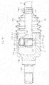
- FIG. 1 is an illustration of a constant velocity universal joint under a state in which an operating angle is 0° according to a first embodiment.
- the constant velocity universal joint comprises, as main components, an outer joint member 10, an inner joint member 20, a plurality of balls 30, and a cage 40.
- the outer joint member 10 has a cup shape.
- Track grooves 11 having an arc shape and extending in an axial direction are formed in a spherical inner peripheral surface 12 at a plurality of locations in a circumferential direction.
- the inner joint member 20 has track grooves 21 each having an arc shape.
- the track grooves 21 are formed in a spherical outer peripheral surface 22 at a plurality of locations in the circumferential direction and paired with the track grooves 11 of the outer joint member 10 to extend in the axial direction.
- the balls 30 are interposed between the track grooves 11 of the outer joint member 10 and the track grooves 21 of the inner joint member 20 and serve as torque transmission members.
- the cage 40 is arranged between the spherical inner peripheral surface 12 of the outer joint member 10 and the spherical outer peripheral surface 22 of the inner joint member 20 and configured to retain the balls 30 with pockets formed at equal intervals in the circumferential direction.
- a shaft end part 51 of a shaft 50 being a shaft member is connected to a shaft hole of the inner joint member 20 through spline fitting so that torque can be transmitted.
- the constant velocity universal joint of this type has structure in which a bellows boot 60 made of, for example, resin or rubber is mounted between the outer joint member 10 and the shaft 50 in order to prevent leakage of a lubricant, e.g. , grease sealed inside the joint and to prevent entry of a foreign matter from outside the joint.
- a circlip 55 is mounted to an end portion of the shaft 50 to prevent the shaft 50 from coming off.
- the outer joint member 10 comprises a mouth section 10a and a stem section (shaft section) 10b.
- the mouth section 10a has the plurality of track grooves 11 formed in a radially inner surface.
- the stem section 10b projects from a bottom wall of the mouth section 10a.
- lubricity is secured at slidingparts inside the joint, that is, sliding parts at components comprising the outer joint member 10, the inner joint member 20, the balls 30, and the cage 40.
- the above-mentioned boot 60 comprises a large-diameter end portion 61, a small-diameter end portion 62, and a bellows portion 65.
- the large-diameter end portion 61 is fastened and fixed by a boot clamp 71 to an outer peripheral surface of an opening portion being a mounting part of the outer joint member 10.
- the small-diameter end portion 62 is fastened and fixed by a boot clamp 72 to an outer peripheral surface of a mounting part 52 of the shaft 50 extending from the inner joint member 20.
- the bellows portion 65 connects the large-diameter end portion 61 and the small-diameter end portion 62.
- the bellows portion 65 has peak portions 63 and root portions 64, which are formed alternately and continuously, and is reduced in diameter from the large-diameter end portion 61 to the small-diameter end portion 62 so as to be expandable and contractible.
- the shaft 50 described above comprises the shaft end part 51, the mounting part 52, and the intermediate part 53.
- the shaft end part 51 is press-fitted to the shaft hole of the inner joint member 20.
- the mounting part 52 bears the small-diameter end portion 62 of the boot 60 fastened and fixed thereto.
- the intermediate part 53 is located between the shaft end part 51 and the mounting part 52.
- the intermediate part 53 of the shaft 50 has an outer diameter smaller than outer diameters of the shaft end part 51 and the mounting part 52, and has a smooth outer peripheral surface extending along the axial direction.
- the bellows portion 65 of the boot 60 is arranged on the outer side of the intermediate part 53 of the shaft 50.
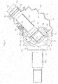
- FIG. 2 is an illustration of a state in which the constant velocity universal joint takes an operating angle.
- the constant velocity universal joint takes the operating angle
- one side of the boot 60 upper side in FIG. 2
- the inner peripheral surfaces of the root portions 64 of the bellows portion 65 become more liable to be brought into contact with the outer peripheral surface of the shaft 50.
- there is relative movement between the inner peripheral surfaces of the root portions 64 of the bellows portion 65 and the outer peripheral surface of the shaft 50 see FIG. 1 ). Therefore, friction is generated between the inner peripheral surfaces of the root portions 64 of the bellows portion 65 and the outer peripheral surface of the shaft 50.
- an intermediate member which is configured to reduce the abrasion due to the friction caused by the relative movement between the inner peripheral surfaces of the root portions 64 of the bellows portion 65 and the outer peripheral surface of the intermediate part 53 of the shaft 50, at a part of the outer peripheral surface of the shaft 50 where at least the inner peripheral surfaces of the root portions 64 of the bellows portion 65 are brought into contact, that is, at the outer peripheral surface of the intermediate part 53 of the shaft 50 when the constant velocity universal joint takes the operating angle.
- a sliding bearing 80 is effective because the intermediate member configured to reduce the friction caused by the relative movement can be constructed with a simple unit.
- the sliding bearing 80 is mounted to extend over a substantially entire length of the intermediate part 53 of the shaft 50 so as to cover the intermediate part 53. Further, the sliding bearing 80 is mounted under a state in which a clearance is formed with respect to the intermediate part 53 of the shaft 50. Thus, co-rotation with the shaft 50 can be avoided.
- the sliding bearing 80 is made of resin having a self-lubricating property, the abrasion in the inner peripheral surfaces of the root portions 64 of the bellows portion 6 5 can easily be reduced. Further, a coating film may be formed on the outer peripheral surface of the sliding bearing 80. The formation of the coating film is effective because the abrasion due to the contact between the outer peripheral surface of the sliding bearing 80 and the inner peripheral surfaces of the root portions 64 of the bellows portion 65 is suppressed.
- the material forming the sliding bearing 80 for example, resin having the self-lubricating property may comprise polyimide, polyamide-imide, polyetheretherketone (PEEK), a fluororesin (tetrafluoroethylene), a fluororesin-based elastomer (fluororubber), polyphenylene sulfide, polyoxymethylene, polyamide, polyethylene, and the like.
- the material of the sliding bearing 80 may be a material other than the resin having the self-lubricating property. However, when metal or the like having a hardness higher than that of resin is to be used, it is desired to form the coating film on the outer peripheral surface of the sliding bearing 80 to suppress the abrasion.
- the sliding bearing 80 having the above-mentioned configuration mounted to the intermediate part 53 of the shaft 50, when the constant velocity universal joint takes the operating angle, the inner peripheral surfaces of the root portions 64 of the bellows portion 65 of the boot 60 are not brought into direct contact with the outer peripheral surface of the intermediate part 53 of the shaft50whichishardenedbyquenching. That is, theslidingbearing 80 is interposed between the inner peripheral surfaces of the root portions 64 of the bellows portion 65 and the outer peripheral surface of the intermediate part 53 of the shaft 50.
- the amount of relative movement between the inner peripheral surfaces of the root portions 64 of the bellows portion 65 and the outer peripheral surface of the sliding bearing 80 can be set smaller than the amount of relative movement between the inner peripheral surfaces of the root portions 64 of the bellows portion 65 and the outer peripheral surface of the intermediate part 53 of the shaft 50. That is, the friction of the boot 60 with respect to the sliding bearing 80 can be set smaller than the friction of the boot 60 with respect to the shaft 50. Thus, the abrasion in the inner peripheral surfaces of the root portions 64 of the bellows portion 65 due to the friction can reliably be suppressed.
- the abrasion in the root portions 64 of the bellows portion 65 is not affected by the surface roughness of the outer peripheral surface of the intermediate part 53 of the shaft 50, and surface processing with respect to the shaft 50 is not required.
- a PV value which is obtained by multiplying the maximum contact surface pressure P by the sliding speed V, be 3,000 [MPa ⁇ mm/s] or less.
- the constant velocity universal joint of FIG. 1 and FIG. 2 has structure in which one sliding bearing 80 is arranged on the outer peripheral surface of the intermediate part 53 of the shaft 50.
- a plurality of sliding bearings 81 may be arranged on the outer peripheral surface of the intermediate part 53 of the shaft 50.
- Those sliding bearings 81 are independently arranged next to each other along the axial direction on the outer peripheral surface of the intermediate part 53 of the shaft 50.
- the material, function, and actions and effects of the sliding bearings 81 are the same as those of the one sliding bearing 80 used in the constant velocity universal joint of FIG. 1 and FIG. 2 , and hence redundant description thereof is omitted.
- the contact area per sliding bearing with respect to the outer peripheral surface of the intermediate part 53 of the shaft 50 is reduced.
- the sliding bearing 81 becomes more likely to slide on the outer peripheral surface of the intermediate part 53 of the shaft 50. Therefore, the friction caused by the relative movement between the inner peripheral surfaces of the root portions 64 of the bellows portion 65 of the boot 60 and the outer peripheral surface of the sliding bearing 81 can further be reduced.
- the sliding bearings 81 independently slide on the outer peripheral surface of the intermediate part 53 of the shaft 50.
- the friction caused by the relative movement of the inner peripheral surfaces of the root portions 64 of the bellows portion 65 with respect to the sliding bearings can further be suppressed.
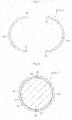
- the sliding bearings 80 and 81 to be used for the constant velocity universal joints illustrated in FIG. 1 to FIG. 4 may have structure in which a pair of end portions that can be joined to each other (engagement portions 84 and 85 described later) formed at least at one location in the circumferential direction thereof to extend along the axial direction as illustrated in FIG. 5 and FIG. 7 . With such structure, the sliding bearings 80 or 81 can easily be mounted to the intermediate part 53 of the shaft 50.
- the sliding bearing 80 or 81 of FIG. 5 is an example in which the end portions that can be joined to each other are arranged at one location.
- the sliding bearing 80 or 81 has structure in which two half-split parts 83 connected to each other by a connecting portion 82 are openable and closable, and in which engagement portions 84 and 85 that can be joined to each other are formed at the respective end portions of the half-split parts 83.
- the connecting portion 82 has a cut in an inner periphery thereof to allow the two half-split parts 83 to be openable and closable.
- One engagement portion 84 has a radially inner side projecting in the circumferential direction and has a shape with a thickness that increases from a base end to a distal end.
- Another engagement portion 85 has a radially outer side projecting in the circumferential direction and has a shape with a thickness that increases from a base end to a distal end.
- the intermediate part 53 of the shaft 50 is received inside thereof under a state in which the two half-split parts 83 are opened. Then, as illustrated in FIG. 6 , one engagement portion 84 and another engagement portion 85 are joined to each other. Thus, assembly to the intermediate part 53 of the shaft 50 is completed.
- Each of one engagement portion 84 and another engagement portion 85 has a shape with a thickness that increases from the base end to the distal end. Thus, the engagement portions 84 and 85 are prevented from being disengaged after assembly, thereby being capable of maintaining a state of being rigidly joined to each other.
- the sliding bearing 80 or 81 of FIG. 7 is an example in which the end portions that can be joined to each other are arranged at two locations, and has structure in which engagement portions 87 and 88 are formed at each of both end portions of two half-split parts 86 which are independently separated.
- One engagement portion 87 of each of the half-split parts 86 has a radially inner side projecting in the circumferential direction and has a shape with a thickness that increases from a base end to a distal end.
- Another engagement portion 88 has a radially outer side projecting in the circumferential direction and has a shape with a thickness that increases from a base end to a distal end.
- the intermediate part 53 of the shaft 50 is arranged between the two half-split parts 86. Then, as illustrated in FIG. 8 , the engagement portions 87 and 88 located at both end portions of one half-split part 86 and the engagement portions 87 and 88 located at both end portions of another half-split part 86 are joined to each other. Thus, assembly to the intermediate part 53 of the shaft 50 is completed.
- Each of one engagement portion 87 and another engagement portion 88 has a shape with a thickness that increases from the base end to the distal end. Thus, the engagement portions 87 and 88 are prevented from being disengaged after assembly, thereby being capable of maintaining a state of being rigidly joined to each other.
- the sliding bearing 80 or 81 is used as the intermediate member configured to reduce the friction caused by the relative movement.
- the present invention is not limited thereto.
- a rolling bearing can also be used as another intermediate member configured to reduce the friction caused by the relative movement.
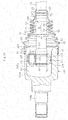
- FIG. 9 is an illustration of a third embodiment of the present invention.
- the intermediate member configured to reduce the friction caused by the relative movement comprises a cylindrical member 100 configured to cover the outer peripheral surface of the shaft 50 being the shaft member.
- the cylindrical member 100 is movable with respect to the shaft 50 in the circumferential direction (direction of the arrow A) and in the axial direction (direction of the arrow B).
- the cylindrical member 100 has a straight slit 101 extending along the axial direction to reach both axial ends thereof. That is, the cylindrical member 100 has a circular cross-sectional shape in which a cutout portion is formed in part. Therefore, the cylindrical member 100 is increased in diameter by increasing a width dimension of the slit 101, and then is fitted to the intermediate part 53 of the shaft 50.
- the slit 101 is widened as indicated by the arrows A1 and A2 of FIG. 10 to increase an inner diameter dimension of the cylindrical member 100 to be larger than the outer diameter dimension of the shaft end part 51 of the shaft 50.
- the cylindrical member 100 is fitted to the intermediate part 53 of the shaft 50 through the shaft end part 51 of the shaft 50.
- the slit 101 may further be widened to increase the circumferential width of the slit 101 to be larger than the diameter of the intermediate part 53 of the shaft 50.
- the cylindrical member 100 is fitted to the intermediate part 53 of the shaft 50. In this fitted state, a diameter-increasing force applied to the cylindrical member 100 is released.
- a restoring force of the cylindrical member 100 reduces the diameter to be restored to the diameter in a free state. Further, it is not always necessary that the cylindrical member 100 be restored to the original diameter after releasing the diameter-increasing force under a state of being increased in diameter to be larger than the outer diameter dimension of the shaft end part 51 of the shaft 50. It is only necessary that the cylindrical member 100 be restored to the free state of conforming to the intermediate part 53 of the shaft 50 through application of a diameter-reducing force under a state of being fitted to the intermediate part 53.
- the inner diameter dimension of the cylindrical member 100 in the free state is set larger than the outer diameter dimension of the intermediate part 53 of the shaft 50 by approximately from 0.1 mm to 1 mm. Further, the axial length of the cylindrical member 100 is set smaller than that of the intermediate part 53, and is set to a dimension that allows the amount of sliding of the root portions 64 of the bellows portion 65 of the boot 60 along the axis center direction in contact with the cylindrical member 100 when the constant velocity universal joint is rotated while taking any operating angle.
- the material of the cylindrical member 100 may be metal, resin, or rubber.
- the inner diameter of the cylindrical member 100 is increased when the cylindrical member 100 is mounted to the shaft 50, and hence the material needs to have a property of allowing deformation and enabling restoration, after mounting, to the dimension satisfying the above-mentioned conditions for mounting to the shaft 50.
- the metal there may be used iron or aluminum.
- the cylindrical member 100 made of metal there is difficulty in increasing the diameter when the thickness is excessively large. Thus, there is a fear in that the operability in restoration to the original free state may be degraded or in that unnecessary partial deformation may occur in the cylindrical member 100, which is not desired. Therefore, in the case of using iron or aluminum, the thickness is set to from 0.01 mm to 0.5 mm.
- the thickness dimension In the case of using resin or rubber, a degree of freedom in the thickness dimension is higher than that in the case of using metal. However, when the thickness dimension is set larger, the operating angle which may cause the start of contact with the root portions 64 of the boot 60 becomes smaller. Therefore, the influence on the deformation state and fatigue of the boot 60 is concerned. Thus, in the case of using resin or rubber, it is preferred that the thickness dimension be 1 mm or less.
- the material of resin there may be applied thermosetting resin, thermoplastic resin, thermoplastic elastomer, or the like. However, the thermoplastic resin or thermoplastic elastomer is desired in consideration of mountability to the shaft 50.
- thermoplastic resin even when a hard material is selected, mounting to the shaft 50 can be performed under a state in which the material is softened through heating. In the case of the thermoplastic elastomer, mounting to the shaft 50 can easily be performed at normal temperature.
- the rubber a generally known material such as diene-based rubber or non-diene-based rubber can be used.
- a lubricant (grease) for lubrication is sealed in the constant velocity universal joint.
- the inner diameter dimension of the cylindrical member 100 is set larger than the outer diameter dimension of the intermediate part 53 by approximately from 0.1 mm to 1 mm.
- a slight clearance is formed between the shaft 50 and the cylindrical member 100, and the grease is interposed in the clearance.
- the axial length of the intermediate part 53 of the shaft 50 is set smaller, which is different from the constant velocity universal joint illustrated in FIG. 9 .
- the axial length of the boot 60 to be mounted is set smaller. That is, the bellows portion 65 of the boot 60 illustrated in FIG. 9 comprises six peak portions 63 and five root portions 64, whereas the bellows portion 65 of the boot 60 illustrated in FIG. 11 comprises four peak portions 63 and three root portions 64.
- the cylindrical member 100 is formed of a short cylindrical body to correspond to the axial length of the intermediate part 53 of the shaft 50. Also in this case, the width dimension of the slit 101 (see FIG. 10 ) is increased to increase the cylindrical member 100 in diameter, and the cylindrical member 100 is fitted to the intermediate part 53 of the shaft 50. Further, the inner diameter dimension of the cylindrical member 100 in the free state is set larger than the outer diameter dimension of the intermediate part 53 of the cylindrical member 100 by approximately from 0.1 mm to 1 mm. Thus, the cylindrical member 100 is movable with respect to the shaft in the circumferential direction (direction of the arrow A) and in the axial direction (direction of the arrow B) .
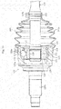
- FIG. 12 is an illustration of a plunging type constant velocity universal joint of a tripod type as the constant velocity universal joint.
- the plunging type constant velocity universal joint comprises an outer joint member 106, a tripod member 108, and rollers 109.
- the outer joint member 106 has three track grooves 105 being formed along an inner periphery thereof and extending in the axial direction and has roller guide surfaces 105a respectively opposed to inner walls of the track grooves 105.
- the tripod member 108 has three journal 107 and serves as an inner joint member.
- the rollers 109 are rotatably supported by the journal 107 and rollably placed in the track grooves 105 of the outer joint member 106 and serve as torque transmission units. In this case, the rollers 109 are externally fitted through interposition of a plurality of rollers 110 arranged on radially outer surfaces of the journal 107 along the circumferential direction.
- the outer joint member 106 comprises a mouth section 106a and a stem section 106b, which are integrally formed.
- the mouth section 106a has a cup shape which is opened at one end thereof.
- the three track grooves 105 extending in the axial direction are formed in a radially inner surface of the mouth section 106a.
- the tripod member 108 comprises a boss 111 and the journal 107.
- the journal 107 project radially at three equiangular positions in the circumferential direction of the boss 111.
- a female spline 112 is formed in a radially inner surface of the boss 111.
- An end portion of the shaft 50 is inserted to the boss 111, and a male spline 113 formed in the end portion of the shaft 50 is fitted to the female spline 112 of the boss 111.
- the shaft 50 and the tripod member 108 are connected to each other so that torque can be transmitted.
- a circlip 56 is mounted to the end portion of the shaft 50. With this, the shaft 50 is prevented from coming off.
- the bellows portion 65 of the boot 60 comprises eight peak portions 63 and seven root portions 64. Further, four root portions 64 on the small-diameter end portion 62 side are arranged close to the intermediate part 53 of the shaft 50. Thus, the cylindrical member 100 to be externally fitted to the intermediate part 53 of the shaft 50 has the axial length corresponding to those four root portions 64.
- the inner diameter dimension of the cylindrical member 100 in the free state is set larger than the outer diameter dimension of the intermediate part 53 of the shaft 50 by approximately from 0.1 mm to 1 mm.
- the cylindrical member 100 is movable with respect to the shaft in the circumferential direction (direction of the arrow A) and in the axial direction (direction of the arrow B).
- the inner diameter dimension thereof may be set smaller than the outer diameter dimension of the intermediate part 53 of the shaft 50 or set larger by approximately from 0.1 mm to 1 mm.
- the cylindrical member 100 When the cylindrical member 100 is to be mounted to the intermediate part 53 of the shaft 50, the cylindrical member 100 is increased in diameter and fitted to the intermediate part 53 of the shaft 50. Also in this case, the cylindrical member 100 is movable with respect to the shaft 50 in the circumferential direction (direction of the arrow A) and in the axial direction (direction of the arrow B). Further, the grease enters through the slit 101 to be interposed between the intermediate part 53 of the shaft 50 and the cylindrical member 100.
- the inner diameter dimension of the cylindrical member 100 in the mounted state is set equal to the outer diameter dimension of the intermediate part 53 of the shaft 50 or set larger by approximately from 0.1 mm to 1 mm. However, even when the inner diameter dimension of the cylindrical member 100 is set equal to the outer diameter dimension of the intermediate part 53 of the shaft 50, it may be substantially slightly larger because the grease is interposed between the cylindrical member 100 and the intermediate part 53.
- the width dimension (clearance dimension) T of the slit 101 When the width dimension (clearance dimension) T of the slit 101 is excessively large, there is a fear in that the root portions 64 of the boot 60 are brought into contact with the shaft 50 through the slit 101. Therefore, it is preferred that the width dimension (clearance dimension) T of the slit 101 be set to 2 mm or less.
- FIG. 14A is an illustration of the slit 101 with a straight shape formed along the axial direction as in FIG. 10 .
- FIG. 14B is an illustration of the slit 101 with a convex and concave fitting teeth shape.
- FIG. 14C is an illustration of the slit 101 with a triangular teeth shape.
- FIG. 14D is an illustration of the slit 101 with a shape inclined with respect to the axial direction and curved.
- FIG. 14E is an illustration of the slit 101 with a waveform teeth shape.
- FIG. 14F is an illustration of the cylindrical member formed by spirally winding a belt-like body. In FIG. 14F , the slit 101 is formed with a spiral shape.
- the axial slit 101 is formed to extend between both axial ends. Therefore, the cylindrical member 100 can easilybe increased or reduced, thereby enabling quick and reliable operations of mounting and removing.
- the cylindrical member 100 can be increased in diameter so that the inner diameter dimension thereof is set larger than the maximum outer diameter dimension of the shaft member (shaft 50).
- the cylindrical member 100 may be reduced in diameter to the inner diameter dimension enabling the movement with respect to the shaft member (shaft 50) in the circumferential direction and in the axial direction.
- the cylindrical member 100 may have an inner diameter dimension set smaller than the part (intermediate part 53 of the shaft 50) where the inner peripheral surface (root portions 64) of the boot 60 is brought into contact.
- the cylindrical member 100 When the cylindrical member 100 is to be mounted to the part (intermediate part 53 of the shaft 50) where the inner peripheral surface (root portions 64) of the boot 60 is brought into contact, the cylindrical member 100 may be increased in diameter to the inner diameter dimension enabling the movement with respect to the shaft member (shaft 50) in the circumferential direction and in the axial direction. Therefore, the cylindrical member 100 has an extremely simple structure, thereby contributing to improvement in productivity and reduction of cost. Further, the slit 101 is not limited to have a straight shape extending along the axial direction, and may have various shapes as illustrated in FIG. 14B to FIG. 14F . As a result, a degree of freedom in design is high, and productivity is excellent.
- the lubricant (grease) sealed inside the joint is interposed between the inner peripheral surface of the cylindrical member 100 and the outer peripheral surface of the shaft member (shaft 50).
- the cylindrical member 100 can smoothly move on the shaft 50.
- the root portions 64 of the boot 60 are brought into contact with the cylindrical member 100, and a force is applied to the cylindrical member 100.
- the cylindrical member 100 moves along with the movement of the root portions 64 of the boot 60 brought into contact with the cylindrical member 100. Therefore, relative movement does not occur between the root portions 64 and the cylindrical member 100, thereby preventing abrasion in the root portions 64.
- any existing (known and used in public) boot having hitherto been used for the constant velocity universal joint can be used.
- the present invention even when the root portions 64 of the boot 60 are brought into contact with the cylindrical member 100, abrasion does not occur in the root portions 64 of the boot 60.
- the root diameter of the root portions 64 can be set smaller. Therefore, a compact design with a small boot outer diameter can be achieved.
- the material of the boot 60 is not limited, and various materials are applicable.
- materials utilizing the characteristic of the present application are applicable, such as materials which exhibit excellent fatigue resistance or thermal aging resistance even when the abrasion resistance is degraded as compared to that of the related-art materials. As a result, the number of options is increased.
- the present invention is applicable to fixed type constant velocity universal joints and plunging type constant velocity universal joints. It is effective for prevention of abrasion in the root portions 64 of the boot 60 when the fixed type constant velocity universal joint takes a large operating angle. Thus, the boot 60 can be compact. Even in the plunging type constant velocity universal joint, the peak and root diameters of the boot 60 can be designed to be extremely small. Thus, the boot 60 can be designed with compactness. In any specification, application of the present application is very effective.
- a tripod type there may be employed a single roller type or a double roller type.
Landscapes
- Engineering & Computer Science (AREA)
- General Engineering & Computer Science (AREA)
- Mechanical Engineering (AREA)
- Sealing Devices (AREA)
- Diaphragms And Bellows (AREA)
- Shafts, Cranks, Connecting Bars, And Related Bearings (AREA)
Abstract
Description
- The present invention relates to a constant velocity universal joint, which is to be mounted to a power transmission system for an automobile or various types of industrial machines, e.g. , a drive shaft or a propeller shaft of an automobile, and which includes a boot configured to prevent entry of a foreign matter from outside the joint and leakage of a lubricant from inside the joint.
- Constant velocity universal joints to be used as, for example, means for transmitting a rotational force from an engine of an automobile to wheels at constant velocity are classified into such two types as a fixed type constant velocity universal joint and a plunging type constant velocity universal joint. The two types of constant velocity universal joints have structure capable of transmitting rotational torque at constant velocity even when two shafts, namely, a drive shaft and a driven shaft are coupled to each other to form an operating angle.
- A drive shaft configured to transmit power from an engine of an automobile to a driving wheel needs to cope with angular displacement and axial displacement due to a change in relative positional relationship between the engine and the wheel. Therefore, in general, a plunging type constant velocity universal joint configured to allow both the angular displacement and the axial displacement is mounted on an engine side (inboard side), and a fixed type constant velocity universal joint configured to allow only the angular displacement is mounted to a driving wheel side (outboard side). The both constant velocity universal joints are connected to each other with a shaft.
- As illustrated in
FIG. 15 , the fixed type constant velocity universal joint includes an outerjoint member 123, an innerjoint member 126, a plurality ofballs 127, and acage 128. The outerjoint member 123 has a plurality oftrack grooves 122 formed in a radiallyinner surface 121 at equal intervals in a circumferential direction and along an axial direction. The innerjoint member 126 has a plurality oftrack grooves 125 formed in a radiallyouter surface 124 at equal intervals in a circumferential direction and along the axial direction to be paired with thetrack grooves 122 of theouter joint member 123. The plurality ofballs 127 are interposed between thetrack grooves 122 of theouter joint member 123 and thetrack grooves 125 of theinner joint member 126 and configured to transmit torque. Thecage 128 is interposedbetween the radiallyinner surface 121 of theouter joint member 123 and the radiallyouter surface 124 of theinner joint member 126 and configured to retain theballs 127. - Further, a
female spline 129 is formed in a radially inner surface of a shaft hole of theinner joint member 126, and amale spline 131 is formed in an end portion of ashaft 130 to be fitted into the shaft hole of theinner joint member 126. Thus, when the end portion of theshaft 130 is fitted into the shaft hole of theinner joint member 126, thefemale spline 129 of theinner joint member 126 and themale spline 131 of theshaft 130 are fitted so that torque can be transmitted. Acirclip 132 is mounted to the end portion of theshaft 130. With this, theshaft 130 is prevented from being coming off. Theouter joint member 123 includes amouth section 123a having the plurality oftrack grooves 122 formed in the radiallyinner surface 121 and a stem section (shaft section) 123b projecting from a bottom wall of themouth section 123a. - As illustrated in
FIG. 16 , the plunging type constant velocity universal joint includes anouter joint member 141, atripod member 143, androllers 144. The outerjoint member 141 has threetrack grooves 140 being formed along an inner periphery thereof and extending in an axial direction and hasroller guide surfaces 140a respectively opposed to inner walls of thetrack grooves 140. Thetripod member 143 has threejournal 142 and serves as an inner joint member. Therollers 144 are rotatably supported by thejournal 142 and rollably placed in thetrack grooves 140 of theouter joint member 141, and serve as torque transmission units. In this case, therollers 144 are externally fitted through interposition of a plurality ofrollers 145 arranged on radially outer surfaces of thejournal 142 along a circumferential direction. - The outer
joint member 141 includes amouth section 141a and astem section 141b, which are integrally formed. Themouth section 141a has a cup shape which is opened at one end thereof. The threetrack grooves 140 extending in the axial direction are formed in a radially inner surface of themouth section 141a. Thetripod member 143 includes aboss 146 and thejournal 142. Thejournal 142 project radially at three equiangular positions in the circumferential direction of the boss. - A
female spline 148 is formed in a radially inner surface of theboss 146. An end portion of theshaft 150 on the inboard side is inserted to theboss 146, and amale spline 149 formed in the end portion of theshaft 150 is fitted to thefemale spline 148 of theboss 146. With this, theshaft 150 and thetripod member 143 are fitted to each other so that torque can be transmitted. Acirclip 152 is mounted to the end portion of theshaft 150. With this, theshaft 150 is prevented from coming off. - In the fixed type constant velocity universal joint or the plunging type constant velocity universal joint, in order to prevent leakage of a lubricant such as grease sealed inside the joint and to prevent entry of a foreign matter from outside the joint, in general, a
boot 160 made of rubber or resin is mounted between the outer joint member 123 (141) of the constant velocity universal joint and the shaft 130 (150) extending from the inner joint member 126 (143) to close an opening portion of the outer joint member 123 (141) with theboot 160. - As illustrated in
FIG. 15 andFIG. 16 , theboot 160 includes a large-diameter end portion 160a, a small-diameter end portion 160b, and abellows portion 160c. The large-diameter end portion 160a is fastened and fixed by aboot clamp 161 to an outer peripheral surface of the opening portion of the outer joint member 123 (141) of the constant velocity universal joint. The small-diameter end portion 160b is fastened and fixed by aboot clamp 162 to an outer peripheral surface of the shaft 130 (150) extending from the inner joint member 126 (143) of the constant velocity universal joint. Thebellows portion 160c connects the large-diameter end portion 160a and the small-diameter end portion 160b. Thebellows portion 160c has peak portions and root portions which are formed alternately and continuously and is reduced in diameter from the large-diameter end portion 160a to the small-diameter end portion 160b so as to be expandable and contractible. - The constant velocity universal joint has a function to rotate while taking an operation angle. Further, the plunging type constant velocity universal joint has a function to rotate while sliding in the axial direction. Therefore, various proposals have hitherto been made in order to secure durability, such as abrasion resistance and fatigue resistance, of the boot.
- Specifically, in order to suppress abrasion in the boot, various measures have been taken in related-art constant velocity universal joints. For example, an inner diameter of the root portions of the boot is increased. As in Patent Literature 1, the inner peripheral surfaces of the root portions of the boot are formed into a shape which achieves high resistance against abrasion. As in Patent Literature 2, the surface roughness of the outer peripheral surface of the shaft is reduced.
- Further, as in Patent Literature 3, a component for reducing abrasion or abnormal sound is added to a material of the boot. As in Patent Literature 4, on a surface of the boot made of a diene-based rubber material, a synthetic resin containing polytetrafluoroethylene powder is arranged as a discontinuous coating. According to Patent Literature 4, such discontinuous coating is arranged to stably achieve a low friction property and abrasion resistance in the surface.
- Further, according to Patent Literature 5, the bellows portion is divided into a portion closer to a large-diameter mounting part, a portion closer to a small-diameter mounting part, and a center portion, and the rigidities of those parts are differentiated. Specifically, the relationship of the rigidities of the parts is set to be the center portion>the portion closer to the large-diameter mounting part>the portion closer to the small-diameter mounting part. Further, according to Patent Literature 6, the diameter of the mountain portion and the diameter of the root portion are limited.
-
- Patent Literature 1:
JP 2007-57071 A - Patent Literature 2:
JP 2010-32002 A - Patent Literature 3:
JP 2001-173672 A - Patent Literature 4:
JP 8-86319 A - Patent Literature 5:
JP 2002-257152 A - Patent Literature 6:
JP 5-149346 A - Incidentally, there has been an increasing demand for reduction in size and weight of an automobile and various industrial machines, and a compact design is also demanded with respect to the boot for the constant velocity universal joint. On the contrary, when the inner diameter of the root portions of the boot is increased as described above as a measure for suppressing abrasion which may occur in the inner peripheral surfaces of the root portions of the boot, there is a fear in that the weight of the joint is increased and that interference with peripheral parts of the joint occurs. Therefore, such increase in inner diameter may not be a practical measure.
- Further, when the constant velocity universal joint takes an operating angle or slides, the boot is deformed to follow the movement. At a phase in a direction of taking the operating angle (hereinafter referred to as "contraction side"), when a high operating angle is taken, inner surfaces of the root portions are more liable to be brought into contact with the shaft. Typically, the outer peripheral surface of the shaft has a lead surface formed by turning. Therefore, when the inner peripheral surfaces of the root portions of the bellows portion are brought into contact with the outer peripheral surface of the shaft, abrasion is more liable to occur in the inner peripheral surfaces of the root portions of the bellows portion. As a result, the durability of the boot is degraded, and lifetime of the boot is shortened.
- However, any of the constant velocity universal joints disclosed in Patent Literature 1 and Patent Literature 2 cannot avoid the contact of the innerperipheral surfaces of the root portions of the boot with respect to the outer peripheral surface of the shaft. When the constant velocity universal joint is rotated while the operating angle is taken, the inner peripheral surfaces of the root portions of the boot and the outer peripheral surface of the shaft may have relative movement in the axial direction and in the circumferential direction. Thus, friction may occur between the inner peripheral surfaces of the root portions of the boot and the outer peripheral surface of the shaft. The friction may cause the abrasion in the inner peripheral surfaces of the root portions of the boot. Further, in order to reduce the surface roughness of the outer peripheral surface of the shaft, surface processing with respect to the shaft is required, which may cause difficulty in reducing cost.
- According to the disclosure in Patent Literature 3, improvement in abrasion resistance and reduction in abnormal sound can be expected. However, it does not provide a sufficient measure for the interference and friction between the root portions of the boot bellows portion and the shaft, and rather causes degradation in fatigue resistance or aging resistance and degradation in the sealing property at the large-diameter end portion and the small-diameter end portion.
- Further, according to the description in Patent Literature 4, even when such discontinuous coating is applied to an inner surface of the boot, there is difficulty in obtaining sufficient abrasion resistance in the inner surfaces of the root portions. In Patent Literature 5 and Patent Literature 6, elaborated boot shapes have been proposed. However, in any of those cases, the measure for improvement of the abrasion resistance in the inner surfaces of the root portions is not sufficient, and the compactness of the entire boot is poor.
- The present invention has been proposed in view of the above-mentioned problems, and has an object to provide a constant velocity universal joint which may reliably suppress abrasion in an inner peripheral surface of a boot due to a contact between the inner peripheral surface of the boot and an outer peripheral surface of a shaft.
- As a technical measure to achieve the above-mentioned object, according to one embodiment of the present invention, there is provided a constant velocity universal joint, comprising: an outer joint member having an opening portion at one end thereof; an inner joint member configured to transmit torque while allowing angular displacement with respect to the outer joint member through a torque transmission member; a boot closing the opening portion of the outer joint member, the boot having end portions which are fastened and fixed to a mounting part of the outer joint member and a mounting part of a shaft member extending from the inner joint member; and an intermediate member configured to reduce abrasion due to friction caused by relative movement between an outer peripheral surf ace of the shaft member and an inner peripheral surface of the boot, the intermediate member being arranged at a part of the outer peripheral surface of the shaft member where at least the inner peripheral surface of the boot is brought into contact when the shaft member takes an operating angle with respect to the outer joint member. Here, the relative movement is a relative movement in an axial direction and in the circumferential direction of the constant velocity universal joint.
- According to the present invention, the intermediate member configured to reduce abrasion due to friction caused by the relative movement between the outer peripheral surface of the shaft member and the inner peripheral surface of the boot is arranged at a part of the outer peripheral surface of the shaft member where at least the inner peripheral surface of the boot is brought into contact when the shaft member takes the operating angle with respect to the outer joint member. With this, the friction caused by the relative movement between the outer peripheral surface of the shaft member and the inner peripheral surface of the boot is distributed, thereby being capable of reducing the friction in the inner peripheral surf ace of the boot. As a result, the abrasion caused by the friction in the inner peripheral surface of the boot can be suppressed.
- It is desired that the intermediate member according to the present invention, which is configured to reduce the abrasion due to the friction caused by the relative movement, comprise a sliding bearing. With such configuration, the intermediate member configured to reduce the friction can be constructed with a simple unit. In this case, with the interposition of the sliding bearing between the inner peripheral surface of the boot and the outer peripheral surface of the shaft member, the inner peripheral surface of the boot slides with respect to the outer peripheral surface of the sliding bearing, and the inner peripheral surface of the sliding bearing slides with respect to the outer peripheral surface of the shaft member. Therefore, the amount of relative movement between the inner peripheral surface of the boot and the outer peripheral surface of the sliding bearing can be set smaller than the amount of relative movement between the inner peripheral surface of the boot and the outer peripheral surface of the shaft member. That is, the friction of the boot with respect to the sliding bearing can be set smaller than the friction of the boot with respect to the shaft member, thereby being capable of reliably suppressing the abrasion in the inner peripheral surface of the boot caused by the friction.
- It is desired that the intermediate member according to the present invention, which is configured to reduce the abrasion due to the friction caused by the relative movement, comprise a plurality of sliding bearings independently arranged next to each other along the axial direction. With such configuration, a contact area per sliding bearing with respect to the outer peripheral surface of the shaft member is reduced. Thus, the sliding bearing becomes more likely to slide on the outer peripheral surface of the shaft member. Therefore, the amount of relative movement between the inner peripheral surface of the boot and the outer peripheral surface of the sliding bearing can be further reduced. Further, even when the inner peripheral surface of the boot is brought into contact at a plurality of locations, the respective sliding bearings independently slide on the outer peripheral surface of the shaft member. Therefore, the amount of relative movement of the inner peripheral surface of the boot with respect to the sliding bearing can be further suppressed.
- It is desired that the intermediate member according to the present invention, which is configured to reduce the abrasion due to the friction caused by the relative movement, be formed of a cylindrical member configured to cover the outer peripheral surface of the shaft member, and that the cylindrical member as a pair of end portions, which are capable of being joined to each other, be formed along the axial direction at least at one location of the cylindrical member in the circumferential direction. With such configuration, the intermediate member configured to reduce the friction caused by the relative movement can easily be assembled to the shaft member. That is, the pair of end portions are joined to each other under a state in which the shaft member is received in the cylindrical member having the pair of end portions separated apart, and then assembly of the cylindrical member with respect to the shaft member can be completed.
- The intermediate member configured to reduce the friction caused by the relative movement may be formed of the cylindrical member configured to cover the outer peripheral surface of the shaft member, and the cylindrical member may be movable with respect to the shaft member in the circumferential direction and in the axial direction.
- It is desired that the cylindrical member have an axial slit formed between both axial ends thereof.
- The cylindrical member can be increased in diameter so that an inner diameter dimension thereof is set larger than a maximum outer diameter dimension at the shaft end part of the shaft member. Further, the cylindrical member can be increased in diameter so that a width dimension of the axial slit in the circumferential direction becomes larger than the outer diameter dimension at the part of the shaft member where the inner peripheral surface of the boot is brought into contact. When the cylindrical member is to be mounted to the part where the inner peripheral surface of the boot is brought into contact, the cylindrical member may be reduced in diameter to the inner diameter dimension enabling the movement with respect to the shaft member in the circumferential direction and in the axial direction. The cylindrical member may have the inner diameter dimension set smaller than the part where the inner peripheral surface of the boot is brought into contact. When the cylindrical member is to be mounted to the part where the inner peripheral surface of the boot is brought into contact, the cylindrical member may be increased in diameter to the inner diameter enabling the movement with respect to the shaft member in the circumferential direction and the axial direction.
- It is desired that a lubricant sealed inside the joint be interposed between the inner peripheral surface of the cylindrical member and the outer peripheral surface of the shaft member.
- According to the present invention, the intermediate member configured to reduce the abrasion due to the friction caused by the relative movement (in the axial direction and in the circumferential direction) between the outer peripheral surface of the shaft member and the inner peripheral surface of the boot is arranged at a part of the outer peripheral surface of the shaft member where at least the inner peripheral surface of the boot is brought into contact when the shaft member takes the operating angle with respect to the outer joint member. With this, the friction caused by the relative movement between the outer peripheral surface of the shaft member and the inner peripheral surface of the boot is distributed. Therefore, the friction in the inner peripheral surface of the boot can be reduced, thereby being capable of suppressing the abrasion caused by the friction in the inner peripheral surface of the boot. As a result, the constant velocity universal joint exhibiting excellent durability and long lifetime can be achieved.
-
-
FIG. 1 is a sectional view for illustrating a constant velocity universal joint under a state in which an operating angle is 0° according to a first embodiment of the present invention. -
FIG. 2 is a sectional view for illustrating a state in which the constant velocity universal joint ofFIG. 1 takes an operating angle. -
FIG. 3 is a sectional view for illustrating a constant velocity universal joint under the state in which the operating angle is 0° according to a second embodiment of the present invention. -
FIG. 4 is a sectional view for illustrating a state in which the constant velocity universal joint ofFIG. 3 takes the operating angle. -
FIG. 5 is a side view for illustrating an example of structure of a sliding bearing. -
FIG. 6 is a side view for illustrating a state in which the sliding bearing ofFIG. 5 is mounted to a shaft. -
FIG. 7 is a side view for illustrating another example of the structure of the sliding bearing. -
FIG. 8 is a side view for illustrating a state in which the sliding bearing ofFIG. 7 is mounted to the shaft. -
FIG. 9 is a sectional view for illustrating a constant velocity universal joint under the state in which the operating angle is 0° according to a third embodiment of the present invention. -
FIG. 10 is a side view for illustrating a method of mounting a cylindrical member ofFIG. 9 to the shaft. -
FIG. 11 is a sectional view for illustrating a constant velocity universal joint under the state in which the operating angle is 0° according to a fourth embodiment of the present invention. -
FIG. 12 is a sectional view for illustrating a constant velocity universal joint under the state in which the operating angle is 0° according to a fifth embodiment of the present invention. -
FIG. 13 is a sectional view for illustrating a constant velocity universal joint under the state in which the operating angle is 0° according to a sixth embodiment of the present invention. -
FIG. 14A is a schematic perspective view for illustrating a cylindrical member having a slit extending along an axial center direction. -
FIG. 14B is a schematic perspective view for illustrating a cylindrical member having the slit with a convex and concave fitting teeth shape. -
FIG. 14C is a schematic perspective view for illustrating a cylindrical member having a slit with a triangular teeth shape. -
FIG. 14D is a schematic perspective view for illustrating a cylindrical member having the slit with a shape inclined with respect to the axial center direction. -
FIG. 14E is a schematic perspective view for illustrating a cylindrical member having the slit with a waveform teeth shape. -
FIG. 14F is a schematic perspective view for illustrating the cylindrical member formed by spirally winding a belt-like body. -
FIG. 15 is a sectional view for illustrating a related-art fixed type constant velocity universal joint. -
FIG. 16 is a sectional view for illustrating a related-art plunging type constant velocity universal joint. - A constant velocity universal joint according to embodiments of the present invention is hereinafter described in detail. In the following embodiment, a Rzeppa type constant velocity universal joint being a fixed type constant velocity universal joint which allows only angular displacement is exemplified. However, in addition to the Rzeppa type constant velocity universal joint, the present invention is also applicable to other fixed type constant velocity universal joint, e.g., an undercut-free type constant velocity universal joint. Further, the present invention is also applicable to the plunging type constant velocity universal joints such as the tripod type, cross-groove type, and double offset type constant velocity universal joints which allow both the angular displacement and the axial displacement. The present invention is applicable to constant velocity universal joints to be mounted to a drive shaft and a propeller shaft of an automobile.
-
FIG. 1 is an illustration of a constant velocity universal joint under a state in which an operating angle is 0° according to a first embodiment. The constant velocity universal joint comprises, as main components, an outerjoint member 10, an innerjoint member 20, a plurality ofballs 30, and acage 40. The outerjoint member 10 has a cup shape.Track grooves 11 having an arc shape and extending in an axial direction are formed in a spherical innerperipheral surface 12 at a plurality of locations in a circumferential direction. The innerjoint member 20 hastrack grooves 21 each having an arc shape. Thetrack grooves 21 are formed in a spherical outerperipheral surface 22 at a plurality of locations in the circumferential direction and paired with thetrack grooves 11 of the outerjoint member 10 to extend in the axial direction. Theballs 30 are interposed between thetrack grooves 11 of the outerjoint member 10 and thetrack grooves 21 of the innerjoint member 20 and serve as torque transmission members. Thecage 40 is arranged between the spherical innerperipheral surface 12 of the outerjoint member 10 and the spherical outerperipheral surface 22 of the innerjoint member 20 and configured to retain theballs 30 with pockets formed at equal intervals in the circumferential direction. - In this constant velocity universal joint, a
shaft end part 51 of ashaft 50 being a shaft member is connected to a shaft hole of the innerjoint member 20 through spline fitting so that torque can be transmitted. The constant velocity universal joint of this type has structure in which abellows boot 60 made of, for example, resin or rubber is mounted between the outerjoint member 10 and theshaft 50 in order to prevent leakage of a lubricant, e.g. , grease sealed inside the joint and to prevent entry of a foreign matter from outside the joint. Acirclip 55 is mounted to an end portion of theshaft 50 to prevent theshaft 50 from coming off. The outerjoint member 10 comprises amouth section 10a and a stem section (shaft section) 10b. Themouth section 10a has the plurality oftrack grooves 11 formed in a radially inner surface. Thestem section 10b projects from a bottom wall of themouth section 10a. - Through sealing of the lubricant (not shown) in an internal space of the outer
joint member 10 and theboot 60, during the operation of rotating theshaft 50 while taking an operating angle with respect to the outerjoint member 10, lubricity is secured at slidingparts inside the joint, that is, sliding parts at components comprising the outerjoint member 10, the innerjoint member 20, theballs 30, and thecage 40. - The above-mentioned
boot 60 comprises a large-diameter end portion 61, a small-diameter end portion 62, and abellows portion 65. The large-diameter end portion 61 is fastened and fixed by aboot clamp 71 to an outer peripheral surface of an opening portion being a mounting part of the outerjoint member 10. The small-diameter end portion 62 is fastened and fixed by aboot clamp 72 to an outer peripheral surface of a mountingpart 52 of theshaft 50 extending from the innerjoint member 20. Thebellows portion 65 connects the large-diameter end portion 61 and the small-diameter end portion 62. Thebellows portion 65 haspeak portions 63 androot portions 64, which are formed alternately and continuously, and is reduced in diameter from the large-diameter end portion 61 to the small-diameter end portion 62 so as to be expandable and contractible. - Further, the
shaft 50 described above comprises theshaft end part 51, the mountingpart 52, and theintermediate part 53. Theshaft end part 51 is press-fitted to the shaft hole of the innerjoint member 20. The mountingpart 52 bears the small-diameter end portion 62 of theboot 60 fastened and fixed thereto. Theintermediate part 53 is located between theshaft end part 51 and the mountingpart 52. Theintermediate part 53 of theshaft 50 has an outer diameter smaller than outer diameters of theshaft end part 51 and the mountingpart 52, and has a smooth outer peripheral surface extending along the axial direction. Thebellows portion 65 of theboot 60 is arranged on the outer side of theintermediate part 53 of theshaft 50. -
FIG. 2 is an illustration of a state in which the constant velocity universal joint takes an operating angle. As illustrated inFIG. 2 , when the constant velocity universal joint takes the operating angle, one side of the boot 60 (upper side inFIG. 2 ) is compressed. Thus, on the one side, the inner peripheral surfaces of theroot portions 64 of thebellows portion 65 become more liable to be brought into contact with the outer peripheral surface of theshaft 50. In particular, there is relative movement between the inner peripheral surfaces of theroot portions 64 of thebellows portion 65 and the outer peripheral surface of the shaft 50 (seeFIG. 1 ). Therefore, friction is generated between the inner peripheral surfaces of theroot portions 64 of thebellows portion 65 and the outer peripheral surface of theshaft 50. - In view of the above, according to this embodiment, in order to suppress abrasion generated in the innerperipheral surfaces of the
root portions 64 of thebellows portion 65 of theboot 60 due to the friction, there is provided an intermediate member, which is configured to reduce the abrasion due to the friction caused by the relative movement between the inner peripheral surfaces of theroot portions 64 of thebellows portion 65 and the outer peripheral surface of theintermediate part 53 of theshaft 50, at a part of the outer peripheral surface of theshaft 50 where at least the inner peripheral surfaces of theroot portions 64 of thebellows portion 65 are brought into contact, that is, at the outer peripheral surface of theintermediate part 53 of theshaft 50 when the constant velocity universal joint takes the operating angle. - As the intermediate member configured to reduce the friction caused by the relative movement, a sliding
bearing 80 is effective because the intermediate member configured to reduce the friction caused by the relative movement can be constructed with a simple unit. The slidingbearing 80 is mounted to extend over a substantially entire length of theintermediate part 53 of theshaft 50 so as to cover theintermediate part 53. Further, the slidingbearing 80 is mounted under a state in which a clearance is formed with respect to theintermediate part 53 of theshaft 50. Thus, co-rotation with theshaft 50 can be avoided. When the slidingbearing 80 is made of resin having a self-lubricating property, the abrasion in the inner peripheral surfaces of theroot portions 64 of the bellows portion 6 5 can easily be reduced. Further, a coating film may be formed on the outer peripheral surface of the slidingbearing 80. The formation of the coating film is effective because the abrasion due to the contact between the outer peripheral surface of the slidingbearing 80 and the inner peripheral surfaces of theroot portions 64 of thebellows portion 65 is suppressed. - The material forming the sliding
bearing 80, for example, resin having the self-lubricating property may comprise polyimide, polyamide-imide, polyetheretherketone (PEEK), a fluororesin (tetrafluoroethylene), a fluororesin-based elastomer (fluororubber), polyphenylene sulfide, polyoxymethylene, polyamide, polyethylene, and the like. The material of the slidingbearing 80 may be a material other than the resin having the self-lubricating property. However, when metal or the like having a hardness higher than that of resin is to be used, it is desired to form the coating film on the outer peripheral surface of the slidingbearing 80 to suppress the abrasion. - With the sliding
bearing 80 having the above-mentioned configuration mounted to theintermediate part 53 of theshaft 50, when the constant velocity universal joint takes the operating angle, the inner peripheral surfaces of theroot portions 64 of thebellows portion 65 of theboot 60 are not brought into direct contact with the outer peripheral surface of theintermediate part 53 of the shaft50whichishardenedbyquenching. That is, theslidingbearing 80 is interposed between the inner peripheral surfaces of theroot portions 64 of thebellows portion 65 and the outer peripheral surface of theintermediate part 53 of theshaft 50. With this, even though the inner peripheral surfaces of theroot portions 64 of thebellows portion 65 on the one side of theboot 60 are brought into contact with the outer peripheral surface of the slidingbearing 80, the inner peripheral surfaces of theroot portions 64 of thebellows portion 65 slide with respect to the outer peripheral surface of the slidingbearing 80, and the inner peripheral surface of the slidingbearing 80 slides with respect to the outer peripheral surface of theintermediate part 53 of theshaft 50. - Therefore, the amount of relative movement between the inner peripheral surfaces of the
root portions 64 of thebellows portion 65 and the outer peripheral surface of the slidingbearing 80 can be set smaller than the amount of relative movement between the inner peripheral surfaces of theroot portions 64 of thebellows portion 65 and the outer peripheral surface of theintermediate part 53 of theshaft 50. That is, the friction of theboot 60 with respect to the slidingbearing 80 can be set smaller than the friction of theboot 60 with respect to theshaft 50. Thus, the abrasion in the inner peripheral surfaces of theroot portions 64 of thebellows portion 65 due to the friction can reliably be suppressed. As described above, throughuseof the slidingbearing 80, the abrasion in theroot portions 64 of thebellows portion 65 is not affected by the surface roughness of the outer peripheral surface of theintermediate part 53 of theshaft 50, and surface processing with respect to theshaft 50 is not required. - Herein, when a maximum contact surface pressure between the inner peripheral surfaces of the
root portions 64 of thebellows portion 65 of theboot 60 and the outer peripheral surface of the slidingbearing 80 is P [MPa], and a sliding velocity of theboot 60 with respect to the slidingbearing 80 is V [mm/s], it is preferred that a PV value, which is obtained by multiplying the maximum contact surface pressure P by the sliding speed V, be 3,000 [MPa·mm/s] or less. Through setting of the PV value to 3, 000 or less, the abrasion in the inner peripheral surfaces of theroot portions 64 of thebellows portion 65 can be suppressed (amount of abrasion is less than 0.05 mm). When the PV value is larger than 3,000, there is difficulty in obtaining a desired abrasion-suppressing effect. - The constant velocity universal joint of
FIG. 1 andFIG. 2 has structure in which one slidingbearing 80 is arranged on the outer peripheral surface of theintermediate part 53 of theshaft 50. However, as in a constant velocity universal joint illustrated inFIG. 3 andFIG. 4 according to a second embodiment of the present invention, a plurality of slidingbearings 81 may be arranged on the outer peripheral surface of theintermediate part 53 of theshaft 50. Those slidingbearings 81 are independently arranged next to each other along the axial direction on the outer peripheral surface of theintermediate part 53 of theshaft 50. The material, function, and actions and effects of the slidingbearings 81 are the same as those of the one slidingbearing 80 used in the constant velocity universal joint ofFIG. 1 andFIG. 2 , and hence redundant description thereof is omitted. - Through use of the plurality of sliding
bearings 81 as described above, the contact area per sliding bearing with respect to the outer peripheral surface of theintermediate part 53 of theshaft 50 is reduced. Thus, the slidingbearing 81 becomes more likely to slide on the outer peripheral surface of theintermediate part 53 of theshaft 50. Therefore, the friction caused by the relative movement between the inner peripheral surfaces of theroot portions 64 of thebellows portion 65 of theboot 60 and the outer peripheral surface of the slidingbearing 81 can further be reduced. Further, even when the inner peripheral surfaces of theroot portions 64 of thebellows portion 65 are brought into contact at a plurality of locations, the slidingbearings 81 independently slide on the outer peripheral surface of theintermediate part 53 of theshaft 50. Thus, the friction caused by the relative movement of the inner peripheral surfaces of theroot portions 64 of thebellows portion 65 with respect to the sliding bearings can further be suppressed. - The sliding
bearings FIG. 1 to FIG. 4 may have structure in which a pair of end portions that can be joined to each other (engagement portions FIG. 5 andFIG. 7 . With such structure, the slidingbearings intermediate part 53 of theshaft 50. - The sliding
bearing FIG. 5 is an example in which the end portions that can be joined to each other are arranged at one location. The slidingbearing parts 83 connected to each other by a connectingportion 82 are openable and closable, and in whichengagement portions parts 83. The connectingportion 82 has a cut in an inner periphery thereof to allow the two half-splitparts 83 to be openable and closable. Oneengagement portion 84 has a radially inner side projecting in the circumferential direction and has a shape with a thickness that increases from a base end to a distal end. Anotherengagement portion 85 has a radially outer side projecting in the circumferential direction and has a shape with a thickness that increases from a base end to a distal end. - With the sliding
bearing intermediate part 53 of theshaft 50 is received inside thereof under a state in which the two half-splitparts 83 are opened. Then, as illustrated inFIG. 6 , oneengagement portion 84 and anotherengagement portion 85 are joined to each other. Thus, assembly to theintermediate part 53 of theshaft 50 is completed. Each of oneengagement portion 84 and anotherengagement portion 85 has a shape with a thickness that increases from the base end to the distal end. Thus, theengagement portions - The sliding
bearing FIG. 7 is an example in which the end portions that can be joined to each other are arranged at two locations, and has structure in whichengagement portions parts 86 which are independently separated. Oneengagement portion 87 of each of the half-splitparts 86 has a radially inner side projecting in the circumferential direction and has a shape with a thickness that increases from a base end to a distal end. Anotherengagement portion 88 has a radially outer side projecting in the circumferential direction and has a shape with a thickness that increases from a base end to a distal end. - With the sliding
bearing intermediate part 53 of theshaft 50 is arranged between the two half-splitparts 86. Then, as illustrated inFIG. 8 , theengagement portions split part 86 and theengagement portions split part 86 are joined to each other. Thus, assembly to theintermediate part 53 of theshaft 50 is completed. Each of oneengagement portion 87 and anotherengagement portion 88 has a shape with a thickness that increases from the base end to the distal end. Thus, theengagement portions - In the above-mentioned embodiments, description is made on the case where the sliding
bearing - Next,
FIG. 9 is an illustration of a third embodiment of the present invention. In this case, the intermediate member configured to reduce the friction caused by the relative movement comprises acylindrical member 100 configured to cover the outer peripheral surface of theshaft 50 being the shaft member. Thecylindrical member 100 is movable with respect to theshaft 50 in the circumferential direction (direction of the arrow A) and in the axial direction (direction of the arrow B). - As illustrated in
FIG. 10 , thecylindrical member 100 has astraight slit 101 extending along the axial direction to reach both axial ends thereof. That is, thecylindrical member 100 has a circular cross-sectional shape in which a cutout portion is formed in part. Therefore, thecylindrical member 100 is increased in diameter by increasing a width dimension of theslit 101, and then is fitted to theintermediate part 53 of theshaft 50. - Specifically, the
slit 101 is widened as indicated by the arrows A1 and A2 ofFIG. 10 to increase an inner diameter dimension of thecylindrical member 100 to be larger than the outer diameter dimension of theshaft end part 51 of theshaft 50. In this state, as indicated by the arrow C, thecylindrical member 100 is fitted to theintermediate part 53 of theshaft 50 through theshaft end part 51 of theshaft 50. Alternatively, theslit 101 may further be widened to increase the circumferential width of theslit 101 to be larger than the diameter of theintermediate part 53 of theshaft 50. With this, thecylindrical member 100 is fitted to theintermediate part 53 of theshaft 50. In this fitted state, a diameter-increasing force applied to thecylindrical member 100 is released. With this, a restoring force of thecylindrical member 100 reduces the diameter to be restored to the diameter in a free state. Further, it is not always necessary that thecylindrical member 100 be restored to the original diameter after releasing the diameter-increasing force under a state of being increased in diameter to be larger than the outer diameter dimension of theshaft end part 51 of theshaft 50. It is only necessary that thecylindrical member 100 be restored to the free state of conforming to theintermediate part 53 of theshaft 50 through application of a diameter-reducing force under a state of being fitted to theintermediate part 53. - The inner diameter dimension of the
cylindrical member 100 in the free state is set larger than the outer diameter dimension of theintermediate part 53 of theshaft 50 by approximately from 0.1 mm to 1 mm. Further, the axial length of thecylindrical member 100 is set smaller than that of theintermediate part 53, and is set to a dimension that allows the amount of sliding of theroot portions 64 of thebellows portion 65 of theboot 60 along the axis center direction in contact with thecylindrical member 100 when the constant velocity universal joint is rotated while taking any operating angle. - The material of the
cylindrical member 100 may be metal, resin, or rubber. However, the inner diameter of thecylindrical member 100 is increased when thecylindrical member 100 is mounted to theshaft 50, and hence the material needs to have a property of allowing deformation and enabling restoration, after mounting, to the dimension satisfying the above-mentioned conditions for mounting to theshaft 50. As the metal, there may be used iron or aluminum. With thecylindrical member 100 made of metal, there is difficulty in increasing the diameter when the thickness is excessively large. Thus, there is a fear in that the operability in restoration to the original free state may be degraded or in that unnecessary partial deformation may occur in thecylindrical member 100, which is not desired. Therefore, in the case of using iron or aluminum, the thickness is set to from 0.01 mm to 0.5 mm. - In the case of using resin or rubber, a degree of freedom in the thickness dimension is higher than that in the case of using metal. However, when the thickness dimension is set larger, the operating angle which may cause the start of contact with the
root portions 64 of theboot 60 becomes smaller. Therefore, the influence on the deformation state and fatigue of theboot 60 is concerned. Thus, in the case of using resin or rubber, it is preferred that the thickness dimension be 1 mm or less. As the material of resin, there may be applied thermosetting resin, thermoplastic resin, thermoplastic elastomer, or the like. However, the thermoplastic resin or thermoplastic elastomer is desired in consideration of mountability to theshaft 50. In the case of the thermoplastic resin, even when a hard material is selected, mounting to theshaft 50 can be performed under a state in which the material is softened through heating. In the case of the thermoplastic elastomer, mounting to theshaft 50 can easily be performed at normal temperature. Further, as the rubber, a generally known material such as diene-based rubber or non-diene-based rubber can be used. - Further, a lubricant (grease) for lubrication is sealed in the constant velocity universal joint. In this case, as described above, the inner diameter dimension of the
cylindrical member 100 is set larger than the outer diameter dimension of theintermediate part 53 by approximately from 0.1 mm to 1 mm. Thus, a slight clearance is formed between theshaft 50 and thecylindrical member 100, and the grease is interposed in the clearance. - Next, in
FIG. 11 , the axial length of theintermediate part 53 of theshaft 50 is set smaller, which is different from the constant velocity universal joint illustrated inFIG. 9 . In this case, the axial length of theboot 60 to be mounted is set smaller. That is, thebellows portion 65 of theboot 60 illustrated inFIG. 9 comprises sixpeak portions 63 and fiveroot portions 64, whereas thebellows portion 65 of theboot 60 illustrated inFIG. 11 comprises fourpeak portions 63 and threeroot portions 64. - Therefore, the
cylindrical member 100 is formed of a short cylindrical body to correspond to the axial length of theintermediate part 53 of theshaft 50. Also in this case, the width dimension of the slit 101 (seeFIG. 10 ) is increased to increase thecylindrical member 100 in diameter, and thecylindrical member 100 is fitted to theintermediate part 53 of theshaft 50. Further, the inner diameter dimension of thecylindrical member 100 in the free state is set larger than the outer diameter dimension of theintermediate part 53 of thecylindrical member 100 by approximately from 0.1 mm to 1 mm. Thus, thecylindrical member 100 is movable with respect to the shaft in the circumferential direction (direction of the arrow A) and in the axial direction (direction of the arrow B) . - Next,
FIG. 12 is an illustration of a plunging type constant velocity universal joint of a tripod type as the constant velocity universal joint. The plunging type constant velocity universal joint comprises an outerjoint member 106, atripod member 108, androllers 109. The outerjoint member 106 has threetrack grooves 105 being formed along an inner periphery thereof and extending in the axial direction and hasroller guide surfaces 105a respectively opposed to inner walls of thetrack grooves 105. Thetripod member 108 has threejournal 107 and serves as an inner joint member. Therollers 109 are rotatably supported by thejournal 107 and rollably placed in thetrack grooves 105 of the outerjoint member 106 and serve as torque transmission units. In this case, therollers 109 are externally fitted through interposition of a plurality ofrollers 110 arranged on radially outer surfaces of thejournal 107 along the circumferential direction. - The outer
joint member 106 comprises amouth section 106a and astem section 106b, which are integrally formed. Themouth section 106a has a cup shape which is opened at one end thereof. The threetrack grooves 105 extending in the axial direction are formed in a radially inner surface of themouth section 106a. Thetripod member 108 comprises aboss 111 and thejournal 107. Thejournal 107 project radially at three equiangular positions in the circumferential direction of theboss 111. - A
female spline 112 is formed in a radially inner surface of theboss 111. An end portion of theshaft 50 is inserted to theboss 111, and amale spline 113 formed in the end portion of theshaft 50 is fitted to thefemale spline 112 of theboss 111. With this, theshaft 50 and thetripod member 108 are connected to each other so that torque can be transmitted. Acirclip 56 is mounted to the end portion of theshaft 50. With this, theshaft 50 is prevented from coming off. - Also in this case, the
bellows portion 65 of theboot 60 comprises eightpeak portions 63 and sevenroot portions 64. Further, fourroot portions 64 on the small-diameter end portion 62 side are arranged close to theintermediate part 53 of theshaft 50. Thus, thecylindrical member 100 to be externally fitted to theintermediate part 53 of theshaft 50 has the axial length corresponding to those fourroot portions 64. - Also in this case, the inner diameter dimension of the
cylindrical member 100 in the free state is set larger than the outer diameter dimension of theintermediate part 53 of theshaft 50 by approximately from 0.1 mm to 1 mm. Thus, thecylindrical member 100 is movable with respect to the shaft in the circumferential direction (direction of the arrow A) and in the axial direction (direction of the arrow B). - Next, in the illustration of
FIG. 13 , there is formed aslit 101 having a predetermined width dimension T under a state in which thecylindrical member 100 is mounted. In this case, in a state before thecylindrical member 100 is mounted to theintermediate part 53 of theshaft 50, the inner diameter dimension thereof may be set smaller than the outer diameter dimension of theintermediate part 53 of theshaft 50 or set larger by approximately from 0.1 mm to 1 mm. - When the
cylindrical member 100 is to be mounted to theintermediate part 53 of theshaft 50, thecylindrical member 100 is increased in diameter and fitted to theintermediate part 53 of theshaft 50. Also in this case, thecylindrical member 100 is movable with respect to theshaft 50 in the circumferential direction (direction of the arrow A) and in the axial direction (direction of the arrow B). Further, the grease enters through theslit 101 to be interposed between theintermediate part 53 of theshaft 50 and thecylindrical member 100. The inner diameter dimension of thecylindrical member 100 in the mounted state is set equal to the outer diameter dimension of theintermediate part 53 of theshaft 50 or set larger by approximately from 0.1 mm to 1 mm. However, even when the inner diameter dimension of thecylindrical member 100 is set equal to the outer diameter dimension of theintermediate part 53 of theshaft 50, it may be substantially slightly larger because the grease is interposed between thecylindrical member 100 and theintermediate part 53. - When the width dimension (clearance dimension) T of the
slit 101 is excessively large, there is a fear in that theroot portions 64 of theboot 60 are brought into contact with theshaft 50 through theslit 101. Therefore, it is preferred that the width dimension (clearance dimension) T of theslit 101 be set to 2 mm or less. - Incidentally, various types of the
cylindrical member 100 can be proposed as illustrated inFIGS. 14. FIG. 14A is an illustration of theslit 101 with a straight shape formed along the axial direction as inFIG. 10 .FIG. 14B is an illustration of theslit 101 with a convex and concave fitting teeth shape.FIG. 14C is an illustration of theslit 101 with a triangular teeth shape.FIG. 14D is an illustration of theslit 101 with a shape inclined with respect to the axial direction and curved.FIG. 14E is an illustration of theslit 101 with a waveform teeth shape.FIG. 14F is an illustration of the cylindrical member formed by spirally winding a belt-like body. InFIG. 14F , theslit 101 is formed with a spiral shape. - As illustrated in
FIG. 9 ,FIG. 11 ,FIG. 12 , andFIG. 13 , as long as thecylindrical member 100 is movable with respect to the shaft member in the circumferential direction and in the axial direction, even when the operating angle is taken, and theroot portions 64 of theboot 60 are brought into contact with thecylindrical member 100, thecylindrical member 100 moves on theshaft 50 along with the movement of theroot portions 64. Therefore, theroot portions 64 of theboot 60 are prevented from being abraded. When thecylindrical member 100 is not arranged, theroot portions 64 of theboot 60 are brought into contact with theshaft 50 and moves relative to theshaft 50, which results in abrasion. - That is, when the
root portions 64 of theboot 60 are to be brought into contact with theshaft 50, there may be employed a shape design with the outer diameter of theboot 60 being significantly reduced while improving the abrasion resistance and securing the boot durability with effective utilization of properties such as the fatigue resistance, the aging resistance, or the like being inherent to the boot material. With such effect, while the boot durability is maintained, compactification of theboot 60 can be achieved, and the inner volume of theboot 60 can be reduced. As a result, a constant velocity universal joint can be obtained which has less amount of grease to be sealed in theboot 60. - Further, with regard to the
cylindrical members 100 illustrated inFIG. 9 ,FIG. 11 ,FIG. 12 , andFIG. 13 , theaxial slit 101 is formed to extend between both axial ends. Therefore, thecylindrical member 100 can easilybe increased or reduced, thereby enabling quick and reliable operations of mounting and removing. - The
cylindrical member 100 can be increased in diameter so that the inner diameter dimension thereof is set larger than the maximum outer diameter dimension of the shaft member (shaft 50). When thecylindrical member 100 is to be mounted to the part (intermediate part 53 of the shaft 50) where the inner peripheral surface (root portions 64) of theboot 60 is brought into contact, thecylindrical member 100 may be reduced in diameter to the inner diameter dimension enabling the movement with respect to the shaft member (shaft 50) in the circumferential direction and in the axial direction. Thecylindrical member 100 may have an inner diameter dimension set smaller than the part (intermediate part 53 of the shaft 50) where the inner peripheral surface (root portions 64) of theboot 60 is brought into contact. When thecylindrical member 100 is to be mounted to the part (intermediate part 53 of the shaft 50) where the inner peripheral surface (root portions 64) of theboot 60 is brought into contact, thecylindrical member 100 may be increased in diameter to the inner diameter dimension enabling the movement with respect to the shaft member (shaft 50) in the circumferential direction and in the axial direction. Therefore, thecylindrical member 100 has an extremely simple structure, thereby contributing to improvement in productivity and reduction of cost. Further, theslit 101 is not limited to have a straight shape extending along the axial direction, and may have various shapes as illustrated inFIG. 14B to FIG. 14F . As a result, a degree of freedom in design is high, and productivity is excellent. - The lubricant (grease) sealed inside the joint is interposed between the inner peripheral surface of the
cylindrical member 100 and the outer peripheral surface of the shaft member (shaft 50). Thus, thecylindrical member 100 can smoothly move on theshaft 50. Further, when the operating angle is taken, theroot portions 64 of theboot 60 are brought into contact with thecylindrical member 100, and a force is applied to thecylindrical member 100. Thus, thecylindrical member 100 moves along with the movement of theroot portions 64 of theboot 60 brought into contact with thecylindrical member 100. Therefore, relative movement does not occur between theroot portions 64 and thecylindrical member 100, thereby preventing abrasion in theroot portions 64. - As the
boot 60, any existing (known and used in public) boot having hitherto been used for the constant velocity universal joint can be used. In this case, according to the present invention, even when theroot portions 64 of theboot 60 are brought into contact with thecylindrical member 100, abrasion does not occur in theroot portions 64 of theboot 60. Thus, there is no need to consider the abrasion resistance of the root portions, and the root diameter of theroot portions 64 can be set smaller. Therefore, a compact design with a small boot outer diameter can be achieved. As described above, the material of theboot 60 is not limited, and various materials are applicable. Thus, materials utilizing the characteristic of the present application are applicable, such as materials which exhibit excellent fatigue resistance or thermal aging resistance even when the abrasion resistance is degraded as compared to that of the related-art materials. As a result, the number of options is increased. - The present invention is not limited to the above-mentioned embodiments. As a matter of course, various modifications can be made thereto within the range of not departing from the spirit of the present invention. The scope of the present invention is defined in claims, and encompasses equivalents described in claims and all changes within the scope of claims.
- The present invention is applicable to fixed type constant velocity universal joints and plunging type constant velocity universal joints. It is effective for prevention of abrasion in the
root portions 64 of theboot 60 when the fixed type constant velocity universal joint takes a large operating angle. Thus, theboot 60 can be compact. Even in the plunging type constant velocity universal joint, the peak and root diameters of theboot 60 can be designed to be extremely small. Thus, theboot 60 can be designed with compactness. In any specification, application of the present application is very effective. - The present invention is applicable to any constant velocity universal joints, such as fixed type constant velocity universal joints of a Rzeppa type, a birfield type, or the like capable of taking a high operating angle of θ=45 degrees or higher through use of balls and plunging type constant velocity universal joints of a double offset type, a tripod type, a cross-groove type, or the like comprising a mechanism of sliding in the axial direction of the outer joint member. In the case of the tripod type, there may be employed a single roller type or a double roller type.
-
- 10
- outer joint member
- 20
- inner joint member
- 30
- torque transmission member (ball)
- 50
- shaft member (shaft)
- 60
- boot
- 80, 81
- intermediate member (sliding bearing)
- 100
- cylindrical member
- 101
- slit
Claims (10)
- A constant velocity universal joint, comprising:an outer joint member having an opening portion at one end thereof;an inner joint member configured to transmit torque while allowing angular displacement with respect to the outer joint member through a torque transmission member;a boot closing the opening portion of the outer joint member, the boot having end portions which are fastened and fixed to a mounting part of the outer joint member and a mounting part of a shaft member extending from the inner joint member; andan intermediate member configured to reduce abrasion due to friction caused by relative movement between an outer peripheral surface of the shaft member and an inner peripheral surface of the boot, the intermediate member being arranged at a part of the outer peripheral surface of the shaft member where at least the inner peripheral surface of the boot is brought into contact when the shaft member takes an operating angle with respect to the outer joint member.
- The constant velocity universal joint according to claim 1, wherein the intermediate member configured to reduce abrasion due to friction caused by relative movement comprises a sliding bearing.
- The constant velocity universal joint according to claim 1 or 2, wherein the intermediate member configured to reduce abrasion due to friction caused by relative movement comprises a plurality of sliding bearings independently arranged next to each other along an axial direction.
- The constant velocity universal joint according to any one of claims 1 to 3,
wherein the intermediate member configured to reduce abrasion due to friction caused by relative movement is formed of a cylindrical member configured to cover the outer peripheral surface of the shaft member, and
wherein the cylindrical member as a pair of end portions, which are capable of being joined to each other, being formed along the axial direction at least at one location of the cylindrical member in the circumferential direction. - The constant velocity universal joint according to any one of claims 1 to 4,
wherein the intermediate member configured to reduce abrasion due to friction caused by relative movement is formed of the cylindrical member configured to cover the outer peripheral surface of the shaft member, and
wherein the cylindrical member is movable with respect to the shaft member in the circumferential direction and in the axial direction. - The constant velocity universal joint according to claim 5, wherein the cylindrical member has an axial slit formed between both axial ends thereof.
- The constant velocity universal joint according to claim 6, wherein the cylindrical member is capable of being increased in diameter so that an inner diameter dimension is set larger than a maximum outer diameter dimension at an axial end part of the shaft member, and
wherein, when the cylindrical member is to be mounted to a part where the inner peripheral surface of the boot is brought into contact, the cylindrical member is reduced in diameter to an inner diameter dimension enabling movement with respect to the shaft member in the circumferential direction and in the axial direction. - The constant velocity universal joint according to claim 6,
wherein the cylindrical member is capable of being increased in diameter so that a width dimension of the axial slit in the circumferential direction is set larger than an outer diameter dimension at a part where the inner peripheral surface of the boot of the shaft member is brought into contact, and
wherein, when the cylindrical member is to be mounted to a part where the inner peripheral surface of the boot is brought into contact, the cylindrical member is reduced in diameter to an inner diameter dimension enabling movement with respect to the shaft member in the circumferential direction and in the axial direction. - The constant velocity universal joint according to claim 6,
wherein the cylindrical member has an inner diameter dimension smaller than a part of the shaft member where the inner peripheral surface of the boot is brought into contact, and
wherein, when the cylindrical member is to be mounted to a part of the shaft member where the inner peripheral surface of the boot is brought into contact, the cylindrical member is increased in diameter to an inner diameter dimension enabling movement with respect to the shaft member in the circumferential direction and in the axial direction. - The constant velocity universal joint according to any one of claims 1 to 9, wherein a lubricant sealed inside the joint is interposed between the inner peripheral surface of the cylindrical member and the outer peripheral surface of the shaft member.
Applications Claiming Priority (3)
| Application Number | Priority Date | Filing Date | Title |
|---|---|---|---|
| JP2014149852 | 2014-07-23 | ||
| JP2014254108 | 2014-12-16 | ||
| PCT/JP2015/068145 WO2016013341A1 (en) | 2014-07-23 | 2015-06-24 | Constant velocity universal joint |
Publications (3)
| Publication Number | Publication Date |
|---|---|
| EP3173647A1 true EP3173647A1 (en) | 2017-05-31 |
| EP3173647A4 EP3173647A4 (en) | 2018-05-02 |
| EP3173647B1 EP3173647B1 (en) | 2020-10-14 |
Family
ID=55162876
Family Applications (1)
| Application Number | Title | Priority Date | Filing Date |
|---|---|---|---|
| EP15824214.9A Not-in-force EP3173647B1 (en) | 2014-07-23 | 2015-06-24 | Constant velocity universal joint |
Country Status (5)
| Country | Link |
|---|---|
| US (1) | US10544837B2 (en) |
| EP (1) | EP3173647B1 (en) |
| JP (1) | JP6675982B2 (en) |
| CN (1) | CN106662163A (en) |
| WO (1) | WO2016013341A1 (en) |
Families Citing this family (4)
| Publication number | Priority date | Publication date | Assignee | Title |
|---|---|---|---|---|
| JP6435969B2 (en) * | 2015-03-31 | 2018-12-12 | 株式会社デンソー | EGR device |
| CN107477100B (en) * | 2017-09-30 | 2019-11-22 | 北京新能源汽车股份有限公司 | Joint arrangement and vehicle with it |
| CN111469049B (en) * | 2020-04-18 | 2020-10-27 | 华海清科股份有限公司 | Polishing head with self-adaptability |
| JP7801149B2 (en) * | 2022-02-22 | 2026-01-16 | カヤバ株式会社 | cylindrical linear motor |
Family Cites Families (22)
| Publication number | Priority date | Publication date | Assignee | Title |
|---|---|---|---|---|
| US1798927A (en) * | 1930-10-11 | 1931-03-31 | Pressed Piston Ring Company | Single-ply duplex metal packing ring with inclosed expander |
| DE2205798B1 (en) * | 1972-02-08 | 1973-01-04 | Uni-Cardan Ag, 5204 Lohmar | Sleeve for sealing a constant velocity swivel joint |
| US4025677A (en) * | 1975-12-08 | 1977-05-24 | Belke Manufacturing Company, Inc. | Temporary patch for a crack in the wall of a container |
| DE2714983A1 (en) * | 1977-04-04 | 1978-10-05 | Leopold F Schmid | DEVICE FOR SEALING A JOINT COUPLING |
| DE3130994C2 (en) * | 1981-08-05 | 1985-01-17 | Uni-Cardan Ag, 5200 Siegburg | Cardan shaft for motor vehicles |
| JPH0558950A (en) | 1991-06-21 | 1993-03-09 | Nippon Kayaku Co Ltd | (meth)acrylic acid ester |
| JPH05149346A (en) | 1991-11-29 | 1993-06-15 | Kyoraku Co Ltd | Boot |
| JPH0558950U (en) * | 1992-01-17 | 1993-08-03 | 東豊工業株式会社 | Lubrication bush |
| DE4205678C2 (en) * | 1992-02-25 | 1995-04-13 | Loehr & Bromkamp Gmbh | Bellows |
| JPH07305731A (en) * | 1994-05-12 | 1995-11-21 | Nok Corp | Sealing device for adjustable joint |
| JPH0886319A (en) | 1994-09-19 | 1996-04-02 | Ntn Corp | Dust boot for constant velocity joint |
| JPH10122257A (en) * | 1996-10-16 | 1998-05-12 | Nok Corp | Boots |
| JP4430752B2 (en) * | 1999-02-23 | 2010-03-10 | オイレス工業株式会社 | Bearing unit |
| JP4550986B2 (en) | 1999-10-06 | 2010-09-22 | 東洋紡績株式会社 | Constant velocity joint boots |
| JP4546655B2 (en) | 2001-03-02 | 2010-09-15 | キーパー株式会社 | CVJ boots |
| JP4425742B2 (en) * | 2004-08-18 | 2010-03-03 | Ntn株式会社 | Constant velocity joint boots |
| JP2007057071A (en) | 2005-08-26 | 2007-03-08 | Ntn Corp | Boot for constant speed universal joint |
| JP2008248964A (en) * | 2007-03-29 | 2008-10-16 | Toyoda Gosei Co Ltd | Constant velocity joint boots |
| JP2009264420A (en) * | 2008-04-22 | 2009-11-12 | Ntn Corp | Constant velocity universal joint |
| JP5623010B2 (en) | 2008-07-30 | 2014-11-12 | Ntn株式会社 | Constant velocity universal joint |
| US8414406B2 (en) * | 2010-07-19 | 2013-04-09 | Dana Automotive Systems Group, Llc | Constant velocity joint assembly and method of securing a shaft to the assembly |
| CN203348363U (en) * | 2013-07-09 | 2013-12-18 | 青岛即东汽车零部件有限公司 | Motor steering shaft medium joint transmission shaft with novel positioning structure |
-
2015
- 2015-06-24 EP EP15824214.9A patent/EP3173647B1/en not_active Not-in-force
- 2015-06-24 WO PCT/JP2015/068145 patent/WO2016013341A1/en not_active Ceased
- 2015-06-24 US US15/327,478 patent/US10544837B2/en not_active Expired - Fee Related
- 2015-06-24 CN CN201580037462.3A patent/CN106662163A/en active Pending
- 2015-06-24 JP JP2016535850A patent/JP6675982B2/en not_active Expired - Fee Related
Also Published As
| Publication number | Publication date |
|---|---|
| US20170175820A1 (en) | 2017-06-22 |
| EP3173647B1 (en) | 2020-10-14 |
| JPWO2016013341A1 (en) | 2017-04-27 |
| US10544837B2 (en) | 2020-01-28 |
| EP3173647A4 (en) | 2018-05-02 |
| JP6675982B2 (en) | 2020-04-08 |
| WO2016013341A1 (en) | 2016-01-28 |
| CN106662163A (en) | 2017-05-10 |
Similar Documents
| Publication | Publication Date | Title |
|---|---|---|
| EP3173647B1 (en) | Constant velocity universal joint | |
| US8328650B2 (en) | Constant velocity universal joint | |
| US8262488B2 (en) | Silicone boot for constant velocity universal joint and constant velocity universal joint | |
| US20120149478A1 (en) | Constant Velocity Joint of Tripod Type | |
| JP5623010B2 (en) | Constant velocity universal joint | |
| JP2013035368A (en) | Bearing device for driving wheel | |
| US11035417B2 (en) | Boot assembly for a joint member | |
| JP4652098B2 (en) | Drive shaft | |
| JP2006226453A (en) | Constant velocity universal joint with boots | |
| JP2006266412A (en) | Constant velocity universal joint and constant velocity universal joint boot | |
| JP2023020379A (en) | constant velocity universal joint | |
| JP2010138975A (en) | Constant-speed universal joint | |
| JP2016180460A (en) | Constant velocity universal joint | |
| JP2012163170A (en) | Constant velocity universal joint | |
| JP2013234733A (en) | Constant velocity universal joint | |
| JP2006258122A (en) | Slide type constant velocity universal joint | |
| JP2020148282A (en) | Outside joint member for constant velocity universal joint | |
| WO2019009375A1 (en) | Sliding constant-velocity universal joint | |
| JP2020148283A (en) | Outside joint member for constant velocity universal joint | |
| JP2012163171A (en) | Constant velocity universal coupling | |
| JP2019011787A (en) | Constant velocity universal joint with boot | |
| JP2010138976A (en) | Constant-speed universal joint | |
| JP2018053926A (en) | Constant velocity universal joint | |
| JP2012077844A (en) | Constant velocity universal joint | |
| JP2018185008A (en) | Slide type constant-velocity universal joint |
Legal Events
| Date | Code | Title | Description |
|---|---|---|---|
| STAA | Information on the status of an ep patent application or granted ep patent |
Free format text: STATUS: THE INTERNATIONAL PUBLICATION HAS BEEN MADE |
|
| PUAI | Public reference made under article 153(3) epc to a published international application that has entered the european phase |
Free format text: ORIGINAL CODE: 0009012 |
|
| STAA | Information on the status of an ep patent application or granted ep patent |
Free format text: STATUS: REQUEST FOR EXAMINATION WAS MADE |
|
| 17P | Request for examination filed |
Effective date: 20170206 |
|
| AK | Designated contracting states |
Kind code of ref document: A1 Designated state(s): AL AT BE BG CH CY CZ DE DK EE ES FI FR GB GR HR HU IE IS IT LI LT LU LV MC MK MT NL NO PL PT RO RS SE SI SK SM TR |
|
| AX | Request for extension of the european patent |
Extension state: BA ME |
|
| DAV | Request for validation of the european patent (deleted) | ||
| DAX | Request for extension of the european patent (deleted) | ||
| A4 | Supplementary search report drawn up and despatched |
Effective date: 20180329 |
|
| RIC1 | Information provided on ipc code assigned before grant |
Ipc: F16D 3/20 20060101ALI20180323BHEP Ipc: F16D 3/84 20060101AFI20180323BHEP |
|
| STAA | Information on the status of an ep patent application or granted ep patent |
Free format text: STATUS: EXAMINATION IS IN PROGRESS |
|
| 17Q | First examination report despatched |
Effective date: 20190329 |
|
| GRAP | Despatch of communication of intention to grant a patent |
Free format text: ORIGINAL CODE: EPIDOSNIGR1 |
|
| STAA | Information on the status of an ep patent application or granted ep patent |
Free format text: STATUS: GRANT OF PATENT IS INTENDED |
|
| INTG | Intention to grant announced |
Effective date: 20200610 |
|
| GRAS | Grant fee paid |
Free format text: ORIGINAL CODE: EPIDOSNIGR3 |
|
| GRAA | (expected) grant |
Free format text: ORIGINAL CODE: 0009210 |
|
| STAA | Information on the status of an ep patent application or granted ep patent |
Free format text: STATUS: THE PATENT HAS BEEN GRANTED |
|
| AK | Designated contracting states |
Kind code of ref document: B1 Designated state(s): AL AT BE BG CH CY CZ DE DK EE ES FI FR GB GR HR HU IE IS IT LI LT LU LV MC MK MT NL NO PL PT RO RS SE SI SK SM TR |
|
| REG | Reference to a national code |
Ref country code: GB Ref legal event code: FG4D |
|
| REG | Reference to a national code |
Ref country code: AT Ref legal event code: REF Ref document number: 1323899 Country of ref document: AT Kind code of ref document: T Effective date: 20201015 Ref country code: CH Ref legal event code: EP |
|
| REG | Reference to a national code |
Ref country code: DE Ref legal event code: R096 Ref document number: 602015060565 Country of ref document: DE |
|
| REG | Reference to a national code |
Ref country code: IE Ref legal event code: FG4D |
|
| REG | Reference to a national code |
Ref country code: AT Ref legal event code: MK05 Ref document number: 1323899 Country of ref document: AT Kind code of ref document: T Effective date: 20201014 |
|
| REG | Reference to a national code |
Ref country code: NL Ref legal event code: MP Effective date: 20201014 |
|
| PG25 | Lapsed in a contracting state [announced via postgrant information from national office to epo] |
Ref country code: GR Free format text: LAPSE BECAUSE OF FAILURE TO SUBMIT A TRANSLATION OF THE DESCRIPTION OR TO PAY THE FEE WITHIN THE PRESCRIBED TIME-LIMIT Effective date: 20210115 Ref country code: PT Free format text: LAPSE BECAUSE OF FAILURE TO SUBMIT A TRANSLATION OF THE DESCRIPTION OR TO PAY THE FEE WITHIN THE PRESCRIBED TIME-LIMIT Effective date: 20210215 Ref country code: RS Free format text: LAPSE BECAUSE OF FAILURE TO SUBMIT A TRANSLATION OF THE DESCRIPTION OR TO PAY THE FEE WITHIN THE PRESCRIBED TIME-LIMIT Effective date: 20201014 Ref country code: FI Free format text: LAPSE BECAUSE OF FAILURE TO SUBMIT A TRANSLATION OF THE DESCRIPTION OR TO PAY THE FEE WITHIN THE PRESCRIBED TIME-LIMIT Effective date: 20201014 Ref country code: NO Free format text: LAPSE BECAUSE OF FAILURE TO SUBMIT A TRANSLATION OF THE DESCRIPTION OR TO PAY THE FEE WITHIN THE PRESCRIBED TIME-LIMIT Effective date: 20210114 Ref country code: NL Free format text: LAPSE BECAUSE OF FAILURE TO SUBMIT A TRANSLATION OF THE DESCRIPTION OR TO PAY THE FEE WITHIN THE PRESCRIBED TIME-LIMIT Effective date: 20201014 |
|
| REG | Reference to a national code |
Ref country code: LT Ref legal event code: MG4D |
|
| PG25 | Lapsed in a contracting state [announced via postgrant information from national office to epo] |
Ref country code: ES Free format text: LAPSE BECAUSE OF FAILURE TO SUBMIT A TRANSLATION OF THE DESCRIPTION OR TO PAY THE FEE WITHIN THE PRESCRIBED TIME-LIMIT Effective date: 20201014 Ref country code: AT Free format text: LAPSE BECAUSE OF FAILURE TO SUBMIT A TRANSLATION OF THE DESCRIPTION OR TO PAY THE FEE WITHIN THE PRESCRIBED TIME-LIMIT Effective date: 20201014 Ref country code: BG Free format text: LAPSE BECAUSE OF FAILURE TO SUBMIT A TRANSLATION OF THE DESCRIPTION OR TO PAY THE FEE WITHIN THE PRESCRIBED TIME-LIMIT Effective date: 20210114 Ref country code: PL Free format text: LAPSE BECAUSE OF FAILURE TO SUBMIT A TRANSLATION OF THE DESCRIPTION OR TO PAY THE FEE WITHIN THE PRESCRIBED TIME-LIMIT Effective date: 20201014 Ref country code: LV Free format text: LAPSE BECAUSE OF FAILURE TO SUBMIT A TRANSLATION OF THE DESCRIPTION OR TO PAY THE FEE WITHIN THE PRESCRIBED TIME-LIMIT Effective date: 20201014 Ref country code: IS Free format text: LAPSE BECAUSE OF FAILURE TO SUBMIT A TRANSLATION OF THE DESCRIPTION OR TO PAY THE FEE WITHIN THE PRESCRIBED TIME-LIMIT Effective date: 20210214 Ref country code: SE Free format text: LAPSE BECAUSE OF FAILURE TO SUBMIT A TRANSLATION OF THE DESCRIPTION OR TO PAY THE FEE WITHIN THE PRESCRIBED TIME-LIMIT Effective date: 20201014 |
|
| PG25 | Lapsed in a contracting state [announced via postgrant information from national office to epo] |
Ref country code: HR Free format text: LAPSE BECAUSE OF FAILURE TO SUBMIT A TRANSLATION OF THE DESCRIPTION OR TO PAY THE FEE WITHIN THE PRESCRIBED TIME-LIMIT Effective date: 20201014 |
|
| REG | Reference to a national code |
Ref country code: DE Ref legal event code: R097 Ref document number: 602015060565 Country of ref document: DE |
|
| PG25 | Lapsed in a contracting state [announced via postgrant information from national office to epo] |
Ref country code: LT Free format text: LAPSE BECAUSE OF FAILURE TO SUBMIT A TRANSLATION OF THE DESCRIPTION OR TO PAY THE FEE WITHIN THE PRESCRIBED TIME-LIMIT Effective date: 20201014 Ref country code: SK Free format text: LAPSE BECAUSE OF FAILURE TO SUBMIT A TRANSLATION OF THE DESCRIPTION OR TO PAY THE FEE WITHIN THE PRESCRIBED TIME-LIMIT Effective date: 20201014 Ref country code: RO Free format text: LAPSE BECAUSE OF FAILURE TO SUBMIT A TRANSLATION OF THE DESCRIPTION OR TO PAY THE FEE WITHIN THE PRESCRIBED TIME-LIMIT Effective date: 20201014 Ref country code: SM Free format text: LAPSE BECAUSE OF FAILURE TO SUBMIT A TRANSLATION OF THE DESCRIPTION OR TO PAY THE FEE WITHIN THE PRESCRIBED TIME-LIMIT Effective date: 20201014 Ref country code: EE Free format text: LAPSE BECAUSE OF FAILURE TO SUBMIT A TRANSLATION OF THE DESCRIPTION OR TO PAY THE FEE WITHIN THE PRESCRIBED TIME-LIMIT Effective date: 20201014 Ref country code: CZ Free format text: LAPSE BECAUSE OF FAILURE TO SUBMIT A TRANSLATION OF THE DESCRIPTION OR TO PAY THE FEE WITHIN THE PRESCRIBED TIME-LIMIT Effective date: 20201014 |
|
| PGFP | Annual fee paid to national office [announced via postgrant information from national office to epo] |
Ref country code: DE Payment date: 20210625 Year of fee payment: 7 Ref country code: FR Payment date: 20210624 Year of fee payment: 7 |
|
| PLBE | No opposition filed within time limit |
Free format text: ORIGINAL CODE: 0009261 |
|
| STAA | Information on the status of an ep patent application or granted ep patent |
Free format text: STATUS: NO OPPOSITION FILED WITHIN TIME LIMIT |
|
| PG25 | Lapsed in a contracting state [announced via postgrant information from national office to epo] |
Ref country code: DK Free format text: LAPSE BECAUSE OF FAILURE TO SUBMIT A TRANSLATION OF THE DESCRIPTION OR TO PAY THE FEE WITHIN THE PRESCRIBED TIME-LIMIT Effective date: 20201014 |
|
| 26N | No opposition filed |
Effective date: 20210715 |
|
| PG25 | Lapsed in a contracting state [announced via postgrant information from national office to epo] |
Ref country code: AL Free format text: LAPSE BECAUSE OF FAILURE TO SUBMIT A TRANSLATION OF THE DESCRIPTION OR TO PAY THE FEE WITHIN THE PRESCRIBED TIME-LIMIT Effective date: 20201014 Ref country code: IT Free format text: LAPSE BECAUSE OF FAILURE TO SUBMIT A TRANSLATION OF THE DESCRIPTION OR TO PAY THE FEE WITHIN THE PRESCRIBED TIME-LIMIT Effective date: 20201014 |
|
| PG25 | Lapsed in a contracting state [announced via postgrant information from national office to epo] |
Ref country code: SI Free format text: LAPSE BECAUSE OF FAILURE TO SUBMIT A TRANSLATION OF THE DESCRIPTION OR TO PAY THE FEE WITHIN THE PRESCRIBED TIME-LIMIT Effective date: 20201014 |
|
| PG25 | Lapsed in a contracting state [announced via postgrant information from national office to epo] |
Ref country code: MC Free format text: LAPSE BECAUSE OF FAILURE TO SUBMIT A TRANSLATION OF THE DESCRIPTION OR TO PAY THE FEE WITHIN THE PRESCRIBED TIME-LIMIT Effective date: 20201014 |
|
| REG | Reference to a national code |
Ref country code: CH Ref legal event code: PL |
|
| GBPC | Gb: european patent ceased through non-payment of renewal fee |
Effective date: 20210624 |
|
| REG | Reference to a national code |
Ref country code: BE Ref legal event code: MM Effective date: 20210630 |
|
| PG25 | Lapsed in a contracting state [announced via postgrant information from national office to epo] |
Ref country code: LU Free format text: LAPSE BECAUSE OF NON-PAYMENT OF DUE FEES Effective date: 20210624 |
|
| PG25 | Lapsed in a contracting state [announced via postgrant information from national office to epo] |
Ref country code: LI Free format text: LAPSE BECAUSE OF NON-PAYMENT OF DUE FEES Effective date: 20210630 Ref country code: IE Free format text: LAPSE BECAUSE OF NON-PAYMENT OF DUE FEES Effective date: 20210624 Ref country code: GB Free format text: LAPSE BECAUSE OF NON-PAYMENT OF DUE FEES Effective date: 20210624 Ref country code: CH Free format text: LAPSE BECAUSE OF NON-PAYMENT OF DUE FEES Effective date: 20210630 |
|
| PG25 | Lapsed in a contracting state [announced via postgrant information from national office to epo] |
Ref country code: IS Free format text: LAPSE BECAUSE OF FAILURE TO SUBMIT A TRANSLATION OF THE DESCRIPTION OR TO PAY THE FEE WITHIN THE PRESCRIBED TIME-LIMIT Effective date: 20210214 |
|
| PG25 | Lapsed in a contracting state [announced via postgrant information from national office to epo] |
Ref country code: BE Free format text: LAPSE BECAUSE OF NON-PAYMENT OF DUE FEES Effective date: 20210630 |
|
| REG | Reference to a national code |
Ref country code: DE Ref legal event code: R119 Ref document number: 602015060565 Country of ref document: DE |
|
| PG25 | Lapsed in a contracting state [announced via postgrant information from national office to epo] |
Ref country code: FR Free format text: LAPSE BECAUSE OF NON-PAYMENT OF DUE FEES Effective date: 20220630 |
|
| PG25 | Lapsed in a contracting state [announced via postgrant information from national office to epo] |
Ref country code: HU Free format text: LAPSE BECAUSE OF FAILURE TO SUBMIT A TRANSLATION OF THE DESCRIPTION OR TO PAY THE FEE WITHIN THE PRESCRIBED TIME-LIMIT; INVALID AB INITIO Effective date: 20150624 Ref country code: DE Free format text: LAPSE BECAUSE OF NON-PAYMENT OF DUE FEES Effective date: 20230103 |
|
| PG25 | Lapsed in a contracting state [announced via postgrant information from national office to epo] |
Ref country code: CY Free format text: LAPSE BECAUSE OF FAILURE TO SUBMIT A TRANSLATION OF THE DESCRIPTION OR TO PAY THE FEE WITHIN THE PRESCRIBED TIME-LIMIT Effective date: 20201014 |
|
| PG25 | Lapsed in a contracting state [announced via postgrant information from national office to epo] |
Ref country code: MK Free format text: LAPSE BECAUSE OF FAILURE TO SUBMIT A TRANSLATION OF THE DESCRIPTION OR TO PAY THE FEE WITHIN THE PRESCRIBED TIME-LIMIT Effective date: 20201014 |
|
| PG25 | Lapsed in a contracting state [announced via postgrant information from national office to epo] |
Ref country code: TR Free format text: LAPSE BECAUSE OF FAILURE TO SUBMIT A TRANSLATION OF THE DESCRIPTION OR TO PAY THE FEE WITHIN THE PRESCRIBED TIME-LIMIT Effective date: 20201014 |
|
| PG25 | Lapsed in a contracting state [announced via postgrant information from national office to epo] |
Ref country code: MT Free format text: LAPSE BECAUSE OF FAILURE TO SUBMIT A TRANSLATION OF THE DESCRIPTION OR TO PAY THE FEE WITHIN THE PRESCRIBED TIME-LIMIT Effective date: 20201014 |