EP3173592A1 - Cam follower roller device with lubricant supply holes and lubricating method - Google Patents
Cam follower roller device with lubricant supply holes and lubricating method Download PDFInfo
- Publication number
- EP3173592A1 EP3173592A1 EP15306857.2A EP15306857A EP3173592A1 EP 3173592 A1 EP3173592 A1 EP 3173592A1 EP 15306857 A EP15306857 A EP 15306857A EP 3173592 A1 EP3173592 A1 EP 3173592A1
- Authority
- EP
- European Patent Office
- Prior art keywords
- roller
- tappet body
- lubricant supply
- pin
- hole
- Prior art date
- Legal status (The legal status is an assumption and is not a legal conclusion. Google has not performed a legal analysis and makes no representation as to the accuracy of the status listed.)
- Granted
Links
Images

Classifications
-
- F—MECHANICAL ENGINEERING; LIGHTING; HEATING; WEAPONS; BLASTING
- F01—MACHINES OR ENGINES IN GENERAL; ENGINE PLANTS IN GENERAL; STEAM ENGINES
- F01M—LUBRICATING OF MACHINES OR ENGINES IN GENERAL; LUBRICATING INTERNAL COMBUSTION ENGINES; CRANKCASE VENTILATING
- F01M9/00—Lubrication means having pertinent characteristics not provided for in, or of interest apart from, groups F01M1/00 - F01M7/00
- F01M9/10—Lubrication of valve gear or auxiliaries
- F01M9/105—Lubrication of valve gear or auxiliaries using distribution conduits
-
- F—MECHANICAL ENGINEERING; LIGHTING; HEATING; WEAPONS; BLASTING
- F01—MACHINES OR ENGINES IN GENERAL; ENGINE PLANTS IN GENERAL; STEAM ENGINES
- F01M—LUBRICATING OF MACHINES OR ENGINES IN GENERAL; LUBRICATING INTERNAL COMBUSTION ENGINES; CRANKCASE VENTILATING
- F01M9/00—Lubrication means having pertinent characteristics not provided for in, or of interest apart from, groups F01M1/00 - F01M7/00
- F01M9/10—Lubrication of valve gear or auxiliaries
- F01M9/104—Lubrication of valve gear or auxiliaries of tappets
-
- F—MECHANICAL ENGINEERING; LIGHTING; HEATING; WEAPONS; BLASTING
- F01—MACHINES OR ENGINES IN GENERAL; ENGINE PLANTS IN GENERAL; STEAM ENGINES
- F01L—CYCLICALLY OPERATING VALVES FOR MACHINES OR ENGINES
- F01L1/00—Valve-gear or valve arrangements, e.g. lift-valve gear
- F01L1/12—Transmitting gear between valve drive and valve
- F01L1/14—Tappets; Push rods
-
- F—MECHANICAL ENGINEERING; LIGHTING; HEATING; WEAPONS; BLASTING
- F02—COMBUSTION ENGINES; HOT-GAS OR COMBUSTION-PRODUCT ENGINE PLANTS
- F02M—SUPPLYING COMBUSTION ENGINES IN GENERAL WITH COMBUSTIBLE MIXTURES OR CONSTITUENTS THEREOF
- F02M59/00—Pumps specially adapted for fuel-injection and not provided for in groups F02M39/00 -F02M57/00, e.g. rotary cylinder-block type of pumps
- F02M59/02—Pumps specially adapted for fuel-injection and not provided for in groups F02M39/00 -F02M57/00, e.g. rotary cylinder-block type of pumps of reciprocating-piston or reciprocating-cylinder type
- F02M59/10—Pumps specially adapted for fuel-injection and not provided for in groups F02M39/00 -F02M57/00, e.g. rotary cylinder-block type of pumps of reciprocating-piston or reciprocating-cylinder type characterised by the piston-drive
- F02M59/102—Mechanical drive, e.g. tappets or cams
-
- F—MECHANICAL ENGINEERING; LIGHTING; HEATING; WEAPONS; BLASTING
- F02—COMBUSTION ENGINES; HOT-GAS OR COMBUSTION-PRODUCT ENGINE PLANTS
- F02M—SUPPLYING COMBUSTION ENGINES IN GENERAL WITH COMBUSTIBLE MIXTURES OR CONSTITUENTS THEREOF
- F02M59/00—Pumps specially adapted for fuel-injection and not provided for in groups F02M39/00 -F02M57/00, e.g. rotary cylinder-block type of pumps
- F02M59/44—Details, components parts, or accessories not provided for in, or of interest apart from, the apparatus of groups F02M59/02 - F02M59/42; Pumps having transducers, e.g. to measure displacement of pump rack or piston
-
- F—MECHANICAL ENGINEERING; LIGHTING; HEATING; WEAPONS; BLASTING
- F02—COMBUSTION ENGINES; HOT-GAS OR COMBUSTION-PRODUCT ENGINE PLANTS
- F02M—SUPPLYING COMBUSTION ENGINES IN GENERAL WITH COMBUSTIBLE MIXTURES OR CONSTITUENTS THEREOF
- F02M63/00—Other fuel-injection apparatus having pertinent characteristics not provided for in groups F02M39/00 - F02M57/00 or F02M67/00; Details, component parts, or accessories of fuel-injection apparatus, not provided for in, or of interest apart from, the apparatus of groups F02M39/00 - F02M61/00 or F02M67/00; Combination of fuel pump with other devices, e.g. lubricating oil pump
- F02M63/0001—Fuel-injection apparatus with specially arranged lubricating system, e.g. by fuel oil
-
- F—MECHANICAL ENGINEERING; LIGHTING; HEATING; WEAPONS; BLASTING
- F16—ENGINEERING ELEMENTS AND UNITS; GENERAL MEASURES FOR PRODUCING AND MAINTAINING EFFECTIVE FUNCTIONING OF MACHINES OR INSTALLATIONS; THERMAL INSULATION IN GENERAL
- F16H—GEARING
- F16H53/00—Cams or cam-followers, e.g. rollers for gearing mechanisms
- F16H53/06—Cam-followers
-
- F—MECHANICAL ENGINEERING; LIGHTING; HEATING; WEAPONS; BLASTING
- F01—MACHINES OR ENGINES IN GENERAL; ENGINE PLANTS IN GENERAL; STEAM ENGINES
- F01L—CYCLICALLY OPERATING VALVES FOR MACHINES OR ENGINES
- F01L1/00—Valve-gear or valve arrangements, e.g. lift-valve gear
- F01L1/12—Transmitting gear between valve drive and valve
- F01L1/18—Rocking arms or levers
-
- F—MECHANICAL ENGINEERING; LIGHTING; HEATING; WEAPONS; BLASTING
- F01—MACHINES OR ENGINES IN GENERAL; ENGINE PLANTS IN GENERAL; STEAM ENGINES
- F01L—CYCLICALLY OPERATING VALVES FOR MACHINES OR ENGINES
- F01L2305/00—Valve arrangements comprising rollers
-
- F—MECHANICAL ENGINEERING; LIGHTING; HEATING; WEAPONS; BLASTING
- F01—MACHINES OR ENGINES IN GENERAL; ENGINE PLANTS IN GENERAL; STEAM ENGINES
- F01L—CYCLICALLY OPERATING VALVES FOR MACHINES OR ENGINES
- F01L2810/00—Arrangements solving specific problems in relation with valve gears
- F01L2810/02—Lubrication
Definitions
- the present invention relates to the field of cam follower roller devices used in automotive or industrial applications.
- cam follower roller device in a fuel injection pump intended for an internal combustion engine, in particular of a motor vehicle.
- Another advantageous application of the invention is the use of the device in a rocker system intended for controlling valves of an internal combustion piston engine.
- Such a cam follower roller device generally comprises an outer tappet body, a pin mounted on the tappet body and a roller movable in rotation relative to the pin around its axis.
- the roller collaborates with a cam synchronized with the internal combustion engine camshaft or crankshaft.
- the rotation of the camshaft, or crankshaft leads to a periodic displacement of a piston of the pump that rests against the tappet body, to allow fuel to be delivered.
- EP-A1-2 853 738 describes a device comprising such an insert supporting the pin while the tappet body supports said insert.
- an oil supply is foreseen during the operation of the internal combustion engine for lubricating the contact zone between the pin and the roller as well as the outer surface of said roller.
- oil through-holes are formed into the thickness of the tappet body to emerge at the vicinity of the outer surface of the pin.
- Grooves are also formed on the outer surface of the tappet body to delimit oil circulating paths and to obtain a flow of oil directed towards the outer surface of the roller.
- One aim of the present invention is to overcome this drawback.
- the cam follower roller device comprises a tappet body, a pin mounted into said tappet body, and a roller mounted on said pin and provided with an outer surface and with end faces axially delimiting said outer surface. At least one lubricant supply through-hole is formed into the thickness of the tappet body and locally faces an edge of the roller delimited between the outer surface and one of the end faces.
- a flow of lubricant may be directed straight towards the edge of the roller and divided into two separate part flows at this edge.
- a first part flow is directed towards the rolling contact area between the pin and the roller.
- a second part flow is directed towards the outer surface of the roller intended to be in contact with a cam.
- an axis of said lubricant supply through-hole is oriented towards said edge of the roller.
- said lubricant supply through-hole partly faces the outer surface of the roller and/or said end face of said roller.
- Said lubricant supply through-hole may be spaced apart from an upper face of the tappet body.
- said lubricant supply through-hole extends into a radial plane of said device perpendicular to an axis of the tappet body.
- said lubricant supply through-hole may be tilted with respect to a radial plane of said device perpendicular to an axis of the tappet body.
- an angle is delimited between the axis of said hole and said plane. Said angle may be a clockwise angle or a counter clockwise angle.
- the tappet body comprises at least first and second lubricant supply through-holes formed into the thickness of the tappet body. Said first lubricant supply through-hole locally faces said edge of the roller delimited between the outer surface and said end face while said second lubricant supply through-hole locally faces another edge of the roller delimited between said outer surface and the other end face.
- the tappet body with at least a pair of first lubricant supply through-holes and a pair of second lubricant supply through-holes. Said through-holes of each pair may face one another. The two pairs of first and second lubricant supply through-holes may be symmetrical relative to an axial plane of said device passing through the centre of the roller.
- the device may further comprise an insert mounted in the tappet body, the pin being mounted at least on said insert.
- the insert comprises a central core and at least two side tabs each comprising a receiving housing for an end of the pin.
- the tappet body may comprise axial blocking means for maintaining the pin into the receiving housings.
- the pin is mounted on the tappet body.
- the invention also relates to a method for lubricating a cam follower roller device comprising a tappet body, a pin mounted in said tappet body and a roller mounted on said pin and provided with an outer surface and with end faces axially delimiting said outer surface, wherein at least one flow of lubricant emerging from a lubricant supply through-hole formed into the thickness of the tappet body is directed towards an edge of the roller delimited between the outer surface and one of the end faces of the roller, and impacts said edge in order that a part of said flow is caused to flow towards the pin and that the other part of said flow is caused to flow towards the outer surface of the roller.
- At least one additional flow of lubricant emerging from another lubricant supply through-hole formed into the thickness of the tappet body may be directed towards another edge of the roller delimited between the outer surface and the other end face of the roller, and may impact said another edge in order that a part of said additional flow is caused to flow towards the pin and that the other part of said additional flow is caused to flow towards the outer surface of the roller.
- a cam follower roller device 10 comprises an outer tappet housing or body 12 extending along an axis 12a, a shaft or pin 14 extending along an axis 14a perpendicular to the axis 12a, a roller 16 mounted on the pin and movable in rotation relative to said pin, and a stroke transmission part or insert 18 mounted in said tappet body.
- the insert 18 supports the pin 14 while the tappet body 12 supports said insert.
- lubricant supply through-holes 20, 22, 24, 26 ( Figure 3 and 4 ) are provided on the tappet body 12 in order to lubricate both the roller 16 and the pin 14.
- the roller 16 is directly mounted on the pin 14.
- a rolling bearing or a plain bearing may be radially interposed.
- the roller 16 comprises an axial cylindrical bore 16a mounted on an outer surface of the pin 14, and an axial cylindrical outer surface 16b radially opposed to the said bore.
- the outer surface 16b of the roller forms a contact surface intended to bear against the associated cam of the internal combustion engine.
- the roller 16 also comprises two opposite radial frontal end faces 16c, 16d axially delimiting the bore 16a and the outer surface 16b.
- the roller 16 further comprises a first annular chamfer or edge 16e delimited between the outer surface 16b and the end face 16c, and a second annular chamfer or edge 16f delimited between said outer surface and the other end face 16d.
- Each edge 16e, 16f is connected to the outer surface 16b and to the associated end face 16c or 16d.
- the tappet body 12 is made in one part.
- the body 12 has a tubular form.
- the tappet body 12 comprises a cylindrical axial outer surface and a cylindrical axial inner bore or surface. Said inner surface delimits a cavity 28 inside which are located the insert 18 and the pin 14.
- the roller 16 axially protrudes outwards with respect to an upper face 12b of the tappet body 12.
- the tappet body 12 also comprises a lower face 12c which delimits axially together with the upper face 12b said body.
- the insert 18 is made in one part.
- the insert 18 may preferably be made of metal, by example steel, or be made of plastic material.
- the insert 18 is distinct from the tappet body 12. In the disclosed example, the insert 18 is entirely housed inside the cavity 28 delimited by the tappet body 12.
- the insert 18 comprises a base part or central core 30 and two side parts or lateral tabs 32, 34 extending from said core and facing each other.
- the tabs 32, 34 of the insert extend from the core 30 towards the upper face 12b of the tappet body.
- the insert 18 has in cross-section a U-shape.
- the roller 16 is disposed between the tabs 32, 34.
- a concave recess 36, 38 is provided at the free end of each tab to receive the pin 14. Both recesses 36, 38 extend through the tabs 32, 34 along the axis 14a and have the same diameter.
- Recesses 36, 38 form receiving housings adapted to receive the ends of the pin 14. Each end of said pin 14 is supported by one of the two tabs 32, 34.
- the pin 14 is supported by the insert 18.
- the tappet body 12 further comprises means 40, 42 for axially blocking the pin 14 and the roller 16 relative to said body.
- the axial blocking means 40, 42 block the translation of pin 14 in a direction from the lower face 12c of the tappet towards the upper face 12b.
- the axial blocking means 40, 42 are integrally formed with the tappet body 12. In the illustrated example, these means 40, 42 are provided on the inner surface of the tappet body at the upper face 12b.
- the axial blocking means 40, 42 delimit receiving housings each facing one of the receiving housings 36, 38 of the insert to delimit together cylindrical bores for the ends of the pin 14.
- the tappet body 12 is made from synthetic material, such as polyamide for example.
- the tappet body 12 is advantageously formed by moulding.
- the tappet body 12 may be made of metal, for example in an economic way by cutting, stamping and folding.
- the device 10 further comprises an annular retaining washer 44 housed inside the cavity 28 delimited by the tappet body 12 and mounted into axial contact with the insert 18.
- the washer 44 enables to retain the unit formed by the insert 18, the pin 14 and the roller 16 into the tappet body 12.
- the washer 44 axially abuts against the insert 18 axially on the side opposite to the roller 14 and the pin 16.
- the washer 44 axially abuts against the core 30 of the insert.
- the washer 44 is a flat washer.
- an elastic washer for instance a wavy washer, may be provided in order to exert a permanent axial preload on the insert 18.
- the washer 44 may be open in the circumferential direction.
- a plurality of protrusions 46 are formed on the inner surface of the tappet body 12 and extends radially inwards to axially block the washer 44 into said body.
- the protrusions 46 are integrally formed with the tappet body 12.
- the protrusions 46 are regularly spaced apart in the circumferential direction.
- the washer 44 is in axial contact against the insert 18 on one side and in axial contact with the protrusions 46 of the tappet body on the other side.
- an annular protrusion may be provided on the inner surface of the tappet body 12.
- the insert 18 is supported by the tappet body 12 with the aid of the washer 44.
- the insert 18 may be supported directly by the tappet body 12, without interposition of a washer, for example by forming radial protrusions on the inner surface of the tappet body which cooperate with the insert.
- each through-hole 20 to 26 is formed into the thickness of the tappet body 12.
- Each through-hole 20 to 26 extends from the outer surface of the tappet body 12 to the inner surface of said body. The through-holes open into said inner surface.
- the through-holes 20 to 26 are spaced apart from the upper face 12b of the tappet body.
- each through-hole has a cylindrical shape.
- the diameter of the through-holes 20 to 26 may be from 0.5 mm to 3 mm.
- the through-holes may have any other different profile, for example a rectangular or a square one.
- the through-holes 20 to 26 are identical.
- the through-holes 20, 22 are disposed on the tappet body 12 to locally face the first edge 16e of the roller.
- the through-holes 20, 22 face one another.
- the through-holes 20, 22 are symmetrical with respect to a transverse axial plane containing the axis 14a of the roller.
- Each through-hole 20, 22 has an axis 20a, 22a oriented towards the edge 16e of the roller.
- the axis of each through-hole intersects the edge 16e.
- Each through-hole 20, 22 locally faces both the outer surface 16b of the roller and the outer surface of the pin 14.
- a part of each through-hole 20, 22 faces the outer surface 16b of the roller and the other part of said hole is axially offset outwards relative to the end face 16c with respect to the axis 14a.
- the through-holes 24, 26 locally face the second edge 16f of the roller.
- the through-holes 24, 26 face one another.
- the through-holes 24, 26 are symmetrical with respect to the transverse axial plane containing the axis 14a of the roller.
- the through-holes 24, 26 are symmetrical to the through-holes 20, 22 with respect to a transverse axial plane passing through the centre of the roller 16.
- Each through-hole 24, 26 has an axis 24a, 26a oriented towards the edge 16f of the roller.
- the axis of each through-hole intersects the edge 16f.
- Each through-hole 24, 26 locally faces both the outer surface 16b of the roller and the outer surface of the pin 14.
- a part of each through-hole 24, 26 faces the outer surface 16b of the roller and the other part of said hole is axially offset outwards relative to the end face 16d with respect to the axis 14a.
- a flow of lubricant such as oil, is introduced into each of the lubricant supply through-holes 20 to 26 of the tappet body.
- lubricant such as oil
- the flow F is directed towards the edge 16e of the roller, impacts said edge and is divided into two separate flows F 1 and F 2 .
- the flow F 1 is directed towards the outer surface of the pin 14 while the flow F 2 is directed towards the outer surface 16b of the roller.
- the flow F 1 is caused to flow towards the pin 14 between the end face 16c of the roller and a part of the inner surface of the tappet body facing said end face.
- the flow F 2 flows along the outer surface 16b of the roller.
- the supply through-hole 20 enables the lubrication of the outer surface 16b of the roller as well as the rolling contact area between bore 16a of said roller and the pin 14.
- the supplied flow F of lubricant is split into equal individual flows F 1 and F 2 at this edge.
- the flow F may be split into two individual flows F 1 and F 2 in a predetermined ratio.
- the through-holes 20 to 26 of the tappet body extends radially with regard to the axis 14a of the roller.
- the through-holes 20 to 26 of the tappet body extends axially with regard to the axis 14a of the roller.
- each through-hole 20, 22 locally faces the edge 16e and the end face 16c of the roller. A part of each through-hole 20, 22 faces the end face 16c and the other part of said hole is radially offset outwards relative to the outer surface 16b of said roller with respect to the axis 14a.
- the axis 20a, 22a of each through-hole 20, 22 intersects the edge 16e of the roller.
- Each through-hole 24, 26 locally faces the edge 16f and the end face 16d of the roller. A part of each through-hole 24, 26 faces the end face 16d and the other part of said hole is radially offset outwards relative to the outer surface 16b of said roller with respect to the axis 14a.
- the axis 24a, 26a of each through-hole 24, 26 intersects the edge 16f of the roller.
- the through-holes 20, 24 and 22, 26 respectively face one another.
- the through-holes 20 to 26 of the tappet body extend into a radial plane of the device perpendicular to the axis 12 of said body and passing through the roller 16.
- the lubricant supply through-holes may be tilted with respect to the radial plane in order to each delimit with said plane a clockwise or counterclockwise angle.
- the invention has been illustrated on the basis of a cam follower roller device comprising an insert secured to the tappet body and supporting the pin.
- a cam follower roller device comprising an insert secured to the tappet body and supporting the pin.
Landscapes
- Engineering & Computer Science (AREA)
- General Engineering & Computer Science (AREA)
- Mechanical Engineering (AREA)
- Chemical & Material Sciences (AREA)
- Combustion & Propulsion (AREA)
- Fuel-Injection Apparatus (AREA)
- Valve-Gear Or Valve Arrangements (AREA)
- Gears, Cams (AREA)
Abstract
Description
- The present invention relates to the field of cam follower roller devices used in automotive or industrial applications.
- One advantageous application of the invention is the use of the cam follower roller device in a fuel injection pump intended for an internal combustion engine, in particular of a motor vehicle. Another advantageous application of the invention is the use of the device in a rocker system intended for controlling valves of an internal combustion piston engine.
- Such a cam follower roller device generally comprises an outer tappet body, a pin mounted on the tappet body and a roller movable in rotation relative to the pin around its axis. When the cam follower roller device is in service in a fuel injection pump, the roller collaborates with a cam synchronized with the internal combustion engine camshaft or crankshaft. The rotation of the camshaft, or crankshaft, leads to a periodic displacement of a piston of the pump that rests against the tappet body, to allow fuel to be delivered.
- It is also known to provide the cam follower roller device with an insert as a stroke-transmission part mounted in the tappet body.
EP-A1-2 853 738 describes a device comprising such an insert supporting the pin while the tappet body supports said insert. - For such cam follower roller devices, an oil supply is foreseen during the operation of the internal combustion engine for lubricating the contact zone between the pin and the roller as well as the outer surface of said roller.
- Generally, oil through-holes are formed into the thickness of the tappet body to emerge at the vicinity of the outer surface of the pin. Grooves are also formed on the outer surface of the tappet body to delimit oil circulating paths and to obtain a flow of oil directed towards the outer surface of the roller.
- The provision of through-holes and of outer grooves on the tappet body made of forged metal leads to an increase of the manufacturing costs of such a cam follower roller device.
- One aim of the present invention is to overcome this drawback.
- It is a particular object of the present invention to provide a cam follower roller device with good reliability and cost-saving design.
- In one embodiment, the cam follower roller device comprises a tappet body, a pin mounted into said tappet body, and a roller mounted on said pin and provided with an outer surface and with end faces axially delimiting said outer surface. At least one lubricant supply through-hole is formed into the thickness of the tappet body and locally faces an edge of the roller delimited between the outer surface and one of the end faces.
- With such lubricant supply through-hole integrated into the tappet body, a flow of lubricant may be directed straight towards the edge of the roller and divided into two separate part flows at this edge. A first part flow is directed towards the rolling contact area between the pin and the roller. A second part flow is directed towards the outer surface of the roller intended to be in contact with a cam. Accordingly, one lubricant supply through-hole enables the lubrication of two distinct zones of the device. This leads to a reduction of the manufacturing costs of the tappet body.
- Preferably, an axis of said lubricant supply through-hole is oriented towards said edge of the roller. Advantageously, said lubricant supply through-hole partly faces the outer surface of the roller and/or said end face of said roller. Said lubricant supply through-hole may be spaced apart from an upper face of the tappet body.
- In one embodiment said lubricant supply through-hole extends into a radial plane of said device perpendicular to an axis of the tappet body. Alternatively, said lubricant supply through-hole may be tilted with respect to a radial plane of said device perpendicular to an axis of the tappet body. In this case, an angle is delimited between the axis of said hole and said plane. Said angle may be a clockwise angle or a counter clockwise angle.
- In one embodiment, the tappet body comprises at least first and second lubricant supply through-holes formed into the thickness of the tappet body. Said first lubricant supply through-hole locally faces said edge of the roller delimited between the outer surface and said end face while said second lubricant supply through-hole locally faces another edge of the roller delimited between said outer surface and the other end face.
- It is also be possible to provide the tappet body with at least a pair of first lubricant supply through-holes and a pair of second lubricant supply through-holes. Said through-holes of each pair may face one another. The two pairs of first and second lubricant supply through-holes may be symmetrical relative to an axial plane of said device passing through the centre of the roller.
- In one embodiment, the device may further comprise an insert mounted in the tappet body, the pin being mounted at least on said insert. Preferably, the insert comprises a central core and at least two side tabs each comprising a receiving housing for an end of the pin. The tappet body may comprise axial blocking means for maintaining the pin into the receiving housings.
- In another embodiment, the pin is mounted on the tappet body.
- The invention also relates to a method for lubricating a cam follower roller device comprising a tappet body, a pin mounted in said tappet body and a roller mounted on said pin and provided with an outer surface and with end faces axially delimiting said outer surface, wherein at least one flow of lubricant emerging from a lubricant supply through-hole formed into the thickness of the tappet body is directed towards an edge of the roller delimited between the outer surface and one of the end faces of the roller, and impacts said edge in order that a part of said flow is caused to flow towards the pin and that the other part of said flow is caused to flow towards the outer surface of the roller.
- At least one additional flow of lubricant emerging from another lubricant supply through-hole formed into the thickness of the tappet body may be directed towards another edge of the roller delimited between the outer surface and the other end face of the roller, and may impact said another edge in order that a part of said additional flow is caused to flow towards the pin and that the other part of said additional flow is caused to flow towards the outer surface of the roller.
- The present invention and its advantages will be better understood by studying the detailed description of specific embodiments given by way of non-limiting examples and illustrated by the appended drawings on which:
-
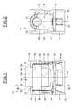
Figure 1 is a cross-section of a cam follower roller device according to a first example of the invention, -
Figure 2 is a section on II-II ofFigure 1 , -
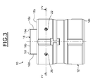
Figure 3 is a front view of the device ofFigure 1 , -
Figure 4 is a section on IV-IV ofFigure 3 , and -
Figure 5 is a section of a cam follower roller device according to a second example of the invention. - As shown on
Figures 1 and 2 , a camfollower roller device 10 comprises an outer tappet housing orbody 12 extending along anaxis 12a, a shaft orpin 14 extending along anaxis 14a perpendicular to theaxis 12a, aroller 16 mounted on the pin and movable in rotation relative to said pin, and a stroke transmission part or insert 18 mounted in said tappet body. Theinsert 18 supports thepin 14 while thetappet body 12 supports said insert. As will be described later, lubricant supply through-holes Figure 3 and4 ) are provided on thetappet body 12 in order to lubricate both theroller 16 and thepin 14. - In the disclosed embodiment, the
roller 16 is directly mounted on thepin 14. Alternatively, a rolling bearing or a plain bearing may be radially interposed. Theroller 16 comprises an axialcylindrical bore 16a mounted on an outer surface of thepin 14, and an axial cylindricalouter surface 16b radially opposed to the said bore. Theouter surface 16b of the roller forms a contact surface intended to bear against the associated cam of the internal combustion engine. - The
roller 16 also comprises two opposite radialfrontal end faces bore 16a and theouter surface 16b. Theroller 16 further comprises a first annular chamfer oredge 16e delimited between theouter surface 16b and theend face 16c, and a second annular chamfer oredge 16f delimited between said outer surface and theother end face 16d. Eachedge outer surface 16b and to the associatedend face - The
tappet body 12 is made in one part. In the disclosed example, thebody 12 has a tubular form. Thetappet body 12 comprises a cylindrical axial outer surface and a cylindrical axial inner bore or surface. Said inner surface delimits acavity 28 inside which are located theinsert 18 and thepin 14. Theroller 16 axially protrudes outwards with respect to anupper face 12b of thetappet body 12. Thetappet body 12 also comprises alower face 12c which delimits axially together with theupper face 12b said body. - The
insert 18 is made in one part. Theinsert 18 may preferably be made of metal, by example steel, or be made of plastic material. Theinsert 18 is distinct from thetappet body 12. In the disclosed example, theinsert 18 is entirely housed inside thecavity 28 delimited by thetappet body 12. - The
insert 18 comprises a base part orcentral core 30 and two side parts orlateral tabs tabs upper face 12b of the tappet body. Theinsert 18 has in cross-section a U-shape. Theroller 16 is disposed between thetabs concave recess pin 14. Both recesses 36, 38 extend through thetabs axis 14a and have the same diameter.Recesses pin 14. Each end of saidpin 14 is supported by one of the twotabs pin 14 is supported by theinsert 18. - The
tappet body 12 further comprises means 40, 42 for axially blocking thepin 14 and theroller 16 relative to said body. The axial blocking means 40, 42 block the translation ofpin 14 in a direction from thelower face 12c of the tappet towards theupper face 12b. The axial blocking means 40, 42 are integrally formed with thetappet body 12. In the illustrated example, these means 40, 42 are provided on the inner surface of the tappet body at theupper face 12b. The axial blocking means 40, 42 delimit receiving housings each facing one of the receivinghousings pin 14. Alternatively, it could be possible to provide a spacer comprising cylindrical through-holes made into the thickness of the lateral tabs and facing one another, the ends of thepin 14 being fixed in said through-holes. In the illustrated example, thetappet body 12 is made from synthetic material, such as polyamide for example. Thetappet body 12 is advantageously formed by moulding. Alternatively, thetappet body 12 may be made of metal, for example in an economic way by cutting, stamping and folding. - The
device 10 further comprises anannular retaining washer 44 housed inside thecavity 28 delimited by thetappet body 12 and mounted into axial contact with theinsert 18. Thewasher 44 enables to retain the unit formed by theinsert 18, thepin 14 and theroller 16 into thetappet body 12. Thewasher 44 axially abuts against theinsert 18 axially on the side opposite to theroller 14 and thepin 16. Thewasher 44 axially abuts against thecore 30 of the insert. In the disclosed example, thewasher 44 is a flat washer. Alternatively, an elastic washer, for instance a wavy washer, may be provided in order to exert a permanent axial preload on theinsert 18. Thewasher 44 may be open in the circumferential direction. - A plurality of
protrusions 46 are formed on the inner surface of thetappet body 12 and extends radially inwards to axially block thewasher 44 into said body. Theprotrusions 46 are integrally formed with thetappet body 12. Theprotrusions 46 are regularly spaced apart in the circumferential direction. Thewasher 44 is in axial contact against theinsert 18 on one side and in axial contact with theprotrusions 46 of the tappet body on the other side. Alternatively, an annular protrusion may be provided on the inner surface of thetappet body 12. - In this example, the
insert 18 is supported by thetappet body 12 with the aid of thewasher 44. Alternatively, theinsert 18 may be supported directly by thetappet body 12, without interposition of a washer, for example by forming radial protrusions on the inner surface of the tappet body which cooperate with the insert. - As previously mentioned, lubricant supply through-
holes 20 to 26 are formed on thetappet body 12 as shown onFigures 3 and4 . Each through-hole 20 to 26 is formed into the thickness of thetappet body 12. Each through-hole 20 to 26 extends from the outer surface of thetappet body 12 to the inner surface of said body. The through-holes open into said inner surface. The through-holes 20 to 26 are spaced apart from theupper face 12b of the tappet body. In the disclosed example, each through-hole has a cylindrical shape. For example, the diameter of the through-holes 20 to 26 may be from 0.5 mm to 3 mm. Alternatively, the through-holes may have any other different profile, for example a rectangular or a square one. In this example, the through-holes 20 to 26 are identical. - As shown more clearly on
Figure 4 , the through-holes tappet body 12 to locally face thefirst edge 16e of the roller. The through-holes holes axis 14a of the roller. Each through-hole axis edge 16e of the roller. The axis of each through-hole intersects theedge 16e. Each through-hole outer surface 16b of the roller and the outer surface of thepin 14. A part of each through-hole outer surface 16b of the roller and the other part of said hole is axially offset outwards relative to theend face 16c with respect to theaxis 14a. - Similarly, the through-
holes second edge 16f of the roller. The through-holes holes axis 14a of the roller. The through-holes holes roller 16. Each through-hole axis edge 16f of the roller. The axis of each through-hole intersects theedge 16f. Each through-hole outer surface 16b of the roller and the outer surface of thepin 14. A part of each through-hole outer surface 16b of the roller and the other part of said hole is axially offset outwards relative to theend face 16d with respect to theaxis 14a. - For lubricating the
device 10, a flow of lubricant, such as oil, is introduced into each of the lubricant supply through-holes 20 to 26 of the tappet body. For the sake of clarity ofFigure 4 , only the flow F coming from the through-hole 20 is illustrated. - The flow F is directed towards the
edge 16e of the roller, impacts said edge and is divided into two separate flows F1 and F2. The flow F1 is directed towards the outer surface of thepin 14 while the flow F2 is directed towards theouter surface 16b of the roller. The flow F1 is caused to flow towards thepin 14 between theend face 16c of the roller and a part of the inner surface of the tappet body facing said end face. The flow F2 flows along theouter surface 16b of the roller. - The supply through-
hole 20 enables the lubrication of theouter surface 16b of the roller as well as the rolling contact area betweenbore 16a of said roller and thepin 14. In the illustrated example, since theaxis 20a of the through-hole 20 intersects theedge 16e of the roller, the supplied flow F of lubricant is split into equal individual flows F1 and F2 at this edge. Alternatively, according to the orientation of the supply through-hole 20 with respect to theedge 16e of the roller, the flow F may be split into two individual flows F1 and F2 in a predetermined ratio. - In this example, the through-
holes 20 to 26 of the tappet body extends radially with regard to theaxis 14a of the roller. Alternatively, it is possible to foresee another orientation of the through-holes. For example, in the second example illustrated onFigure 5 , in which identical parts are given identical references, the through-holes 20 to 26 of the tappet body extends axially with regard to theaxis 14a of the roller. - In this example, each through-
hole edge 16e and theend face 16c of the roller. A part of each through-hole end face 16c and the other part of said hole is radially offset outwards relative to theouter surface 16b of said roller with respect to theaxis 14a. Similarly to the first example, theaxis hole edge 16e of the roller. Each through-hole edge 16f and theend face 16d of the roller. A part of each through-hole end face 16d and the other part of said hole is radially offset outwards relative to theouter surface 16b of said roller with respect to theaxis 14a. Theaxis hole edge 16f of the roller. In this example, the through-holes - In another variant, it could be possible to foresee another orientation of the through-
holes 20 to 26 of the tappet body taken within an angular range of about 90 degrees delimited by the first and second positions as shown in the illustrated examples. - In the described examples, the through-
holes 20 to 26 of the tappet body extend into a radial plane of the device perpendicular to theaxis 12 of said body and passing through theroller 16. Alternatively, the lubricant supply through-holes may be tilted with respect to the radial plane in order to each delimit with said plane a clockwise or counterclockwise angle. - The invention has been illustrated on the basis of a cam follower roller device comprising an insert secured to the tappet body and supporting the pin. Alternatively, it could be possible to directly mount the pin on the tappet body, for example by providing through-holes into the thickness of said body. In this case, the device is deprived of such insert.
Claims (15)
- Cam follower roller device comprising a tappet body (12), a pin (14) mounted into said tappet body, and a roller (16) mounted on said pin and provided with an outer surface (16b) and with end faces (16c, 16d) axially delimiting said outer surface, characterized in that at least one lubricant supply through-hole (20) is formed into the thickness of the tappet body (12) and locally faces an edge (16e) of the roller delimited between the outer surface (16b) and one of the end faces (16c, 16d).
- Device according to claim 1, wherein an axis (20a) of said lubricant supply through-hole (20) is oriented towards said edge of the roller.
- Device according to claim 1 or 2, wherein said lubricant supply through-hole (20) partly faces the outer surface (16b) of the roller and/or said end face of said roller.
- Device according to any of the preceding claims, wherein said lubricant supply through-hole (20) is spaced apart from an upper face (12b) of the tappet body.
- Device according to any of the preceding claims, wherein said lubricant supply through-hole (20) extends into a radial plane of said device perpendicular to an axis (12) of the tappet body.
- Device according to any of the preceding claims 1 to 4, wherein said lubricant supply through-hole (20) is tilted with respect to a radial plane of said device perpendicular to an axis (12) of the tappet body.
- Device according to any of the preceding claims, wherein the tappet body (12) comprises at least first and second lubricant supply through-holes (20, 24) formed into the thickness of the tappet body (12), said first lubricant supply through-hole locally facing said edge (16e) of the roller delimited between the outer surface (16b) and said end face (16c), said second lubricant supply through-hole locally facing another edge (16f) of the roller delimited between said outer surface and the other end face (16d).
- Device according to claim 7, wherein the tappet body (12) comprises at least a pair of first lubricant supply through-holes (20, 22) and a pair of second lubricant supply through-holes (24, 26).
- Device according to claim 8, wherein said through-holes of each pair face one another.
- Device according to claim 8 or 9, wherein the two pairs of first and second lubricant supply through-holes are symmetrical relative to an axial plane of said device passing through the centre of the roller (16).
- Device according to any of the preceding claims, further comprising an insert (18) mounted in the tappet body (12), the pin (14) being mounted at least on said insert.
- Device according to any of the preceding claims, wherein the insert (18) comprises a central core (30) and at least two side tabs (32, 34) each comprising a receiving housing (36, 38) for an end of the pin (14).
- Device according to any of the preceding claims 1 to 10, wherein the pin (14) is mounted on the tappet body (12).
- Method for lubricating a cam follower roller device comprising a tappet body, a pin mounted in said tappet body and a roller mounted on said pin and provided with an outer surface and with end faces axially delimiting said outer surface, characterized in that at least one flow of lubricant emerging from a lubricant supply through-hole formed into the thickness of the tappet body is directed towards an edge of the roller delimited between the outer surface and one of the end faces of the roller, and impacts said edge in order that a part of said flow is caused to flow towards the pin and that the other part of said flow is caused to flow towards the outer surface of the roller.
- method according to claim 13, wherein at least one additional flow of lubricant emerging from another lubricant supply through-hole formed into the thickness of the tappet body is directed towards another edge of the roller delimited between the outer surface and the other end face of the roller, and impacts said another edge in order that a part of said additional flow is caused to flow towards the pin and that the other part of said additional flow is caused to flow towards the outer surface of the roller.
Priority Applications (3)
| Application Number | Priority Date | Filing Date | Title |
|---|---|---|---|
| EP15306857.2A EP3173592B1 (en) | 2015-11-24 | 2015-11-24 | Cam follower roller device with lubricant supply holes and lubricating method |
| US15/346,073 US10718240B2 (en) | 2015-11-24 | 2016-11-08 | Cam follower roller device with lubricant supply holes and lubricating method |
| CN201611037522.4A CN106988827A (en) | 2015-11-24 | 2016-11-23 | Cam driven roller arrangement and lubricating method with lubricant supply hole |
Applications Claiming Priority (1)
| Application Number | Priority Date | Filing Date | Title |
|---|---|---|---|
| EP15306857.2A EP3173592B1 (en) | 2015-11-24 | 2015-11-24 | Cam follower roller device with lubricant supply holes and lubricating method |
Publications (2)
| Publication Number | Publication Date |
|---|---|
| EP3173592A1 true EP3173592A1 (en) | 2017-05-31 |
| EP3173592B1 EP3173592B1 (en) | 2021-01-06 |
Family
ID=54703917
Family Applications (1)
| Application Number | Title | Priority Date | Filing Date |
|---|---|---|---|
| EP15306857.2A Active EP3173592B1 (en) | 2015-11-24 | 2015-11-24 | Cam follower roller device with lubricant supply holes and lubricating method |
Country Status (3)
| Country | Link |
|---|---|
| US (1) | US10718240B2 (en) |
| EP (1) | EP3173592B1 (en) |
| CN (1) | CN106988827A (en) |
Cited By (1)
| Publication number | Priority date | Publication date | Assignee | Title |
|---|---|---|---|---|
| WO2020088800A1 (en) * | 2018-11-03 | 2020-05-07 | Eaton Intelligent Power Limited | Pump actuator and method of assembling same |
Families Citing this family (5)
| Publication number | Priority date | Publication date | Assignee | Title |
|---|---|---|---|---|
| EP3173591B1 (en) * | 2015-11-24 | 2018-07-11 | Aktiebolaget SKF | Cam follower roller device with spacer |
| WO2017181002A2 (en) * | 2016-04-15 | 2017-10-19 | Koyo Bearings North America Llc | Tappet with inner cup received on pallet |
| FR3079583B1 (en) * | 2018-04-03 | 2020-03-06 | Aktiebolaget Skf | PULLEY DEVICE FOR TENSIONER OR ROLLER |
| US10794347B1 (en) * | 2019-08-10 | 2020-10-06 | Woodward, Inc. | Roller reaction force lubrication system |
| US11149593B2 (en) * | 2019-10-03 | 2021-10-19 | Koyo Bearings North America Llc | Tappet assembly with formed anti-rotation alignment device |
Citations (7)
| Publication number | Priority date | Publication date | Assignee | Title |
|---|---|---|---|---|
| US20010004886A1 (en) * | 1998-12-01 | 2001-06-28 | Paul Brothers | Valve lifter apparatus |
| DE102006031032A1 (en) * | 2006-07-05 | 2008-01-10 | Schaeffler Kg | Tappet for fuel high pressure pump of internal combustion engine, has cross-hole for supplying lubricant to shell surface and bearing surface, and tappet skirt with outer annular groove that connects cross hole with lubricant supply channel |
| DE102010030498A1 (en) * | 2010-06-24 | 2011-12-29 | Robert Bosch Gmbh | Pump, in particular high-pressure fuel pump |
| DE102012223413A1 (en) * | 2012-12-17 | 2014-06-18 | Robert Bosch Gmbh | Roller tappet for a pump, in particular high-pressure fuel pump, and pump with roller tappet |
| US8851038B1 (en) * | 2008-12-09 | 2014-10-07 | Ed Iskenderian Racing Cams | Roller valve lifter |
| EP2853738A1 (en) | 2013-09-27 | 2015-04-01 | Aktiebolaget SKF | Mechanical system, injection pump and valve actuator comprising such a mechanical system and manufacturing method |
| EP2937566A1 (en) * | 2014-04-22 | 2015-10-28 | Aktiebolaget SKF | Cam follower roller device, notably for a fuel injection pump |
Family Cites Families (15)
| Publication number | Priority date | Publication date | Assignee | Title |
|---|---|---|---|---|
| US1802330A (en) * | 1929-05-24 | 1931-04-28 | Aeromarine Plane & Motor Compa | Valve mechanism |
| US4231267A (en) * | 1978-11-01 | 1980-11-04 | General Motors Corporation | Roller hydraulic valve lifter |
| DE19729793A1 (en) * | 1997-07-11 | 1999-01-14 | Bosch Gmbh Robert | Piston pump for high-pressure fuel supply |
| JP4446105B2 (en) * | 1999-06-25 | 2010-04-07 | ヤマハ発動機株式会社 | 4-cycle engine |
| DE19958314A1 (en) * | 1999-12-03 | 2001-06-07 | Mahle Ventiltrieb Gmbh | Roller plunger |
| JP5303468B2 (en) | 2006-12-05 | 2013-10-02 | シャエフラー カーゲー | Mechanical tappets, especially for internal combustion engine fuel pumps |
| US7793583B2 (en) * | 2006-12-06 | 2010-09-14 | Schaeffler Kg | Mechanical tappet in particular for a fuel pump of an internal combustion engine |
| US8397689B2 (en) * | 2010-05-17 | 2013-03-19 | GM Global Technology Operations LLC | Fuel pump tappet/roller follower lubrication |
| EP3002426B1 (en) * | 2014-09-30 | 2017-11-08 | Aktiebolaget SKF | Mechanical system forming a cam follower or a rocker arm |
| EP3002425B1 (en) * | 2014-09-30 | 2018-07-04 | Aktiebolaget SKF | Mechanical system forming a cam follower or a rocker arm |
| US9441505B1 (en) * | 2014-11-17 | 2016-09-13 | Topline Automotive Engineering, Inc. | Roller lifter with improved oil injection port and supply groove |
| EP3026255B1 (en) * | 2014-11-27 | 2020-11-18 | Aktiebolaget SKF | Mechanical system forming a cam follower or a rocker arm, injection pump or valve actuator comprising such a mechanical system and method for manufacturing such a mechanical system |
| EP3026231B1 (en) * | 2014-11-27 | 2020-08-12 | Aktiebolaget SKF | Mechanical system forming a cam follower or a rocker arm, injection pump or valve actuator comprising such a mechanical system and method for manufacturing such a mechanical system |
| EP3026232B1 (en) * | 2014-11-27 | 2020-01-08 | Aktiebolaget SKF | Mechanical system forming a cam follower or a rocker arm, injection pump or valve actuator comprising such a mechanical system and method for manufacturing such a mechanical system |
| EP3073066B1 (en) * | 2015-03-27 | 2017-10-18 | Aktiebolaget SKF | Cam follower, injection pump and valve actuator comprising such a cam follower, and manufacturing method |
-
2015
- 2015-11-24 EP EP15306857.2A patent/EP3173592B1/en active Active
-
2016
- 2016-11-08 US US15/346,073 patent/US10718240B2/en active Active
- 2016-11-23 CN CN201611037522.4A patent/CN106988827A/en active Pending
Patent Citations (7)
| Publication number | Priority date | Publication date | Assignee | Title |
|---|---|---|---|---|
| US20010004886A1 (en) * | 1998-12-01 | 2001-06-28 | Paul Brothers | Valve lifter apparatus |
| DE102006031032A1 (en) * | 2006-07-05 | 2008-01-10 | Schaeffler Kg | Tappet for fuel high pressure pump of internal combustion engine, has cross-hole for supplying lubricant to shell surface and bearing surface, and tappet skirt with outer annular groove that connects cross hole with lubricant supply channel |
| US8851038B1 (en) * | 2008-12-09 | 2014-10-07 | Ed Iskenderian Racing Cams | Roller valve lifter |
| DE102010030498A1 (en) * | 2010-06-24 | 2011-12-29 | Robert Bosch Gmbh | Pump, in particular high-pressure fuel pump |
| DE102012223413A1 (en) * | 2012-12-17 | 2014-06-18 | Robert Bosch Gmbh | Roller tappet for a pump, in particular high-pressure fuel pump, and pump with roller tappet |
| EP2853738A1 (en) | 2013-09-27 | 2015-04-01 | Aktiebolaget SKF | Mechanical system, injection pump and valve actuator comprising such a mechanical system and manufacturing method |
| EP2937566A1 (en) * | 2014-04-22 | 2015-10-28 | Aktiebolaget SKF | Cam follower roller device, notably for a fuel injection pump |
Cited By (1)
| Publication number | Priority date | Publication date | Assignee | Title |
|---|---|---|---|---|
| WO2020088800A1 (en) * | 2018-11-03 | 2020-05-07 | Eaton Intelligent Power Limited | Pump actuator and method of assembling same |
Also Published As
| Publication number | Publication date |
|---|---|
| US10718240B2 (en) | 2020-07-21 |
| CN106988827A (en) | 2017-07-28 |
| EP3173592B1 (en) | 2021-01-06 |
| US20170145877A1 (en) | 2017-05-25 |
Similar Documents
| Publication | Publication Date | Title |
|---|---|---|
| EP3173592B1 (en) | Cam follower roller device with lubricant supply holes and lubricating method | |
| EP2853738B1 (en) | Mechanical system, injection pump and valve actuator comprising such a mechanical system and manufacturing method | |
| EP3073066B1 (en) | Cam follower, injection pump and valve actuator comprising such a cam follower, and manufacturing method | |
| EP2853698B1 (en) | Cam follower, injection pump and valve actuator comprising such a cam follower and manufacturing method | |
| EP3002426B1 (en) | Mechanical system forming a cam follower or a rocker arm | |
| EP2853696B1 (en) | Mechanical system, injection pump and valve actuator comprising such a mechanical system and manufacturing method | |
| EP2960446A1 (en) | Mechanical system forming a cam follower or a rocker arm | |
| US9752670B2 (en) | Mechanical system forming a cam follower or a rocker arm | |
| EP3173612A1 (en) | Cam follower roller device with retaining plug | |
| EP3085945A1 (en) | Cam follower, injection pump and valve actuator comprising such a cam follower, and manufacturing method | |
| EP2944800A1 (en) | Method for manufacturing a roller, adapted to equip a mechanical system forming a cam follower or a rocker arm | |
| US9745934B2 (en) | Mechanical system forming a cam follower or a rocker arm | |
| EP2937566B1 (en) | Cam follower roller device, notably for a fuel injection pump | |
| EP3121436B1 (en) | Cam follower roller device and associated manufacturing method | |
| US10385956B2 (en) | Mechanical system forming a cam follower or a rocker arm | |
| EP2853697B1 (en) | Mechanical system, injection pump and valve actuator comprising such a mechanical system and manufacturing method | |
| EP3173591B1 (en) | Cam follower roller device with spacer | |
| EP3165722A1 (en) | Cam follower roller device with insert | |
| EP3173590B1 (en) | Cam follower roller device with washer | |
| EP3176393B1 (en) | Cam follower roller device with spacer and improved wear resistance |
Legal Events
| Date | Code | Title | Description |
|---|---|---|---|
| PUAI | Public reference made under article 153(3) epc to a published international application that has entered the european phase |
Free format text: ORIGINAL CODE: 0009012 |
|
| STAA | Information on the status of an ep patent application or granted ep patent |
Free format text: STATUS: THE APPLICATION HAS BEEN PUBLISHED |
|
| AK | Designated contracting states |
Kind code of ref document: A1 Designated state(s): AL AT BE BG CH CY CZ DE DK EE ES FI FR GB GR HR HU IE IS IT LI LT LU LV MC MK MT NL NO PL PT RO RS SE SI SK SM TR |
|
| AX | Request for extension of the european patent |
Extension state: BA ME |
|
| STAA | Information on the status of an ep patent application or granted ep patent |
Free format text: STATUS: REQUEST FOR EXAMINATION WAS MADE |
|
| 17P | Request for examination filed |
Effective date: 20171024 |
|
| STAA | Information on the status of an ep patent application or granted ep patent |
Free format text: STATUS: EXAMINATION IS IN PROGRESS |
|
| 17Q | First examination report despatched |
Effective date: 20190408 |
|
| GRAP | Despatch of communication of intention to grant a patent |
Free format text: ORIGINAL CODE: EPIDOSNIGR1 |
|
| STAA | Information on the status of an ep patent application or granted ep patent |
Free format text: STATUS: GRANT OF PATENT IS INTENDED |
|
| INTG | Intention to grant announced |
Effective date: 20200616 |
|
| GRAS | Grant fee paid |
Free format text: ORIGINAL CODE: EPIDOSNIGR3 |
|
| GRAA | (expected) grant |
Free format text: ORIGINAL CODE: 0009210 |
|
| STAA | Information on the status of an ep patent application or granted ep patent |
Free format text: STATUS: THE PATENT HAS BEEN GRANTED |
|
| AK | Designated contracting states |
Kind code of ref document: B1 Designated state(s): AL AT BE BG CH CY CZ DE DK EE ES FI FR GB GR HR HU IE IS IT LI LT LU LV MC MK MT NL NO PL PT RO RS SE SI SK SM TR |
|
| REG | Reference to a national code |
Ref country code: GB Ref legal event code: FG4D |
|
| REG | Reference to a national code |
Ref country code: AT Ref legal event code: REF Ref document number: 1352601 Country of ref document: AT Kind code of ref document: T Effective date: 20210115 Ref country code: CH Ref legal event code: EP |
|
| REG | Reference to a national code |
Ref country code: DE Ref legal event code: R096 Ref document number: 602015064375 Country of ref document: DE |
|
| REG | Reference to a national code |
Ref country code: IE Ref legal event code: FG4D |
|
| REG | Reference to a national code |
Ref country code: NL Ref legal event code: MP Effective date: 20210106 |
|
| REG | Reference to a national code |
Ref country code: AT Ref legal event code: MK05 Ref document number: 1352601 Country of ref document: AT Kind code of ref document: T Effective date: 20210106 |
|
| REG | Reference to a national code |
Ref country code: LT Ref legal event code: MG9D |
|
| PG25 | Lapsed in a contracting state [announced via postgrant information from national office to epo] |
Ref country code: NO Free format text: LAPSE BECAUSE OF FAILURE TO SUBMIT A TRANSLATION OF THE DESCRIPTION OR TO PAY THE FEE WITHIN THE PRESCRIBED TIME-LIMIT Effective date: 20210406 Ref country code: NL Free format text: LAPSE BECAUSE OF FAILURE TO SUBMIT A TRANSLATION OF THE DESCRIPTION OR TO PAY THE FEE WITHIN THE PRESCRIBED TIME-LIMIT Effective date: 20210106 Ref country code: BG Free format text: LAPSE BECAUSE OF FAILURE TO SUBMIT A TRANSLATION OF THE DESCRIPTION OR TO PAY THE FEE WITHIN THE PRESCRIBED TIME-LIMIT Effective date: 20210406 Ref country code: FI Free format text: LAPSE BECAUSE OF FAILURE TO SUBMIT A TRANSLATION OF THE DESCRIPTION OR TO PAY THE FEE WITHIN THE PRESCRIBED TIME-LIMIT Effective date: 20210106 Ref country code: HR Free format text: LAPSE BECAUSE OF FAILURE TO SUBMIT A TRANSLATION OF THE DESCRIPTION OR TO PAY THE FEE WITHIN THE PRESCRIBED TIME-LIMIT Effective date: 20210106 Ref country code: GR Free format text: LAPSE BECAUSE OF FAILURE TO SUBMIT A TRANSLATION OF THE DESCRIPTION OR TO PAY THE FEE WITHIN THE PRESCRIBED TIME-LIMIT Effective date: 20210407 Ref country code: PT Free format text: LAPSE BECAUSE OF FAILURE TO SUBMIT A TRANSLATION OF THE DESCRIPTION OR TO PAY THE FEE WITHIN THE PRESCRIBED TIME-LIMIT Effective date: 20210506 Ref country code: LT Free format text: LAPSE BECAUSE OF FAILURE TO SUBMIT A TRANSLATION OF THE DESCRIPTION OR TO PAY THE FEE WITHIN THE PRESCRIBED TIME-LIMIT Effective date: 20210106 |
|
| PG25 | Lapsed in a contracting state [announced via postgrant information from national office to epo] |
Ref country code: SE Free format text: LAPSE BECAUSE OF FAILURE TO SUBMIT A TRANSLATION OF THE DESCRIPTION OR TO PAY THE FEE WITHIN THE PRESCRIBED TIME-LIMIT Effective date: 20210106 Ref country code: RS Free format text: LAPSE BECAUSE OF FAILURE TO SUBMIT A TRANSLATION OF THE DESCRIPTION OR TO PAY THE FEE WITHIN THE PRESCRIBED TIME-LIMIT Effective date: 20210106 Ref country code: PL Free format text: LAPSE BECAUSE OF FAILURE TO SUBMIT A TRANSLATION OF THE DESCRIPTION OR TO PAY THE FEE WITHIN THE PRESCRIBED TIME-LIMIT Effective date: 20210106 Ref country code: LV Free format text: LAPSE BECAUSE OF FAILURE TO SUBMIT A TRANSLATION OF THE DESCRIPTION OR TO PAY THE FEE WITHIN THE PRESCRIBED TIME-LIMIT Effective date: 20210106 Ref country code: AT Free format text: LAPSE BECAUSE OF FAILURE TO SUBMIT A TRANSLATION OF THE DESCRIPTION OR TO PAY THE FEE WITHIN THE PRESCRIBED TIME-LIMIT Effective date: 20210106 |
|
| PG25 | Lapsed in a contracting state [announced via postgrant information from national office to epo] |
Ref country code: IS Free format text: LAPSE BECAUSE OF FAILURE TO SUBMIT A TRANSLATION OF THE DESCRIPTION OR TO PAY THE FEE WITHIN THE PRESCRIBED TIME-LIMIT Effective date: 20210506 |
|
| REG | Reference to a national code |
Ref country code: DE Ref legal event code: R097 Ref document number: 602015064375 Country of ref document: DE |
|
| PG25 | Lapsed in a contracting state [announced via postgrant information from national office to epo] |
Ref country code: CZ Free format text: LAPSE BECAUSE OF FAILURE TO SUBMIT A TRANSLATION OF THE DESCRIPTION OR TO PAY THE FEE WITHIN THE PRESCRIBED TIME-LIMIT Effective date: 20210106 Ref country code: EE Free format text: LAPSE BECAUSE OF FAILURE TO SUBMIT A TRANSLATION OF THE DESCRIPTION OR TO PAY THE FEE WITHIN THE PRESCRIBED TIME-LIMIT Effective date: 20210106 Ref country code: SM Free format text: LAPSE BECAUSE OF FAILURE TO SUBMIT A TRANSLATION OF THE DESCRIPTION OR TO PAY THE FEE WITHIN THE PRESCRIBED TIME-LIMIT Effective date: 20210106 |
|
| PLBE | No opposition filed within time limit |
Free format text: ORIGINAL CODE: 0009261 |
|
| STAA | Information on the status of an ep patent application or granted ep patent |
Free format text: STATUS: NO OPPOSITION FILED WITHIN TIME LIMIT |
|
| PG25 | Lapsed in a contracting state [announced via postgrant information from national office to epo] |
Ref country code: DK Free format text: LAPSE BECAUSE OF FAILURE TO SUBMIT A TRANSLATION OF THE DESCRIPTION OR TO PAY THE FEE WITHIN THE PRESCRIBED TIME-LIMIT Effective date: 20210106 Ref country code: SK Free format text: LAPSE BECAUSE OF FAILURE TO SUBMIT A TRANSLATION OF THE DESCRIPTION OR TO PAY THE FEE WITHIN THE PRESCRIBED TIME-LIMIT Effective date: 20210106 Ref country code: RO Free format text: LAPSE BECAUSE OF FAILURE TO SUBMIT A TRANSLATION OF THE DESCRIPTION OR TO PAY THE FEE WITHIN THE PRESCRIBED TIME-LIMIT Effective date: 20210106 |
|
| 26N | No opposition filed |
Effective date: 20211007 |
|
| PG25 | Lapsed in a contracting state [announced via postgrant information from national office to epo] |
Ref country code: AL Free format text: LAPSE BECAUSE OF FAILURE TO SUBMIT A TRANSLATION OF THE DESCRIPTION OR TO PAY THE FEE WITHIN THE PRESCRIBED TIME-LIMIT Effective date: 20210106 Ref country code: ES Free format text: LAPSE BECAUSE OF FAILURE TO SUBMIT A TRANSLATION OF THE DESCRIPTION OR TO PAY THE FEE WITHIN THE PRESCRIBED TIME-LIMIT Effective date: 20210106 |
|
| PG25 | Lapsed in a contracting state [announced via postgrant information from national office to epo] |
Ref country code: SI Free format text: LAPSE BECAUSE OF FAILURE TO SUBMIT A TRANSLATION OF THE DESCRIPTION OR TO PAY THE FEE WITHIN THE PRESCRIBED TIME-LIMIT Effective date: 20210106 |
|
| PG25 | Lapsed in a contracting state [announced via postgrant information from national office to epo] |
Ref country code: IT Free format text: LAPSE BECAUSE OF FAILURE TO SUBMIT A TRANSLATION OF THE DESCRIPTION OR TO PAY THE FEE WITHIN THE PRESCRIBED TIME-LIMIT Effective date: 20210106 |
|
| PG25 | Lapsed in a contracting state [announced via postgrant information from national office to epo] |
Ref country code: IS Free format text: LAPSE BECAUSE OF FAILURE TO SUBMIT A TRANSLATION OF THE DESCRIPTION OR TO PAY THE FEE WITHIN THE PRESCRIBED TIME-LIMIT Effective date: 20210506 |
|
| PG25 | Lapsed in a contracting state [announced via postgrant information from national office to epo] |
Ref country code: MC Free format text: LAPSE BECAUSE OF FAILURE TO SUBMIT A TRANSLATION OF THE DESCRIPTION OR TO PAY THE FEE WITHIN THE PRESCRIBED TIME-LIMIT Effective date: 20210106 |
|
| REG | Reference to a national code |
Ref country code: CH Ref legal event code: PL |
|
| GBPC | Gb: european patent ceased through non-payment of renewal fee |
Effective date: 20211124 |
|
| PG25 | Lapsed in a contracting state [announced via postgrant information from national office to epo] |
Ref country code: LU Free format text: LAPSE BECAUSE OF NON-PAYMENT OF DUE FEES Effective date: 20211124 Ref country code: BE Free format text: LAPSE BECAUSE OF NON-PAYMENT OF DUE FEES Effective date: 20211130 |
|
| REG | Reference to a national code |
Ref country code: BE Ref legal event code: MM Effective date: 20211130 |
|
| PG25 | Lapsed in a contracting state [announced via postgrant information from national office to epo] |
Ref country code: IE Free format text: LAPSE BECAUSE OF NON-PAYMENT OF DUE FEES Effective date: 20211124 Ref country code: GB Free format text: LAPSE BECAUSE OF NON-PAYMENT OF DUE FEES Effective date: 20211124 |
|
| PG25 | Lapsed in a contracting state [announced via postgrant information from national office to epo] |
Ref country code: HU Free format text: LAPSE BECAUSE OF FAILURE TO SUBMIT A TRANSLATION OF THE DESCRIPTION OR TO PAY THE FEE WITHIN THE PRESCRIBED TIME-LIMIT; INVALID AB INITIO Effective date: 20151124 |
|
| P01 | Opt-out of the competence of the unified patent court (upc) registered |
Effective date: 20230513 |
|
| PG25 | Lapsed in a contracting state [announced via postgrant information from national office to epo] |
Ref country code: CY Free format text: LAPSE BECAUSE OF FAILURE TO SUBMIT A TRANSLATION OF THE DESCRIPTION OR TO PAY THE FEE WITHIN THE PRESCRIBED TIME-LIMIT Effective date: 20210106 |
|
| PG25 | Lapsed in a contracting state [announced via postgrant information from national office to epo] |
Ref country code: LI Free format text: LAPSE BECAUSE OF NON-PAYMENT OF DUE FEES Effective date: 20220701 Ref country code: CH Free format text: LAPSE BECAUSE OF NON-PAYMENT OF DUE FEES Effective date: 20220701 |
|
| PG25 | Lapsed in a contracting state [announced via postgrant information from national office to epo] |
Ref country code: MK Free format text: LAPSE BECAUSE OF FAILURE TO SUBMIT A TRANSLATION OF THE DESCRIPTION OR TO PAY THE FEE WITHIN THE PRESCRIBED TIME-LIMIT Effective date: 20210106 |
|
| PG25 | Lapsed in a contracting state [announced via postgrant information from national office to epo] |
Ref country code: MT Free format text: LAPSE BECAUSE OF FAILURE TO SUBMIT A TRANSLATION OF THE DESCRIPTION OR TO PAY THE FEE WITHIN THE PRESCRIBED TIME-LIMIT Effective date: 20210106 |
|
| PGFP | Annual fee paid to national office [announced via postgrant information from national office to epo] |
Ref country code: FR Payment date: 20241126 Year of fee payment: 10 |
|
| PG25 | Lapsed in a contracting state [announced via postgrant information from national office to epo] |
Ref country code: TR Free format text: LAPSE BECAUSE OF FAILURE TO SUBMIT A TRANSLATION OF THE DESCRIPTION OR TO PAY THE FEE WITHIN THE PRESCRIBED TIME-LIMIT Effective date: 20210106 |
|
| PGFP | Annual fee paid to national office [announced via postgrant information from national office to epo] |
Ref country code: DE Payment date: 20251126 Year of fee payment: 11 |
|
| REG | Reference to a national code |
Ref country code: DE Ref legal event code: R082 Ref document number: 602015064375 Country of ref document: DE Representative=s name: SCHONECKE, MITJA, DIPL.-PHYS. DR. RER. NAT., DE Ref country code: DE Ref legal event code: R082 Ref document number: 602015064375 Country of ref document: DE Representative=s name: SCHONECKE, MITJA, DR., DE |
|
| REG | Reference to a national code |
Ref country code: DE Ref legal event code: R082 Ref document number: 602015064375 Country of ref document: DE Representative=s name: SCHONECKE, MITJA, DR., DE |