EP3173563A1 - Hinge and damping device - Google Patents
Hinge and damping device Download PDFInfo
- Publication number
- EP3173563A1 EP3173563A1 EP16192344.6A EP16192344A EP3173563A1 EP 3173563 A1 EP3173563 A1 EP 3173563A1 EP 16192344 A EP16192344 A EP 16192344A EP 3173563 A1 EP3173563 A1 EP 3173563A1
- Authority
- EP
- European Patent Office
- Prior art keywords
- abutting part
- movable member
- damper
- movable
- component
- Prior art date
- Legal status (The legal status is an assumption and is not a legal conclusion. Google has not performed a legal analysis and makes no representation as to the accuracy of the status listed.)
- Granted
Links
Images








Classifications
-
- E—FIXED CONSTRUCTIONS
- E05—LOCKS; KEYS; WINDOW OR DOOR FITTINGS; SAFES
- E05F—DEVICES FOR MOVING WINGS INTO OPEN OR CLOSED POSITION; CHECKS FOR WINGS; WING FITTINGS NOT OTHERWISE PROVIDED FOR, CONCERNED WITH THE FUNCTIONING OF THE WING
- E05F5/00—Braking devices, e.g. checks; Stops; Buffers
- E05F5/06—Buffers or stops limiting opening of swinging wings, e.g. floor or wall stops
- E05F5/10—Buffers or stops limiting opening of swinging wings, e.g. floor or wall stops with piston brakes
-
- E—FIXED CONSTRUCTIONS
- E05—LOCKS; KEYS; WINDOW OR DOOR FITTINGS; SAFES
- E05F—DEVICES FOR MOVING WINGS INTO OPEN OR CLOSED POSITION; CHECKS FOR WINGS; WING FITTINGS NOT OTHERWISE PROVIDED FOR, CONCERNED WITH THE FUNCTIONING OF THE WING
- E05F5/00—Braking devices, e.g. checks; Stops; Buffers
- E05F5/006—Braking devices, e.g. checks; Stops; Buffers for hinges having a cup-shaped fixing part, e.g. for attachment to cabinets or furniture
-
- E—FIXED CONSTRUCTIONS
- E05—LOCKS; KEYS; WINDOW OR DOOR FITTINGS; SAFES
- E05Y—INDEXING SCHEME ASSOCIATED WITH SUBCLASSES E05D AND E05F, RELATING TO CONSTRUCTION ELEMENTS, ELECTRIC CONTROL, POWER SUPPLY, POWER SIGNAL OR TRANSMISSION, USER INTERFACES, MOUNTING OR COUPLING, DETAILS, ACCESSORIES, AUXILIARY OPERATIONS NOT OTHERWISE PROVIDED FOR, APPLICATION THEREOF
- E05Y2201/00—Constructional elements; Accessories therefor
- E05Y2201/20—Brakes; Disengaging means; Holders; Stops; Valves; Accessories therefor
- E05Y2201/21—Brakes
-
- E—FIXED CONSTRUCTIONS
- E05—LOCKS; KEYS; WINDOW OR DOOR FITTINGS; SAFES
- E05Y—INDEXING SCHEME ASSOCIATED WITH SUBCLASSES E05D AND E05F, RELATING TO CONSTRUCTION ELEMENTS, ELECTRIC CONTROL, POWER SUPPLY, POWER SIGNAL OR TRANSMISSION, USER INTERFACES, MOUNTING OR COUPLING, DETAILS, ACCESSORIES, AUXILIARY OPERATIONS NOT OTHERWISE PROVIDED FOR, APPLICATION THEREOF
- E05Y2201/00—Constructional elements; Accessories therefor
- E05Y2201/20—Brakes; Disengaging means; Holders; Stops; Valves; Accessories therefor
- E05Y2201/214—Disengaging means
-
- E—FIXED CONSTRUCTIONS
- E05—LOCKS; KEYS; WINDOW OR DOOR FITTINGS; SAFES
- E05Y—INDEXING SCHEME ASSOCIATED WITH SUBCLASSES E05D AND E05F, RELATING TO CONSTRUCTION ELEMENTS, ELECTRIC CONTROL, POWER SUPPLY, POWER SIGNAL OR TRANSMISSION, USER INTERFACES, MOUNTING OR COUPLING, DETAILS, ACCESSORIES, AUXILIARY OPERATIONS NOT OTHERWISE PROVIDED FOR, APPLICATION THEREOF
- E05Y2201/00—Constructional elements; Accessories therefor
- E05Y2201/20—Brakes; Disengaging means; Holders; Stops; Valves; Accessories therefor
- E05Y2201/252—Type of friction
- E05Y2201/254—Fluid or viscous friction
- E05Y2201/256—Fluid or viscous friction with pistons or vanes
-
- E—FIXED CONSTRUCTIONS
- E05—LOCKS; KEYS; WINDOW OR DOOR FITTINGS; SAFES
- E05Y—INDEXING SCHEME ASSOCIATED WITH SUBCLASSES E05D AND E05F, RELATING TO CONSTRUCTION ELEMENTS, ELECTRIC CONTROL, POWER SUPPLY, POWER SIGNAL OR TRANSMISSION, USER INTERFACES, MOUNTING OR COUPLING, DETAILS, ACCESSORIES, AUXILIARY OPERATIONS NOT OTHERWISE PROVIDED FOR, APPLICATION THEREOF
- E05Y2201/00—Constructional elements; Accessories therefor
- E05Y2201/20—Brakes; Disengaging means; Holders; Stops; Valves; Accessories therefor
- E05Y2201/262—Type of motion, e.g. braking
- E05Y2201/264—Type of motion, e.g. braking linear
-
- E—FIXED CONSTRUCTIONS
- E05—LOCKS; KEYS; WINDOW OR DOOR FITTINGS; SAFES
- E05Y—INDEXING SCHEME ASSOCIATED WITH SUBCLASSES E05D AND E05F, RELATING TO CONSTRUCTION ELEMENTS, ELECTRIC CONTROL, POWER SUPPLY, POWER SIGNAL OR TRANSMISSION, USER INTERFACES, MOUNTING OR COUPLING, DETAILS, ACCESSORIES, AUXILIARY OPERATIONS NOT OTHERWISE PROVIDED FOR, APPLICATION THEREOF
- E05Y2600/00—Mounting or coupling arrangements for elements provided for in this subclass
- E05Y2600/10—Adjustable
- E05Y2600/12—Adjustable by manual operation
-
- E—FIXED CONSTRUCTIONS
- E05—LOCKS; KEYS; WINDOW OR DOOR FITTINGS; SAFES
- E05Y—INDEXING SCHEME ASSOCIATED WITH SUBCLASSES E05D AND E05F, RELATING TO CONSTRUCTION ELEMENTS, ELECTRIC CONTROL, POWER SUPPLY, POWER SIGNAL OR TRANSMISSION, USER INTERFACES, MOUNTING OR COUPLING, DETAILS, ACCESSORIES, AUXILIARY OPERATIONS NOT OTHERWISE PROVIDED FOR, APPLICATION THEREOF
- E05Y2900/00—Application of doors, windows, wings or fittings thereof
- E05Y2900/20—Application of doors, windows, wings or fittings thereof for furniture, e.g. cabinets
Definitions
- the present invention is related to a damping device and a hinge.
- a damping device is applicable to a first object and a second object movable relative to each other, in order to provide damping effect when the second object is moved to switch from an open state to a close state relative to the first object, so as to mitigate movement of the second object being closed relative to the first object.
- US patent numbers US 7, 971, 691 B2 discloses a damper for movable furniture parts.
- the damper comprises a housing, a cylinder arranged in the housing, a piston with a piston rod movable relative to the cylinder, a stop for abutting against the piston rod and a transmission arranged on the housing and configured to adjust the stop to move along a longitudinal direction of the piston rod.
- an actuation element (9) is configured to be driven by a tool, such as a screwdriver to spirally adjust the stop (7, 14) to move longitudinally, in order to adjust the piston rod.
- a tool such as a screwdriver
- the case provides an adjustable damper.
- dampers with different damping-stroke adjusting methods can be provided to bring more options to the market.
- the present invention aims at providing a damping device and a hinge.
- the claimed damping device comprises a damper and a blocking member.
- the damper comprises a first movable member and a second movable member longitudinally movable relative to each other.
- the first movable member has a first abutting part and a second abutting part.
- the first abutting part and the second abutting part are located at different longitudinal positions on the first movable member.
- the blocking member is movable relative to the damper and configured to abut against one of the first abutting part and the second abutting part of the first movable member.
- the damping device is applicable to two components movable relative to each other.
- One of the two components has a contact part.
- the damping device comprises a housing, a damper and a blocking member.
- the damper is arranged in the housing.
- the damper comprises a first movable member and a second movable member longitudinally movable relative to each other. A length is defined by the first movable member and the second movable member.
- the first movable member has a first abutting part and a second abutting part.
- the first abutting part and the second abutting part are located at different longitudinal positions on the first movable member.
- the second movable member is configured to abut against the contact part.
- the blocking member is movable relative to the damper and configured to abut against one of the first abutting part and the second abutting part of the first movable member in order to adjust the distance.
- the claimed hinge comprises a first component, a second component, an elastic member, a linkage member and a damping device.
- the first component comprises a contact part.
- the second component is pivoted to the first component.
- the elastic member is configured to provide an elastic force when the second component is opened or closed relative to the first component.
- the linkage member is configured to move when the second component is rotated relative to the first component.
- the damping device is mounted to one of the first component and the second component.
- the damping device comprises a damper and a blocking member.
- the damper comprises a first movable member and a second movable member longitudinally movable relative to each other.
- the first movable member has a first abutting part and a second abutting part.
- the first abutting part and the second abutting part are located at different longitudinal positions on the first movable member.
- the second movable member faces toward the contact part of the first component.
- the blocking member is movable relative to the damper and configured to abut against one of the first abutting part and the second abutting part of the first movable member. Wherein, when the second component is moved to switch from an open state to a close state relative to the first component with the blocking member abutting against one of the first abutting part and the second abutting part of the first movable member, the linkage member is moved toward the first movable member of the damper.
- FIG. 1 and FIG. 2 are diagrams showing a hinge 20 applicable to two objects movable relative to each other according to an embodiment of the present invention.
- the two objects can be a first furniture part22 and a second furniture part 24 for example.
- the hinge 20 comprises a first component 26 mounted to the first furniture part 22, and a second component 28 mounted to the second furniture part 24.
- the first component 26 can be a hinge arm.
- the second component 28 can be a hinge cup. Wherein, the second component 28 is pivoted to the first component 26, such that the second furniture part 24 can be opened or closed relative to the first furniture part 22.
- the hinge 20 further comprises at least one elastic member 29 configured to provide an elastic force when the second component 28 is opened or closed relative to the first component 26.
- the first component 26 of the hinge 20 comprises a contact part 30, such as a supporting shaft.
- the hinge 20 further comprises a linkage member 32 and a damping device 34.
- the linkage member 30 is configured to abut against the damping device 34 in response to the second component 28 moving toward a close position relative to the first component 26, in order to mitigate a force for closing.
- the damping device 34 can be mounted to one of the first component 26 and the second component 28. In the present embodiment, the damping device 34 is mounted to the first component 26 for example.
- the damping device 34 comprises a damper 36 and a blocking member 38.
- the damper 36 is configured to provide damping effect.
- the damper 36 comprises a first movable member 40 and a second movable member 42 longitudinally movable relative to each other.
- the first movable member 40 can be a cylinder
- the second movable member 42 can be a piston rod constantly driven by a force to extend out of the cylinder.
- operation of the cylinder and the piston rod is well known to those skilled in the art, therefore, no further illustration is provided.
- the hinge 20 further comprises a sleeve member 44 detachably mounted to the contact part 30 of the first component 26.
- the sleeve member 44 has a fastening part 46 configured to be engaged with the contact part 30.
- the second movable member 42 of the damper 36 faces toward the contact part 30 of the first component 26.
- the second movable member 42 abuts against the contact part 30 of the first component 26 through the sleeve member 44.
- the first movable member 40 of the damper 36 has a first abutting part 48 and a second abutting part 50.
- the first movable member 40 further comprises a third abutting part 52.
- the first abutting part 48, the second abutting part 50 and the third abutting part 52 are located at different longitudinal positions on the first movable member 40.
- the hinge 20 in the present embodiment further comprises a housing 54 arranged on the first component 26.
- the housing 54 comprises a passage 56 and an auxiliary base 58 arranged adjacent to the passage 56.
- the passage 56 is configured to accommodate the damper 36, such as accommodating the first movable member 40 of the damper 36.
- the auxiliary base 58 has a pair of mounting holes 60.
- the blocking member 38 can be arranged on the auxiliary base 58.
- the blocking member 38 comprises a main body 62 and a flexible part 64 connected to the main body 62.
- the main body 62 has an opening 66.
- the damping device further comprises an adjusting member 68 arranged on the blocking member 38.
- the adjusting member 68 comprises a first fastening member 70 and a second fastening member 72 respectively having a first hook part 74 and a second hook part 76.
- the first fastening member 70 and the second fastening member 72 penetrates through the opening 66 of the blocking member 38 via predetermined holes 27a, 27b on the first component 26 of the hinge 20 and the mounting holes 60 of the auxiliary base 58.
- the first fastening member 70 and the second fastening member 72 are engaged with each other by the first hook part 74 and the second hook part 76.
- the first fastening member 70 and the second fastening member 72 are respectively located at two sides of the blocking member 38 and extended out of the first component 26 of the hinge 20 in order to facilitate operation for pushing the blocking member 38 to move.
- the auxiliary base 58 of the housing 54 has a plurality of engaging features, such as a first engaging feature 75a, a second engaging feature 75b and a third engaging feature 75c.
- the blocking member 38 has a positioning feature 77.
- the engaging features 75a, 75b and 75c can be grooves, and the positioning feature 77 can be a protrusion.
- the blocking member 38 is movable relative to the damper 36.
- the adjusting member 68 such as pushing the second fastening member 72 of the adjusting member 68, to adjust the blocking member 38 to transversely move relative to the damper 36 to a first position L1
- the positioning feature 77 of the blocking member 38 is correspondingly engaged with the first engaging feature 75a of the auxiliary base 58 of the housing 54.
- the positioning feature 77 of the blocking member 38 is correspondingly engaged with the second engaging feature 75b of the auxiliary base 58 of the housing 54.
- the linkage member 32 starts to push the first movable member 40 of the damper 36 when the second component 28 is moved relative to the first component 26 to be at a first angle A1.
- the second movable member 42 of the damper 36 abuts against the sleeve member 44.
- the first movable member 40 of the damper 36 is moved relative to the second movable member 42 according to a damping stroke corresponding to the first length D1, in order to provide a first damping effect to mitigate movement of the second component 28 being closed relative to the first component 26.
- the first damping effect is provided when the second furniture part 24 is closed relative to the first furniture part 22.
- the flexible part 64 of the blocking member 38 abuts against the second abutting part 50 of the first movable member 40 of the damper 36, such that a second length D2 is defined by the first movable member 40 and the second movable member 42 of the damper 36.
- the second length D2 is smaller than the first length D1.
- the linkage member 32 starts to push (or contact) the first movable member 40 of the damper 36 when the second component 28 is nearly at the close state, such that a second damping effect provided by the damper 36 is almost zero.
- the linkage member 32 does not push (or contact) the first movable member 40 of the damper 36 even the linkage member 32 is moved toward the first movable member 40 of the damper 36.
- the second damping effect provided by the damper 36 is zero during the process of the second component 28 being moved to switch from the open state to the close state relative to the first component 26.
- the blocking member 38 when the blocking member 38 is adjusted to move to the third position L3, the flexible part 64 of the blocking member 38 abuts against the third abutting part 52 of the first movable member 40 of the damper 36, such that a third length D3 is defined by the first movable member 40 and the second movable member 42 of the damper 36.
- the third length D3 is between the first length D1 and the second length D2. That is to say, the first length D1 is greater than the third length D3, and the third length D3 is greater than the second length D2.
- the relationship between the first to third lengths D1-D3 can be represented by an equation: D1>D3>D2.
- the linkage member 32 is moved toward the first movable member 40 of the damper 36 along with the second component 28 rotating relative to the first component 26.
- the linkage member 32 starts to push the first movable member 40 of the damper 36 when the second component 28 is moved relative to the first component 26 to be at a second angle A2.
- the second movable member 42 of the damper 36 abuts against the sleeve member 44.
- the first movable member 40 of the damper 36 is moved relative to the second movable member 42 according to a damping stroke corresponding to the third length D3, in order to provide a third damping effect to mitigate movement of the second component 28 being closed relative to the first component 26.
- the third damping effect is provided when the second furniture part 24 is closed relative to the first furniture part 22.
- the blocking member 38 in an operation mode, is operatively moved from the first position L1 to the third position L3 relative to the damper 36.
- the first movable member 40 of the damper 36 can be operatively moved relative to the second movable member 42 along a longitudinal direction D, such that the flexible part 64, which previously abutted against the first abutting part 48, is adjusted to abut against the third abutting part 52.
- the flexible part 64 of the blocking member 38 is pushed by a lateral side of the third abutting part 52 for accumulating an elastic force, and the flexible part 64 releases the elastic force to abut against the third abutting part 52 of the first movable member 40 of the damper 36 once the first movable member 40 is moved to a predetermined position along the longitudinal direction D.
- the blocking member 38 is operatively moved from the third position L3 to the second position L2 relative to the damper 36.
- the first movable member 40 of the damper 36 can be operatively moved relative to the second movable member 42 along the longitudinal direction D, such that the flexible part 64, which previously abutted against the third abutting part 52, is adjusted to abut against the second abutting part 50.
- the flexible part 64 of the blocking member 38 is pushed by a lateral side of the second abutting part 50 for accumulating an elastic force, and the flexible part 64 releases the elastic force to abut against the second abutting part 50 of the first movable member 40 of the damper 36 once the first movable member 40 is moved to another predetermined position along the longitudinal direction D.
Landscapes
- Hinges (AREA)
- Vibration Dampers (AREA)
- Vibration Prevention Devices (AREA)
Abstract
Description
- The present invention is related to a damping device and a hinge.
- Generally, a damping device is applicable to a first object and a second object movable relative to each other, in order to provide damping effect when the second object is moved to switch from an open state to a close state relative to the first object, so as to mitigate movement of the second object being closed relative to the first object. For example, US patent numbers
US 7, 971, 691 B2 discloses a damper for movable furniture parts. The damper comprises a housing, a cylinder arranged in the housing, a piston with a piston rod movable relative to the cylinder, a stop for abutting against the piston rod and a transmission arranged on the housing and configured to adjust the stop to move along a longitudinal direction of the piston rod. Wherein, according to an embodiment of the case shown inFIG. 1a , an actuation element (9) is configured to be driven by a tool, such as a screwdriver to spirally adjust the stop (7, 14) to move longitudinally, in order to adjust the piston rod. The case provides an adjustable damper. However, for different market requirements, dampers with different damping-stroke adjusting methods can be provided to bring more options to the market. - This in mind, the present invention aims at providing a damping device and a hinge.
- This is achieved by a damping device according to claims 1 and 7, and a hinge according to claim 13. The dependent claims pertain to corresponding further developments and improvements.
- As will be seen more clearly from the detailed description following below, the claimed damping device comprises a damper and a blocking member. The damper comprises a first movable member and a second movable member longitudinally movable relative to each other. The first movable member has a first abutting part and a second abutting part. The first abutting part and the second abutting part are located at different longitudinal positions on the first movable member. The blocking member is movable relative to the damper and configured to abut against one of the first abutting part and the second abutting part of the first movable member.
- As will be seen more clearly from the detailed description following below, the claimed damping device is applicable to two components movable relative to each other. One of the two components has a contact part. The damping device comprises a housing, a damper and a blocking member. The damper is arranged in the housing. The damper comprises a first movable member and a second movable member longitudinally movable relative to each other. A length is defined by the first movable member and the second movable member. The first movable member has a first abutting part and a second abutting part. The first abutting part and the second abutting part are located at different longitudinal positions on the first movable member. The second movable member is configured to abut against the contact part. The blocking member is movable relative to the damper and configured to abut against one of the first abutting part and the second abutting part of the first movable member in order to adjust the distance.
- As will be seen more clearly from the detailed description following below, the claimed hinge comprises a first component, a second component, an elastic member, a linkage member and a damping device. The first component comprises a contact part. The second component is pivoted to the first component. The elastic member is configured to provide an elastic force when the second component is opened or closed relative to the first component. The linkage member is configured to move when the second component is rotated relative to the first component. The damping device is mounted to one of the first component and the second component. The damping device comprises a damper and a blocking member. The damper comprises a first movable member and a second movable member longitudinally movable relative to each other. The first movable member has a first abutting part and a second abutting part. The first abutting part and the second abutting part are located at different longitudinal positions on the first movable member. The second movable member faces toward the contact part of the first component. The blocking member is movable relative to the damper and configured to abut against one of the first abutting part and the second abutting part of the first movable member. Wherein, when the second component is moved to switch from an open state to a close state relative to the first component with the blocking member abutting against one of the first abutting part and the second abutting part of the first movable member, the linkage member is moved toward the first movable member of the damper.
- In the following, the invention is further illustrated by way of example, taking reference to the accompanying drawings thereof:
-
FIG. 1 is a diagram showing a hinge applicable to two objects being in an open state according to an embodiment of the present invention; -
FIG. 2 is a diagram showing the two objects inFIG. 1 being in a close state; -
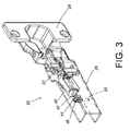
FIG. 3 is a diagram showing the hinge according to an embodiment of the present invention; -
FIG. 4 is a top view of the hinge according to an embodiment of the present invention; -
FIG. 5 is an exploded view of the hinge with a damping device according to an embodiment of the present invention; -
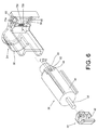
FIG. 6 is an exploded view of the damping device according to an embodiment of the present invention; -
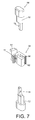
FIG. 7 is an exploded view of an adjusting member and a blocking member according to an embodiment of the present invention; -
FIG. 8 is a diagram showing the blocking member being adjusted to move to a first position relative to a damper; -
FIG. 9 is a diagram showing a housing of the damping device inFIG. 8 having a first engaging feature configured to engage with the blocking member when the blocking member is located at the first position; -
FIG. 10 is a diagram showing the blocking member being adjusted to move to a second position relative to the damper; -
FIG. 11 is a diagram showing the housing of the damping device inFIG. 10 having a second engaging feature configured to engage with the blocking member when the blocking member is located at the second position; -
FIG. 12 is a diagram showing the blocking member being adjusted to move to a third position relative to the damper; -
FIG. 13 is a diagram showing the housing of the damping device inFIG. 12 having a third engaging feature configured to engage with the blocking member when the blocking member is located at the third position; -
FIG. 14 is a diagram showing the hinge being in an open state according to an embodiment of the present invention, wherein the blocking member abuts against a first abutting part of the damper; -
FIG. 14A is an enlarged view of anarea 14A inFIG. 14 ; -
FIG. 15 is a diagram showing a linkage member pushing the damper in a process of the hinge inFIG. 14 being moved to switch from the open state to a close state when a second component of the hinge is at a first angle; -
FIG. 16 is a diagram showing the hinge inFIG. 15 being in the close state; -
FIG. 17 is a diagram showing the hinge being in an open state according to an embodiment of the present invention, wherein the blocking member abuts against a second abutting part of the damper; -
FIG. 17A is an enlarged view of anarea 17A inFIG. 17 ; -
FIG. 18 is a diagram showing the hinge inFIG. 17 being in the close state; -
FIG. 19 is a diagram showing the hinge being in the open state according to an embodiment of the present invention, wherein the blocking member abuts against a third abutting part of the damper; -
FIG. 19A is an enlarged view of anarea 19A inFIG. 19 ; -
FIG. 20 is a diagram showing the linkage member pushing the damper in a process of the hinge inFIG. 19 being moved to switch from the open state to the close state when the second component of the hinge is at a second angle; -
FIG. 21 is a diagram showing the hinge inFIG. 20 being in the close state; -
FIG. 22 is a diagram showing the blocking member being located at the first position relative to the damper according to an embodiment of the present invention; -
FIG. 23 is a diagram showing the blocking member inFIG. 22 being located at the first position relative to the damper in another angle; -
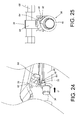
FIG. 24 is a diagram showing the blocking member inFIG. 22 being moved relative to the damper with a first movable member of the damper being moved along a direction; -
FIG. 25 is a diagram showing the blocking member inFIG. 24 being moved relative to the damper in another angle; -
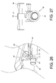
FIG. 26 is a diagram showing the blocking member being located at the third position relative to the damper according to an embodiment of the present invention; -
FIG. 27 is a diagram showing the blocking member inFIG. 26 being located at the third position relative to the damper in another angle; -
FIG. 28 is a diagram showing the blocking member inFIG. 26 being moved relative to the damper with the first movable member of the damper being moved along the direction; -
FIG. 29 is a diagram showing the blocking member inFIG. 28 being moved relative to the damper in another angle; -
FIG. 30 is a diagram showing the blocking member being located at a second position relative to the damper according to an embodiment of the present invention; and -
FIG. 31 is a diagram showing the blocking member inFIG. 30 being located at the second position relative to the damper in another angle. -
FIG. 1 andFIG. 2 are diagrams showing ahinge 20 applicable to two objects movable relative to each other according to an embodiment of the present invention. In the present embodiment, the two objects can be a first furniture part22 and asecond furniture part 24 for example. Thehinge 20 comprises afirst component 26 mounted to thefirst furniture part 22, and asecond component 28 mounted to thesecond furniture part 24. Thefirst component 26 can be a hinge arm. Thesecond component 28 can be a hinge cup. Wherein, thesecond component 28 is pivoted to thefirst component 26, such that thesecond furniture part 24 can be opened or closed relative to thefirst furniture part 22. Thehinge 20 further comprises at least oneelastic member 29 configured to provide an elastic force when thesecond component 28 is opened or closed relative to thefirst component 26. - As shown in
FIG. 3 andFIG. 4 , thefirst component 26 of thehinge 20 comprises acontact part 30, such as a supporting shaft. In particular, thehinge 20 further comprises alinkage member 32 and a dampingdevice 34. Thelinkage member 30 is configured to abut against the dampingdevice 34 in response to thesecond component 28 moving toward a close position relative to thefirst component 26, in order to mitigate a force for closing. The dampingdevice 34 can be mounted to one of thefirst component 26 and thesecond component 28. In the present embodiment, the dampingdevice 34 is mounted to thefirst component 26 for example. - As shown in
FIG. 5 , the dampingdevice 34 comprises adamper 36 and a blockingmember 38. Thedamper 36 is configured to provide damping effect. Thedamper 36 comprises a firstmovable member 40 and a secondmovable member 42 longitudinally movable relative to each other. In the present embodiment, the firstmovable member 40 can be a cylinder, and the secondmovable member 42 can be a piston rod constantly driven by a force to extend out of the cylinder. Wherein, operation of the cylinder and the piston rod is well known to those skilled in the art, therefore, no further illustration is provided. In the present embodiment, thehinge 20 further comprises asleeve member 44 detachably mounted to thecontact part 30 of thefirst component 26. For example, thesleeve member 44 has afastening part 46 configured to be engaged with thecontact part 30. The secondmovable member 42 of thedamper 36 faces toward thecontact part 30 of thefirst component 26. In the present embodiment, the secondmovable member 42 abuts against thecontact part 30 of thefirst component 26 through thesleeve member 44. - As shown in
FIG. 5 andFIG. 6 , the firstmovable member 40 of thedamper 36 has a first abuttingpart 48 and a secondabutting part 50. Preferably, the firstmovable member 40 further comprises a thirdabutting part 52. The firstabutting part 48, the second abuttingpart 50 and the third abuttingpart 52 are located at different longitudinal positions on the firstmovable member 40. For example, the first abuttingpart 48 is located at a first longitudinal position P1 on the firstmovable member 40; the second abuttingpart 50 is located at a second longitudinal position P2 on the firstmovable member 40; the third abuttingpart 52 is located at a third longitudinal position P3 on the firstmovable member 40. Preferably, thehinge 20 in the present embodiment further comprises ahousing 54 arranged on thefirst component 26. Thehousing 54 comprises apassage 56 and anauxiliary base 58 arranged adjacent to thepassage 56. Thepassage 56 is configured to accommodate thedamper 36, such as accommodating the firstmovable member 40 of thedamper 36. Theauxiliary base 58 has a pair of mountingholes 60. - As shown in
FIG. 5 ,FIG. 6 andFIG. 7 , the blockingmember 38 can be arranged on theauxiliary base 58. The blockingmember 38 comprises amain body 62 and aflexible part 64 connected to themain body 62. Themain body 62 has anopening 66. Preferably, the damping device further comprises an adjustingmember 68 arranged on the blockingmember 38. The adjustingmember 68 comprises afirst fastening member 70 and asecond fastening member 72 respectively having afirst hook part 74 and asecond hook part 76. Thefirst fastening member 70 and thesecond fastening member 72 penetrates through theopening 66 of the blockingmember 38 viapredetermined holes 27a, 27b on thefirst component 26 of thehinge 20 and the mountingholes 60 of theauxiliary base 58. Thefirst fastening member 70 and thesecond fastening member 72 are engaged with each other by thefirst hook part 74 and thesecond hook part 76. Thefirst fastening member 70 and thesecond fastening member 72 are respectively located at two sides of the blockingmember 38 and extended out of thefirst component 26 of thehinge 20 in order to facilitate operation for pushing the blockingmember 38 to move. Preferably, theauxiliary base 58 of thehousing 54 has a plurality of engaging features, such as a firstengaging feature 75a, a secondengaging feature 75b and a thirdengaging feature 75c. On the other hand, the blockingmember 38 has apositioning feature 77. In the present embodiment, the engagingfeatures positioning feature 77 can be a protrusion. - As shown in
FIG. 8 and FIG. 9 , the blockingmember 38 is movable relative to thedamper 36. In particular, when a user operates the adjustingmember 68, such as pushing thesecond fastening member 72 of the adjustingmember 68, to adjust the blockingmember 38 to transversely move relative to thedamper 36 to a first position L1, thepositioning feature 77 of the blockingmember 38 is correspondingly engaged with the firstengaging feature 75a of theauxiliary base 58 of thehousing 54. - As shown in
FIG. 10 and FIG. 11 , when the user operates the adjustingmember 68, such as pushing thefirst fastening member 70 of the adjustingmember 68, to adjust the blockingmember 38 to transversely move relative to thedamper 36 to a second position L2, thepositioning feature 77 of the blockingmember 38 is correspondingly engaged with the secondengaging feature 75b of theauxiliary base 58 of thehousing 54. - As shown in
FIG. 12 and FIG. 13 , when the user operates the adjustingmember 68 to adjust the blockingmember 38 to transversely move relative to thedamper 36 to a third position L3, thepositioning feature 77 of the blockingmember 38 is correspondingly engaged with the thirdengaging feature 75c of theauxiliary base 58 of thehousing 54. - As shown in
FIG. 14, FIG. 14A, FIG. 15 and FIG. 16 , when the blockingmember 38 is adjusted to move to the first position L1, theflexible part 64 of the blockingmember 38 abuts against the first abuttingpart 48 of the firstmovable member 40 of thedamper 36, such that a first length D1 is defined by the firstmovable member 40 and the secondmovable member 42 of thedamper 36. In such state, during a process of thesecond component 28 being moved to switch from an open state to a close state relative to thefirst component 26, thelinkage member 32 is moved toward the firstmovable member 40 of thedamper 36 along with thesecond component 28 rotating relative to thefirst component 26. Wherein, thelinkage member 32 starts to push the firstmovable member 40 of thedamper 36 when thesecond component 28 is moved relative to thefirst component 26 to be at a first angle A1. On the other hand, the secondmovable member 42 of thedamper 36 abuts against thesleeve member 44. As such, when thelinkage member 32 continues to push the firstmovable member 40 of thedamper 36, the firstmovable member 40 of thedamper 36 is moved relative to the secondmovable member 42 according to a damping stroke corresponding to the first length D1, in order to provide a first damping effect to mitigate movement of thesecond component 28 being closed relative to thefirst component 26. In other words, the first damping effect is provided when thesecond furniture part 24 is closed relative to thefirst furniture part 22. - As shown in
FIG. 17, FIG. 17A and FIG. 18 , when the blockingmember 38 is adjusted to move to the second position L2, theflexible part 64 of the blockingmember 38 abuts against the second abuttingpart 50 of the firstmovable member 40 of thedamper 36, such that a second length D2 is defined by the firstmovable member 40 and the secondmovable member 42 of thedamper 36. Wherein, the second length D2 is smaller than the first length D1. In such state, during the process of thesecond component 28 being moved to switch from the open state to the close state relative to thefirst component 26, thelinkage member 32 starts to push (or contact) the firstmovable member 40 of thedamper 36 when thesecond component 28 is nearly at the close state, such that a second damping effect provided by thedamper 36 is almost zero. Or, in the state that the firstmovable member 40 and the secondmovable member 42 of thedamper 36 define the second length D2, during the process of thesecond component 28 being moved to switch from the open state to the close state relative to thefirst component 26, thelinkage member 32 does not push (or contact) the firstmovable member 40 of thedamper 36 even thelinkage member 32 is moved toward the firstmovable member 40 of thedamper 36. In other words, the second damping effect provided by thedamper 36 is zero during the process of thesecond component 28 being moved to switch from the open state to the close state relative to thefirst component 26. - As shown in
FIG. 19, FIG. 19A, FIG. 20 and FIG. 21 , when the blockingmember 38 is adjusted to move to the third position L3, theflexible part 64 of the blockingmember 38 abuts against the third abuttingpart 52 of the firstmovable member 40 of thedamper 36, such that a third length D3 is defined by the firstmovable member 40 and the secondmovable member 42 of thedamper 36. Wherein, the third length D3 is between the first length D1 and the second length D2. That is to say, the first length D1 is greater than the third length D3, and the third length D3 is greater than the second length D2. The relationship between the first to third lengths D1-D3 can be represented by an equation: D1>D3>D2. In such state, during the process of thesecond component 28 being moved to switch from the open state to the close state relative to thefirst component 26, thelinkage member 32 is moved toward the firstmovable member 40 of thedamper 36 along with thesecond component 28 rotating relative to thefirst component 26. Wherein, thelinkage member 32 starts to push the firstmovable member 40 of thedamper 36 when thesecond component 28 is moved relative to thefirst component 26 to be at a second angle A2. On the other hand, the secondmovable member 42 of thedamper 36 abuts against thesleeve member 44. As such, when thelinkage member 32 continues to push thefirst member 40 of thedamper 36, the firstmovable member 40 of thedamper 36 is moved relative to the secondmovable member 42 according to a damping stroke corresponding to the third length D3, in order to provide a third damping effect to mitigate movement of thesecond component 28 being closed relative to thefirst component 26. In other words, the third damping effect is provided when thesecond furniture part 24 is closed relative to thefirst furniture part 22. - As shown in
FIG. 22 and FIG. 23 , when the blockingmember 38 is located at the first position L1 relative to thedamper 36, theflexible part 64 of the blockingmember 38 abuts against the first abuttingpart 48 of the firstmovable member 40 of thedamper 36. - As shown in
FIG. 24, FIG. 25 ,FIG. 26 and FIG. 27 , in an operation mode, the blockingmember 38 is operatively moved from the first position L1 to the third position L3 relative to thedamper 36. For example, when the user operates the adjustingmember 68 to move the blockingmember 38 transversely (laterally) relative to thedamper 36 from the first position L1 to the third position L3, the firstmovable member 40 of thedamper 36 can be operatively moved relative to the secondmovable member 42 along a longitudinal direction D, such that theflexible part 64, which previously abutted against the first abuttingpart 48, is adjusted to abut against the third abuttingpart 52. In such process, theflexible part 64 of the blockingmember 38 is pushed by a lateral side of the third abuttingpart 52 for accumulating an elastic force, and theflexible part 64 releases the elastic force to abut against the third abuttingpart 52 of the firstmovable member 40 of thedamper 36 once the firstmovable member 40 is moved to a predetermined position along the longitudinal direction D. - As shown in
FIG. 28, FIG. 29 ,FIG. 30 and FIG. 31 , the blockingmember 38 is operatively moved from the third position L3 to the second position L2 relative to thedamper 36. For example, when the user operates the adjustingmember 68 to move the blockingmember 38 transversely (laterally) relative to thedamper 36 from the third position L3 to the second position L2, the firstmovable member 40 of thedamper 36 can be operatively moved relative to the secondmovable member 42 along the longitudinal direction D, such that theflexible part 64, which previously abutted against the third abuttingpart 52, is adjusted to abut against the second abuttingpart 50. In such process, theflexible part 64 of the blockingmember 38 is pushed by a lateral side of the second abuttingpart 50 for accumulating an elastic force, and theflexible part 64 releases the elastic force to abut against the second abuttingpart 50 of the firstmovable member 40 of thedamper 36 once the firstmovable member 40 is moved to another predetermined position along the longitudinal direction D.
Claims (15)
- A damping device (34), characterized by:a damper (36) comprising a first movable member (40) and a second movable member (42) longitudinally movable relative to each other, the first movable member (40) having a first abutting part (48) and a second abutting part (50), the first abutting part (48) and the second abutting part (50) being located at different longitudinal positions on the first movable member (40) ; anda blocking member (38) movable relative to the damper (36) and configured to abut against one of the first abutting part (48) and the second abutting part (50) of the first movable member (40).
- The damping device of claim 1, further characterized by an adjusting member (68) configured to adjust the blocking member (38) to transversely move relative to the damper (36).
- The damping device of claim 2, further characterized by a housing (54) having a passage (56) configured to accommodate the damper (36), wherein the adjusting member (68) is arranged adjacent to the housing (54).
- The damping device of claim 3, characterized in that the housing (54) further comprises an auxiliary base (58) arranged adjacent to the passage (56), the auxiliary base (58) has a plurality of engaging features (75a, 75b, 75c), the blocking member (38) is arranged on the auxiliary base (58), and the blocking member (38) has a positioning feature (77) configured to be engaged with one of the plurality of engaging features (75a, 75b, 75c).
- The damping device of any of claims 2-4, characterized in that the blocking member (38) has an opening (66), and the adjusting member (68) comprises a first fastening member (70) and a second fastening member (72) penetrating through the opening (66) and fastened to each other.
- The damping device of any of claims 1-5, characterized in that the first movable member (40) further has a third abutting part (52) located at a longitudinal position different from the longitudinal positions of the first abutting part (48) and the second abutting part (50) on the first movable member (40), the blocking member (38) comprises a main body (62) and a flexible part (64) connected to the main body (62), the flexible part (64) is configured to selectively abut against one of the first abutting part (48), the second abutting part (50) and the third abutting part (52).
- A damping device (34), applicable to two components (26, 28) movable relative to each other, one of the two components having a contact part (30), the damping device (34) comprising:a housing (54);characterized by:a damper (36) arranged in the housing (54), the damper (36) comprising a first movable member (40) and a second movable member (42) longitudinally movable relative to each other, a length being defined by the first movable member (40) and the second movable member (42), the first movable member (40) having a first abutting part (48) and a second abutting part (50), the first abutting part (48) and the second abutting part (50) being located at different longitudinal positions on the first movable member (40), the second movable member (42) configured to abut against the contact part (30); anda blocking member (38) movable relative to the damper (36) and configured to abut against one of the first abutting part (48) and the second abutting part (50) of the first movable member (40) in order to adjust the distance.
- The damping device of claim 7, further characterized by an adjusting member (68) configured to adjust the blocking member (38) to transversely move relative to the damper (36).
- The damping device of claim 8, characterized in that the housing (54) has a passage (56) configured to accommodate the damper (36), the adjusting member (68) is arranged adjacent to the housing (54).
- The damping device of claim 9, characterized in that the housing (54) further comprises an auxiliary base (58) arranged adjacent to the passage (56), the auxiliary base (58) has a plurality of engaging features (75a, 75b, 75c), the blocking member (38) is arranged on the auxiliary base (58), and the blocking member (38) has a positioning feature (77) configured to be engaged with one of the plurality of engaging features (75a, 75b, 75c).
- The damping device of any of claims 8-10, characterized in that the blocking member (38) has an opening (66), and the adjusting member (68) comprises a first fastening member (70) and a second fastening member (72) penetrating through the opening (66) and fastened to each other.
- The damping device of any of claims 7-11, characterized in that the first movable member (40) further has a third abutting part (52) located at a longitudinal position different from the longitudinal positions of the first abutting part (48) and the second abutting part (50) on the first movable member (40), the blocking member (38) comprises a main body (62) and a flexible part (64) connected to the main body (62), the flexible part (64) is configured to selectively abut against one of the first abutting part (48), the second abutting part (50) and the third abutting part (52) in order to adjust the distance.
- A hinge (20), comprising:a first component (26) comprising a contact part (30);a second component (28) pivoted to the first component (26);an elastic member (29) configured to provide an elastic force when the second component (28) is opened or closed relative to the first component (26);a linkage member (32) configured to move when the second component (28) is rotated relative to the first component (26); andcharacterized by:a damping device (34) mounted to one of the first component (26) and the second component (28), the damping device (34) comprising:a damper (36) comprising a first movable member (40) and a second movable member (42) longitudinally movable relative to each other, the first movable member (40) having a first abutting part (48) and a second abutting part (50), the first abutting part (48) and the second abutting part (50) being located at different longitudinal positions on the first movable member (40), the second movable member (42) facing toward the contact part (30) of the first component (26); anda blocking member (38) movable relative to the damper (36) and configured to abut against one of the first abutting part (48) and the second abutting part (50) of the first movable member (40);wherein when the second component (28) is moved to switch from an open state to a close state relative to the first component (26) with the blocking member (38) abutting against one of the first abutting part (48) and the second abutting part (50) of the first movable member (40), the linkage member (32) is moved toward the first movable member (40) of the damper (36).
- The hinge of claim 13, characterized in that the first movable member (40) further has a third abutting part (52) located at a longitudinal position different from the longitudinal positions of the first abutting part (48) and the second abutting part (50) on the first movable member (40), the damping device (34) further comprises an adjusting member (68) configured to adjust the blocking member (38) to transversely move relative to the damper (36) for abutting against one of the first abutting part (48), the second abutting part (50) and the third abutting part (52) of the first movable member (40).
- The hinge of claim 14, characterized in that the blocking member (38) comprises a main body (62) and a flexible part (64) connected to the main body (62), the main body (62) has an opening (66), the adjusting member (68) comprises a first fastening member (70) and a second fastening member (72) penetrating through the opening (66) and fastened to each other, the flexible part (64) of the blocking member (38) is configured to selectively abut against one of the first abutting part (48), the second abutting part (50) and the third abutting part (52).
Applications Claiming Priority (1)
| Application Number | Priority Date | Filing Date | Title |
|---|---|---|---|
| TW104139602A TWI555487B (en) | 2015-11-26 | 2015-11-26 | Hinge and damping device thereof |
Publications (2)
| Publication Number | Publication Date |
|---|---|
| EP3173563A1 true EP3173563A1 (en) | 2017-05-31 |
| EP3173563B1 EP3173563B1 (en) | 2019-04-03 |
Family
ID=57113121
Family Applications (1)
| Application Number | Title | Priority Date | Filing Date |
|---|---|---|---|
| EP16192344.6A Active EP3173563B1 (en) | 2015-11-26 | 2016-10-05 | Hinge and damping device |
Country Status (4)
| Country | Link |
|---|---|
| US (1) | US9840864B2 (en) |
| EP (1) | EP3173563B1 (en) |
| JP (1) | JP6326110B2 (en) |
| TW (1) | TWI555487B (en) |
Families Citing this family (10)
| Publication number | Priority date | Publication date | Assignee | Title |
|---|---|---|---|---|
| US10344517B2 (en) * | 2015-10-15 | 2019-07-09 | Hardware Resources, Inc. | Soft close device for compact hinges |
| US11401745B2 (en) * | 2017-02-13 | 2022-08-02 | Samet Kalip Ve Maden Esya San. Ve Tic A.S. | Furniture hinge having a blocking element for a linear damper |
| CN107013118B (en) * | 2017-05-25 | 2018-10-26 | 佛山市天斯五金有限公司 | Door hinge with pooling feature |
| DE102017114477A1 (en) * | 2017-06-29 | 2019-01-03 | Hettich-Oni Gmbh & Co. Kg | hinge |
| DE102017114473A1 (en) * | 2017-06-29 | 2019-01-03 | Hettich-Oni Gmbh & Co. Kg | Hinge and method for opening and closing a hinge |
| CN108266081B (en) * | 2018-01-23 | 2024-01-30 | 广东炬森精密科技股份有限公司 | Improved structure of European style buffer hinge |
| CN110344691B (en) * | 2018-04-08 | 2024-04-02 | 广东金利祥兴五金精密制造有限公司 | Buffer hinge |
| US10947766B2 (en) * | 2019-05-07 | 2021-03-16 | B/E Aerospace, Inc. | Dampening hinges and table assemblies including the same |
| CN111719973B (en) * | 2019-09-13 | 2025-04-29 | 广东精诺五金实业有限公司 | A buffer hinge for furniture |
| US12509929B2 (en) * | 2023-12-11 | 2025-12-30 | Hainan Kubo Hardware Products Co., Ltd. | Two-stage force hinge |
Citations (3)
| Publication number | Priority date | Publication date | Assignee | Title |
|---|---|---|---|---|
| AT506643A1 (en) * | 2008-04-11 | 2009-10-15 | Blum Gmbh Julius | DAMPING DEVICE FOR VAPORING AN OPENING AND / OR CLOSING MOVEMENT OF A FURNITURE FITTING |
| US7971691B2 (en) | 2005-04-01 | 2011-07-05 | Julius Blum Gmbh | Damper for movable furniture parts |
| US9163447B1 (en) * | 2014-09-18 | 2015-10-20 | King Slide Works Co., Ltd. | Hinge with damping device |
Family Cites Families (26)
| Publication number | Priority date | Publication date | Assignee | Title |
|---|---|---|---|---|
| DE7539577U (en) * | 1975-12-12 | 1976-05-13 | Stabilus Gmbh, 5400 Koblenz | GAS SPRING WITH MECHANICAL LOCKING |
| US4596383A (en) * | 1984-02-21 | 1986-06-24 | Gas Spring Company, Division Of Fichtel & Sachs Industries, Inc. | Gas spring with secondary lock |
| US4639969A (en) * | 1985-01-09 | 1987-02-03 | Obenshain D Noel | Door closer mechanism |
| JP2001159442A (en) * | 1999-12-01 | 2001-06-12 | Unisia Jecs Corp | Stay damper |
| DE20115250U1 (en) | 2001-07-06 | 2002-11-14 | Lautenschlaeger Mepla Werke | damping device |
| ITRM20040179U1 (en) | 2004-11-12 | 2005-02-12 | Salice Arturo Spa | HINGE FOR FURNITURE WITH DAMPING DEVICE. |
| US7134168B1 (en) * | 2004-08-18 | 2006-11-14 | Betteli, Inc. Hong Kong | Door closer with pre-set stops |
| ITRM20050166U1 (en) | 2005-12-15 | 2007-06-16 | Salice Arturo Spa | HINGE FOR MOBILE. |
| US7552509B2 (en) * | 2006-11-15 | 2009-06-30 | King Slide Works Co., Ltd. | Hinge buffer device |
| AT506520B1 (en) | 2008-02-25 | 2012-10-15 | Blum Gmbh Julius | HINGE FOR MOVABLE FURNITURE PARTS |
| AT506903B1 (en) * | 2008-05-19 | 2013-09-15 | Blum Gmbh Julius | DAMPING DEVICE FOR FURNITURE OR FURNITURE FITTINGS |
| TR200902568A2 (en) * | 2009-04-02 | 2010-03-22 | Samet Kalip Ve Maden� E�Ya Sanay� Ve T�Caret Anon�M ��Rket� | Adapter with practical shock absorber on furniture and furniture elements |
| TWM365393U (en) * | 2009-05-20 | 2009-09-21 | Day Jiuh Ind Co Ltd | Bumper type hinge structure |
| DE102009039559A1 (en) * | 2009-09-01 | 2011-03-10 | Zimmer, Günther | Device for damping and / or decelerating |
| TWM373956U (en) * | 2009-09-03 | 2010-02-11 | Hua Feng Machinery Co Ltd | Quick connection structure for hinge |
| AT509720B1 (en) * | 2010-08-23 | 2011-11-15 | Blum Gmbh Julius | DAMPING DEVICE FOR FURNITURE PARTS |
| AT510375B1 (en) * | 2010-08-27 | 2018-06-15 | Blum Gmbh Julius | FURNITURE SHOCKS |
| US20130239363A1 (en) | 2010-10-14 | 2013-09-19 | Ertaç Çapur | Slow-Down Mechanism Placed in Furniture Hinge |
| CN102094555B (en) * | 2011-01-04 | 2013-11-20 | 希美克(广州)实业有限公司 | Door closer capable of automatic-control positioning |
| DE102011050053B4 (en) * | 2011-05-03 | 2024-07-18 | Hettich-Oni Gmbh & Co. Kg | hinge |
| CN202467451U (en) * | 2012-02-20 | 2012-10-03 | 伍志勇 | Furniture hinge with damper |
| ITMI20121122A1 (en) * | 2012-06-26 | 2013-12-27 | Salice Arturo Spa | DECELERATED HINGE FOR FURNITURE |
| ITMI20121837A1 (en) * | 2012-10-29 | 2014-04-30 | Salice Arturo Spa | HINGE FOR FURNITURE WITH DISABLED DECELERATION DEVICE |
| US8561262B1 (en) * | 2012-12-19 | 2013-10-22 | King Slide Works Co., Ltd. | Damping device for hinge assembly |
| US8650711B1 (en) * | 2013-01-04 | 2014-02-18 | King Slide Works Co., Ltd. | Hinge assembly with damping device |
| CN203308270U (en) * | 2013-06-04 | 2013-11-27 | 广东泰明金属制品有限公司 | Damper device for furniture hinge |
-
2015
- 2015-11-26 TW TW104139602A patent/TWI555487B/en active
-
2016
- 2016-09-11 US US15/261,993 patent/US9840864B2/en active Active
- 2016-10-05 EP EP16192344.6A patent/EP3173563B1/en active Active
- 2016-10-06 JP JP2016197859A patent/JP6326110B2/en active Active
Patent Citations (3)
| Publication number | Priority date | Publication date | Assignee | Title |
|---|---|---|---|---|
| US7971691B2 (en) | 2005-04-01 | 2011-07-05 | Julius Blum Gmbh | Damper for movable furniture parts |
| AT506643A1 (en) * | 2008-04-11 | 2009-10-15 | Blum Gmbh Julius | DAMPING DEVICE FOR VAPORING AN OPENING AND / OR CLOSING MOVEMENT OF A FURNITURE FITTING |
| US9163447B1 (en) * | 2014-09-18 | 2015-10-20 | King Slide Works Co., Ltd. | Hinge with damping device |
Also Published As
| Publication number | Publication date |
|---|---|
| US9840864B2 (en) | 2017-12-12 |
| TW201717811A (en) | 2017-06-01 |
| US20170152694A1 (en) | 2017-06-01 |
| TWI555487B (en) | 2016-11-01 |
| EP3173563B1 (en) | 2019-04-03 |
| JP6326110B2 (en) | 2018-05-16 |
| JP2017096085A (en) | 2017-06-01 |
Similar Documents
| Publication | Publication Date | Title |
|---|---|---|
| EP3173563B1 (en) | Hinge and damping device | |
| EP3173562A1 (en) | Hinge and damping device thereof | |
| US9163447B1 (en) | Hinge with damping device | |
| DE102011115662B4 (en) | Adjustable automatic reset device with buffer effect for a sliding door | |
| RU2020103837A (en) | FLAP FITTINGS AND FURNITURE | |
| US20090083939A1 (en) | Damper device for retarding pivotal advancement of a hinged wall piece towards a hinging wall piece | |
| KR102498808B1 (en) | Hinges and methods for opening and closing hinges | |
| EP3157312A2 (en) | Slide rail assembly and rail kit thereof | |
| US11598136B2 (en) | Furniture hinge with damping adjustment | |
| EP3464768B1 (en) | Damped hinge assembly | |
| ATE534825T1 (en) | WORKING CYLINDER WITH END POSITION DAMPING | |
| CN105793508A (en) | Hinge with hinge cup | |
| EP3260628A1 (en) | Device for levelling coating parts | |
| US20180209196A1 (en) | Improvements in Hinge Assemblies | |
| EP3287580A3 (en) | Adjustment mechanism of door closer device | |
| RU2014153493A (en) | LOCKING AND DAMPING DEVICE FOR SLIDING DOOR CARRIAGE ASSEMBLIES FOR BUILDINGS OR FURNITURE AND SIMILAR THESE | |
| EP3095941A1 (en) | An integrated framework for a braking device for door panels of sliding doors | |
| US20170105356A1 (en) | Control device of cutting tool | |
| WO2013078173A3 (en) | Hand-actuated fluid delivery device | |
| US20160258199A1 (en) | Spring and/or damping element | |
| CN106869662B (en) | Hinge and buffer device thereof | |
| US20170101814A1 (en) | Hinge for furniture or domestic appliances | |
| PT1555371E (en) | Shock and rattle damper | |
| EP2998497B1 (en) | Hinge with damping device | |
| CN105298271A (en) | Hinge and its cushioning device |
Legal Events
| Date | Code | Title | Description |
|---|---|---|---|
| PUAI | Public reference made under article 153(3) epc to a published international application that has entered the european phase |
Free format text: ORIGINAL CODE: 0009012 |
|
| STAA | Information on the status of an ep patent application or granted ep patent |
Free format text: STATUS: THE APPLICATION HAS BEEN PUBLISHED |
|
| AK | Designated contracting states |
Kind code of ref document: A1 Designated state(s): AL AT BE BG CH CY CZ DE DK EE ES FI FR GB GR HR HU IE IS IT LI LT LU LV MC MK MT NL NO PL PT RO RS SE SI SK SM TR |
|
| AX | Request for extension of the european patent |
Extension state: BA ME |
|
| STAA | Information on the status of an ep patent application or granted ep patent |
Free format text: STATUS: REQUEST FOR EXAMINATION WAS MADE |
|
| 17P | Request for examination filed |
Effective date: 20171121 |
|
| RBV | Designated contracting states (corrected) |
Designated state(s): AL AT BE BG CH CY CZ DE DK EE ES FI FR GB GR HR HU IE IS IT LI LT LU LV MC MK MT NL NO PL PT RO RS SE SI SK SM TR |
|
| RIC1 | Information provided on ipc code assigned before grant |
Ipc: E05F 5/10 20060101ALN20180927BHEP Ipc: E05F 5/00 20170101AFI20180927BHEP |
|
| GRAP | Despatch of communication of intention to grant a patent |
Free format text: ORIGINAL CODE: EPIDOSNIGR1 |
|
| STAA | Information on the status of an ep patent application or granted ep patent |
Free format text: STATUS: GRANT OF PATENT IS INTENDED |
|
| RIC1 | Information provided on ipc code assigned before grant |
Ipc: E05F 5/00 20170101AFI20181011BHEP Ipc: E05F 5/10 20060101ALN20181011BHEP |
|
| INTG | Intention to grant announced |
Effective date: 20181102 |
|
| GRAS | Grant fee paid |
Free format text: ORIGINAL CODE: EPIDOSNIGR3 |
|
| GRAA | (expected) grant |
Free format text: ORIGINAL CODE: 0009210 |
|
| STAA | Information on the status of an ep patent application or granted ep patent |
Free format text: STATUS: THE PATENT HAS BEEN GRANTED |
|
| AK | Designated contracting states |
Kind code of ref document: B1 Designated state(s): AL AT BE BG CH CY CZ DE DK EE ES FI FR GB GR HR HU IE IS IT LI LT LU LV MC MK MT NL NO PL PT RO RS SE SI SK SM TR |
|
| REG | Reference to a national code |
Ref country code: GB Ref legal event code: FG4D |
|
| REG | Reference to a national code |
Ref country code: CH Ref legal event code: EP Ref country code: AT Ref legal event code: REF Ref document number: 1115937 Country of ref document: AT Kind code of ref document: T Effective date: 20190415 |
|
| REG | Reference to a national code |
Ref country code: DE Ref legal event code: R096 Ref document number: 602016011809 Country of ref document: DE |
|
| REG | Reference to a national code |
Ref country code: IE Ref legal event code: FG4D |
|
| REG | Reference to a national code |
Ref country code: NL Ref legal event code: MP Effective date: 20190403 |
|
| REG | Reference to a national code |
Ref country code: LT Ref legal event code: MG4D |
|
| REG | Reference to a national code |
Ref country code: AT Ref legal event code: MK05 Ref document number: 1115937 Country of ref document: AT Kind code of ref document: T Effective date: 20190403 |
|
| PG25 | Lapsed in a contracting state [announced via postgrant information from national office to epo] |
Ref country code: NL Free format text: LAPSE BECAUSE OF FAILURE TO SUBMIT A TRANSLATION OF THE DESCRIPTION OR TO PAY THE FEE WITHIN THE PRESCRIBED TIME-LIMIT Effective date: 20190403 |
|
| PG25 | Lapsed in a contracting state [announced via postgrant information from national office to epo] |
Ref country code: LT Free format text: LAPSE BECAUSE OF FAILURE TO SUBMIT A TRANSLATION OF THE DESCRIPTION OR TO PAY THE FEE WITHIN THE PRESCRIBED TIME-LIMIT Effective date: 20190403 Ref country code: HR Free format text: LAPSE BECAUSE OF FAILURE TO SUBMIT A TRANSLATION OF THE DESCRIPTION OR TO PAY THE FEE WITHIN THE PRESCRIBED TIME-LIMIT Effective date: 20190403 Ref country code: FI Free format text: LAPSE BECAUSE OF FAILURE TO SUBMIT A TRANSLATION OF THE DESCRIPTION OR TO PAY THE FEE WITHIN THE PRESCRIBED TIME-LIMIT Effective date: 20190403 Ref country code: PT Free format text: LAPSE BECAUSE OF FAILURE TO SUBMIT A TRANSLATION OF THE DESCRIPTION OR TO PAY THE FEE WITHIN THE PRESCRIBED TIME-LIMIT Effective date: 20190803 Ref country code: NO Free format text: LAPSE BECAUSE OF FAILURE TO SUBMIT A TRANSLATION OF THE DESCRIPTION OR TO PAY THE FEE WITHIN THE PRESCRIBED TIME-LIMIT Effective date: 20190703 Ref country code: AL Free format text: LAPSE BECAUSE OF FAILURE TO SUBMIT A TRANSLATION OF THE DESCRIPTION OR TO PAY THE FEE WITHIN THE PRESCRIBED TIME-LIMIT Effective date: 20190403 Ref country code: SE Free format text: LAPSE BECAUSE OF FAILURE TO SUBMIT A TRANSLATION OF THE DESCRIPTION OR TO PAY THE FEE WITHIN THE PRESCRIBED TIME-LIMIT Effective date: 20190403 Ref country code: ES Free format text: LAPSE BECAUSE OF FAILURE TO SUBMIT A TRANSLATION OF THE DESCRIPTION OR TO PAY THE FEE WITHIN THE PRESCRIBED TIME-LIMIT Effective date: 20190403 Ref country code: CZ Free format text: LAPSE BECAUSE OF FAILURE TO SUBMIT A TRANSLATION OF THE DESCRIPTION OR TO PAY THE FEE WITHIN THE PRESCRIBED TIME-LIMIT Effective date: 20190403 |
|
| PG25 | Lapsed in a contracting state [announced via postgrant information from national office to epo] |
Ref country code: BG Free format text: LAPSE BECAUSE OF FAILURE TO SUBMIT A TRANSLATION OF THE DESCRIPTION OR TO PAY THE FEE WITHIN THE PRESCRIBED TIME-LIMIT Effective date: 20190703 Ref country code: RS Free format text: LAPSE BECAUSE OF FAILURE TO SUBMIT A TRANSLATION OF THE DESCRIPTION OR TO PAY THE FEE WITHIN THE PRESCRIBED TIME-LIMIT Effective date: 20190403 Ref country code: LV Free format text: LAPSE BECAUSE OF FAILURE TO SUBMIT A TRANSLATION OF THE DESCRIPTION OR TO PAY THE FEE WITHIN THE PRESCRIBED TIME-LIMIT Effective date: 20190403 Ref country code: GR Free format text: LAPSE BECAUSE OF FAILURE TO SUBMIT A TRANSLATION OF THE DESCRIPTION OR TO PAY THE FEE WITHIN THE PRESCRIBED TIME-LIMIT Effective date: 20190704 Ref country code: PL Free format text: LAPSE BECAUSE OF FAILURE TO SUBMIT A TRANSLATION OF THE DESCRIPTION OR TO PAY THE FEE WITHIN THE PRESCRIBED TIME-LIMIT Effective date: 20190403 |
|
| PG25 | Lapsed in a contracting state [announced via postgrant information from national office to epo] |
Ref country code: AT Free format text: LAPSE BECAUSE OF FAILURE TO SUBMIT A TRANSLATION OF THE DESCRIPTION OR TO PAY THE FEE WITHIN THE PRESCRIBED TIME-LIMIT Effective date: 20190403 Ref country code: IS Free format text: LAPSE BECAUSE OF FAILURE TO SUBMIT A TRANSLATION OF THE DESCRIPTION OR TO PAY THE FEE WITHIN THE PRESCRIBED TIME-LIMIT Effective date: 20190803 |
|
| REG | Reference to a national code |
Ref country code: DE Ref legal event code: R097 Ref document number: 602016011809 Country of ref document: DE |
|
| REG | Reference to a national code |
Ref country code: DE Ref legal event code: R082 Ref document number: 602016011809 Country of ref document: DE Representative=s name: STRAUS, ALEXANDER, DIPL.-CHEM.UNIV. DR.PHIL., DE Ref country code: DE Ref legal event code: R082 Ref document number: 602016011809 Country of ref document: DE Representative=s name: 2K PATENT- UND RECHTSANWAELTE PARTNERSCHAFT MB, DE |
|
| PG25 | Lapsed in a contracting state [announced via postgrant information from national office to epo] |
Ref country code: SK Free format text: LAPSE BECAUSE OF FAILURE TO SUBMIT A TRANSLATION OF THE DESCRIPTION OR TO PAY THE FEE WITHIN THE PRESCRIBED TIME-LIMIT Effective date: 20190403 Ref country code: EE Free format text: LAPSE BECAUSE OF FAILURE TO SUBMIT A TRANSLATION OF THE DESCRIPTION OR TO PAY THE FEE WITHIN THE PRESCRIBED TIME-LIMIT Effective date: 20190403 Ref country code: DK Free format text: LAPSE BECAUSE OF FAILURE TO SUBMIT A TRANSLATION OF THE DESCRIPTION OR TO PAY THE FEE WITHIN THE PRESCRIBED TIME-LIMIT Effective date: 20190403 Ref country code: RO Free format text: LAPSE BECAUSE OF FAILURE TO SUBMIT A TRANSLATION OF THE DESCRIPTION OR TO PAY THE FEE WITHIN THE PRESCRIBED TIME-LIMIT Effective date: 20190403 |
|
| PLBE | No opposition filed within time limit |
Free format text: ORIGINAL CODE: 0009261 |
|
| STAA | Information on the status of an ep patent application or granted ep patent |
Free format text: STATUS: NO OPPOSITION FILED WITHIN TIME LIMIT |
|
| PG25 | Lapsed in a contracting state [announced via postgrant information from national office to epo] |
Ref country code: SM Free format text: LAPSE BECAUSE OF FAILURE TO SUBMIT A TRANSLATION OF THE DESCRIPTION OR TO PAY THE FEE WITHIN THE PRESCRIBED TIME-LIMIT Effective date: 20190403 Ref country code: IT Free format text: LAPSE BECAUSE OF FAILURE TO SUBMIT A TRANSLATION OF THE DESCRIPTION OR TO PAY THE FEE WITHIN THE PRESCRIBED TIME-LIMIT Effective date: 20190403 |
|
| 26N | No opposition filed |
Effective date: 20200106 |
|
| PG25 | Lapsed in a contracting state [announced via postgrant information from national office to epo] |
Ref country code: TR Free format text: LAPSE BECAUSE OF FAILURE TO SUBMIT A TRANSLATION OF THE DESCRIPTION OR TO PAY THE FEE WITHIN THE PRESCRIBED TIME-LIMIT Effective date: 20190403 |
|
| PG25 | Lapsed in a contracting state [announced via postgrant information from national office to epo] |
Ref country code: SI Free format text: LAPSE BECAUSE OF FAILURE TO SUBMIT A TRANSLATION OF THE DESCRIPTION OR TO PAY THE FEE WITHIN THE PRESCRIBED TIME-LIMIT Effective date: 20190403 Ref country code: MC Free format text: LAPSE BECAUSE OF FAILURE TO SUBMIT A TRANSLATION OF THE DESCRIPTION OR TO PAY THE FEE WITHIN THE PRESCRIBED TIME-LIMIT Effective date: 20190403 |
|
| REG | Reference to a national code |
Ref country code: CH Ref legal event code: PL |
|
| PG25 | Lapsed in a contracting state [announced via postgrant information from national office to epo] |
Ref country code: LI Free format text: LAPSE BECAUSE OF NON-PAYMENT OF DUE FEES Effective date: 20191031 Ref country code: CH Free format text: LAPSE BECAUSE OF NON-PAYMENT OF DUE FEES Effective date: 20191031 Ref country code: LU Free format text: LAPSE BECAUSE OF NON-PAYMENT OF DUE FEES Effective date: 20191005 |
|
| REG | Reference to a national code |
Ref country code: BE Ref legal event code: MM Effective date: 20191031 |
|
| PG25 | Lapsed in a contracting state [announced via postgrant information from national office to epo] |
Ref country code: BE Free format text: LAPSE BECAUSE OF NON-PAYMENT OF DUE FEES Effective date: 20191031 |
|
| PG25 | Lapsed in a contracting state [announced via postgrant information from national office to epo] |
Ref country code: FR Free format text: LAPSE BECAUSE OF NON-PAYMENT OF DUE FEES Effective date: 20191031 |
|
| PG25 | Lapsed in a contracting state [announced via postgrant information from national office to epo] |
Ref country code: CY Free format text: LAPSE BECAUSE OF FAILURE TO SUBMIT A TRANSLATION OF THE DESCRIPTION OR TO PAY THE FEE WITHIN THE PRESCRIBED TIME-LIMIT Effective date: 20190403 |
|
| PG25 | Lapsed in a contracting state [announced via postgrant information from national office to epo] |
Ref country code: MT Free format text: LAPSE BECAUSE OF FAILURE TO SUBMIT A TRANSLATION OF THE DESCRIPTION OR TO PAY THE FEE WITHIN THE PRESCRIBED TIME-LIMIT Effective date: 20190403 Ref country code: HU Free format text: LAPSE BECAUSE OF FAILURE TO SUBMIT A TRANSLATION OF THE DESCRIPTION OR TO PAY THE FEE WITHIN THE PRESCRIBED TIME-LIMIT; INVALID AB INITIO Effective date: 20161005 |
|
| PG25 | Lapsed in a contracting state [announced via postgrant information from national office to epo] |
Ref country code: MK Free format text: LAPSE BECAUSE OF FAILURE TO SUBMIT A TRANSLATION OF THE DESCRIPTION OR TO PAY THE FEE WITHIN THE PRESCRIBED TIME-LIMIT Effective date: 20190403 |
|
| REG | Reference to a national code |
Ref country code: DE Ref legal event code: R082 Ref document number: 602016011809 Country of ref document: DE Representative=s name: STRAUS, ALEXANDER, DIPL.-CHEM.UNIV. DR.PHIL., DE |
|
| PGFP | Annual fee paid to national office [announced via postgrant information from national office to epo] |
Ref country code: IE Payment date: 20250609 Year of fee payment: 10 |
|
| PGFP | Annual fee paid to national office [announced via postgrant information from national office to epo] |
Ref country code: GB Payment date: 20250805 Year of fee payment: 10 |
|
| PGFP | Annual fee paid to national office [announced via postgrant information from national office to epo] |
Ref country code: DE Payment date: 20250611 Year of fee payment: 10 |