EP3173389A1 - Light transmissive body and method for manufacturing same - Google Patents
Light transmissive body and method for manufacturing same Download PDFInfo
- Publication number
- EP3173389A1 EP3173389A1 EP15825051.4A EP15825051A EP3173389A1 EP 3173389 A1 EP3173389 A1 EP 3173389A1 EP 15825051 A EP15825051 A EP 15825051A EP 3173389 A1 EP3173389 A1 EP 3173389A1
- Authority
- EP
- European Patent Office
- Prior art keywords
- optical transmission
- nonionic surfactant
- transmission element
- cladding
- fiber
- Prior art date
- Legal status (The legal status is an assumption and is not a legal conclusion. Google has not performed a legal analysis and makes no representation as to the accuracy of the status listed.)
- Withdrawn
Links
- 238000000034 method Methods 0.000 title claims description 14
- 238000004519 manufacturing process Methods 0.000 title claims description 5
- 230000003287 optical effect Effects 0.000 claims abstract description 80
- 230000005540 biological transmission Effects 0.000 claims abstract description 78
- 239000002736 nonionic surfactant Substances 0.000 claims abstract description 47
- 239000000835 fiber Substances 0.000 claims abstract description 35
- 238000005253 cladding Methods 0.000 claims abstract description 31
- 239000011521 glass Substances 0.000 claims abstract description 16
- 125000002887 hydroxy group Chemical group [H]O* 0.000 claims description 24
- 239000007788 liquid Substances 0.000 claims description 24
- XLYOFNOQVPJJNP-UHFFFAOYSA-N water Substances O XLYOFNOQVPJJNP-UHFFFAOYSA-N 0.000 claims description 13
- RTZKZFJDLAIYFH-UHFFFAOYSA-N ether Substances CCOCC RTZKZFJDLAIYFH-UHFFFAOYSA-N 0.000 claims description 9
- 239000000314 lubricant Substances 0.000 claims description 6
- 239000007787 solid Substances 0.000 claims description 6
- 125000004432 carbon atom Chemical group C* 0.000 claims description 4
- 150000002430 hydrocarbons Chemical group 0.000 claims 1
- 238000005299 abrasion Methods 0.000 abstract description 14
- 230000000052 comparative effect Effects 0.000 description 16
- 239000013307 optical fiber Substances 0.000 description 16
- 239000004480 active ingredient Substances 0.000 description 10
- 239000002904 solvent Substances 0.000 description 10
- 238000005498 polishing Methods 0.000 description 9
- LFQSCWFLJHTTHZ-UHFFFAOYSA-N Ethanol Chemical compound CCO LFQSCWFLJHTTHZ-UHFFFAOYSA-N 0.000 description 8
- 150000001343 alkyl silanes Chemical class 0.000 description 7
- -1 sorbitan fatty acid ester Chemical class 0.000 description 7
- 230000006866 deterioration Effects 0.000 description 6
- IPCSVZSSVZVIGE-UHFFFAOYSA-N hexadecanoic acid Chemical compound CCCCCCCCCCCCCCCC(O)=O IPCSVZSSVZVIGE-UHFFFAOYSA-N 0.000 description 6
- 125000001183 hydrocarbyl group Chemical group 0.000 description 5
- 125000001165 hydrophobic group Chemical group 0.000 description 5
- OKTJSMMVPCPJKN-UHFFFAOYSA-N Carbon Chemical compound [C] OKTJSMMVPCPJKN-UHFFFAOYSA-N 0.000 description 4
- 239000011248 coating agent Substances 0.000 description 4
- 238000000576 coating method Methods 0.000 description 4
- 230000003247 decreasing effect Effects 0.000 description 4
- 235000014113 dietary fatty acids Nutrition 0.000 description 4
- 238000011156 evaluation Methods 0.000 description 4
- 239000000194 fatty acid Substances 0.000 description 4
- 229930195729 fatty acid Natural products 0.000 description 4
- 150000003377 silicon compounds Chemical class 0.000 description 4
- NRWMBHYHFFGEEC-KTKRTIGZSA-N (9Z)-1-O-octadec-9-enyl glycerol Chemical compound CCCCCCCC\C=C/CCCCCCCCOCC(O)CO NRWMBHYHFFGEEC-KTKRTIGZSA-N 0.000 description 3
- TWJNQYPJQDRXPH-UHFFFAOYSA-N 2-cyanobenzohydrazide Chemical compound NNC(=O)C1=CC=CC=C1C#N TWJNQYPJQDRXPH-UHFFFAOYSA-N 0.000 description 3
- 235000021360 Myristic acid Nutrition 0.000 description 3
- TUNFSRHWOTWDNC-UHFFFAOYSA-N Myristic acid Natural products CCCCCCCCCCCCCC(O)=O TUNFSRHWOTWDNC-UHFFFAOYSA-N 0.000 description 3
- 235000021314 Palmitic acid Nutrition 0.000 description 3
- 229920003171 Poly (ethylene oxide) Polymers 0.000 description 3
- 239000000853 adhesive Substances 0.000 description 3
- 230000001070 adhesive effect Effects 0.000 description 3
- 229910052799 carbon Inorganic materials 0.000 description 3
- 230000000694 effects Effects 0.000 description 3
- 229910052739 hydrogen Inorganic materials 0.000 description 3
- 239000001257 hydrogen Substances 0.000 description 3
- WQEPLUUGTLDZJY-UHFFFAOYSA-N n-Pentadecanoic acid Natural products CCCCCCCCCCCCCCC(O)=O WQEPLUUGTLDZJY-UHFFFAOYSA-N 0.000 description 3
- 239000000244 polyoxyethylene sorbitan monooleate Substances 0.000 description 3
- 235000010482 polyoxyethylene sorbitan monooleate Nutrition 0.000 description 3
- 229920000053 polysorbate 80 Polymers 0.000 description 3
- 239000004094 surface-active agent Substances 0.000 description 3
- YCKRFDGAMUMZLT-UHFFFAOYSA-N Fluorine atom Chemical compound [F] YCKRFDGAMUMZLT-UHFFFAOYSA-N 0.000 description 2
- 125000000217 alkyl group Chemical group 0.000 description 2
- 238000007598 dipping method Methods 0.000 description 2
- 239000011737 fluorine Substances 0.000 description 2
- 229910052731 fluorine Inorganic materials 0.000 description 2
- 230000000704 physical effect Effects 0.000 description 2
- 229920002545 silicone oil Polymers 0.000 description 2
- 239000007921 spray Substances 0.000 description 2
- 239000000126 substance Substances 0.000 description 2
- NPNPZTNLOVBDOC-UHFFFAOYSA-N 1,1-difluoroethane Chemical compound CC(F)F NPNPZTNLOVBDOC-UHFFFAOYSA-N 0.000 description 1
- 229910052582 BN Inorganic materials 0.000 description 1
- PZNSFCLAULLKQX-UHFFFAOYSA-N Boron nitride Chemical compound N#B PZNSFCLAULLKQX-UHFFFAOYSA-N 0.000 description 1
- FBPFZTCFMRRESA-FSIIMWSLSA-N D-Glucitol Natural products OC[C@H](O)[C@H](O)[C@@H](O)[C@H](O)CO FBPFZTCFMRRESA-FSIIMWSLSA-N 0.000 description 1
- KRHYYFGTRYWZRS-UHFFFAOYSA-M Fluoride anion Chemical compound [F-] KRHYYFGTRYWZRS-UHFFFAOYSA-M 0.000 description 1
- PEDCQBHIVMGVHV-UHFFFAOYSA-N Glycerol Natural products OCC(O)CO PEDCQBHIVMGVHV-UHFFFAOYSA-N 0.000 description 1
- 229930182556 Polyacetal Natural products 0.000 description 1
- VYPSYNLAJGMNEJ-UHFFFAOYSA-N Silicium dioxide Chemical compound O=[Si]=O VYPSYNLAJGMNEJ-UHFFFAOYSA-N 0.000 description 1
- 239000000654 additive Substances 0.000 description 1
- 230000000996 additive effect Effects 0.000 description 1
- 239000004359 castor oil Substances 0.000 description 1
- 235000019438 castor oil Nutrition 0.000 description 1
- 238000006243 chemical reaction Methods 0.000 description 1
- 238000004140 cleaning Methods 0.000 description 1
- 229940126214 compound 3 Drugs 0.000 description 1
- 238000009833 condensation Methods 0.000 description 1
- 230000005494 condensation Effects 0.000 description 1
- 238000005520 cutting process Methods 0.000 description 1
- 230000018044 dehydration Effects 0.000 description 1
- 238000006297 dehydration reaction Methods 0.000 description 1
- 230000001627 detrimental effect Effects 0.000 description 1
- GPLRAVKSCUXZTP-UHFFFAOYSA-N diglycerol Chemical compound OCC(O)COCC(O)CO GPLRAVKSCUXZTP-UHFFFAOYSA-N 0.000 description 1
- 238000009826 distribution Methods 0.000 description 1
- 150000002148 esters Chemical class 0.000 description 1
- 235000011187 glycerol Nutrition 0.000 description 1
- ZEMPKEQAKRGZGQ-XOQCFJPHSA-N glycerol triricinoleate Natural products CCCCCC[C@@H](O)CC=CCCCCCCCC(=O)OC[C@@H](COC(=O)CCCCCCCC=CC[C@@H](O)CCCCCC)OC(=O)CCCCCCCC=CC[C@H](O)CCCCCC ZEMPKEQAKRGZGQ-XOQCFJPHSA-N 0.000 description 1
- 239000010439 graphite Substances 0.000 description 1
- 229910002804 graphite Inorganic materials 0.000 description 1
- 238000005286 illumination Methods 0.000 description 1
- 239000004615 ingredient Substances 0.000 description 1
- 238000003780 insertion Methods 0.000 description 1
- 230000037431 insertion Effects 0.000 description 1
- 230000003902 lesion Effects 0.000 description 1
- 239000000693 micelle Substances 0.000 description 1
- CWQXQMHSOZUFJS-UHFFFAOYSA-N molybdenum disulfide Chemical compound S=[Mo]=S CWQXQMHSOZUFJS-UHFFFAOYSA-N 0.000 description 1
- 229910052982 molybdenum disulfide Inorganic materials 0.000 description 1
- 125000004430 oxygen atom Chemical group O* 0.000 description 1
- 229920006324 polyoxymethylene Polymers 0.000 description 1
- 229920001296 polysiloxane Polymers 0.000 description 1
- 238000002360 preparation method Methods 0.000 description 1
- 230000001902 propagating effect Effects 0.000 description 1
- 230000001105 regulatory effect Effects 0.000 description 1
- 239000011347 resin Substances 0.000 description 1
- 229920005989 resin Polymers 0.000 description 1
- 229930195734 saturated hydrocarbon Natural products 0.000 description 1
- 239000000600 sorbitol Substances 0.000 description 1
- 238000005507 spraying Methods 0.000 description 1
- 230000008961 swelling Effects 0.000 description 1
- 239000000454 talc Substances 0.000 description 1
- 229910052623 talc Inorganic materials 0.000 description 1
- 229930195735 unsaturated hydrocarbon Natural products 0.000 description 1
Images


Classifications
-
- A—HUMAN NECESSITIES
- A61—MEDICAL OR VETERINARY SCIENCE; HYGIENE
- A61B—DIAGNOSIS; SURGERY; IDENTIFICATION
- A61B1/00—Instruments for performing medical examinations of the interior of cavities or tubes of the body by visual or photographical inspection, e.g. endoscopes; Illuminating arrangements therefor
- A61B1/06—Instruments for performing medical examinations of the interior of cavities or tubes of the body by visual or photographical inspection, e.g. endoscopes; Illuminating arrangements therefor with illuminating arrangements
- A61B1/07—Instruments for performing medical examinations of the interior of cavities or tubes of the body by visual or photographical inspection, e.g. endoscopes; Illuminating arrangements therefor with illuminating arrangements using light-conductive means, e.g. optical fibres
-
- C—CHEMISTRY; METALLURGY
- C03—GLASS; MINERAL OR SLAG WOOL
- C03C—CHEMICAL COMPOSITION OF GLASSES, GLAZES OR VITREOUS ENAMELS; SURFACE TREATMENT OF GLASS; SURFACE TREATMENT OF FIBRES OR FILAMENTS MADE FROM GLASS, MINERALS OR SLAGS; JOINING GLASS TO GLASS OR OTHER MATERIALS
- C03C25/00—Surface treatment of fibres or filaments made from glass, minerals or slags
- C03C25/10—Coating
- C03C25/104—Coating to obtain optical fibres
- C03C25/106—Single coatings
-
- C—CHEMISTRY; METALLURGY
- C03—GLASS; MINERAL OR SLAG WOOL
- C03C—CHEMICAL COMPOSITION OF GLASSES, GLAZES OR VITREOUS ENAMELS; SURFACE TREATMENT OF GLASS; SURFACE TREATMENT OF FIBRES OR FILAMENTS MADE FROM GLASS, MINERALS OR SLAGS; JOINING GLASS TO GLASS OR OTHER MATERIALS
- C03C25/00—Surface treatment of fibres or filaments made from glass, minerals or slags
- C03C25/10—Coating
- C03C25/24—Coatings containing organic materials
-
- C—CHEMISTRY; METALLURGY
- C03—GLASS; MINERAL OR SLAG WOOL
- C03C—CHEMICAL COMPOSITION OF GLASSES, GLAZES OR VITREOUS ENAMELS; SURFACE TREATMENT OF GLASS; SURFACE TREATMENT OF FIBRES OR FILAMENTS MADE FROM GLASS, MINERALS OR SLAGS; JOINING GLASS TO GLASS OR OTHER MATERIALS
- C03C25/00—Surface treatment of fibres or filaments made from glass, minerals or slags
- C03C25/10—Coating
- C03C25/24—Coatings containing organic materials
- C03C25/26—Macromolecular compounds or prepolymers
-
- G—PHYSICS
- G02—OPTICS
- G02B—OPTICAL ELEMENTS, SYSTEMS OR APPARATUS
- G02B23/00—Telescopes, e.g. binoculars; Periscopes; Instruments for viewing the inside of hollow bodies; Viewfinders; Optical aiming or sighting devices
- G02B23/24—Instruments or systems for viewing the inside of hollow bodies, e.g. fibrescopes
- G02B23/2407—Optical details
- G02B23/2461—Illumination
- G02B23/2469—Illumination using optical fibres
-
- G—PHYSICS
- G02—OPTICS
- G02B—OPTICAL ELEMENTS, SYSTEMS OR APPARATUS
- G02B23/00—Telescopes, e.g. binoculars; Periscopes; Instruments for viewing the inside of hollow bodies; Viewfinders; Optical aiming or sighting devices
- G02B23/24—Instruments or systems for viewing the inside of hollow bodies, e.g. fibrescopes
- G02B23/26—Instruments or systems for viewing the inside of hollow bodies, e.g. fibrescopes using light guides
-
- G—PHYSICS
- G02—OPTICS
- G02B—OPTICAL ELEMENTS, SYSTEMS OR APPARATUS
- G02B6/00—Light guides; Structural details of arrangements comprising light guides and other optical elements, e.g. couplings
- G02B6/02—Optical fibres with cladding with or without a coating
- G02B6/02395—Glass optical fibre with a protective coating, e.g. two layer polymer coating deposited directly on a silica cladding surface during fibre manufacture
-
- G—PHYSICS
- G02—OPTICS
- G02B—OPTICAL ELEMENTS, SYSTEMS OR APPARATUS
- G02B6/00—Light guides; Structural details of arrangements comprising light guides and other optical elements, e.g. couplings
- G02B6/04—Light guides; Structural details of arrangements comprising light guides and other optical elements, e.g. couplings formed by bundles of fibres
- G02B6/06—Light guides; Structural details of arrangements comprising light guides and other optical elements, e.g. couplings formed by bundles of fibres the relative position of the fibres being the same at both ends, e.g. for transporting images
Definitions
- the present invention relates to an optical transmission element, an image guide or a light guide which includes a plurality of the optical transmission elements, an endoscope including at least one of the image guide and the light guide, and a method for manufacturing the optical transmission element.
- a glass optical fiber is passed through an insertion portion of the endoscope in order to secure brightness during observation.
- Such an optical fiber is used to transmit illumination light toward a tip part from a light source.
- the optical fiber has excellent transmissivity and light distribution properties.
- the optical fiber has high hardness and low flexibility in terms of physical properties. Since the tip part of the endoscope is repeatedly severely bent, the optical fiber is disadvantageously apt to break at the tip part. Since the endoscope is densely filled with the optical fibers, the optical fibers suffer from frictional contact also in portions other than the tip part, which disadvantageously causes the optical fibers to break. If the optical fiber in the endoscope breaks, a transmitted light amount is decreased, which causes deterioration in the observation performance of the endoscope.
- an optical transmission element as an optical fiber for solving such a problem is disclosed in Japanese Patent No. 4229890 .
- a covering layer including a fluorine-substituted alkyl group-containing organic silicon compound (hereinafter, a fluorinated alkylsilane layer) is formed on the outer periphery of a fiber.
- the optical fiber on which the fluorinated alkylsilane layer is formed has excellent durability, abrasion resistance, and lubricity, which can reduce the breaking and deterioration of the optical fiber to the level of satisfying the observation performance of the endoscope.
- An object of the present invention is to provide an optical transmission element which is excellent in all respects of durability, abrasion resistance, lubricity, and adhesiveness.
- an optical transmission element comprising:
- an optical transmission element which maintains excellent durability, abrasion resistance and lubricity and which has excellent adhesiveness.
- FIG. 1 shows an axial cross-sectional view of an optical transmission element.
- the optical transmission element is one used as a light waveguide for propagating a light wave, a signal, an image or the like.
- the optical transmission element includes, for example, an optical fiber, a light guide, an optical fiber sensor or the like.
- the optical transmission element may have a circular or rectangular cross-section, and the cross-section is not particularly limited.
- an optical transmission element 10 of the present invention includes a fiber 13 and a covering layer 14.
- the fiber 13 mainly transmits light in the optical transmission element 10.
- the fiber 13 includes a core 11 formed in a cylindrical shape and a cladding 12 covering the outer periphery of the core 11.
- Both the core 11 and the cladding 12 are made of glass.
- such glass has high optical transparency.
- a first glass constituting the core 11 preferably has a higher refractive index than that of a second glass constituting the cladding 12.
- silica glass containing an additive can be used, for example.
- the covering layer 14 mainly protects the fiber 13 and adjusts the adhesiveness between a plurality of optical transmission elements 10 when the optical transmission elements 10 are bundled.
- the covering layer 14 covers the outer periphery of the cladding 12.
- the thickness of the covering layer 14 is not particularly limited. The thickness may be 1 nm to 100 nm, and is, for example, about 10 nm. When the covering layer 14 is too thin, the covering layer 14 cannot sufficiently achieve the role of protecting the fiber. On the other hand, when the covering layer 14 is too thick, the ratio of the cross-sectional area of the fiber 13 to the cross-sectional area of the optical transmission element is decreased, which may cause a decrease in the transmitting efficiency of light.
- the covering layer 14 includes a plurality of nonionic surfactant molecules.
- the covering layer 14 is typically a monomolecular layer.
- Each of the nonionic surfactant molecules is bonded to the cladding 12 via a hydrogen bond.
- a nonionic surfactant is a surfactant having a hydrophilic group which is not ionized when the surfactant is dissolved in water.
- the nonionic surfactant is classified into an ether type, an ester type, and other types.
- the nonionic surfactant used in the present embodiment preferably has a hydroxyl group as the hydrophilic group.
- the hydroxyl group is hydrogen-bonded to the cladding to form a covering layer including the nonionic surfactant molecules on the outer periphery of the cladding.
- FIG. 2 shows an axial cross-sectional view of an optical transmission element according to an embodiment, which represents a magnified view of region A surrounded with a dashed line in FIG. 1 .
- FIG. 2 the case where 1-0-tetradecylglycerin is used as the nonionic surfactant molecule is shown.
- the hydroxyl groups in the nonionic surfactant molecules are bonded to the cladding 12 via hydrogen bonds to form the covering layer 14.
- a micro crack 15 may exist on the outer periphery of the cladding 12.
- the nonionic surfactant molecule can cover such a crack 15, which can prevent the breaking of the fiber 13 caused by the crack 15 to improve the durability of the optical transmission element.
- Each of the nonionic surfactant molecules preferably has two or more hydroxyl groups. As the number of the hydroxyl groups per molecule is increased, each of the molecules is more strongly bonded to the outer periphery of the cladding 12, and thereby it is harder for the covering layer 14 to be peeled off. Therefore, durability and abrasion resistance can be further improved.
- the number of the hydroxyl groups is preferably 12 or less, for example. When the number of the hydroxyl groups is excessively increased, the number of the hydroxyl groups which cannot be hydrogen-bonded to the cladding 12 is increased.
- hydroxyl groups of the surfactant interact with each other on the outer periphery of the cladding 12, which may cause deterioration in the lubricity of the fiber 13.
- the number of the hydroxyl groups is more preferably 3 to 10 per molecule.
- each of two or more hydroxyl groups can be bonded to the cladding so that it straddles the micro cracks 15 which exist on the outer periphery of the cladding 12, as shown in FIG. 2 . Thereby, the effect of covering the cracks is considered to be further improved.
- the nonionic surfactant molecule typically has at least one of an ether bond and an ester bond.
- An oxygen atom included in at least one of the ether bond and the ester bond, and a hydroxyl group of the cladding may be bonded via a hydrogen bond.
- the nonionic surfactant molecule preferably has any selected from hydroxyl groups, ether bonds and ester bonds in a total number of two or more in the molecule.
- the nonionic surfactant molecule may have a hydroxyl group which is not hydrogen-bonded to the hydroxyl group of the cladding. Dehydration condensation may occur between such a hydroxyl group and a hydroxyl group of the other adjacent nonionic surfactant molecule or a hydroxyl group which exists on the surface of the cladding.
- the hydrophobic group of the nonionic surfactant molecule preferably has a hydrocarbon chain having 8 carbon atoms or more.
- the hydrocarbon chain of the hydrophobic group may be a saturated hydrocarbon chain, or an unsaturated hydrocarbon chain.
- the carbon of the ester bond is not regarded as the carbon of the hydrophobic group.
- the optical transmission element When the number of the carbon atoms of the hydrophobic group is excessively decreased, the optical transmission element may have insufficient durability, abrasion resistance, and lubricity. When the number of the carbon atoms is excessively increased, the area of the hydrocarbon chain covering the outer periphery of the cladding 12 is increased. As a result, an adhesive and a reaction group are relatively decreased, which may cause a decrease in adhesive strength.
- nonionic surfactant for example, polyoxyalkylene ether, sorbitan fatty acid ester, polyoxyethylene sorbitol fatty acid ester, glyceryl ether, glycerin fatty acid ester, polyoxyethylene fatty acid ester, polyoxyethylene hardened castor oil or the like can be used. More preferable examples thereof include polyoxyethylene sorbitan monooleate (20E.O.), decaglyceryl monostearate, and monooleyl glyceryl ether.
- the optical transmission element includes a lead-free fiber which does not contain lead. Since detrimental substances such as lead are strictly regulated in recent years, the requirement of the lead-free fiber has been increased. However, the lead-free fiber has higher hardness and lower flexibility than those of the lead-containing fiber, which disadvantageously has low durability.
- the fiber is covered with the covering layer including the nonionic surfactant molecules according to the present embodiment, and thereby even the lead-free fiber can have sufficient durability, abrasion resistance, and lubricity.
- the covering layer can be formed by applying a treatment liquid containing a nonionic surfactant and water to the outer periphery of the cladding.
- the treatment liquid may contain other ingredients, but it may contain only a nonionic surfactant and water.
- the ratio of the nonionic surfactant in the treatment liquid is 0.01 to 20% by volume, for example, and preferably 0.2 to 10% by volume.
- the nonionic surfactant molecules constitute the covering layer at a suitable density, and thereby sufficient durability, abrasion resistance, and lubricity are obtained, which makes it hard for the covering layer to be peeled off.
- the ratio is excessively increased, the nonionic surfactant molecules form micelle, which makes it impossible to obtain a homogeneous covering layer. This is considered to deteriorate durability, abrasion resistance, and lubricity.
- the method for applying the treatment liquid is not particularly limited.
- the treatment liquid can be applied by a die coat method, a spray method, a dipping method, or a shower method.
- the die coat method refers to a method of passing a fiber through a die while supplying a coating liquid to the die to form a covering layer on the surface of the fiber.
- the spray method refers to a method of spraying a coating liquid on the surface of a fiber.
- the dipping method refers to a method of immersing a fiber into a coating liquid.
- the shower method refers to a method of passing a fiber through a shower of a coating liquid.
- a second embodiment of the present invention relates to an image guide, a light guide, and an endoscope using them.
- An example of a tip part of an endoscope 1 according to an embodiment is shown in FIG. 3 .
- an image guide 2 and a light guide 3 are inserted into a tip element 8.
- a forceps port 6 used for inserting and removing a treatment tool for collecting a tissue or excising a lesion, and a nozzle 7 for sending out water for cleaning lens or air for swelling a body cavity also are provided in the tip element 8.
- FIG. 5 shows a cross-sectional view of the image guide 2 taken along line V-V in FIG. 4 .
- the image guide 2 has a configuration in which a plurality of optical transmission elements 10 is bundled and the bundle is stored in a jacket tube 4.
- a solid lubricant may be applied to the outer periphery of each of the optical transmission elements 10.
- lubricity can be imparted to the optical transmission element, and thereby a frictional force acting on the contact surface between the optical transmission elements can be further reduced.
- solid lubricant examples include talc, boron nitride, molybdenum disulfide, a fluoride resin such as ethylene fluoride, polyacetal, and carbon graphite.
- the solid lubricant may not be applied to each of the optical transmission elements 10. That is, a covering layer 14 may exist on the outermost periphery of the optical transmission element 10. According to the first embodiment, the optical transmission element having the covering layer 14 including a nonionic surfactant has sufficient durability, abrasion resistance, and lubricity, and thus desired performance can be obtained even if the solid lubricant is not applied thereto.
- the image guide 2 comprises a ferrule 5 at both the ends.
- the image guide 2 is incorporated into an endoscope by inserting the ferrule 5 into a through hole provided in the tip element 8 as shown in FIG. 3 .
- the image guide 2 has been described as an example, but the light guide 3 also has the same configuration.
- the optical transmission element according to the embodiment can achieve a more excellent effect than that of a conventional optical transmission element. The effect will be described below.
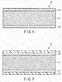
- FIG. 6 shows an axial cross-sectional view of an optical transmission element 20 including a core 21 and a cladding 22 and having no covering layer.
- FIG. 7 shows an axial cross-sectional view of an optical transmission element 30 which includes a core 21 and a cladding 22, and has a covering layer 33 including a fluorinated alkylsilane layer.
- An optical transmission element 20 having no covering layer as shown in FIG. 6 has poor durability, abrasion resistance, and lubricity.
- a fiber made of lead-free glass has higher hardness and lower flexibility in terms of physical properties than those of a lead-containing fiber. Therefore, when the tip part of the endoscope densely filled with the fiber is repeatedly severely bent, it causes the fiber to break in many cases. This leads to deterioration in the observation performance of the endoscope.
- An optical transmission element having a fluorinated alkylsilane layer 33 as shown in FIG. 7 has excellent durability, abrasion resistance, and lubricity due to the existence of the covering layer including fluorinated alkylsilane. This can reduce the breaking and deterioration to such an extent that sufficient observation performance is obtained.
- a fluorinated alkyl group in the covering layer is exposed from the surface of the optical transmission element, which disadvantageously deteriorates the adhesiveness between the plurality of optical transmission elements when the optical transmission elements are bundled.
- the plurality of optical transmission elements are bundled, and the bundle is stored in the jacket tube. Then, the end parts of the bundle are polished. As a result, the end faces of each of the optical transmission elements are polished to improve optical transparency and align the positions of the end faces of the plurality of optical transmission elements.
- the adhesiveness between the optical transmission elements having the fluorinated alkylsilane layer is low. When the adhesiveness between the optical transmission elements is low, the fixation of each of the optical transmission elements is insufficient, which makes the polishing difficult. In this case, the edge of the end faces of each optical transmission element is scraped, or some of the end faces of the optical transmission elements are buried. As a result, there is a problem that the observation performance of the endoscope is deteriorated.
- the optical transmission element according to the present invention has excellent durability, abrasion resistance and lubricity, and high adhesiveness. This enables suitable polishing.
- the image guide and light guide having excellent durability and optical transparency can be provided.
- an endoscope having excellent observation performance can be provided.
- An optical transmission element according to an embodiment was manufactured, and the durability and polishing state of the optical transmission element were evaluated.
- a nonionic surfactant was dissolved in water to prepare a treatment liquid.
- the nonionic surfactant polyoxyethylene sorbitan monooleate (20E.O.) represented by the formula 1 was used.
- the ratio of the nonionic surfactant in the treatment liquid was 1% by volume.
- An optical transmission element was produced using a fiber which is free of lead. First, a fiber was immersed into the treatment liquid prepared as described above for 10 seconds. Subsequently, the fiber was removed from the treatment liquid, and dried. In this way, an optical transmission element in which a covering layer was formed on the outer periphery of the fiber was obtained.
- the plurality of optical transmission elements produced above were collectively stored in a silicone tube. Subsequently, each end of the optical transmission elements was inserted into a ferrule, and then sealed with an adhesive, followed by cutting and polishing. In this way, a bundle of Example 1 was obtained.
- a bundle was produced in the same manner as in Example 1 except that decaglyceryl monostearate represented by the formula 2 was used as a nonionic surfactant.
- a bundle was produced in the same manner as in Example 1 except that monooleyl glyceryl ether represented by the formula 3 was used as a nonionic surfactant.
- a bundle was produced in the same manner as in Example 1 except that a fluorine-substituted alkyl group-containing organic silicon compound was used in place of a nonionic surfactant, and a treatment liquid was prepared using a fluorine-based solvent in place of water.
- the ratio of the fluorine-substituted alkyl group-containing organic silicon compound in the treatment liquid was 1% by volume.
- a bundle was produced in the same manner as in Example 1 except that myristic acid represented by the formula 4 was used in place of a nonionic surfactant, and a treatment liquid was prepared using ethanol in place of water. The ratio of myristic acid in the treatment liquid was 5% by volume.
- a bundle was produced in the same manner as in Example 1 except that palmitic acid represented by the formula 5 was used in place of a nonionic surfactant, and a treatment liquid was prepared using ethanol in place of water. The ratio of palmitic acid in the treatment liquid was 5% by volume.
- a bundle was produced in the same manner as in Example 1 except that fluorine-modified silicone oil (100% by volume) was used as a treatment liquid.
- a bundle was produced in the same manner as in Example 1 using a fiber having no covering layer.
- breaking rate % number of optical transmission elements broken after test / total number of optical transmission elements ⁇ 100
- Table 1 The evaluation results on the durability of the bundles of Examples 1 to 3 and Comparative Examples 1 to 5 are shown in Table 1.
- Table 1 a bundle having a breaking rate of less than 10% was defined as " ⁇ (very good)”.
- Table 1 also shows the number of hydroxyl groups of the nonionic surfactant used in each of Examples.
- Comparative example 1 had highly excellent durability, but it had a poor polishing state, and was not suitable for use. Comparative Examples 2, 3, and 4 using no nonionic surfactant as the covering layer had low durability, and were not suitable for use. Comparative Example 5 including no covering layer had remarkably low durability.
Landscapes
- Life Sciences & Earth Sciences (AREA)
- Physics & Mathematics (AREA)
- Chemical & Material Sciences (AREA)
- Engineering & Computer Science (AREA)
- Optics & Photonics (AREA)
- Health & Medical Sciences (AREA)
- Chemical Kinetics & Catalysis (AREA)
- General Chemical & Material Sciences (AREA)
- Geochemistry & Mineralogy (AREA)
- Materials Engineering (AREA)
- Organic Chemistry (AREA)
- General Physics & Mathematics (AREA)
- General Life Sciences & Earth Sciences (AREA)
- Surgery (AREA)
- Astronomy & Astrophysics (AREA)
- Biophysics (AREA)
- Molecular Biology (AREA)
- Radiology & Medical Imaging (AREA)
- Nuclear Medicine, Radiotherapy & Molecular Imaging (AREA)
- Biomedical Technology (AREA)
- Heart & Thoracic Surgery (AREA)
- Medical Informatics (AREA)
- Pathology (AREA)
- Animal Behavior & Ethology (AREA)
- General Health & Medical Sciences (AREA)
- Public Health (AREA)
- Veterinary Medicine (AREA)
- Endoscopes (AREA)
- Surface Treatment Of Glass Fibres Or Filaments (AREA)
- Optical Fibers, Optical Fiber Cores, And Optical Fiber Bundles (AREA)
Abstract
Description
- The present invention relates to an optical transmission element, an image guide or a light guide which includes a plurality of the optical transmission elements, an endoscope including at least one of the image guide and the light guide, and a method for manufacturing the optical transmission element.
- In a conventional endoscope, a glass optical fiber is passed through an insertion portion of the endoscope in order to secure brightness during observation. Such an optical fiber is used to transmit illumination light toward a tip part from a light source.
- The optical fiber has excellent transmissivity and light distribution properties. However, the optical fiber has high hardness and low flexibility in terms of physical properties. Since the tip part of the endoscope is repeatedly severely bent, the optical fiber is disadvantageously apt to break at the tip part. Since the endoscope is densely filled with the optical fibers, the optical fibers suffer from frictional contact also in portions other than the tip part, which disadvantageously causes the optical fibers to break. If the optical fiber in the endoscope breaks, a transmitted light amount is decreased, which causes deterioration in the observation performance of the endoscope.
- An optical transmission element as an optical fiber for solving such a problem is disclosed in Japanese Patent No.
4229890 - An object of the present invention is to provide an optical transmission element which is excellent in all respects of durability, abrasion resistance, lubricity, and adhesiveness.
- According to one aspect of the present invention, there is provided an optical transmission element comprising:
- a fiber including a core made of a first glass and a cladding made of a second glass and covering an outer periphery of the core; and
- a covering layer covering an outer periphery of the cladding and including a plurality of nonionic surfactant molecules wherein each of the nonionic surfactant molecules is hydrogen-bonded to the cladding.
- According to the present invention, there is provided an optical transmission element which maintains excellent durability, abrasion resistance and lubricity and which has excellent adhesiveness.
-
-
FIG. 1 is an axial cross-sectional view of an optical transmission element according to an embodiment. -
FIG. 2 is an axial cross-sectional view of an optical transmission element according to an embodiment, which represents a magnified view of region A surrounded with a dashed line inFIG. 1 . -
FIG. 3 shows a tip part of an endoscope according to an embodiment. -
FIG. 4 shows an image guide according to an embodiment. -
FIG. 5 is a cross-sectional view of the image guide taken along line V-V inFIG. 4 . -
FIG. 6 is an axial cross-sectional view of a conventional optical transmission element which is not covered. -
FIG. 7 is an axial cross-sectional view of a conventional optical transmission element which is covered with a fluorinated alkylsilane layer. - A first embodiment of the present invention relates to an optical transmission element.
FIG. 1 shows an axial cross-sectional view of an optical transmission element. - The optical transmission element is one used as a light waveguide for propagating a light wave, a signal, an image or the like. The optical transmission element includes, for example, an optical fiber, a light guide, an optical fiber sensor or the like. The optical transmission element may have a circular or rectangular cross-section, and the cross-section is not particularly limited.
- As shown in
FIG. 1 , anoptical transmission element 10 of the present invention includes afiber 13 and a coveringlayer 14. - The
fiber 13 mainly transmits light in theoptical transmission element 10. Thefiber 13 includes acore 11 formed in a cylindrical shape and acladding 12 covering the outer periphery of thecore 11. Both thecore 11 and thecladding 12 are made of glass. Preferably, such glass has high optical transparency. Furthermore, a first glass constituting thecore 11 preferably has a higher refractive index than that of a second glass constituting thecladding 12. As the first glass and the second glass, silica glass containing an additive can be used, for example. - The covering
layer 14 mainly protects thefiber 13 and adjusts the adhesiveness between a plurality ofoptical transmission elements 10 when theoptical transmission elements 10 are bundled. The coveringlayer 14 covers the outer periphery of thecladding 12. The thickness of the coveringlayer 14 is not particularly limited. The thickness may be 1 nm to 100 nm, and is, for example, about 10 nm. When the coveringlayer 14 is too thin, the coveringlayer 14 cannot sufficiently achieve the role of protecting the fiber. On the other hand, when the coveringlayer 14 is too thick, the ratio of the cross-sectional area of thefiber 13 to the cross-sectional area of the optical transmission element is decreased, which may cause a decrease in the transmitting efficiency of light. - The covering
layer 14 includes a plurality of nonionic surfactant molecules. The coveringlayer 14 is typically a monomolecular layer. Each of the nonionic surfactant molecules is bonded to thecladding 12 via a hydrogen bond. - A nonionic surfactant is a surfactant having a hydrophilic group which is not ionized when the surfactant is dissolved in water. The nonionic surfactant is classified into an ether type, an ester type, and other types. The nonionic surfactant used in the present embodiment preferably has a hydroxyl group as the hydrophilic group. For example, the hydroxyl group is hydrogen-bonded to the cladding to form a covering layer including the nonionic surfactant molecules on the outer periphery of the cladding.
-
FIG. 2 shows an axial cross-sectional view of an optical transmission element according to an embodiment, which represents a magnified view of region A surrounded with a dashed line inFIG. 1 . InFIG. 2 , the case where 1-0-tetradecylglycerin is used as the nonionic surfactant molecule is shown. As shown inFIG. 2 , the hydroxyl groups in the nonionic surfactant molecules are bonded to thecladding 12 via hydrogen bonds to form thecovering layer 14. - By forming such a covering
layer 14, a frictional force acting on the contact surface between the optical transmission elements can be reduced. Because of this, the durability, abrasion resistance, and lubricity of thefiber 13 can be improved. - As shown in
FIG. 2 , amicro crack 15 may exist on the outer periphery of thecladding 12. The nonionic surfactant molecule can cover such acrack 15, which can prevent the breaking of thefiber 13 caused by thecrack 15 to improve the durability of the optical transmission element. - Each of the nonionic surfactant molecules preferably has two or more hydroxyl groups. As the number of the hydroxyl groups per molecule is increased, each of the molecules is more strongly bonded to the outer periphery of the
cladding 12, and thereby it is harder for the coveringlayer 14 to be peeled off. Therefore, durability and abrasion resistance can be further improved. The number of the hydroxyl groups is preferably 12 or less, for example. When the number of the hydroxyl groups is excessively increased, the number of the hydroxyl groups which cannot be hydrogen-bonded to thecladding 12 is increased. As a result, such hydroxyl groups of the surfactant interact with each other on the outer periphery of thecladding 12, which may cause deterioration in the lubricity of thefiber 13. The number of the hydroxyl groups is more preferably 3 to 10 per molecule. - When the number of the hydroxyl groups per molecule is 2 or more, each of two or more hydroxyl groups can be bonded to the cladding so that it straddles the
micro cracks 15 which exist on the outer periphery of thecladding 12, as shown inFIG. 2 . Thereby, the effect of covering the cracks is considered to be further improved. - The nonionic surfactant molecule typically has at least one of an ether bond and an ester bond. An oxygen atom included in at least one of the ether bond and the ester bond, and a hydroxyl group of the cladding may be bonded via a hydrogen bond. The nonionic surfactant molecule preferably has any selected from hydroxyl groups, ether bonds and ester bonds in a total number of two or more in the molecule.
- The nonionic surfactant molecule may have a hydroxyl group which is not hydrogen-bonded to the hydroxyl group of the cladding. Dehydration condensation may occur between such a hydroxyl group and a hydroxyl group of the other adjacent nonionic surfactant molecule or a hydroxyl group which exists on the surface of the cladding.
- The hydrophobic group of the nonionic surfactant molecule preferably has a hydrocarbon chain having 8 carbon atoms or more. The hydrocarbon chain of the hydrophobic group may be a saturated hydrocarbon chain, or an unsaturated hydrocarbon chain. Herein, when the hydrophilic group and hydrophobic group of the nonionic surfactant molecule are separated by the ester bond, the carbon of the ester bond is not regarded as the carbon of the hydrophobic group.
- When the number of the carbon atoms of the hydrophobic group is excessively decreased, the optical transmission element may have insufficient durability, abrasion resistance, and lubricity. When the number of the carbon atoms is excessively increased, the area of the hydrocarbon chain covering the outer periphery of the
cladding 12 is increased. As a result, an adhesive and a reaction group are relatively decreased, which may cause a decrease in adhesive strength. - As the nonionic surfactant, for example, polyoxyalkylene ether, sorbitan fatty acid ester, polyoxyethylene sorbitol fatty acid ester, glyceryl ether, glycerin fatty acid ester, polyoxyethylene fatty acid ester, polyoxyethylene hardened castor oil or the like can be used. More preferable examples thereof include polyoxyethylene sorbitan monooleate (20E.O.), decaglyceryl monostearate, and monooleyl glyceryl ether.
- In a preferable embodiment, the optical transmission element includes a lead-free fiber which does not contain lead. Since detrimental substances such as lead are strictly regulated in recent years, the requirement of the lead-free fiber has been increased. However, the lead-free fiber has higher hardness and lower flexibility than those of the lead-containing fiber, which disadvantageously has low durability.
- However, the fiber is covered with the covering layer including the nonionic surfactant molecules according to the present embodiment, and thereby even the lead-free fiber can have sufficient durability, abrasion resistance, and lubricity.
- The covering layer can be formed by applying a treatment liquid containing a nonionic surfactant and water to the outer periphery of the cladding. The treatment liquid may contain other ingredients, but it may contain only a nonionic surfactant and water. The ratio of the nonionic surfactant in the treatment liquid is 0.01 to 20% by volume, for example, and preferably 0.2 to 10% by volume. When the ratio is within the range, the nonionic surfactant molecules constitute the covering layer at a suitable density, and thereby sufficient durability, abrasion resistance, and lubricity are obtained, which makes it hard for the covering layer to be peeled off. When the ratio is excessively increased, the nonionic surfactant molecules form micelle, which makes it impossible to obtain a homogeneous covering layer. This is considered to deteriorate durability, abrasion resistance, and lubricity.
- The method for applying the treatment liquid is not particularly limited. For example, the treatment liquid can be applied by a die coat method, a spray method, a dipping method, or a shower method. The die coat method refers to a method of passing a fiber through a die while supplying a coating liquid to the die to form a covering layer on the surface of the fiber. The spray method refers to a method of spraying a coating liquid on the surface of a fiber. The dipping method refers to a method of immersing a fiber into a coating liquid. The shower method refers to a method of passing a fiber through a shower of a coating liquid.
- A second embodiment of the present invention relates to an image guide, a light guide, and an endoscope using them. An example of a tip part of an
endoscope 1 according to an embodiment is shown inFIG. 3 . In theendoscope 1, animage guide 2 and alight guide 3 are inserted into a tip element 8. Aforceps port 6 used for inserting and removing a treatment tool for collecting a tissue or excising a lesion, and anozzle 7 for sending out water for cleaning lens or air for swelling a body cavity also are provided in the tip element 8. - In the
image guide 2 and thelight guide 3, a plurality of optical transmission elements according to the first embodiment are bundled. An example of theimage guide 2 is shown inFIG. 4. FIG. 5 shows a cross-sectional view of theimage guide 2 taken along line V-V inFIG. 4 . - As shown in
FIG. 5 , theimage guide 2 has a configuration in which a plurality ofoptical transmission elements 10 is bundled and the bundle is stored in ajacket tube 4. - In one embodiment, a solid lubricant may be applied to the outer periphery of each of the
optical transmission elements 10. By applying the solid lubricant, lubricity can be imparted to the optical transmission element, and thereby a frictional force acting on the contact surface between the optical transmission elements can be further reduced. - Examples of the solid lubricant include talc, boron nitride, molybdenum disulfide, a fluoride resin such as ethylene fluoride, polyacetal, and carbon graphite.
- In another embodiment, the solid lubricant may not be applied to each of the
optical transmission elements 10. That is, acovering layer 14 may exist on the outermost periphery of theoptical transmission element 10. According to the first embodiment, the optical transmission element having the coveringlayer 14 including a nonionic surfactant has sufficient durability, abrasion resistance, and lubricity, and thus desired performance can be obtained even if the solid lubricant is not applied thereto. - As shown in
FIG. 4 , theimage guide 2 comprises aferrule 5 at both the ends. Theimage guide 2 is incorporated into an endoscope by inserting theferrule 5 into a through hole provided in the tip element 8 as shown inFIG. 3 . Herein, theimage guide 2 has been described as an example, but thelight guide 3 also has the same configuration. - The optical transmission element according to the embodiment can achieve a more excellent effect than that of a conventional optical transmission element. The effect will be described below.
- An example of a conventional optical transmission element is shown in
FIG. 6 and FIG. 7. FIG. 6 shows an axial cross-sectional view of anoptical transmission element 20 including acore 21 and acladding 22 and having no covering layer.FIG. 7 shows an axial cross-sectional view of anoptical transmission element 30 which includes acore 21 and acladding 22, and has a covering layer 33 including a fluorinated alkylsilane layer. - An
optical transmission element 20 having no covering layer as shown inFIG. 6 has poor durability, abrasion resistance, and lubricity. In particular, a fiber made of lead-free glass has higher hardness and lower flexibility in terms of physical properties than those of a lead-containing fiber. Therefore, when the tip part of the endoscope densely filled with the fiber is repeatedly severely bent, it causes the fiber to break in many cases. This leads to deterioration in the observation performance of the endoscope. - An optical transmission element having a fluorinated alkylsilane layer 33 as shown in
FIG. 7 has excellent durability, abrasion resistance, and lubricity due to the existence of the covering layer including fluorinated alkylsilane. This can reduce the breaking and deterioration to such an extent that sufficient observation performance is obtained. However, a fluorinated alkyl group in the covering layer is exposed from the surface of the optical transmission element, which disadvantageously deteriorates the adhesiveness between the plurality of optical transmission elements when the optical transmission elements are bundled. - When the image guide or light guide used for the endoscope is manufactured, generally, the plurality of optical transmission elements are bundled, and the bundle is stored in the jacket tube. Then, the end parts of the bundle are polished. As a result, the end faces of each of the optical transmission elements are polished to improve optical transparency and align the positions of the end faces of the plurality of optical transmission elements. However, the adhesiveness between the optical transmission elements having the fluorinated alkylsilane layer is low. When the adhesiveness between the optical transmission elements is low, the fixation of each of the optical transmission elements is insufficient, which makes the polishing difficult. In this case, the edge of the end faces of each optical transmission element is scraped, or some of the end faces of the optical transmission elements are buried. As a result, there is a problem that the observation performance of the endoscope is deteriorated.
- On the other hand, the optical transmission element according to the present invention has excellent durability, abrasion resistance and lubricity, and high adhesiveness. This enables suitable polishing. By using such optical transmission elements, the image guide and light guide having excellent durability and optical transparency can be provided. Furthermore, by using such image guide and light guide, an endoscope having excellent observation performance can be provided.
- An optical transmission element according to an embodiment was manufactured, and the durability and polishing state of the optical transmission element were evaluated.
- A nonionic surfactant was dissolved in water to prepare a treatment liquid. As the nonionic surfactant, polyoxyethylene sorbitan monooleate (20E.O.) represented by the
formula 1 was used. The ratio of the nonionic surfactant in the treatment liquid was 1% by volume.
- An optical transmission element was produced using a fiber which is free of lead. First, a fiber was immersed into the treatment liquid prepared as described above for 10 seconds. Subsequently, the fiber was removed from the treatment liquid, and dried. In this way, an optical transmission element in which a covering layer was formed on the outer periphery of the fiber was obtained.
- The plurality of optical transmission elements produced above were collectively stored in a silicone tube. Subsequently, each end of the optical transmission elements was inserted into a ferrule, and then sealed with an adhesive, followed by cutting and polishing. In this way, a bundle of Example 1 was obtained.
- A bundle was produced in the same manner as in Example 1 except that decaglyceryl monostearate represented by the
formula 2 was used as a nonionic surfactant.
- A bundle was produced in the same manner as in Example 1 except that monooleyl glyceryl ether represented by the
formula 3 was used as a nonionic surfactant.
- A bundle was produced in the same manner as in Example 1 except that a fluorine-substituted alkyl group-containing organic silicon compound was used in place of a nonionic surfactant, and a treatment liquid was prepared using a fluorine-based solvent in place of water. The ratio of the fluorine-substituted alkyl group-containing organic silicon compound in the treatment liquid was 1% by volume.
- A bundle was produced in the same manner as in Example 1 except that myristic acid represented by the
formula 4 was used in place of a nonionic surfactant, and a treatment liquid was prepared using ethanol in place of water. The ratio of myristic acid in the treatment liquid was 5% by volume.
- A bundle was produced in the same manner as in Example 1 except that palmitic acid represented by the
formula 5 was used in place of a nonionic surfactant, and a treatment liquid was prepared using ethanol in place of water. The ratio of palmitic acid in the treatment liquid was 5% by volume.
- A bundle was produced in the same manner as in Example 1 except that fluorine-modified silicone oil (100% by volume) was used as a treatment liquid.

- A bundle was produced in the same manner as in Example 1 using a fiber having no covering layer.
- Durability was evaluated for each of the bundles of Examples 1 to 3 and Comparative Examples 1 to 5.
- For evaluation, a test was carried out by simulating a load applied when a tip part of an endoscope was repeatedly bent to manipulate the endoscope. Specifically, after a higher load than that in the case of manipulating the endoscope was repeatedly applied to each bundle a given number of times, the number of the broken optical transmission elements was counted. From the result, a breaking rate (%) was calculated according to the following formula:

- The evaluation results on the durability of the bundles of Examples 1 to 3 and Comparative Examples 1 to 5 are shown in Table 1. In Table 1, a bundle having a breaking rate of less than 10% was defined as "⊚ (very good)". A bundle having a breaking rate of 10% or more and less than 60% was defined as "○ (good)". A bundle having a breaking rate of 60% or more was defined as "× (poor)". Table 1 also shows the number of hydroxyl groups of the nonionic surfactant used in each of Examples.
- Furthermore, the end faces of the bundles of Examples 1 to 3 and Comparative Examples 1 to 5 were polished, and the states of the end faces of the polished bundles were observed. The results are shown in Table 1. In Table 1, a bundle having a usable level for the observation performance of the endoscope was evaluated as "○ (good)", and a bundle having an unusable level for the observation performance of the endoscope was evaluated as "× poor".
[Table 1] Component name Substance name Number of hydroxyl groups of active ingredient Ratio of active ingredient in treatment liquid (% by volume) Durability Polishing state Example 1 Active ingredient Polyoxyethylene sorbitan monooleate (20E.O.) 3 1 ○ ○ Solvent Water Example 2 Active ingredient Decaglyceryl monostearate 10 1 ○ ○ Solvent Water Example 3 Active ingredient Monooleyl glyceryl ether 2 1 ○ ○ Solvent Water Comparative Example 1 Active ingredient Fluorine-substituted alkyl group-containing organic silicon compound 3 1 ⊚ × Solvent Fluorine-based solvent Comparative Example 2 Active ingredient Myristic acid 1 5 × ○ Solvent Ethanol Comparative Example 3 Active ingredient Palmitic acid 1 5 × ○ Solvent Ethanol Comparative Example 4 Active ingredient Fluorine-modified silicone oil 0 100 × ○ Solvent Not applicable Comparative Example 5 Active ingredient Not applicable (No coat) - - × ○ Solvent Water - From the results shown in Table 1, the following is found. Comparative example 1 had highly excellent durability, but it had a poor polishing state, and was not suitable for use. Comparative Examples 2, 3, and 4 using no nonionic surfactant as the covering layer had low durability, and were not suitable for use. Comparative Example 5 including no covering layer had remarkably low durability.
- On the other hand, it was shown that all the Examples using the nonionic surfactants had excellent durability and polishing properties.
Claims (11)
- An optical transmission element comprising:a fiber including a core made of a first glass and a cladding made of a second glass and covering an outer periphery of the core; anda covering layer covering an outer periphery of the cladding and including a plurality of nonionic surfactant molecules wherein each of the nonionic surfactant molecules is hydrogen-bonded to the cladding.
- The optical transmission element according to claim 1, wherein the nonionic surfactant molecule has a hydroxyl group.
- The optical transmission element according to claim 2, wherein the nonionic surfactant molecule has two or more hydroxyl groups.
- The optical transmission element according to claim 2, wherein the nonionic surfactant molecule has at least one of an ether bond and an ester bond in the molecule, and the total number of the hydroxyl group, ether bond, and ester bond is 2 or more.
- The optical transmission element according to any one of claims 1 to 4, wherein the nonionic surfactant molecule has a hydrocarbon chain having 8 or more carbon atoms.
- The optical transmission element according to any one of claims 1 to 5, wherein the fiber is free of lead.
- The optical transmission element according to any one of claims 1 to 6, further comprising a solid lubricant applied to an outer periphery of the covering layer.
- An image guide wherein a plurality of the optical transmission elements according to any one of claims 1 to 7 are bundled.
- A light guide wherein a plurality of the optical transmission elements according to any one of claims 1 to 7 are bundled.
- An endoscope comprising at least one of the image guide according to claim 8 and the light guide according to claim 9.
- A method for manufacturing an optical transmission element, comprising:applying a treatment liquid containing a nonionic surfactant and water to an outer periphery of a fiber including a core made of first glass and a cladding made of second glass and covering an outer periphery of the core,wherein a ratio of the nonionic surfactant in the treatment liquid is 0.01 to 20% by volume.
Applications Claiming Priority (2)
| Application Number | Priority Date | Filing Date | Title |
|---|---|---|---|
| JP2014148923 | 2014-07-22 | ||
| PCT/JP2015/062884 WO2016013268A1 (en) | 2014-07-22 | 2015-04-28 | Light transmissive body and method for manufacturing same |
Publications (2)
| Publication Number | Publication Date |
|---|---|
| EP3173389A1 true EP3173389A1 (en) | 2017-05-31 |
| EP3173389A4 EP3173389A4 (en) | 2018-01-24 |
Family
ID=55162807
Family Applications (1)
| Application Number | Title | Priority Date | Filing Date |
|---|---|---|---|
| EP15825051.4A Withdrawn EP3173389A4 (en) | 2014-07-22 | 2015-04-28 | Light transmissive body and method for manufacturing same |
Country Status (5)
| Country | Link |
|---|---|
| US (1) | US9918620B2 (en) |
| EP (1) | EP3173389A4 (en) |
| JP (1) | JP5885897B1 (en) |
| CN (1) | CN105849062B (en) |
| WO (1) | WO2016013268A1 (en) |
Families Citing this family (4)
| Publication number | Priority date | Publication date | Assignee | Title |
|---|---|---|---|---|
| JP6450651B2 (en) * | 2015-06-17 | 2019-01-09 | オリンパス株式会社 | Optical transmission |
| US11105973B2 (en) | 2019-01-11 | 2021-08-31 | Schott Corporation | Optically enhanced high resolution image guides |
| CN112573838B (en) * | 2019-09-30 | 2023-12-26 | 肖特股份有限公司 | Optical fiber article and its production and use |
| EP4596645A4 (en) * | 2022-09-29 | 2025-12-31 | Fujifilm Corp | Coating composition for endoscopes, lubricant for endoscopes, method for manufacturing a lubricant for endoscopes, flexible tube for endoscopes and endoscope |
Family Cites Families (18)
| Publication number | Priority date | Publication date | Assignee | Title |
|---|---|---|---|---|
| JPH02141440A (en) * | 1988-11-21 | 1990-05-30 | Sumitomo Electric Ind Ltd | coated optical fiber |
| US5377293A (en) * | 1992-10-08 | 1994-12-27 | Olympus Optical Co., Ltd. | Optical fiber having multi-component core glass or a plastic core, and a coating layer |
| JP3955333B2 (en) * | 1996-11-08 | 2007-08-08 | デーエスエム アイピー アセッツ ベー.ヴェー. | Radiation-curable optical glass fiber coating composition, coated optical glass fiber, and optical glass fiber assembly |
| US6133472A (en) * | 1998-01-20 | 2000-10-17 | Alliedsignal Inc. | Fluorinated oxyvinyl compounds and methods of preparing and using same |
| US6966906B2 (en) * | 2001-06-08 | 2005-11-22 | Joe Denton Brown | Deflection mechanism for a surgical instrument, such as a laser delivery device and/or endoscope, and method of use |
| DK1488266T3 (en) * | 2002-03-28 | 2007-10-01 | Prysmian Cables & Systems Ltd | Methods for manufacturing coated optical fiber assemblies |
| US6959022B2 (en) * | 2003-01-27 | 2005-10-25 | Ceramoptec Gmbh | Multi-clad optical fiber lasers and their manufacture |
| WO2006000244A1 (en) * | 2004-06-28 | 2006-01-05 | Prysmian Cavi E Sistemi Energia S.R.L. | Cable with environmental stress cracking resistance |
| JP4229890B2 (en) | 2004-09-27 | 2009-02-25 | オリンパス株式会社 | Optical transmission |
| US20060230553A1 (en) * | 2005-04-14 | 2006-10-19 | Helmut Thullen | Process for tinting, dyeing or doping of moulded components made of transparent (co)polyamides in aqueous dye bath |
| EP1887946A2 (en) * | 2005-06-06 | 2008-02-20 | The Board Of Regents, The University Of Texas System | Oct using spectrally resolved bandwidth |
| US7496263B2 (en) * | 2007-06-07 | 2009-02-24 | Fujifilm Manfacturing U.S.A. Inc. | Thermosetting optical waveguide coating |
| US20080305255A1 (en) * | 2007-06-07 | 2008-12-11 | Fujifilm Manufacturing U.S.A. Inc. | Optical waveguide coating |
| JP2009122277A (en) * | 2007-11-13 | 2009-06-04 | Furukawa Electric Co Ltd:The | Optical fiber and optical transmission system |
| JP2010224174A (en) * | 2009-03-23 | 2010-10-07 | Fujifilm Corp | Glass fiber and optical transmission body |
| JP5857886B2 (en) * | 2012-06-11 | 2016-02-10 | 住友電気工業株式会社 | Optical fiber |
| JP5790942B2 (en) * | 2012-06-22 | 2015-10-07 | 住友電気工業株式会社 | Optical fiber |
| EP3081544B1 (en) | 2013-12-13 | 2019-04-17 | Olympus Corporation | Light transmission body |
-
2015
- 2015-04-28 EP EP15825051.4A patent/EP3173389A4/en not_active Withdrawn
- 2015-04-28 JP JP2015552696A patent/JP5885897B1/en active Active
- 2015-04-28 WO PCT/JP2015/062884 patent/WO2016013268A1/en not_active Ceased
- 2015-04-28 CN CN201580003264.5A patent/CN105849062B/en active Active
-
2016
- 2016-05-31 US US15/168,638 patent/US9918620B2/en active Active
Also Published As
| Publication number | Publication date |
|---|---|
| CN105849062A (en) | 2016-08-10 |
| US20160270644A1 (en) | 2016-09-22 |
| WO2016013268A1 (en) | 2016-01-28 |
| JP5885897B1 (en) | 2016-03-16 |
| US9918620B2 (en) | 2018-03-20 |
| JPWO2016013268A1 (en) | 2017-04-27 |
| EP3173389A4 (en) | 2018-01-24 |
| CN105849062B (en) | 2018-06-19 |
Similar Documents
| Publication | Publication Date | Title |
|---|---|---|
| EP3081544B1 (en) | Light transmission body | |
| KR102229141B1 (en) | Cable and medical hollow tube | |
| EP3173389A1 (en) | Light transmissive body and method for manufacturing same | |
| JP5762299B2 (en) | Optical imaging probe connector | |
| EP3693775A1 (en) | Intermittent connection-type optical fiber tape and manufacturing method therefor | |
| EP3878346B1 (en) | Endoscope and disposable endoscope system | |
| JP6450651B2 (en) | Optical transmission | |
| DE2513680A1 (en) | PROCESS TO INCREASE THE SHELF LIFE AND SERVICE LIFE OF AN OPTICAL FIBER BUNCH | |
| KR102184006B1 (en) | Lens for medical device and manufacturing method thereof | |
| US10852474B2 (en) | Optical fiber bundle, endoscope, and method of producing optical fiber bundle | |
| KR20050049483A (en) | Resin coated optical fiber, method of removing coating from resin coated optical fiber and process for producing optical fiber part | |
| EP3996789A1 (en) | Tubing with integrated optical fiber, medical devices, and methods thereof | |
| DE102019126259A1 (en) | Optical fiber article, its manufacture and uses | |
| JP2000155244A (en) | Coated optical fiber | |
| KR20160104547A (en) | Medical purpose cable, and method of manufacturing the same |
Legal Events
| Date | Code | Title | Description |
|---|---|---|---|
| STAA | Information on the status of an ep patent application or granted ep patent |
Free format text: STATUS: THE INTERNATIONAL PUBLICATION HAS BEEN MADE |
|
| PUAI | Public reference made under article 153(3) epc to a published international application that has entered the european phase |
Free format text: ORIGINAL CODE: 0009012 |
|
| STAA | Information on the status of an ep patent application or granted ep patent |
Free format text: STATUS: REQUEST FOR EXAMINATION WAS MADE |
|
| 17P | Request for examination filed |
Effective date: 20170130 |
|
| AK | Designated contracting states |
Kind code of ref document: A1 Designated state(s): AL AT BE BG CH CY CZ DE DK EE ES FI FR GB GR HR HU IE IS IT LI LT LU LV MC MK MT NL NO PL PT RO RS SE SI SK SM TR |
|
| AX | Request for extension of the european patent |
Extension state: BA ME |
|
| DAV | Request for validation of the european patent (deleted) | ||
| DAX | Request for extension of the european patent (deleted) | ||
| A4 | Supplementary search report drawn up and despatched |
Effective date: 20180103 |
|
| RIC1 | Information provided on ipc code assigned before grant |
Ipc: A61B 1/07 20060101ALI20171220BHEP Ipc: G02B 6/44 20060101ALI20171220BHEP Ipc: C03C 25/24 20180101AFI20171220BHEP Ipc: G02B 6/04 20060101ALI20171220BHEP Ipc: G02B 6/06 20060101ALI20171220BHEP Ipc: A61B 1/00 20060101ALI20171220BHEP Ipc: G02B 6/02 20060101ALI20171220BHEP Ipc: C03C 25/26 20180101ALI20171220BHEP Ipc: G02B 23/26 20060101ALI20171220BHEP Ipc: C03C 25/10 20180101ALI20171220BHEP |
|
| STAA | Information on the status of an ep patent application or granted ep patent |
Free format text: STATUS: THE APPLICATION IS DEEMED TO BE WITHDRAWN |
|
| 18D | Application deemed to be withdrawn |
Effective date: 20180731 |