EP3173328A1 - Leading edge with laminar flow control - Google Patents
Leading edge with laminar flow control Download PDFInfo
- Publication number
- EP3173328A1 EP3173328A1 EP15382588.0A EP15382588A EP3173328A1 EP 3173328 A1 EP3173328 A1 EP 3173328A1 EP 15382588 A EP15382588 A EP 15382588A EP 3173328 A1 EP3173328 A1 EP 3173328A1
- Authority
- EP
- European Patent Office
- Prior art keywords
- leading edge
- outer skin
- structural elements
- section according
- perforated
- Prior art date
- Legal status (The legal status is an assumption and is not a legal conclusion. Google has not performed a legal analysis and makes no representation as to the accuracy of the status listed.)
- Granted
Links
Images


Classifications
-
- B—PERFORMING OPERATIONS; TRANSPORTING
- B64—AIRCRAFT; AVIATION; COSMONAUTICS
- B64C—AEROPLANES; HELICOPTERS
- B64C21/00—Influencing air flow over aircraft surfaces by affecting boundary layer flow
- B64C21/02—Influencing air flow over aircraft surfaces by affecting boundary layer flow by use of slot, ducts, porous areas or the like
- B64C21/06—Influencing air flow over aircraft surfaces by affecting boundary layer flow by use of slot, ducts, porous areas or the like for sucking
-
- B—PERFORMING OPERATIONS; TRANSPORTING
- B64—AIRCRAFT; AVIATION; COSMONAUTICS
- B64C—AEROPLANES; HELICOPTERS
- B64C2230/00—Boundary layer controls
- B64C2230/04—Boundary layer controls by actively generating fluid flow
-
- B—PERFORMING OPERATIONS; TRANSPORTING
- B64—AIRCRAFT; AVIATION; COSMONAUTICS
- B64C—AEROPLANES; HELICOPTERS
- B64C2230/00—Boundary layer controls
- B64C2230/22—Boundary layer controls by using a surface having multiple apertures of relatively small openings other than slots
-
- Y—GENERAL TAGGING OF NEW TECHNOLOGICAL DEVELOPMENTS; GENERAL TAGGING OF CROSS-SECTIONAL TECHNOLOGIES SPANNING OVER SEVERAL SECTIONS OF THE IPC; TECHNICAL SUBJECTS COVERED BY FORMER USPC CROSS-REFERENCE ART COLLECTIONS [XRACs] AND DIGESTS
- Y02—TECHNOLOGIES OR APPLICATIONS FOR MITIGATION OR ADAPTATION AGAINST CLIMATE CHANGE
- Y02T—CLIMATE CHANGE MITIGATION TECHNOLOGIES RELATED TO TRANSPORTATION
- Y02T50/00—Aeronautics or air transport
- Y02T50/10—Drag reduction
Definitions
- the present invention refers to the configuration of a leading edge section with laminar flow control, for aircraft lifting surfaces, such as wings or stabilizers.
- An object of the present invention is to provide a leading edge design integrating a laminar flow control system, which improve aircraft performance and leading edge optimization from structural point of view, including bird impact improved performance.
- Aircraft manufacturers are continuously seeking ways of increasing aircraft performance and reducing fuel consumption.
- a significant amount of aircraft drag is caused by turbulent air flow on the aircraft exposed surfaces during flight. Near the aircraft skin the air flow is turbulent mainly due to the following reasons:
- one technique for reducing aircraft drag is to form and maintain a laminar boundary layer over the aircraft external surfaces.
- VTP vertical tail planes
- HTP horizontal tail planes
- Transition from laminar to turbulent flow is delayed by this technique, and may even occur after the 50% chord location, due to the combined effects of the local pressure gradient and Reynolds number.
- Figure 2 shows a laminarflow control system, to actuate on the boundary layer by bleeding air through a micro-perforated skin surface (3) at the leading edge (1).
- the diameter of the micro-perforations is within the range 10 - 100 microns.
- the air is ducted beneath the skin (3) through a network of chambers (2) located at the leading edge section (D-box) (1), and finally exhausted, through a main chamber or a suction duct (4).
- HLFC avoids many of the structural problems associated with LFC. It also requires a smaller and lighter suction system. These advantages make HLFC more suitable than full LFC for subsonic transport aircraft.
- the HLFC technology has also good aerodynamic performance in the fully turbulent mode, which is a significant advantage.
- This air suction system of the leading edge (1) requires a differential pressure distribution over the leading edge surface.
- This differential pressure distribution is achieved by providing chambers of different size, to obtain different pressure within each chamber, as shown more clearly in figure 2C .
- a conventional leading edge configuration with laminar flow control is formed by a micro-perforated outer skin (3), a perforated inner skin (5) and a set of transversal walls (6) fixed to outer and inner skins at specific locations to form chambers of different sizes, to create the chambers allowing air circulation through them.
- the present invention is defined in the attached independent claims, and refers to a leading edge of an aircraft wing or stabilizer (a HTP, or a VTP to obtain a leading section integrating a laminar flow control system.
- the leading edge with laminar flow control typically comprises a micro-drilled outer skin, an inner surface and a group of suction chambers formed between the outer skin and inner surface, wherein the suction chambers are arranged and dimensioned to obtain different pressure gradients over the outer wet surface of the leading edge, such as, via the micro-drilled outer skin, different suction pressures are so achieved on the wet surface of the leading edge.
- an aspect of the invention refers to a leading edge section obtained mainly from composite materials, and configured to implement a laminar flow control, which comprises a perforated outer skin shaped with an aerodynamic leading edge profile, an inner surface internally arranged with respect to the outer skin, and a plurality of suction chambers for the laminar flow control, formed between the outer skin and inner surface, such as an exterior region of the leading edge is communicated with an interior region of the leading edge through said suction chambers.
- Suction means are provided for suctioning air at the wet surface of the outer skin through the suction chambers, and towards the leading edge interior, from where it is exhausted.
- the leading edge section comprises a plurality of radial structural elements dimensioned to withstand structural loads at the leading edge. According to the invention, these radial structural elements are arranged to configure the suction chambers, together with the outer skin and the inner surface.
- the position and angle of the radial structural elements are selected to follow the direction of the most critical Bird Strike (BS) angles of impacts or trajectories, so that the structure supports more efficiently these BS events. Additionally, the radial structural elements are distributed in order to optimize the leading edge sizing process, mainly driven by stability and stiffness requirements.
- BS Bird Strike
- the radial structural elements and/or the inner surface are perforated, to communicate an exterior region of the leading edge with an interior region of the leading edge to obtain the HLFC.
- the leading edge includes a tubular element internally arranged, such as the inner surface is a part of the tubular element.
- the tubular element may have a circular or elliptical cross-sectional shape, or any other cross-sectional shape suitable for each particular implementation.
- One of the main advantages of the invention is that instead of using dedicated components to configure the suction chambers for the hybrid laminar flow control (HLFC), some traditional components of the leading edge, like the radial structural elements, are re-arranged to configure the suctions chambers for the HLFC.
- some traditional components of the leading edge like the radial structural elements, are re-arranged to configure the suctions chambers for the HLFC.
- Preferred materials for manufacturing the leading edge are:
- the structural part is formed by the radial structural elements, and the inner surface cured together and then bonded to the outer micro-perforated skin.
- Figure 3 shows a preferred example of a leading edge section (1) with a laminar flow control, comprising: a perforated outer skin (2) shaped with an aerodynamic leading edge profile, an inner surface (3) internally arranged with respect to the outer skin (2), and a plurality of suction chambers (4) formed between the outer skin and the inner surface (2,3).
- the leading edge section (1) further comprises a plurality of radial structural elements (5) configured to withstand structural loads at the leading edge.
- the radial structural elements (5) are arranged to define the suction chambers (4) together with the outer skin (2) and the inner surface (3). More in detail, each radial structural elements (5) is positioned such as one of its ends is attached to the outer skin (2) and the other end is attached to the inner surface (3), such as each suction chamber (4) is formed by two consecutive radial structural elements, a part of the outer skin (2) and part of the inner surface (3).
- the leading edge includes a tubular element (6) extending span-wise at the leading edge and placed at a central area of the leading edge (in a cross-sectional view).
- the inner surface (3) is a part of the tubular element (6), and the radial structural elements (5) are radially distributed at the leading edge, which means that they extend from a central area of the leading edge in different directions.
- Suction means (not shown) would apply suction at the interior of the leading edge.
- the inner surface (3) is perforated in order to communicate through said suction chambers (4), an exterior region of the leading edge with an interior region of the leading edge, in this case with the interior of the tubular element (6) as indicated by arrow (A).
- the radial structural elements (5) are perforated, such as the communication between the exterior of the leading edge and its interior, is obtained through them, as shown by the arrows (A).
- the suctioned air flows from one chamber to the followings chambers until it is expelled through the last one, creating in this way the required suction for HLFC.
- the radial structural elements (5) are positioned in accordance with the direction of the most critical Bird Strike (BS) angles of impact.
- BS Bird Strike
- one radial structural element is arranged such as one of its ends is attached at or near the leading edge forward point of the leading edge (7).
- figure 4 shows a preferred manufacturing technique, wherein the radial structural elements (5) and the tubular element (6) are obtained in one-shot, that is, they are cured together in the same curing cycle.
- the radial structural elements (5) and the tubular element (6) can be manufactured and assembled by means of other techniques or combination of techniques, suitable for each application.
- tubular element (6) or the radial structural elements (5) When the tubular element (6) or the radial structural elements (5) have been cured, they can be drilled after the curing process, or in an intermediate process previous to it.
- the outer skin (2) is conformed and cured separately, and then the radial structural elements (5) are bonded internally to the outer skin (2).
- the radial structural elements (5) are provided at one of its ends with flanges (5') to enlarge the interface surface with the outer skin (2).
- the free edge of each radial structural element (5) is welded to the inner surface of the outer skin (2).
- an erosion protective layer is preferably co-bonded or co-cured, with the outer skin.
- This erosion protective layer may consist of a polyurethane coating, a metallic coating or a metallic layer impregnated with resin, sealant, or adhesive on one of its surfaces.
- the leading edge section can be obtained entirely in one-shot manufacturing process, as represented in figure 5 .
- several pre-forms of CFRP (2', 4', 6') are conformed and assembled together as shown in the figure. More specifically, one outer skin pre-form (2'), one tubular element pre-form (6') and several four-sided pre-forms (4') to form the radial structural elements (5) and the suction chambers (4). Finally, the whole set of pre-forms are cured together.
Landscapes
- Engineering & Computer Science (AREA)
- Chemical & Material Sciences (AREA)
- Combustion & Propulsion (AREA)
- Aviation & Aerospace Engineering (AREA)
- Moulding By Coating Moulds (AREA)
- Structures Of Non-Positive Displacement Pumps (AREA)
Abstract
Description
- The present invention refers to the configuration of a leading edge section with laminar flow control, for aircraft lifting surfaces, such as wings or stabilizers.
- An object of the present invention is to provide a leading edge design integrating a laminar flow control system, which improve aircraft performance and leading edge optimization from structural point of view, including bird impact improved performance.
- Additionally, it is also an object of the present invention to provide a leading edge with a laminar flow control system, which components are easily accessible for their inspection and maintenance.
- Aircraft manufacturers are continuously seeking ways of increasing aircraft performance and reducing fuel consumption. One of the main factors when it comes to improving aircraft performance, is the aerodynamic drag on aircraft surfaces.
- A significant amount of aircraft drag is caused by turbulent air flow on the aircraft exposed surfaces during flight. Near the aircraft skin the air flow is turbulent mainly due to the following reasons:
- laminar flow is unstable with respect to small perturbations, and
- surface imperfections may cause early transition from laminar to turbulence.
- Since air laminar boundary layers create less friction at the aircraft surfaces than air turbulent boundary layers, one technique for reducing aircraft drag is to form and maintain a laminar boundary layer over the aircraft external surfaces.
- Laminar Flow reduces friction drag and implementation on vertical tail planes (VTP) and horizontal tail planes (HTP), would potentially lead to up to 2% aircraft drag reduction.
- Current existing methods to form and maintain a laminar flow are:
- Natural Laminar Flow (NLF) is obtained by a profile that produces a progressive pressure drop (i.e. favourable gradient) resulting in flow acceleration and a delay in transition to turbulence approximately at the point of minimum pressure.
- Laminar Flow Control (LFC) which relies on a relatively small amount of air being sucked through a perforated skin to suppress boundary layer instabilities.
- Hybrid Laminar Flow Control (HLFC) is a combination of full LFC and NLF as shown in
figure 1 , which relies on:- 1. suction being applied to the leading edge (1) 10 - 20% of the chord (i. e. ahead of the front spar), to stabilize the flow, and
- 2. a correctly profiled wing or lifting surface contour, to generate a suitable pressure gradient, thus maintaining the laminar flow aft of the suction area.
- Transition from laminar to turbulent flow, is delayed by this technique, and may even occur after the 50% chord location, due to the combined effects of the local pressure gradient and Reynolds number.
-
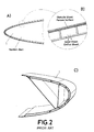
Figure 2 shows a laminarflow control system, to actuate on the boundary layer by bleeding air through a micro-perforated skin surface (3) at the leading edge (1). Typically, the diameter of the micro-perforations is within the range 10 - 100 microns. The air is ducted beneath the skin (3) through a network of chambers (2) located at the leading edge section (D-box) (1), and finally exhausted, through a main chamber or a suction duct (4). - As suction is limited to the forward part of the wing or lifting surface, HLFC avoids many of the structural problems associated with LFC. It also requires a smaller and lighter suction system. These advantages make HLFC more suitable than full LFC for subsonic transport aircraft. The HLFC technology has also good aerodynamic performance in the fully turbulent mode, which is a significant advantage.
- This air suction system of the leading edge (1) requires a differential pressure distribution over the leading edge surface. This differential pressure distribution is achieved by providing chambers of different size, to obtain different pressure within each chamber, as shown more clearly in
figure 2C . - As shown in
figure 3 , a conventional leading edge configuration with laminar flow control, is formed by a micro-perforated outer skin (3), a perforated inner skin (5) and a set of transversal walls (6) fixed to outer and inner skins at specific locations to form chambers of different sizes, to create the chambers allowing air circulation through them. - One of the main problems involved in the implementation of the HLFC technique, is that the components of the leading edge have to be manufactured separately and then assembled together. In addition to this, assembly by means of mechanical joints may reduce the effective outer suction surface. Thus, manufacturing and assembly processes of these multi-chambered structures with laminar flow control, are complicated and expensive. Furthermore, the weight penalty involved is significantly high due to the metallic materials implemented and the length of all mechanical joints used for building the leading edge, penalizing so much the aircraft performances that all HLFC benefits would be overcame and, as consequence, its implementation may be discarded
- The present invention is defined in the attached independent claims, and refers to a leading edge of an aircraft wing or stabilizer (a HTP, or a VTP to obtain a leading section integrating a laminar flow control system.
- The leading edge with laminar flow control typically comprises a micro-drilled outer skin, an inner surface and a group of suction chambers formed between the outer skin and inner surface, wherein the suction chambers are arranged and dimensioned to obtain different pressure gradients over the outer wet surface of the leading edge, such as, via the micro-drilled outer skin, different suction pressures are so achieved on the wet surface of the leading edge.
- Therefore, an aspect of the invention refers to a leading edge section obtained mainly from composite materials, and configured to implement a laminar flow control, which comprises a perforated outer skin shaped with an aerodynamic leading edge profile, an inner surface internally arranged with respect to the outer skin, and a plurality of suction chambers for the laminar flow control, formed between the outer skin and inner surface, such as an exterior region of the leading edge is communicated with an interior region of the leading edge through said suction chambers. Suction means are provided for suctioning air at the wet surface of the outer skin through the suction chambers, and towards the leading edge interior, from where it is exhausted.
- The leading edge section comprises a plurality of radial structural elements dimensioned to withstand structural loads at the leading edge. According to the invention, these radial structural elements are arranged to configure the suction chambers, together with the outer skin and the inner surface.
- The position and angle of the radial structural elements are selected to follow the direction of the most critical Bird Strike (BS) angles of impacts or trajectories, so that the structure supports more efficiently these BS events. Additionally, the radial structural elements are distributed in order to optimize the leading edge sizing process, mainly driven by stability and stiffness requirements.
- The radial structural elements and/or the inner surface are perforated, to communicate an exterior region of the leading edge with an interior region of the leading edge to obtain the HLFC.
- In one preferred embodiment, the leading edge includes a tubular element internally arranged, such as the inner surface is a part of the tubular element. The tubular element may have a circular or elliptical cross-sectional shape, or any other cross-sectional shape suitable for each particular implementation.
- One of the main advantages of the invention is that instead of using dedicated components to configure the suction chambers for the hybrid laminar flow control (HLFC), some traditional components of the leading edge, like the radial structural elements, are re-arranged to configure the suctions chambers for the HLFC.
- Preferred materials for manufacturing the leading edge are:
- 1. Carbon Fiber Reinforced Plastic (CFRP) dry carbon fiber injection (RTM).
- 2. CFRP pre-preg carbon fiber with chamber-shaped pre-forms to define the position and orientation of the spars.
- 3.- Composites and Fiber Reinforced Plastics in general, for example: fiber glass, Aramide, or hybrid combinations thereof etc.
- 4.- Metals, for example aluminum.
- With respect to the assembly process, when the leading edge is obtained from CFRP materials, preferably the structural part is formed by the radial structural elements, and the inner surface cured together and then bonded to the outer micro-perforated skin. This construction concept makes the reparability and inspection of the chambers easier with respect to conventional HLFC structural solutions.
- Some of the advantages of the invention can be summarized as follows:
- allow different material combinations for a HTP LE HLFC configuration.
- easier reparability and chambers inspection with respect to conventional HLFC structural solutions.
- allow the integration of a HTP LE HLFC configuration as structural part of a HTP.
- improvement of the structure for Bird Strike.
- sizing optimization.
- decrease of recurrent cost, compared with prior art HLFC leading edges.
- adaptability of the architecture and size of the leading edge.
- Preferred embodiments of the invention, are henceforth described with reference to the accompanying drawings, in which:
-
Figure 1 .- shows a cross-sectional view of an schematic representation of a wing or lifting surface with a hybrid laminar flow configuration according to the prior art, wherein laminar and turbulent air flow is represented with thin lines on upper and lower surfaces. -
Figure 2 .- shows a conventional multi-chamber configuration of the leading edge section of a wing or lifting surface with laminar flow control, as the one shown infigure 1 , wherein drawing (A) is a cross-sectional view, drawing (B) is an enlarged view of a detail of drawing (A), and drawing (C) is a perspective view. -
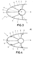
Figure 3 .- shows a schematic representation of a cross-sectional view of a preferred embodiment of a leading edge section according to the invention. The dots designate perforations positions on the inner surface. -
Figure 4 .- is a similar representation thanfigure 3 , illustrating the bonding process between the outer skin and the internal structure of the leading edge. -
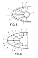
Figure 5 .- is a similar representation thanfigure 3 , illustrating the process of manufacturing the leading edge entirely in one-shot using pre-forms. The pre-forms are shown in broken lines. -
Figure 6 .- is a similar representation thanfigure 3 corresponding to another preferred embodiment of the invention. -
Figure 3 shows a preferred example of a leading edge section (1) with a laminar flow control, comprising: a perforated outer skin (2) shaped with an aerodynamic leading edge profile, an inner surface (3) internally arranged with respect to the outer skin (2), and a plurality of suction chambers (4) formed between the outer skin and the inner surface (2,3). - The leading edge section (1) further comprises a plurality of radial structural elements (5) configured to withstand structural loads at the leading edge. The radial structural elements (5) are arranged to define the suction chambers (4) together with the outer skin (2) and the inner surface (3). More in detail, each radial structural elements (5) is positioned such as one of its ends is attached to the outer skin (2) and the other end is attached to the inner surface (3), such as each suction chamber (4) is formed by two consecutive radial structural elements, a part of the outer skin (2) and part of the inner surface (3).
- In the embodiment of
figure 3 , the leading edge includes a tubular element (6) extending span-wise at the leading edge and placed at a central area of the leading edge (in a cross-sectional view). The inner surface (3) is a part of the tubular element (6), and the radial structural elements (5) are radially distributed at the leading edge, which means that they extend from a central area of the leading edge in different directions. Suction means (not shown) would apply suction at the interior of the leading edge. - Additionally in this embodiment, the inner surface (3) is perforated in order to communicate through said suction chambers (4), an exterior region of the leading edge with an interior region of the leading edge, in this case with the interior of the tubular element (6) as indicated by arrow (A).
- In the alternative embodiment of
figure 6 , instead of having a perforated inner surface, the radial structural elements (5) are perforated, such as the communication between the exterior of the leading edge and its interior, is obtained through them, as shown by the arrows (A). In this case, the suctioned air, flows from one chamber to the followings chambers until it is expelled through the last one, creating in this way the required suction for HLFC. - The radial structural elements (5) are positioned in accordance with the direction of the most critical Bird Strike (BS) angles of impact. For example, in the embodiments of
figures 3 and6 , one radial structural element is arranged such as one of its ends is attached at or near the leading edge forward point of the leading edge (7). - With respect to the method for manufacturing the leading edge,
figure 4 shows a preferred manufacturing technique, wherein the radial structural elements (5) and the tubular element (6) are obtained in one-shot, that is, they are cured together in the same curing cycle. Alternatively, the radial structural elements (5) and the tubular element (6) can be manufactured and assembled by means of other techniques or combination of techniques, suitable for each application. - When the tubular element (6) or the radial structural elements (5) have been cured, they can be drilled after the curing process, or in an intermediate process previous to it.
- The outer skin (2) is conformed and cured separately, and then the radial structural elements (5) are bonded internally to the outer skin (2). For that purpose, in the embodiment of
figure 4A , the radial structural elements (5) are provided at one of its ends with flanges (5') to enlarge the interface surface with the outer skin (2). In the alternative embodiment offigure 4B , instead of using bonded flanges, the free edge of each radial structural element (5) is welded to the inner surface of the outer skin (2). - As it can be observed in
figure 4 , one of the advantages of having the radial structural elements bonded with the outer skin, is that the outer skin could be replaced by a new one. - Since the radial structural elements are bonded with the outer skin, different materials can be used during the manufacturing process:
- Flat micro-drilled Titanium or another metal layer conformed to outer leading edge wet surface shape.
- CFRP pre-preg carbon fiber, micro-drilled after part curing cycle.
- Composites and Fiber Reinforced Plastics in general, for example: fiber glass, Aramide, or hybrid combinations thereof etc.
- Metals, for example aluminum.
- In the case of using a CFRP material, an erosion protective layer is preferably co-bonded or co-cured, with the outer skin. This erosion protective layer may consist of a polyurethane coating, a metallic coating or a metallic layer impregnated with resin, sealant, or adhesive on one of its surfaces.
- Alternatively, the leading edge section can be obtained entirely in one-shot manufacturing process, as represented in
figure 5 . In this alternative manufacturing method, several pre-forms of CFRP (2', 4', 6') are conformed and assembled together as shown in the figure. More specifically, one outer skin pre-form (2'), one tubular element pre-form (6') and several four-sided pre-forms (4') to form the radial structural elements (5) and the suction chambers (4). Finally, the whole set of pre-forms are cured together. - Other preferred embodiments of the present invention are described in the appended dependent claims and the multiple combinations of those claims.
Claims (9)
- A leading edge section with a laminar flow control comprising:a perforated outer skin shaped with an aerodynamic leading edge profile,an inner surface internally arranged with respect to the outer skin,a plurality of suction chambers formed between the outer skin and the inner surface, such as an exterior region of the leading edge is communicated with an interior region of the leading edge through said suction chambers,a plurality of radial structural elements to withstand structural loads at the leading edge, characterized in that,the radial structural elements are arranged to define the suction chambers together with the outer skin and the inner surface,and wherein the radial structural elements and/or the inner surface are perforated.
- Leading edge section according to claim 1 wherein the inner surface is perforated, such as an exterior region of the leading edge is communicated with an interior region of the leading edge through the inner surface.
- Leading edge section according to claim 1 or 2, further comprising a tubular element span-wise arranged at the leading edge, and wherein the inner surface is a part of the tubular element.
- Leading edge section according to claim 3, wherein the tubular element has perforations in correspondence with the inner surface.
- Leading edge section according to claim 1, wherein the radial structural elements are perforated, such as an exterior region of the leading edge is communicated with an interior region of the leading edge through at least some of the suctions chambers.
- Leading edge section according to any of the preceding claims, having one radial structural element arranged such as one of its ends is attached at or near the leading edge forward point of the leading edge.
- Leading edge section according to any of the preceding claims, obtained from a composite material.
- Leading edge section according to claim 7, wherein the composite material is selected from the list: Carbon Fiber Reinforced Plastic (CFRP), fiber glass, Aramide, or any combination thereof.
- Leading edge section according to any of the claims 1 to 6, wherein the leading edge is metallic.
Priority Applications (2)
| Application Number | Priority Date | Filing Date | Title |
|---|---|---|---|
| EP15382588.0A EP3173328B1 (en) | 2015-11-26 | 2015-11-26 | Leading edge with laminar flow control |
| ES15382588T ES2777280T3 (en) | 2015-11-26 | 2015-11-26 | Leading edge with laminar flow control |
Applications Claiming Priority (1)
| Application Number | Priority Date | Filing Date | Title |
|---|---|---|---|
| EP15382588.0A EP3173328B1 (en) | 2015-11-26 | 2015-11-26 | Leading edge with laminar flow control |
Publications (2)
| Publication Number | Publication Date |
|---|---|
| EP3173328A1 true EP3173328A1 (en) | 2017-05-31 |
| EP3173328B1 EP3173328B1 (en) | 2020-01-01 |
Family
ID=54838297
Family Applications (1)
| Application Number | Title | Priority Date | Filing Date |
|---|---|---|---|
| EP15382588.0A Active EP3173328B1 (en) | 2015-11-26 | 2015-11-26 | Leading edge with laminar flow control |
Country Status (2)
| Country | Link |
|---|---|
| EP (1) | EP3173328B1 (en) |
| ES (1) | ES2777280T3 (en) |
Cited By (1)
| Publication number | Priority date | Publication date | Assignee | Title |
|---|---|---|---|---|
| EP4011760A1 (en) | 2020-12-10 | 2022-06-15 | Ernst Heinrich Hirschel | Swept quasi-thin supercritical laminar wing |
Citations (7)
| Publication number | Priority date | Publication date | Assignee | Title |
|---|---|---|---|---|
| US5263667A (en) * | 1991-09-09 | 1993-11-23 | The Boeing Company | Perforated wing panel with variable porosity |
| US5366177A (en) * | 1992-10-05 | 1994-11-22 | Rockwell International Corporation | Laminar flow control apparatus for aerodynamic surfaces |
| US20100294892A1 (en) * | 2009-05-20 | 2010-11-25 | Airbus Operations Gmbh | Device for reducing the aerodynamic drag of a leading surface of an aircraft |
| EP2418147A2 (en) * | 2010-08-15 | 2012-02-15 | The Boeing Company | Laminar flow panel |
| US20130175402A1 (en) * | 2010-09-02 | 2013-07-11 | Airbus Operations Gmbh | Air sucking vehicle fuselage component, method for producing an air sucking vehicle fuselage component and a vehicle, especially an aircraft, with an air sucking vehicle fuselage component |
| US20140021304A1 (en) * | 2010-04-12 | 2014-01-23 | Airbus Operations Gmbh | Profile plate portion for use as an outer wall of a flow body, method for manufacturing a profile plate portion and flow body component comprising a suction-extraction device for fluid |
| US20150183513A1 (en) * | 2013-12-18 | 2015-07-02 | Airbus Operations Gmbh | Flow body, method for manufacturing a flow body and aircraft having such a flow body |
-
2015
- 2015-11-26 ES ES15382588T patent/ES2777280T3/en active Active
- 2015-11-26 EP EP15382588.0A patent/EP3173328B1/en active Active
Patent Citations (7)
| Publication number | Priority date | Publication date | Assignee | Title |
|---|---|---|---|---|
| US5263667A (en) * | 1991-09-09 | 1993-11-23 | The Boeing Company | Perforated wing panel with variable porosity |
| US5366177A (en) * | 1992-10-05 | 1994-11-22 | Rockwell International Corporation | Laminar flow control apparatus for aerodynamic surfaces |
| US20100294892A1 (en) * | 2009-05-20 | 2010-11-25 | Airbus Operations Gmbh | Device for reducing the aerodynamic drag of a leading surface of an aircraft |
| US20140021304A1 (en) * | 2010-04-12 | 2014-01-23 | Airbus Operations Gmbh | Profile plate portion for use as an outer wall of a flow body, method for manufacturing a profile plate portion and flow body component comprising a suction-extraction device for fluid |
| EP2418147A2 (en) * | 2010-08-15 | 2012-02-15 | The Boeing Company | Laminar flow panel |
| US20130175402A1 (en) * | 2010-09-02 | 2013-07-11 | Airbus Operations Gmbh | Air sucking vehicle fuselage component, method for producing an air sucking vehicle fuselage component and a vehicle, especially an aircraft, with an air sucking vehicle fuselage component |
| US20150183513A1 (en) * | 2013-12-18 | 2015-07-02 | Airbus Operations Gmbh | Flow body, method for manufacturing a flow body and aircraft having such a flow body |
Cited By (1)
| Publication number | Priority date | Publication date | Assignee | Title |
|---|---|---|---|---|
| EP4011760A1 (en) | 2020-12-10 | 2022-06-15 | Ernst Heinrich Hirschel | Swept quasi-thin supercritical laminar wing |
Also Published As
| Publication number | Publication date |
|---|---|
| ES2777280T3 (en) | 2020-08-04 |
| EP3173328B1 (en) | 2020-01-01 |
Similar Documents
| Publication | Publication Date | Title |
|---|---|---|
| US10532807B2 (en) | Leading edge with laminar flow control and manufacturing method thereof | |
| EP3159259B1 (en) | Leading edge with laminar flow control and manufacturing method thereof | |
| EP2891606B1 (en) | Flow body, method for manufacturing a flow body and aircraft having such a flow body | |
| EP2914487B1 (en) | Natural laminar flow wingtip | |
| US10836472B2 (en) | One-piece composite bifurcated winglet | |
| EP2810870B1 (en) | Efficient fluid dynamic and structural design and integration method to achieve extended hybrid laminar flow control | |
| US10384766B2 (en) | Aircraft wing roughness strip and method | |
| CN106043669A (en) | System and method for enhancing high-lift performance of aircraft | |
| EP2844555A1 (en) | Morphing aerofoil | |
| US20190202566A1 (en) | Leading edge struction for a flow control system of an aircraft | |
| US10953624B2 (en) | Aircraft airfoil having a stitched trailing edge and manufacturing method thereof | |
| CN107054612A (en) | Form the trailing edge of aerodynamics airfoil and the device including blower system | |
| CN104724279A (en) | Leading Edge For An Aircraft Lifting Surface | |
| CN108100222A (en) | The lifting surface for being used to increase generated lifting force of aircraft | |
| US10377464B2 (en) | Method, injection moulding tool for manufacturing a leading edge section with hybrid laminar flow control for an aircraft, and leading edge section with hybrid laminar flow control obtained thereof | |
| EP3173328B1 (en) | Leading edge with laminar flow control | |
| US9745053B2 (en) | Aerodynamic component and method for producing an aerodynamic component | |
| EP2610170A1 (en) | Air drag reduction for an undercarriage with skids of a rotary wing aircraft | |
| EP3020631B1 (en) | Aerodynamic component and method for producing an aerodynamic component | |
| CN205019729U (en) | Removable wing fence wing tip composite set of model aeroplane and model ship aircraft | |
| CN112224385B (en) | An aircraft elevator and an aircraft horizontal tail with a T-shaped microstructure | |
| KR101927339B1 (en) | Tail boom of a rotorcraft, and rotorcraft |
Legal Events
| Date | Code | Title | Description |
|---|---|---|---|
| PUAI | Public reference made under article 153(3) epc to a published international application that has entered the european phase |
Free format text: ORIGINAL CODE: 0009012 |
|
| STAA | Information on the status of an ep patent application or granted ep patent |
Free format text: STATUS: THE APPLICATION HAS BEEN PUBLISHED |
|
| AK | Designated contracting states |
Kind code of ref document: A1 Designated state(s): AL AT BE BG CH CY CZ DE DK EE ES FI FR GB GR HR HU IE IS IT LI LT LU LV MC MK MT NL NO PL PT RO RS SE SI SK SM TR |
|
| AX | Request for extension of the european patent |
Extension state: BA ME |
|
| STAA | Information on the status of an ep patent application or granted ep patent |
Free format text: STATUS: REQUEST FOR EXAMINATION WAS MADE |
|
| 17P | Request for examination filed |
Effective date: 20171009 |
|
| RBV | Designated contracting states (corrected) |
Designated state(s): AL AT BE BG CH CY CZ DE DK EE ES FI FR GB GR HR HU IE IS IT LI LT LU LV MC MK MT NL NO PL PT RO RS SE SI SK SM TR |
|
| STAA | Information on the status of an ep patent application or granted ep patent |
Free format text: STATUS: EXAMINATION IS IN PROGRESS |
|
| 17Q | First examination report despatched |
Effective date: 20180416 |
|
| GRAP | Despatch of communication of intention to grant a patent |
Free format text: ORIGINAL CODE: EPIDOSNIGR1 |
|
| STAA | Information on the status of an ep patent application or granted ep patent |
Free format text: STATUS: GRANT OF PATENT IS INTENDED |
|
| INTG | Intention to grant announced |
Effective date: 20191015 |
|
| GRAS | Grant fee paid |
Free format text: ORIGINAL CODE: EPIDOSNIGR3 |
|
| GRAA | (expected) grant |
Free format text: ORIGINAL CODE: 0009210 |
|
| STAA | Information on the status of an ep patent application or granted ep patent |
Free format text: STATUS: THE PATENT HAS BEEN GRANTED |
|
| AK | Designated contracting states |
Kind code of ref document: B1 Designated state(s): AL AT BE BG CH CY CZ DE DK EE ES FI FR GB GR HR HU IE IS IT LI LT LU LV MC MK MT NL NO PL PT RO RS SE SI SK SM TR |
|
| REG | Reference to a national code |
Ref country code: GB Ref legal event code: FG4D |
|
| REG | Reference to a national code |
Ref country code: CH Ref legal event code: EP Ref country code: AT Ref legal event code: REF Ref document number: 1219492 Country of ref document: AT Kind code of ref document: T Effective date: 20200115 |
|
| REG | Reference to a national code |
Ref country code: IE Ref legal event code: FG4D |
|
| REG | Reference to a national code |
Ref country code: DE Ref legal event code: R096 Ref document number: 602015044582 Country of ref document: DE |
|
| REG | Reference to a national code |
Ref country code: NL Ref legal event code: MP Effective date: 20200101 |
|
| REG | Reference to a national code |
Ref country code: LT Ref legal event code: MG4D |
|
| PG25 | Lapsed in a contracting state [announced via postgrant information from national office to epo] |
Ref country code: NO Free format text: LAPSE BECAUSE OF FAILURE TO SUBMIT A TRANSLATION OF THE DESCRIPTION OR TO PAY THE FEE WITHIN THE PRESCRIBED TIME-LIMIT Effective date: 20200401 Ref country code: RS Free format text: LAPSE BECAUSE OF FAILURE TO SUBMIT A TRANSLATION OF THE DESCRIPTION OR TO PAY THE FEE WITHIN THE PRESCRIBED TIME-LIMIT Effective date: 20200101 Ref country code: LT Free format text: LAPSE BECAUSE OF FAILURE TO SUBMIT A TRANSLATION OF THE DESCRIPTION OR TO PAY THE FEE WITHIN THE PRESCRIBED TIME-LIMIT Effective date: 20200101 Ref country code: FI Free format text: LAPSE BECAUSE OF FAILURE TO SUBMIT A TRANSLATION OF THE DESCRIPTION OR TO PAY THE FEE WITHIN THE PRESCRIBED TIME-LIMIT Effective date: 20200101 Ref country code: PT Free format text: LAPSE BECAUSE OF FAILURE TO SUBMIT A TRANSLATION OF THE DESCRIPTION OR TO PAY THE FEE WITHIN THE PRESCRIBED TIME-LIMIT Effective date: 20200527 Ref country code: NL Free format text: LAPSE BECAUSE OF FAILURE TO SUBMIT A TRANSLATION OF THE DESCRIPTION OR TO PAY THE FEE WITHIN THE PRESCRIBED TIME-LIMIT Effective date: 20200101 Ref country code: CZ Free format text: LAPSE BECAUSE OF FAILURE TO SUBMIT A TRANSLATION OF THE DESCRIPTION OR TO PAY THE FEE WITHIN THE PRESCRIBED TIME-LIMIT Effective date: 20200101 |
|
| REG | Reference to a national code |
Ref country code: ES Ref legal event code: FG2A Ref document number: 2777280 Country of ref document: ES Kind code of ref document: T3 Effective date: 20200804 |
|
| PG25 | Lapsed in a contracting state [announced via postgrant information from national office to epo] |
Ref country code: BG Free format text: LAPSE BECAUSE OF FAILURE TO SUBMIT A TRANSLATION OF THE DESCRIPTION OR TO PAY THE FEE WITHIN THE PRESCRIBED TIME-LIMIT Effective date: 20200401 Ref country code: LV Free format text: LAPSE BECAUSE OF FAILURE TO SUBMIT A TRANSLATION OF THE DESCRIPTION OR TO PAY THE FEE WITHIN THE PRESCRIBED TIME-LIMIT Effective date: 20200101 Ref country code: SE Free format text: LAPSE BECAUSE OF FAILURE TO SUBMIT A TRANSLATION OF THE DESCRIPTION OR TO PAY THE FEE WITHIN THE PRESCRIBED TIME-LIMIT Effective date: 20200101 Ref country code: IS Free format text: LAPSE BECAUSE OF FAILURE TO SUBMIT A TRANSLATION OF THE DESCRIPTION OR TO PAY THE FEE WITHIN THE PRESCRIBED TIME-LIMIT Effective date: 20200501 Ref country code: HR Free format text: LAPSE BECAUSE OF FAILURE TO SUBMIT A TRANSLATION OF THE DESCRIPTION OR TO PAY THE FEE WITHIN THE PRESCRIBED TIME-LIMIT Effective date: 20200101 Ref country code: GR Free format text: LAPSE BECAUSE OF FAILURE TO SUBMIT A TRANSLATION OF THE DESCRIPTION OR TO PAY THE FEE WITHIN THE PRESCRIBED TIME-LIMIT Effective date: 20200402 |
|
| REG | Reference to a national code |
Ref country code: DE Ref legal event code: R097 Ref document number: 602015044582 Country of ref document: DE |
|
| PG25 | Lapsed in a contracting state [announced via postgrant information from national office to epo] |
Ref country code: RO Free format text: LAPSE BECAUSE OF FAILURE TO SUBMIT A TRANSLATION OF THE DESCRIPTION OR TO PAY THE FEE WITHIN THE PRESCRIBED TIME-LIMIT Effective date: 20200101 Ref country code: SK Free format text: LAPSE BECAUSE OF FAILURE TO SUBMIT A TRANSLATION OF THE DESCRIPTION OR TO PAY THE FEE WITHIN THE PRESCRIBED TIME-LIMIT Effective date: 20200101 Ref country code: DK Free format text: LAPSE BECAUSE OF FAILURE TO SUBMIT A TRANSLATION OF THE DESCRIPTION OR TO PAY THE FEE WITHIN THE PRESCRIBED TIME-LIMIT Effective date: 20200101 Ref country code: SM Free format text: LAPSE BECAUSE OF FAILURE TO SUBMIT A TRANSLATION OF THE DESCRIPTION OR TO PAY THE FEE WITHIN THE PRESCRIBED TIME-LIMIT Effective date: 20200101 Ref country code: EE Free format text: LAPSE BECAUSE OF FAILURE TO SUBMIT A TRANSLATION OF THE DESCRIPTION OR TO PAY THE FEE WITHIN THE PRESCRIBED TIME-LIMIT Effective date: 20200101 |
|
| PLBE | No opposition filed within time limit |
Free format text: ORIGINAL CODE: 0009261 |
|
| STAA | Information on the status of an ep patent application or granted ep patent |
Free format text: STATUS: NO OPPOSITION FILED WITHIN TIME LIMIT |
|
| REG | Reference to a national code |
Ref country code: AT Ref legal event code: MK05 Ref document number: 1219492 Country of ref document: AT Kind code of ref document: T Effective date: 20200101 |
|
| 26N | No opposition filed |
Effective date: 20201002 |
|
| PG25 | Lapsed in a contracting state [announced via postgrant information from national office to epo] |
Ref country code: AT Free format text: LAPSE BECAUSE OF FAILURE TO SUBMIT A TRANSLATION OF THE DESCRIPTION OR TO PAY THE FEE WITHIN THE PRESCRIBED TIME-LIMIT Effective date: 20200101 Ref country code: IT Free format text: LAPSE BECAUSE OF FAILURE TO SUBMIT A TRANSLATION OF THE DESCRIPTION OR TO PAY THE FEE WITHIN THE PRESCRIBED TIME-LIMIT Effective date: 20200101 |
|
| PG25 | Lapsed in a contracting state [announced via postgrant information from national office to epo] |
Ref country code: PL Free format text: LAPSE BECAUSE OF FAILURE TO SUBMIT A TRANSLATION OF THE DESCRIPTION OR TO PAY THE FEE WITHIN THE PRESCRIBED TIME-LIMIT Effective date: 20200101 Ref country code: SI Free format text: LAPSE BECAUSE OF FAILURE TO SUBMIT A TRANSLATION OF THE DESCRIPTION OR TO PAY THE FEE WITHIN THE PRESCRIBED TIME-LIMIT Effective date: 20200101 |
|
| REG | Reference to a national code |
Ref country code: DE Ref legal event code: R119 Ref document number: 602015044582 Country of ref document: DE |
|
| PG25 | Lapsed in a contracting state [announced via postgrant information from national office to epo] |
Ref country code: MC Free format text: LAPSE BECAUSE OF FAILURE TO SUBMIT A TRANSLATION OF THE DESCRIPTION OR TO PAY THE FEE WITHIN THE PRESCRIBED TIME-LIMIT Effective date: 20200101 |
|
| REG | Reference to a national code |
Ref country code: CH Ref legal event code: PL |
|
| GBPC | Gb: european patent ceased through non-payment of renewal fee |
Effective date: 20201126 |
|
| PG25 | Lapsed in a contracting state [announced via postgrant information from national office to epo] |
Ref country code: LU Free format text: LAPSE BECAUSE OF NON-PAYMENT OF DUE FEES Effective date: 20201126 |
|
| REG | Reference to a national code |
Ref country code: BE Ref legal event code: MM Effective date: 20201130 |
|
| PG25 | Lapsed in a contracting state [announced via postgrant information from national office to epo] |
Ref country code: LI Free format text: LAPSE BECAUSE OF NON-PAYMENT OF DUE FEES Effective date: 20201130 Ref country code: CH Free format text: LAPSE BECAUSE OF NON-PAYMENT OF DUE FEES Effective date: 20201130 |
|
| PG25 | Lapsed in a contracting state [announced via postgrant information from national office to epo] |
Ref country code: FR Free format text: LAPSE BECAUSE OF NON-PAYMENT OF DUE FEES Effective date: 20201130 Ref country code: IE Free format text: LAPSE BECAUSE OF NON-PAYMENT OF DUE FEES Effective date: 20201126 |
|
| PG25 | Lapsed in a contracting state [announced via postgrant information from national office to epo] |
Ref country code: DE Free format text: LAPSE BECAUSE OF NON-PAYMENT OF DUE FEES Effective date: 20210601 Ref country code: GB Free format text: LAPSE BECAUSE OF NON-PAYMENT OF DUE FEES Effective date: 20201126 |
|
| REG | Reference to a national code |
Ref country code: ES Ref legal event code: FD2A Effective date: 20220202 |
|
| PG25 | Lapsed in a contracting state [announced via postgrant information from national office to epo] |
Ref country code: TR Free format text: LAPSE BECAUSE OF FAILURE TO SUBMIT A TRANSLATION OF THE DESCRIPTION OR TO PAY THE FEE WITHIN THE PRESCRIBED TIME-LIMIT Effective date: 20200101 Ref country code: MT Free format text: LAPSE BECAUSE OF FAILURE TO SUBMIT A TRANSLATION OF THE DESCRIPTION OR TO PAY THE FEE WITHIN THE PRESCRIBED TIME-LIMIT Effective date: 20200101 Ref country code: ES Free format text: LAPSE BECAUSE OF NON-PAYMENT OF DUE FEES Effective date: 20201127 Ref country code: CY Free format text: LAPSE BECAUSE OF FAILURE TO SUBMIT A TRANSLATION OF THE DESCRIPTION OR TO PAY THE FEE WITHIN THE PRESCRIBED TIME-LIMIT Effective date: 20200101 |
|
| PG25 | Lapsed in a contracting state [announced via postgrant information from national office to epo] |
Ref country code: MK Free format text: LAPSE BECAUSE OF FAILURE TO SUBMIT A TRANSLATION OF THE DESCRIPTION OR TO PAY THE FEE WITHIN THE PRESCRIBED TIME-LIMIT Effective date: 20200101 Ref country code: AL Free format text: LAPSE BECAUSE OF FAILURE TO SUBMIT A TRANSLATION OF THE DESCRIPTION OR TO PAY THE FEE WITHIN THE PRESCRIBED TIME-LIMIT Effective date: 20200101 |
|
| PG25 | Lapsed in a contracting state [announced via postgrant information from national office to epo] |
Ref country code: BE Free format text: LAPSE BECAUSE OF NON-PAYMENT OF DUE FEES Effective date: 20201130 |