EP3173024B1 - Dental radiography device - Google Patents
Dental radiography device Download PDFInfo
- Publication number
- EP3173024B1 EP3173024B1 EP14891572.1A EP14891572A EP3173024B1 EP 3173024 B1 EP3173024 B1 EP 3173024B1 EP 14891572 A EP14891572 A EP 14891572A EP 3173024 B1 EP3173024 B1 EP 3173024B1
- Authority
- EP
- European Patent Office
- Prior art keywords
- voltage
- voltage transformer
- secondary coil
- ray
- dental
- Prior art date
- Legal status (The legal status is an assumption and is not a legal conclusion. Google has not performed a legal analysis and makes no representation as to the accuracy of the status listed.)
- Active
Links
Images




Classifications
-
- A—HUMAN NECESSITIES
- A61—MEDICAL OR VETERINARY SCIENCE; HYGIENE
- A61B—DIAGNOSIS; SURGERY; IDENTIFICATION
- A61B6/00—Apparatus or devices for radiation diagnosis; Apparatus or devices for radiation diagnosis combined with radiation therapy equipment
- A61B6/50—Apparatus or devices for radiation diagnosis; Apparatus or devices for radiation diagnosis combined with radiation therapy equipment specially adapted for specific body parts; specially adapted for specific clinical applications
- A61B6/51—Apparatus or devices for radiation diagnosis; Apparatus or devices for radiation diagnosis combined with radiation therapy equipment specially adapted for specific body parts; specially adapted for specific clinical applications for dentistry
-
- A—HUMAN NECESSITIES
- A61—MEDICAL OR VETERINARY SCIENCE; HYGIENE
- A61B—DIAGNOSIS; SURGERY; IDENTIFICATION
- A61B6/00—Apparatus or devices for radiation diagnosis; Apparatus or devices for radiation diagnosis combined with radiation therapy equipment
- A61B6/44—Constructional features of apparatus for radiation diagnosis
- A61B6/4405—Constructional features of apparatus for radiation diagnosis the apparatus being movable or portable, e.g. handheld or mounted on a trolley
-
- A—HUMAN NECESSITIES
- A61—MEDICAL OR VETERINARY SCIENCE; HYGIENE
- A61B—DIAGNOSIS; SURGERY; IDENTIFICATION
- A61B6/00—Apparatus or devices for radiation diagnosis; Apparatus or devices for radiation diagnosis combined with radiation therapy equipment
- A61B6/46—Arrangements for interfacing with the operator or the patient
- A61B6/461—Displaying means of special interest
-
- H—ELECTRICITY
- H05—ELECTRIC TECHNIQUES NOT OTHERWISE PROVIDED FOR
- H05G—X-RAY TECHNIQUE
- H05G1/00—X-ray apparatus involving X-ray tubes; Circuits therefor
- H05G1/08—Electrical details
- H05G1/10—Power supply arrangements for feeding the X-ray tube
-
- H—ELECTRICITY
- H05—ELECTRIC TECHNIQUES NOT OTHERWISE PROVIDED FOR
- H05G—X-RAY TECHNIQUE
- H05G1/00—X-ray apparatus involving X-ray tubes; Circuits therefor
- H05G1/08—Electrical details
- H05G1/10—Power supply arrangements for feeding the X-ray tube
- H05G1/12—Power supply arrangements for feeding the X-ray tube with DC or rectified single-phase AC or double-phase
-
- A—HUMAN NECESSITIES
- A61—MEDICAL OR VETERINARY SCIENCE; HYGIENE
- A61B—DIAGNOSIS; SURGERY; IDENTIFICATION
- A61B6/00—Apparatus or devices for radiation diagnosis; Apparatus or devices for radiation diagnosis combined with radiation therapy equipment
- A61B6/40—Arrangements for generating radiation specially adapted for radiation diagnosis
-
- A—HUMAN NECESSITIES
- A61—MEDICAL OR VETERINARY SCIENCE; HYGIENE
- A61B—DIAGNOSIS; SURGERY; IDENTIFICATION
- A61B6/00—Apparatus or devices for radiation diagnosis; Apparatus or devices for radiation diagnosis combined with radiation therapy equipment
- A61B6/56—Details of data transmission or power supply, e.g. use of slip rings
Definitions
- the present invention relates to a dental radiography device and, more particularly, to a dental radiography device that can reduce an exposure dose and battery consumption by reducing an exposure time by using a high switching frequency of 100kHz or more, that prevents malfunction due to sudden high voltage, that can easily set an X-ray radiation time in accordance with teeth, and that can be reduced in size and weight and can be used safely, accurately, and conveniently.
- a medical radiography device which radiates X-rays to a human body and detects a difference in energy intensity distribution of the X-rays, falls into an analog type and a digital type.
- the analog type which uses an intensifying screen (fluorescent plate) and a silver halide film, makes a latent image on the silver halide film using light from the intensifying screen and then obtains a visual image by chemically processing the silver halide film.
- an intensifying screen fluorescent plate
- a silver halide film makes a latent image on the silver halide film using light from the intensifying screen and then obtains a visual image by chemically processing the silver halide film.
- costs are continuously generated, the film needs to be carefully managed, and waste water deteriorates the environment of a hospital.
- the digital type which uses a 2D sensor as a detector responding to X-rays, obtains a minute electrical signal generated by the sensor through a 2D matrix, converts an amplified signal into a digital value using an amplifying circuit that amplifies the minute signal, and an analog/digital converter makes an image data from the digital value and then displays an image through a monitor or a printout after performing appropriate imaging processing.
- Digital radiography devices are used in dentistry to diagnose teeth and check whether prostheses have been correctly installed.
- a "Portable digital X-ray system” has been disclosed in KR 20020008810 A .
- the system in the cited publication can be mounted with a vehicle, unlike a fixed type of the related art, but cannot be easily carried by a user.
- KR 20050090667 A has proposed an apparatus of which the material and the mechanical configuration have been manufactured to be carried, but it does not consider the radiation time or the exposure dose of X-rays, so a patient is exposed to X-rays for too much time and it is inconvenient to use the apparatus due to heavy weight.
- KR 20080005000 A has proposed a configuration that connects one or more diode in parallel to improve tube voltage and tube current ripples by improving a switching frequency and apply load corresponding to momentary load to a side of a diode where voltage is firstly applied in a multiplier circuit including a plurality of condenser and diodes connected to each other, in order to be applied to an X-ray generator of 100kHz as a way of reducing an exposure dose.
- dental radiograph devices of the related art cannot be simply operated for patients, so it is required to further reduce the size and weight and ergonomically design the devices to conveniently use them for a longer period of time for patients.
- X-ray sources are known from WO 95/20241 A1 and US 5,023,768 A .
- JP 2002 065657 A discloses and X-ray source which may have a battery.
- the present invention aims at providing an alternative dental X-ray imaging device for portable use, which has a low X-ray exposure dose, is able to operate accurately and stably without error and has an increased lifespan.
- the present invention provides a dental radiography device comprising the features of claim 1.
- Advantageous embodiments are indicated in further claims.
- the high-voltage transformer may include: a hollow bobbin having, around an outer side, a blocking wall separating a primary coil and a secondary coil and a plurality of separation walls for ensuring a plurality of spaces for winding the secondary coil, the blocking wall and the separation wall spaced from each other perpendicular to a shaft; the primary and the secondary coils wound around the bobbin; and primary coil and secondary coil connection terminals formed at the bobbin so that an input/output terminal of the primary coil and an input/output terminal of the secondary coil are separated, in which the primary coil and the secondary coil may not interfere with each other.
- a high-voltage multiplying circuit at a side of the high-voltage transformer has an overvoltage protection circuit in which a plurality of pairs of diodes and condensers is connected in parallel and two or more diodes are connected in series to an end of the first diode at an end of the high-voltage multiplying circuit, that is, at an output side of the high-voltage transformer, so accurate tube voltage can be provided.
- X-ray radiation times are set within 0.01 to 0.2s and recorded in a memory in accordance with teeth, and when a user selects a desired tooth to scan through a display unit and an input unit on a case, an exposure time is automatically adjusted in accordance with the selection.
- the present invention it is possible to reduce ripples using a high-frequency inverter having a switching frequency of 100kHz or more and reduce a rising time and a falling time when radiating X-rays, so appropriate tube voltage is generated right after power is supplied. Accordingly, the exposure dose can be largely reduced and the exposure dose to a human body can be decreased, so deterioration in performance of the electronic device can be reduced.
- a primary coil and the secondary coil do not interfere with each other, so voltage from a power supply can be stably boosted and wiring is easy, and thus it can be commercially used.
- charging is required every time even though a frequency of 45kHz is used in the related art, but the device of the present invention can be used hundreds of times even using 100kHz, so the device can be used for two or more days in common dental clinics without charging.
- the focal spot of the device is small, so high-quality images can be obtained.
- the entire size of the device can be reduced, so it is possible to provide a device of about 1.7kg or less, and accordingly, the device can be operated even by women without difficulty.
- a dental radiography device includes a power supply outputting electricity of 10C to 20C, a switching unit outputting a high-frequency signal by switching output values from overvoltage and overcurrent to 100kHz to 10THz, a high-voltage transformer amplifying a signal from the switching unit, and a high-voltage multiplier circuit converting output voltage from the high-voltage transformer into boosting voltage or DC voltage and including an overvoltage protection circuit.
- the radiography device largely includes a case 10 capable of being held by hand and having an X-ray radiation hole 12, an X-ray generator 20 disposed inside the case 10 and generating X-rays in response to a signal from the outside, an X-ray guide 30 guiding the X-rays from the X-ray generator 20 to the outside through the X-ray radiation hole 12, and a cap 40 covering an end of the X-ray guide 30.
- various parts for gripping and operating the radiograph device in the case 10 including a display 13 for showing images, various control knobs N1 ⁇ N3 for controlling operation to make the X-ray generator 20 generate X-rays, an input unit including a touch panel, and a handgrip 14 for holding the device with hands during scanning.
- the X-ray generator 20 includes, as shown in FIGS. 1 and 2 , a housing 21 that is made of aluminum, is plated with a material (for example, lead) that blocks X-rays and is easily soldered, on the inner side, and houses an X-ray tube for generating X-rays, a filament transformer for supplying power to a filament in the X-ray tube, a high-voltage multiplier circuit, and a high-voltage transformer, and is filled with insulating oil, an X-ray radiation tube 22 formed at a side of the housing 21 and preventing diffusion of X-rays, and a power supply 25 disposed on a side of the housing 21 to supply power to the housing 21.
- a housing 21 that is made of aluminum, is plated with a material (for example, lead) that blocks X-rays and is easily soldered, on the inner side, and houses an X-ray tube for generating X-rays, a filament transformer for supplying power to a filament in the X
- the X-ray tube 12 as shown in FIG. 2 , has a discharge hole 23b formed at a side of the aluminum tube 12a filled with insulating oil and blocked by transparent nylon resin (an acryl plate), a high-vacuum glass pipe 23c disposed in the aluminum tube 23a, and an electron generator 23d and an X-ray generating unit 23e disposed in the high-vacuum glass pipe 23c.
- the electron generator 23d is electrically connected to a cathode (-) and has a focusing electrode 23d-1 having a tungsten filament therein. Electrons discharged from the tungsten filament in the focusing electrode 23d-1 are accelerated by high voltage applied to a cathode and an anode in high-vacuum pipe and hit against a target 23e-1 of the X-ray generating unit 23e facing the cathode.
- the X-ray generating unit 23e includes a stator 23e-1 at the outside, a rotary 23e-3 at the inside, and the target 23e-1 connected to a side of the rotary 23e-3 through a shaft.
- the X-ray generating unit 23e is connected to the anode (+) and current flowing through a coil C wounding around the stator 23e-2 rotates the rotor 23e-3 by generating an electromagnetic force, so the target 23e-1 connected to a side of the rotor 23e-3 through a shaft is also rotated.
- a process of setting coils in the high-voltage transformer T is described with reference to FIGS. 3 and 4 .
- a primary coil 110 and a secondary coil 120 are wound around a bobbin B and completely separated by a blocking wall 130, with an input/output terminal 112 of the primary coil 110 and an input/output terminal 122 of the secondary coil 120 separated so that the primary coil 110 and the secondary coil 120 do not interfere with each other, thereby boosting voltage applied from the power supply.
- the secondary coil 120 has a wire diameter of 0.08mm to 0.085mm, but when the wire diameter is under 0.08mm, desired output voltage cannot be obtained, and when the wire diameter is over 0.085mm, the size of the high-voltage transformer increases.
- the secondary coils are sequentially wound in a plurality of spaces divided by the separation walls 124 in accordance with a predetermined number of windings and slits 126 for passing the secondary coils are formed in the separation walls 124 to connect the secondary coils 120 in the spaces.
- a core is inserted into the bobbin B with the coils wound, an L value is measured with an LCR meter and whether the L value is within a predetermined range is checked, and the bobbin and the core are primarily fixed by taping and secondarily, the joint of two cores is bonded.
- the high-voltage transformer of the present invention is small, 3cm or less in size.
- the high-voltage transformer T is disposed adjacent to the high-voltage multiplier circuit 200, as shown in FIG. 5 , and a plurality of holes 220 is formed through a substrate 210 where the high-voltage transformer and the high-voltage multiplier circuit are disposed to pass the insulating oil, in which a hole 220 is formed in each condenser C.
- diodes D and D1 and condensers C are disposed in parallel at the output side of the high-voltage transformer T, and one or more diodes D2 for protection against overvoltage are connected in series to then ends of the diodes D1 at the end of the high-voltage multiplier circuit, that is, the output side of the high-voltage transformer so that the circuit can be protected from overvoltage and accurate tube voltage can be provided.
- the power supply 25 is formed by connecting two or more module type power supplies 350 in series, as shown in FIGS. 7 and 8 , in which insulation papers 320 are disposed at both sides of a thin film anode 310 made of copper and a plurality of thin power units 340 formed by stacking thin film cathodes 330 made of aluminum is stacked with an insulating paper (not shown) therebetween, so the power supply 25 can stably output a large amount of electricity (10C) over 100 number of times in a small size.
- a focal spot of the radiography device means the focus size of a target, and the smaller the focal spot, the higher the quality of an image that can be obtained.
- Domestic products have a 0.8mm focal spot and the present invention provides a high-quality image using a focal spot of 0.4mm.
- the dental radiography device largely includes: a tube voltage generator 410 generating necessary tube voltage (60kV ⁇ 70kV); a tube current generator 420 generating tube current (1mA ⁇ 2mA), a switching unit 430 transmitting the tube voltage and the tube current to a high-voltage transformer T and filament transformer T1 in accordance with a predetermined switching frequency; a high-voltage multiplier circuit 200 multiplying the high-voltage transformer T and the filament transformer T1, which are connected to the rear end of the switching unit 430 and transmit voltage to the X-ray tube 440, by a predetermined value and transmitting the voltage to the X-ray tube 440; a detecting/checking unit 450 detects an error by detecting tube voltage, tube current, and temperature of the radiography device and outputs a result based on the error; an input unit 460 for selecting various operations of the radiography device; a display unit 13 displaying various operation states; and a control unit 470 controlling the components in
- the tube current generator 420 includes a pulse width modulator (PWM) circuit and an oscillator and sets tube current a predetermined value inputted within a predetermined range (1 to 3mA) by adjusting output from the pulse width modulator (PWM) within a predetermined range.
- PWM pulse width modulator
- the tube voltage generator 410 also includes a pulse width modulator (PWM) and an oscillator, makes PWM output within 100kHz to 10tHz, and sets tube voltage to a predetermined level within a predetermined range (60 to 70kV).
- PWM pulse width modulator
- an oscillator makes PWM output within 100kHz to 10tHz, and sets tube voltage to a predetermined level within a predetermined range (60 to 70kV).
- the detecting/checking unit 450 detects tube voltage and tube current, compares their maximum and minimum values (MAX & MIN) and transmits the result to the control unit 470, and determines whether the internal temperature of the housing 21 is within a predetermined range (50°C to 55°C) and transmits the result to the control unit 470, and detects and checks various operation states and transmits the results to the control unit.
- MAX & MIN maximum and minimum values
- the high-voltage transformer T is operated at a predetermined switching frequency (100kHz to 10THz) and applies boosted output voltage to the high-voltage multiplying circuit 200.
- the high-voltage multiplying circuit 200 (positive & negative operation) is composed of a plurality of diodes (high-voltage diode: 12kV or more) and capacitors (high-voltage capacitor : 15kV or more) and disposed in parallel at the output terminal of the high-voltage transformer, converts output from the high-voltage transformer into boosting voltage and DC voltage in each step in accordance with positive/negative operation, and produces and supplies output voltage to the X-ray tube by operating by two times, eight times, or sixteen times.
- the radiography device of the present invention When the radiography device of the present invention was operated at a switching frequency of 120kHz, as shown in FIG. 11 , an excellent image could be obtained, the time taken to obtain the image was 0.01 to 0.2s, which is much shorter than 0.35 to 0.7s when the switching frequency was 40kHz in the related art, and a clear image could be obtained.
- the predetermined voltage for operating the device cannot be reached and image cannot be obtained, and when it exceeds 0.2s, unnecessary exposure is made and there is no reason to continue the operation.
- an exposure dose per hour at 120kHz was 1.2 ⁇ SV, which was largely reduced as compared with the exposure dose per hour of 0.03mSV at 45kHz in the related art and which is a little higher than the exposure dose of 0.14 ⁇ SV generated in the nature.
- the dental radiography can scan all teeth within 0.01 to 0.2s , so radiation times are set within 0.01 to 0.2s and recorded in a memory, depending on teeth (teeth of a child and an adult, and a cheek tooth, and a canine tooth) . Further, when a user selects a desired tooth to scan through the display unit and the output unit on the case, the exposure time is automatically adjusted in accordance with the selection.
- the radiography device of the present invention has a high switching frequency, the size of the high-voltage transformer reduces and the battery structure is improved. Accordingly, as shown in FIG. 12 , the entire size of the radiography device is largely decreased and the weight is small, about 1.7kg, as compared with radiography devices of the related art, so the radiography device can be operated even by women without difficulty.
Landscapes
- Health & Medical Sciences (AREA)
- Life Sciences & Earth Sciences (AREA)
- Engineering & Computer Science (AREA)
- Medical Informatics (AREA)
- Biomedical Technology (AREA)
- Surgery (AREA)
- High Energy & Nuclear Physics (AREA)
- Physics & Mathematics (AREA)
- Nuclear Medicine, Radiotherapy & Molecular Imaging (AREA)
- Optics & Photonics (AREA)
- Pathology (AREA)
- Radiology & Medical Imaging (AREA)
- Veterinary Medicine (AREA)
- Heart & Thoracic Surgery (AREA)
- Molecular Biology (AREA)
- Biophysics (AREA)
- Animal Behavior & Ethology (AREA)
- General Health & Medical Sciences (AREA)
- Public Health (AREA)
- Dentistry (AREA)
- Oral & Maxillofacial Surgery (AREA)
- Power Engineering (AREA)
- Human Computer Interaction (AREA)
- Apparatus For Radiation Diagnosis (AREA)
- X-Ray Techniques (AREA)
Description
- The present invention relates to a dental radiography device and, more particularly, to a dental radiography device that can reduce an exposure dose and battery consumption by reducing an exposure time by using a high switching frequency of 100kHz or more, that prevents malfunction due to sudden high voltage, that can easily set an X-ray radiation time in accordance with teeth, and that can be reduced in size and weight and can be used safely, accurately, and conveniently.
- In general, a medical radiography device, which radiates X-rays to a human body and detects a difference in energy intensity distribution of the X-rays, falls into an analog type and a digital type.
- The analog type, which uses an intensifying screen (fluorescent plate) and a silver halide film, makes a latent image on the silver halide film using light from the intensifying screen and then obtains a visual image by chemically processing the silver halide film. In the process of developing, costs are continuously generated, the film needs to be carefully managed, and waste water deteriorates the environment of a hospital.
- On the other hand, the digital type, which uses a 2D sensor as a detector responding to X-rays, obtains a minute electrical signal generated by the sensor through a 2D matrix, converts an amplified signal into a digital value using an amplifying circuit that amplifies the minute signal, and an analog/digital converter makes an image data from the digital value and then displays an image through a monitor or a printout after performing appropriate imaging processing.
- Digital radiography devices are used in dentistry to diagnose teeth and check whether prostheses have been correctly installed. Related thereto, a "Portable digital X-ray system" has been disclosed in
KR 20020008810 A -
KR 20050090667 A -
KR 20080005000 A - However, arranging diodes in parallel to protect them from overcurrent is not actually needed because the current range used for X-rays is low and narrow. Further, a temporary peak voltage is generated at the output port of a high-voltage transformer and accordingly X-rays cannot be accurately controlled, so obtained images are dim or milky white and the lifespan of an apparatus may be reduced. Accordingly, it is required to maintain a predetermined voltage without overvoltage.
- Further, increasing a switching voltage causes a problem with insulation, but the configurations described above do not consider this insulation problem, so complete insulation is strongly required.
- Further, dental radiograph devices of the related art cannot be simply operated for patients, so it is required to further reduce the size and weight and ergonomically design the devices to conveniently use them for a longer period of time for patients.
- Further, it has been reported that the more dental X-ray treatments a patient receives, the larger the danger of thyroid gland-related disease becomes, maximally by five times (by Dr. Anjum Memon, Brighton-sussex medical college, U.K), but X-ray generators using high frequencies use a switching frequency of 40kHz or less in our country, so ripples are large and a rising time and a falling time are long, which increases an X-ray exposure dose, and accordingly, it is an urgent need to solve this problem. Further, since electronic parts are also reduced in lifespan when they are exposed to X-rays for a long period of time, it is difficult to use expensive equipment for a long period of time.
- Further X-ray sources are known from
WO 95/20241 A1 US 5,023,768 A .JP 2002 065657 A - The present invention aims at providing an alternative dental X-ray imaging device for portable use, which has a low X-ray exposure dose, is able to operate accurately and stably without error and has an increased lifespan.
- In order to achieve this object, the present invention provides a dental radiography device comprising the features of
claim 1. Advantageous embodiments are indicated in further claims. - The high-voltage transformer may include: a hollow bobbin having, around an outer side, a blocking wall separating a primary coil and a secondary coil and a plurality of separation walls for ensuring a plurality of spaces for winding the secondary coil, the blocking wall and the separation wall spaced from each other perpendicular to a shaft; the primary and the secondary coils wound around the bobbin; and primary coil and secondary coil connection terminals formed at the bobbin so that an input/output terminal of the primary coil and an input/output terminal of the secondary coil are separated, in which the primary coil and the secondary coil may not interfere with each other.
- A high-voltage multiplying circuit at a side of the high-voltage transformer has an overvoltage protection circuit in which a plurality of pairs of diodes and condensers is connected in parallel and two or more diodes are connected in series to an end of the first diode at an end of the high-voltage multiplying circuit, that is, at an output side of the high-voltage transformer, so accurate tube voltage can be provided.
- A plurality of holes, including holes for each condenser, is formed in a board where the high-voltage multiplying circuit and insulating oil is injected through the holes, so insulating effect is improved and a current leakage is prevented.
- Further, X-ray radiation times are set within 0.01 to 0.2s and recorded in a memory in accordance with teeth, and when a user selects a desired tooth to scan through a display unit and an input unit on a case, an exposure time is automatically adjusted in accordance with the selection.
- A power supply formed by connecting a plurality of module type power supplies in series in which insulating papers are disposed at both sides of a thin film anode made of copper and a plurality of thin film power units formed by stacking thin film cathodes made of aluminum is stacked, so the power supply despite being in small in size can output a large amount of electricity over 100 number of times in a small size.
- According to the present invention, it is possible to reduce ripples using a high-frequency inverter having a switching frequency of 100kHz or more and reduce a rising time and a falling time when radiating X-rays, so appropriate tube voltage is generated right after power is supplied. Accordingly, the exposure dose can be largely reduced and the exposure dose to a human body can be decreased, so deterioration in performance of the electronic device can be reduced.
- Further, it is possible to protect a circuit from overvoltage suddenly generated by a high-voltage multiplying circuit and obtain accurate output voltage, so scanning can be accurately performed.
- Further, by improving the structure of a high-voltage transformer, a primary coil and the secondary coil do not interfere with each other, so voltage from a power supply can be stably boosted and wiring is easy, and thus it can be commercially used.
- Further, charging is required every time even though a frequency of 45kHz is used in the related art, but the device of the present invention can be used hundreds of times even using 100kHz, so the device can be used for two or more days in common dental clinics without charging.
- Further, the focal spot of the device is small, so high-quality images can be obtained.
- Further, by reducing the size of the arrangement structure of the high-voltage transformer and the high-voltage multiplying circuit and the power supply, the entire size of the device can be reduced, so it is possible to provide a device of about 1.7kg or less, and accordingly, the device can be operated even by women without difficulty.
-
-
FIG. 1 is an exploded perspective view showing a dental radiograph device according to the present invention. -
FIG. 2 is a cross-sectional view showing an X-ray tube. -
FIG. 3 is a view showing a coil winding structure of a high-voltage transformer of the present invention. -
FIG. 4 is a view showing the actual size of a high-voltage transformer of the present invention. -
FIG. 5 is a view showing an example of arrangement of a high-voltage transformer and a multiplier circuit. -
FIG. 6 is a view showing a configuration for preventing overvoltage in a high-voltage multiplier circuit. -
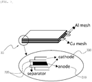
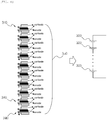
FIGS. 7 and8 are views showing the configuration of a power supply. -
FIGS. 9 and10 are views showing an electrical configuration of a radiography device of the present invention. -
FIG. 11 is a view showing X-ray images by the present invention and the related art. -
FIG. 12 is a view showing the size of a radiography device of the present invention. - Hereinafter, embodiments of the present invention will be described with reference to the accompanying drawings.
- A dental radiography device according to the present invention includes a power supply outputting electricity of 10C to 20C, a switching unit outputting a high-frequency signal by switching output values from overvoltage and overcurrent to 100kHz to 10THz, a high-voltage transformer amplifying a signal from the switching unit, and a high-voltage multiplier circuit converting output voltage from the high-voltage transformer into boosting voltage or DC voltage and including an overvoltage protection circuit.
- Referring to
FIG. 1 , the radiography device largely includes acase 10 capable of being held by hand and having anX-ray radiation hole 12, anX-ray generator 20 disposed inside thecase 10 and generating X-rays in response to a signal from the outside, anX-ray guide 30 guiding the X-rays from theX-ray generator 20 to the outside through theX-ray radiation hole 12, and acap 40 covering an end of theX-ray guide 30. - In this configuration, there are provided various parts for gripping and operating the radiograph device in the
case 10, including adisplay 13 for showing images, various control knobs N1 ∼ N3 for controlling operation to make theX-ray generator 20 generate X-rays, an input unit including a touch panel, and ahandgrip 14 for holding the device with hands during scanning. - The
X-ray generator 20 includes, as shown inFIGS. 1 and2 , ahousing 21 that is made of aluminum, is plated with a material (for example, lead) that blocks X-rays and is easily soldered, on the inner side, and houses an X-ray tube for generating X-rays, a filament transformer for supplying power to a filament in the X-ray tube, a high-voltage multiplier circuit, and a high-voltage transformer, and is filled with insulating oil, anX-ray radiation tube 22 formed at a side of thehousing 21 and preventing diffusion of X-rays, and apower supply 25 disposed on a side of thehousing 21 to supply power to thehousing 21. - The
X-ray tube 12, as shown inFIG. 2 , has adischarge hole 23b formed at a side of the aluminum tube 12a filled with insulating oil and blocked by transparent nylon resin (an acryl plate), a high-vacuum glass pipe 23c disposed in thealuminum tube 23a, and anelectron generator 23d and anX-ray generating unit 23e disposed in the high-vacuum glass pipe 23c. - The
electron generator 23d is electrically connected to a cathode (-) and has a focusingelectrode 23d-1 having a tungsten filament therein. Electrons discharged from the tungsten filament in the focusingelectrode 23d-1 are accelerated by high voltage applied to a cathode and an anode in high-vacuum pipe and hit against atarget 23e-1 of theX-ray generating unit 23e facing the cathode. - The
X-ray generating unit 23e includes astator 23e-1 at the outside, a rotary 23e-3 at the inside, and thetarget 23e-1 connected to a side of the rotary 23e-3 through a shaft. TheX-ray generating unit 23e is connected to the anode (+) and current flowing through a coil C wounding around thestator 23e-2 rotates therotor 23e-3 by generating an electromagnetic force, so thetarget 23e-1 connected to a side of therotor 23e-3 through a shaft is also rotated. - In the X-ray tube 23 having this configuration, when electrons discharged from the focusing
electrode 23d-1 hit against therotating target 23e-1, X-rays are generated, and some of the X-rays are discharged out of the tube through thedischarge hole 23b whereas the other is blocked. - A process of setting coils in the high-voltage transformer T is described with reference to
FIGS. 3 and4 . First, aprimary coil 110 and asecondary coil 120 are wound around a bobbin B and completely separated by ablocking wall 130, with an input/output terminal 112 of theprimary coil 110 and an input/output terminal 122 of thesecondary coil 120 separated so that theprimary coil 110 and thesecondary coil 120 do not interfere with each other, thereby boosting voltage applied from the power supply. - The
secondary coil 120 has a wire diameter of 0.08mm to 0.085mm, but when the wire diameter is under 0.08mm, desired output voltage cannot be obtained, and when the wire diameter is over 0.085mm, the size of the high-voltage transformer increases. The secondary coils are sequentially wound in a plurality of spaces divided by theseparation walls 124 in accordance with a predetermined number of windings andslits 126 for passing the secondary coils are formed in theseparation walls 124 to connect thesecondary coils 120 in the spaces. - A core is inserted into the bobbin B with the coils wound, an L value is measured with an LCR meter and whether the L value is within a predetermined range is checked, and the bobbin and the core are primarily fixed by taping and secondarily, the joint of two cores is bonded.
- The high-voltage transformer of the present invention is small, 3cm or less in size.
- The high-voltage transformer T is disposed adjacent to the high-
voltage multiplier circuit 200, as shown inFIG. 5 , and a plurality ofholes 220 is formed through asubstrate 210 where the high-voltage transformer and the high-voltage multiplier circuit are disposed to pass the insulating oil, in which ahole 220 is formed in each condenser C. - On the high-
voltage multiplier circuit 200, as shown inFIGS. 5 and6 , diodes D and D1 and condensers C are disposed in parallel at the output side of the high-voltage transformer T, and one or more diodes D2 for protection against overvoltage are connected in series to then ends of the diodes D1 at the end of the high-voltage multiplier circuit, that is, the output side of the high-voltage transformer so that the circuit can be protected from overvoltage and accurate tube voltage can be provided. - The
power supply 25 is formed by connecting two or more moduletype power supplies 350 in series, as shown inFIGS. 7 and8 , in whichinsulation papers 320 are disposed at both sides of athin film anode 310 made of copper and a plurality ofthin power units 340 formed by stackingthin film cathodes 330 made of aluminum is stacked with an insulating paper (not shown) therebetween, so thepower supply 25 can stably output a large amount of electricity (10C) over 100 number of times in a small size. - A focal spot of the radiography device means the focus size of a target, and the smaller the focal spot, the higher the quality of an image that can be obtained. Domestic products have a 0.8mm focal spot and the present invention provides a high-quality image using a focal spot of 0.4mm.
- The electrical configuration of the radiography device of the present invention having this configuration is described with reference to
FIGS. 9 and10 . - As shown in
FIG. 9 , the dental radiography device according to the present invention largely includes: atube voltage generator 410 generating necessary tube voltage (60kV ∼ 70kV); a tubecurrent generator 420 generating tube current (1mA ∼ 2mA), aswitching unit 430 transmitting the tube voltage and the tube current to a high-voltage transformer T and filament transformer T1 in accordance with a predetermined switching frequency; a high-voltage multiplier circuit 200 multiplying the high-voltage transformer T and the filament transformer T1, which are connected to the rear end of theswitching unit 430 and transmit voltage to theX-ray tube 440, by a predetermined value and transmitting the voltage to theX-ray tube 440; a detecting/checkingunit 450 detects an error by detecting tube voltage, tube current, and temperature of the radiography device and outputs a result based on the error; aninput unit 460 for selecting various operations of the radiography device; adisplay unit 13 displaying various operation states; and acontrol unit 470 controlling the components in the radiograph device in response to signals from theinput unit 460 and the detecting/checkingunit 450. - The tube
current generator 420 includes a pulse width modulator (PWM) circuit and an oscillator and sets tube current a predetermined value inputted within a predetermined range (1 to 3mA) by adjusting output from the pulse width modulator (PWM) within a predetermined range. - Further, the
tube voltage generator 410 also includes a pulse width modulator (PWM) and an oscillator, makes PWM output within 100kHz to 10tHz, and sets tube voltage to a predetermined level within a predetermined range (60 to 70kV). - The detecting/checking
unit 450 detects tube voltage and tube current, compares their maximum and minimum values (MAX & MIN) and transmits the result to thecontrol unit 470, and determines whether the internal temperature of thehousing 21 is within a predetermined range (50°C to 55°C) and transmits the result to thecontrol unit 470, and detects and checks various operation states and transmits the results to the control unit. - The high-voltage transformer T is operated at a predetermined switching frequency (100kHz to 10THz) and applies boosted output voltage to the high-
voltage multiplying circuit 200. - The high-voltage multiplying circuit 200 (positive & negative operation) is composed of a plurality of diodes (high-voltage diode: 12kV or more) and capacitors (high-voltage capacitor : 15kV or more) and disposed in parallel at the output terminal of the high-voltage transformer, converts output from the high-voltage transformer into boosting voltage and DC voltage in each step in accordance with positive/negative operation, and produces and supplies output voltage to the X-ray tube by operating by two times, eight times, or sixteen times.
- When the radiography device of the present invention was operated at a switching frequency of 120kHz, as shown in
FIG. 11 , an excellent image could be obtained, the time taken to obtain the image was 0.01 to 0.2s, which is much shorter than 0.35 to 0.7s when the switching frequency was 40kHz in the related art, and a clear image could be obtained. - When the scanning time is less than 0.01s, the predetermined voltage for operating the device cannot be reached and image cannot be obtained, and when it exceeds 0.2s, unnecessary exposure is made and there is no reason to continue the operation.
- Further, since scanning was possible within a short time, an exposure dose per hour at 120kHz was 1.2µSV, which was largely reduced as compared with the exposure dose per hour of 0.03mSV at 45kHz in the related art and which is a little higher than the exposure dose of 0.14µSV generated in the nature.
- The dental radiography can scan all teeth within 0.01 to 0.2s , so radiation times are set within 0.01 to 0.2s and recorded in a memory, depending on teeth (teeth of a child and an adult, and a cheek tooth, and a canine tooth) . Further, when a user selects a desired tooth to scan through the display unit and the output unit on the case, the exposure time is automatically adjusted in accordance with the selection.
- Since the radiography device of the present invention has a high switching frequency, the size of the high-voltage transformer reduces and the battery structure is improved. Accordingly, as shown in
FIG. 12 , the entire size of the radiography device is largely decreased and the weight is small, about 1.7kg, as compared with radiography devices of the related art, so the radiography device can be operated even by women without difficulty.
Claims (6)
- A dental radiograph device comprising:an X-ray tube (12) including a filament and configured to generate X-rays;a high-voltage transformer (T) configured to operate at a switching frequency of 100kHz to 10THz and to amplify input signals by using a power supply (25) configured to output electricity of 10C to 20C, said high-voltage transformer (T) being wound with a primary coil (110) and a secondary coil (120) without interference with each other, the secondary coil (120) having a wire diameter of 0.08mm to 0.085mm;a filament transformer configured to supply power to the filament in the X-ray tube (12);a high-voltage multiplying circuit (200) including an overvoltage protection circuit and configured to convert output voltage from the high-voltage transformer (T) into a boosting voltage or DC voltage; andwherein said power supply (25) is formed by connecting a plurality of module type power supplies (350) in series, in which insulating papers are disposed at both sides of a thin film anode (310) made of copper, and a plurality of thin film power units (340) formed by stacking thin film cathodes (330) made of aluminum is stacked therebetween, andwherein said device is configured to provide X-ray radiation times of 0.01 to 0.2s.
- The dental radiograph device of claim 1, wherein the high-voltage transformer (T) includes a hollow bobbin (B) having, around an outer side, a blocking wall (130) separating the primary coil (110) and the secondary coil (120) and a plurality of separation walls (124) for ensuring a plurality of spaces for winding the secondary coil (120), the blocking wall (130) and the separation wall (124) spaced from each other perpendicular to a shaft;
the primary and the secondary coils (110, 120) are wound around the bobbin (B); and
primary coil and secondary coil connection terminals are formed at the bobbin (B) so that an input/output terminal (112) of the primary coil (110) and an input/output terminal (112) of the secondary coil (122) are separated. - The dental radiography device of claim 1, wherein the high-voltage multiplying circuit (200) has diodes (D, D1) and condensers (C) arranged in parallel at an output side of the high-voltage transformer (T) and two or more diodes (D2) for protection from overvoltage are connected in series to ends of the diodes at the output side of the high-voltage transformer (T), that is, an end of the high-voltage multiplying circuit (200).
- The dental radiography device of claim 2 or 3, wherein a board where the high-voltage transformer (T) and the high-voltage multiplying circuit (200) are disposed adjacent to each other has a plurality of holes (220) including holes formed at positions corresponding to condensers (C) for insulating oil to be injected through the holes (220).
- The dental radiography device of one of claims 1 to 4, configured for recording X-ray radiation times in a memory in accordance with teeth, and when a user selects a desired tooth to scan through a display unit and an input unit on a case, the X-ray radiation time is set in accordance with the selection.
- The dental radiography device of one of claims 1 to 5, wherein the X-ray tube (12) is 10mm to 56mm long and has a focal spot of 0.01µm to 0.4mm.
Applications Claiming Priority (2)
| Application Number | Priority Date | Filing Date | Title |
|---|---|---|---|
| KR1020140055916A KR101427555B1 (en) | 2014-05-09 | 2014-05-09 | X-ray device to reduce the weight and Radiation Exposure |
| PCT/KR2014/008297 WO2015170804A1 (en) | 2014-05-09 | 2014-09-04 | Dental radiography device |
Publications (3)
| Publication Number | Publication Date |
|---|---|
| EP3173024A1 EP3173024A1 (en) | 2017-05-31 |
| EP3173024A4 EP3173024A4 (en) | 2018-02-21 |
| EP3173024B1 true EP3173024B1 (en) | 2019-06-12 |
Family
ID=51749814
Family Applications (1)
| Application Number | Title | Priority Date | Filing Date |
|---|---|---|---|
| EP14891572.1A Active EP3173024B1 (en) | 2014-05-09 | 2014-09-04 | Dental radiography device |
Country Status (5)
| Country | Link |
|---|---|
| US (1) | US9788805B2 (en) |
| EP (1) | EP3173024B1 (en) |
| KR (1) | KR101427555B1 (en) |
| CN (1) | CN106456103B (en) |
| WO (1) | WO2015170804A1 (en) |
Families Citing this family (9)
| Publication number | Priority date | Publication date | Assignee | Title |
|---|---|---|---|---|
| US10556129B2 (en) * | 2015-10-02 | 2020-02-11 | Varian Medical Systems, Inc. | Systems and methods for treating a skin condition using radiation |
| KR101684400B1 (en) * | 2016-03-11 | 2016-12-08 | 주식회사 뷰레이 | Portable carbon nanotube and filament type X-ray device |
| KR101867318B1 (en) | 2016-11-23 | 2018-06-15 | (주)이림전자 | X-ray module assembly for a portable X-ray device |
| KR102343120B1 (en) | 2016-11-24 | 2021-12-29 | (주)덱스코윈 | Potable X-ray Generator |
| CN109363712A (en) * | 2018-12-07 | 2019-02-22 | 余姚德诚科技咨询有限公司 | Ray projection time sets platform |
| CN109874219B (en) * | 2019-03-29 | 2024-01-30 | 珠海西格医疗设备有限公司 | Dental X-ray machine and packaging method thereof |
| TWI782418B (en) * | 2021-02-09 | 2022-11-01 | 能資國際股份有限公司 | Method and device for driving high-voltage electron radiation tube with positive and negative pulses |
| US11589447B2 (en) * | 2021-04-07 | 2023-02-21 | Energy Resources International Co., Ltd. | Driving device for driving a high-voltage X ray tube and method thereof driving the same |
| KR102717370B1 (en) * | 2023-09-11 | 2024-10-15 | 주식회사 티인테크놀로지 | Tube current control device installable on x-ray generator |
Family Cites Families (13)
| Publication number | Priority date | Publication date | Assignee | Title |
|---|---|---|---|---|
| US5023768A (en) * | 1989-11-24 | 1991-06-11 | Varian Associates, Inc. | High voltage high power DC power supply |
| US5428658A (en) * | 1994-01-21 | 1995-06-27 | Photoelectron Corporation | X-ray source with flexible probe |
| JP4569995B2 (en) * | 2000-09-05 | 2010-10-27 | 株式会社日立メディコ | X-ray CT system |
| US7448801B2 (en) * | 2002-02-20 | 2008-11-11 | Inpho, Inc. | Integrated X-ray source module |
| CN1751543B (en) * | 2003-02-20 | 2011-02-02 | 因普有限公司 | Integrated X-ray source module |
| KR20060068624A (en) * | 2004-12-16 | 2006-06-21 | (주)덱스코윈 | Portable radiation screening device |
| KR100806833B1 (en) * | 2006-07-07 | 2008-02-22 | 주식회사 카이론테크놀로지 | Power Supply of Portable X-Ray Generator |
| JP5076639B2 (en) * | 2007-05-22 | 2012-11-21 | 日産自動車株式会社 | Secondary battery and vehicle equipped with the same |
| KR100941125B1 (en) * | 2007-11-23 | 2010-02-10 | (주)덱스코윈 | Portable oral imaging device |
| CN101765290B (en) * | 2009-12-07 | 2012-12-26 | 芜湖国睿兆伏电子股份有限公司 | High-voltage generator used for X-ray machine and control method thereof |
| CN103200755A (en) * | 2012-01-06 | 2013-07-10 | 通用电气公司 | Power generation system, X-ray emitter system and power generation system packaging |
| KR101404004B1 (en) * | 2012-09-21 | 2014-06-13 | (주)덱스코윈 | Apparatus for Display of X-ray Photograping Area of Potable type |
| KR200467938Y1 (en) | 2012-11-16 | 2013-07-12 | 권영배 | High voltage tube tank of portable x-ray generator |
-
2014
- 2014-05-09 KR KR1020140055916A patent/KR101427555B1/en active Active
- 2014-09-04 CN CN201480079876.8A patent/CN106456103B/en active Active
- 2014-09-04 EP EP14891572.1A patent/EP3173024B1/en active Active
- 2014-09-04 US US14/894,333 patent/US9788805B2/en active Active
- 2014-09-04 WO PCT/KR2014/008297 patent/WO2015170804A1/en not_active Ceased
Non-Patent Citations (1)
| Title |
|---|
| None * |
Also Published As
| Publication number | Publication date |
|---|---|
| CN106456103B (en) | 2019-09-03 |
| EP3173024A1 (en) | 2017-05-31 |
| US20170049409A1 (en) | 2017-02-23 |
| EP3173024A4 (en) | 2018-02-21 |
| KR101427555B1 (en) | 2014-08-07 |
| WO2015170804A1 (en) | 2015-11-12 |
| US9788805B2 (en) | 2017-10-17 |
| CN106456103A (en) | 2017-02-22 |
Similar Documents
| Publication | Publication Date | Title |
|---|---|---|
| US9788805B2 (en) | Dental raidography device | |
| KR102118862B1 (en) | X-ray generating apparatus having field emission x-ray source | |
| EP1600044B1 (en) | Integrated x-ray source module | |
| US7448801B2 (en) | Integrated X-ray source module | |
| US6169782B1 (en) | X-ray system with internal power supply including battery power and capacitively stored power | |
| US20020003408A1 (en) | Pulsed high voltage radiography system power supply having a one-to-one correspondence between low voltage input pulses and high voltage output pulses. | |
| US12156320B2 (en) | X-ray machine head and image device | |
| JP5562341B2 (en) | Battery type X-ray imaging apparatus | |
| US7672432B2 (en) | X-ray machine and related voltage generator | |
| KR102471534B1 (en) | X-ray generator | |
| US12267939B2 (en) | X-ray generating apparatus | |
| EP2823502A1 (en) | Compact x-ray sources for moderate loading with x-ray tube with carbon nanotube cathode | |
| CN106664787A (en) | High voltage generator and method for supplying an X-ray tube | |
| CN1751543B (en) | Integrated X-ray source module | |
| CN109429418A (en) | X-ray generator and the X-ray multipotency imaging system for using it | |
| KR20180058902A (en) | Potable X-ray Generator | |
| US12273985B2 (en) | Voltage generating apparatus and x-ray generating apparatus having the same | |
| CN104640337A (en) | Automatic exposure control system | |
| EP3843509A1 (en) | X-ray generator | |
| JP2011167466A (en) | X-ray ct apparatus | |
| ES1061138U (en) | X-RAY GENERATOR |
Legal Events
| Date | Code | Title | Description |
|---|---|---|---|
| STAA | Information on the status of an ep patent application or granted ep patent |
Free format text: STATUS: THE INTERNATIONAL PUBLICATION HAS BEEN MADE |
|
| PUAI | Public reference made under article 153(3) epc to a published international application that has entered the european phase |
Free format text: ORIGINAL CODE: 0009012 |
|
| STAA | Information on the status of an ep patent application or granted ep patent |
Free format text: STATUS: REQUEST FOR EXAMINATION WAS MADE |
|
| 17P | Request for examination filed |
Effective date: 20161202 |
|
| AK | Designated contracting states |
Kind code of ref document: A1 Designated state(s): AL AT BE BG CH CY CZ DE DK EE ES FI FR GB GR HR HU IE IS IT LI LT LU LV MC MK MT NL NO PL PT RO RS SE SI SK SM TR |
|
| AX | Request for extension of the european patent |
Extension state: BA ME |
|
| DAX | Request for extension of the european patent (deleted) | ||
| A4 | Supplementary search report drawn up and despatched |
Effective date: 20180123 |
|
| RIC1 | Information provided on ipc code assigned before grant |
Ipc: A61B 6/14 20060101AFI20180117BHEP Ipc: H05G 1/12 20060101ALI20180117BHEP Ipc: A61B 6/00 20060101ALI20180117BHEP |
|
| GRAP | Despatch of communication of intention to grant a patent |
Free format text: ORIGINAL CODE: EPIDOSNIGR1 |
|
| STAA | Information on the status of an ep patent application or granted ep patent |
Free format text: STATUS: GRANT OF PATENT IS INTENDED |
|
| INTG | Intention to grant announced |
Effective date: 20190109 |
|
| GRAS | Grant fee paid |
Free format text: ORIGINAL CODE: EPIDOSNIGR3 |
|
| GRAA | (expected) grant |
Free format text: ORIGINAL CODE: 0009210 |
|
| STAA | Information on the status of an ep patent application or granted ep patent |
Free format text: STATUS: THE PATENT HAS BEEN GRANTED |
|
| AK | Designated contracting states |
Kind code of ref document: B1 Designated state(s): AL AT BE BG CH CY CZ DE DK EE ES FI FR GB GR HR HU IE IS IT LI LT LU LV MC MK MT NL NO PL PT RO RS SE SI SK SM TR |
|
| REG | Reference to a national code |
Ref country code: GB Ref legal event code: FG4D |
|
| REG | Reference to a national code |
Ref country code: CH Ref legal event code: EP |
|
| REG | Reference to a national code |
Ref country code: AT Ref legal event code: REF Ref document number: 1141530 Country of ref document: AT Kind code of ref document: T Effective date: 20190615 |
|
| REG | Reference to a national code |
Ref country code: DE Ref legal event code: R096 Ref document number: 602014048451 Country of ref document: DE |
|
| REG | Reference to a national code |
Ref country code: IE Ref legal event code: FG4D |
|
| REG | Reference to a national code |
Ref country code: NL Ref legal event code: MP Effective date: 20190612 |
|
| REG | Reference to a national code |
Ref country code: LT Ref legal event code: MG4D |
|
| PG25 | Lapsed in a contracting state [announced via postgrant information from national office to epo] |
Ref country code: AL Free format text: LAPSE BECAUSE OF FAILURE TO SUBMIT A TRANSLATION OF THE DESCRIPTION OR TO PAY THE FEE WITHIN THE PRESCRIBED TIME-LIMIT Effective date: 20190612 Ref country code: FI Free format text: LAPSE BECAUSE OF FAILURE TO SUBMIT A TRANSLATION OF THE DESCRIPTION OR TO PAY THE FEE WITHIN THE PRESCRIBED TIME-LIMIT Effective date: 20190612 Ref country code: LT Free format text: LAPSE BECAUSE OF FAILURE TO SUBMIT A TRANSLATION OF THE DESCRIPTION OR TO PAY THE FEE WITHIN THE PRESCRIBED TIME-LIMIT Effective date: 20190612 Ref country code: HR Free format text: LAPSE BECAUSE OF FAILURE TO SUBMIT A TRANSLATION OF THE DESCRIPTION OR TO PAY THE FEE WITHIN THE PRESCRIBED TIME-LIMIT Effective date: 20190612 Ref country code: SE Free format text: LAPSE BECAUSE OF FAILURE TO SUBMIT A TRANSLATION OF THE DESCRIPTION OR TO PAY THE FEE WITHIN THE PRESCRIBED TIME-LIMIT Effective date: 20190612 Ref country code: NO Free format text: LAPSE BECAUSE OF FAILURE TO SUBMIT A TRANSLATION OF THE DESCRIPTION OR TO PAY THE FEE WITHIN THE PRESCRIBED TIME-LIMIT Effective date: 20190912 |
|
| PG25 | Lapsed in a contracting state [announced via postgrant information from national office to epo] |
Ref country code: RS Free format text: LAPSE BECAUSE OF FAILURE TO SUBMIT A TRANSLATION OF THE DESCRIPTION OR TO PAY THE FEE WITHIN THE PRESCRIBED TIME-LIMIT Effective date: 20190612 Ref country code: BG Free format text: LAPSE BECAUSE OF FAILURE TO SUBMIT A TRANSLATION OF THE DESCRIPTION OR TO PAY THE FEE WITHIN THE PRESCRIBED TIME-LIMIT Effective date: 20190912 Ref country code: GR Free format text: LAPSE BECAUSE OF FAILURE TO SUBMIT A TRANSLATION OF THE DESCRIPTION OR TO PAY THE FEE WITHIN THE PRESCRIBED TIME-LIMIT Effective date: 20190913 Ref country code: LV Free format text: LAPSE BECAUSE OF FAILURE TO SUBMIT A TRANSLATION OF THE DESCRIPTION OR TO PAY THE FEE WITHIN THE PRESCRIBED TIME-LIMIT Effective date: 20190612 |
|
| REG | Reference to a national code |
Ref country code: AT Ref legal event code: MK05 Ref document number: 1141530 Country of ref document: AT Kind code of ref document: T Effective date: 20190612 |
|
| PG25 | Lapsed in a contracting state [announced via postgrant information from national office to epo] |
Ref country code: CZ Free format text: LAPSE BECAUSE OF FAILURE TO SUBMIT A TRANSLATION OF THE DESCRIPTION OR TO PAY THE FEE WITHIN THE PRESCRIBED TIME-LIMIT Effective date: 20190612 Ref country code: RO Free format text: LAPSE BECAUSE OF FAILURE TO SUBMIT A TRANSLATION OF THE DESCRIPTION OR TO PAY THE FEE WITHIN THE PRESCRIBED TIME-LIMIT Effective date: 20190612 Ref country code: NL Free format text: LAPSE BECAUSE OF FAILURE TO SUBMIT A TRANSLATION OF THE DESCRIPTION OR TO PAY THE FEE WITHIN THE PRESCRIBED TIME-LIMIT Effective date: 20190612 Ref country code: AT Free format text: LAPSE BECAUSE OF FAILURE TO SUBMIT A TRANSLATION OF THE DESCRIPTION OR TO PAY THE FEE WITHIN THE PRESCRIBED TIME-LIMIT Effective date: 20190612 Ref country code: EE Free format text: LAPSE BECAUSE OF FAILURE TO SUBMIT A TRANSLATION OF THE DESCRIPTION OR TO PAY THE FEE WITHIN THE PRESCRIBED TIME-LIMIT Effective date: 20190612 Ref country code: SK Free format text: LAPSE BECAUSE OF FAILURE TO SUBMIT A TRANSLATION OF THE DESCRIPTION OR TO PAY THE FEE WITHIN THE PRESCRIBED TIME-LIMIT Effective date: 20190612 Ref country code: PT Free format text: LAPSE BECAUSE OF FAILURE TO SUBMIT A TRANSLATION OF THE DESCRIPTION OR TO PAY THE FEE WITHIN THE PRESCRIBED TIME-LIMIT Effective date: 20191014 |
|
| PG25 | Lapsed in a contracting state [announced via postgrant information from national office to epo] |
Ref country code: IS Free format text: LAPSE BECAUSE OF FAILURE TO SUBMIT A TRANSLATION OF THE DESCRIPTION OR TO PAY THE FEE WITHIN THE PRESCRIBED TIME-LIMIT Effective date: 20191012 Ref country code: SM Free format text: LAPSE BECAUSE OF FAILURE TO SUBMIT A TRANSLATION OF THE DESCRIPTION OR TO PAY THE FEE WITHIN THE PRESCRIBED TIME-LIMIT Effective date: 20190612 |
|
| REG | Reference to a national code |
Ref country code: DE Ref legal event code: R097 Ref document number: 602014048451 Country of ref document: DE |
|
| PLBE | No opposition filed within time limit |
Free format text: ORIGINAL CODE: 0009261 |
|
| STAA | Information on the status of an ep patent application or granted ep patent |
Free format text: STATUS: NO OPPOSITION FILED WITHIN TIME LIMIT |
|
| PG25 | Lapsed in a contracting state [announced via postgrant information from national office to epo] |
Ref country code: DK Free format text: LAPSE BECAUSE OF FAILURE TO SUBMIT A TRANSLATION OF THE DESCRIPTION OR TO PAY THE FEE WITHIN THE PRESCRIBED TIME-LIMIT Effective date: 20190612 Ref country code: PL Free format text: LAPSE BECAUSE OF FAILURE TO SUBMIT A TRANSLATION OF THE DESCRIPTION OR TO PAY THE FEE WITHIN THE PRESCRIBED TIME-LIMIT Effective date: 20190612 |
|
| 26N | No opposition filed |
Effective date: 20200313 |
|
| PG25 | Lapsed in a contracting state [announced via postgrant information from national office to epo] |
Ref country code: MC Free format text: LAPSE BECAUSE OF FAILURE TO SUBMIT A TRANSLATION OF THE DESCRIPTION OR TO PAY THE FEE WITHIN THE PRESCRIBED TIME-LIMIT Effective date: 20190612 Ref country code: IS Free format text: LAPSE BECAUSE OF FAILURE TO SUBMIT A TRANSLATION OF THE DESCRIPTION OR TO PAY THE FEE WITHIN THE PRESCRIBED TIME-LIMIT Effective date: 20200224 Ref country code: SI Free format text: LAPSE BECAUSE OF FAILURE TO SUBMIT A TRANSLATION OF THE DESCRIPTION OR TO PAY THE FEE WITHIN THE PRESCRIBED TIME-LIMIT Effective date: 20190612 |
|
| REG | Reference to a national code |
Ref country code: CH Ref legal event code: PL |
|
| PG2D | Information on lapse in contracting state deleted |
Ref country code: IS |
|
| PG25 | Lapsed in a contracting state [announced via postgrant information from national office to epo] |
Ref country code: LI Free format text: LAPSE BECAUSE OF NON-PAYMENT OF DUE FEES Effective date: 20190930 Ref country code: LU Free format text: LAPSE BECAUSE OF NON-PAYMENT OF DUE FEES Effective date: 20190904 Ref country code: IE Free format text: LAPSE BECAUSE OF NON-PAYMENT OF DUE FEES Effective date: 20190904 Ref country code: CH Free format text: LAPSE BECAUSE OF NON-PAYMENT OF DUE FEES Effective date: 20190930 |
|
| REG | Reference to a national code |
Ref country code: BE Ref legal event code: MM Effective date: 20190930 |
|
| PG25 | Lapsed in a contracting state [announced via postgrant information from national office to epo] |
Ref country code: BE Free format text: LAPSE BECAUSE OF NON-PAYMENT OF DUE FEES Effective date: 20190930 |
|
| PG25 | Lapsed in a contracting state [announced via postgrant information from national office to epo] |
Ref country code: ES Free format text: LAPSE BECAUSE OF FAILURE TO SUBMIT A TRANSLATION OF THE DESCRIPTION OR TO PAY THE FEE WITHIN THE PRESCRIBED TIME-LIMIT Effective date: 20190612 |
|
| PG25 | Lapsed in a contracting state [announced via postgrant information from national office to epo] |
Ref country code: CY Free format text: LAPSE BECAUSE OF FAILURE TO SUBMIT A TRANSLATION OF THE DESCRIPTION OR TO PAY THE FEE WITHIN THE PRESCRIBED TIME-LIMIT Effective date: 20190612 |
|
| PG25 | Lapsed in a contracting state [announced via postgrant information from national office to epo] |
Ref country code: MT Free format text: LAPSE BECAUSE OF FAILURE TO SUBMIT A TRANSLATION OF THE DESCRIPTION OR TO PAY THE FEE WITHIN THE PRESCRIBED TIME-LIMIT Effective date: 20190612 Ref country code: HU Free format text: LAPSE BECAUSE OF FAILURE TO SUBMIT A TRANSLATION OF THE DESCRIPTION OR TO PAY THE FEE WITHIN THE PRESCRIBED TIME-LIMIT; INVALID AB INITIO Effective date: 20140904 |
|
| PG25 | Lapsed in a contracting state [announced via postgrant information from national office to epo] |
Ref country code: MK Free format text: LAPSE BECAUSE OF FAILURE TO SUBMIT A TRANSLATION OF THE DESCRIPTION OR TO PAY THE FEE WITHIN THE PRESCRIBED TIME-LIMIT Effective date: 20190612 |
|
| REG | Reference to a national code |
Ref country code: DE Ref legal event code: R079 Ref document number: 602014048451 Country of ref document: DE Free format text: PREVIOUS MAIN CLASS: A61B0006140000 Ipc: A61B0006510000 |
|
| PGFP | Annual fee paid to national office [announced via postgrant information from national office to epo] |
Ref country code: DE Payment date: 20251021 Year of fee payment: 12 |
|
| PGFP | Annual fee paid to national office [announced via postgrant information from national office to epo] |
Ref country code: GB Payment date: 20251021 Year of fee payment: 12 |
|
| PGFP | Annual fee paid to national office [announced via postgrant information from national office to epo] |
Ref country code: IT Payment date: 20251024 Year of fee payment: 12 |
|
| PGFP | Annual fee paid to national office [announced via postgrant information from national office to epo] |
Ref country code: FR Payment date: 20251024 Year of fee payment: 12 |
|
| PGFP | Annual fee paid to national office [announced via postgrant information from national office to epo] |
Ref country code: TR Payment date: 20251031 Year of fee payment: 12 |