EP3172116B1 - Tie rod - Google Patents
Tie rod Download PDFInfo
- Publication number
- EP3172116B1 EP3172116B1 EP15825136.3A EP15825136A EP3172116B1 EP 3172116 B1 EP3172116 B1 EP 3172116B1 EP 15825136 A EP15825136 A EP 15825136A EP 3172116 B1 EP3172116 B1 EP 3172116B1
- Authority
- EP
- European Patent Office
- Prior art keywords
- threads
- rod
- tie rod
- link
- tie
- Prior art date
- Legal status (The legal status is an assumption and is not a legal conclusion. Google has not performed a legal analysis and makes no representation as to the accuracy of the status listed.)
- Not-in-force
Links
- 230000006835 compression Effects 0.000 claims description 7
- 238000007906 compression Methods 0.000 claims description 7
- 239000000725 suspension Substances 0.000 description 10
- 230000008901 benefit Effects 0.000 description 3
- 230000000750 progressive effect Effects 0.000 description 3
- 230000007812 deficiency Effects 0.000 description 2
- 230000001010 compromised effect Effects 0.000 description 1
- 239000003292 glue Substances 0.000 description 1
- 238000007373 indentation Methods 0.000 description 1
- 239000000463 material Substances 0.000 description 1
- 238000012986 modification Methods 0.000 description 1
- 230000004048 modification Effects 0.000 description 1
- 230000011664 signaling Effects 0.000 description 1
Images

Classifications
-
- B—PERFORMING OPERATIONS; TRANSPORTING
- B62—LAND VEHICLES FOR TRAVELLING OTHERWISE THAN ON RAILS
- B62D—MOTOR VEHICLES; TRAILERS
- B62D7/00—Steering linkage; Stub axles or their mountings
- B62D7/20—Links, e.g. track rods
-
- B—PERFORMING OPERATIONS; TRANSPORTING
- B60—VEHICLES IN GENERAL
- B60G—VEHICLE SUSPENSION ARRANGEMENTS
- B60G7/00—Pivoted suspension arms; Accessories thereof
- B60G7/001—Suspension arms, e.g. constructional features
-
- B—PERFORMING OPERATIONS; TRANSPORTING
- B62—LAND VEHICLES FOR TRAVELLING OTHERWISE THAN ON RAILS
- B62D—MOTOR VEHICLES; TRAILERS
- B62D7/00—Steering linkage; Stub axles or their mountings
- B62D7/16—Arrangement of linkage connections
- B62D7/163—Arrangement of linkage connections substantially in axial direction, e.g. between rack bar and tie-rod
-
- B—PERFORMING OPERATIONS; TRANSPORTING
- B60—VEHICLES IN GENERAL
- B60G—VEHICLE SUSPENSION ARRANGEMENTS
- B60G2204/00—Indexing codes related to suspensions per se or to auxiliary parts
- B60G2204/40—Auxiliary suspension parts; Adjustment of suspensions
- B60G2204/416—Ball or spherical joints
-
- B—PERFORMING OPERATIONS; TRANSPORTING
- B60—VEHICLES IN GENERAL
- B60G—VEHICLE SUSPENSION ARRANGEMENTS
- B60G2206/00—Indexing codes related to the manufacturing of suspensions: constructional features, the materials used, procedures or tools
- B60G2206/01—Constructional features of suspension elements, e.g. arms, dampers, springs
- B60G2206/016—Constructional features of suspension elements, e.g. arms, dampers, springs allowing controlled deformation during collision
-
- B—PERFORMING OPERATIONS; TRANSPORTING
- B60—VEHICLES IN GENERAL
- B60G—VEHICLE SUSPENSION ARRANGEMENTS
- B60G2206/00—Indexing codes related to the manufacturing of suspensions: constructional features, the materials used, procedures or tools
- B60G2206/01—Constructional features of suspension elements, e.g. arms, dampers, springs
- B60G2206/10—Constructional features of arms
- B60G2206/11—Constructional features of arms the arm being a radius or track or torque or steering rod or stabiliser end link
-
- B—PERFORMING OPERATIONS; TRANSPORTING
- B60—VEHICLES IN GENERAL
- B60G—VEHICLE SUSPENSION ARRANGEMENTS
- B60G2206/00—Indexing codes related to the manufacturing of suspensions: constructional features, the materials used, procedures or tools
- B60G2206/01—Constructional features of suspension elements, e.g. arms, dampers, springs
- B60G2206/10—Constructional features of arms
- B60G2206/11—Constructional features of arms the arm being a radius or track or torque or steering rod or stabiliser end link
- B60G2206/111—Constructional features of arms the arm being a radius or track or torque or steering rod or stabiliser end link of adjustable length
- B60G2206/1112—Manually, for alignment purposes
Definitions
- the invention relates to link elements comprising at least two substantially rod-shaped link sections that are used in the suspension of a vehicle.
- the link elements are used to form a tie rod that is used in the steering system of the vehicle to guide the wheels to adjust to the desired steering angle.
- link elements are crucial elements for the safe driving of a motor vehicle.
- the link elements are usually dimensioned with a high degree of stiffness and failure safety.
- the link elements When used as tie rods, the link elements often have a defined failure safety or buckling stability. In this manner a controlled buildup of energy in the event of a crash is appropriately controlled and adjacent components are protected against damage.
- the link elements In prior art tie rod applications the link elements have been designed to buckle when subjected to compression type loads on the vehicle suspension system. It is important that the link elements have an ability to accommodate a load that exceeds the design limitation without completely failing. It is important that the link elements not become separated so that the basic drivability and steerability of the vehicle can be maintained even in the event of a significant overload condition.
- the driver of the vehicle prefferably be given an indication that the tie rod has been subjected to a significant overload and that the steering system or vehicle suspension may become damaged due to the overload condition. It is important that the signaling to the driver is sufficient to warn the driver that the suspension and the steering system should be inspected and repaired.
- a tie rod assembly according to the preamble of the independent claim is known from document US4890949 .
- tie rod assembly that can accommodate overload conditions in tension, provide a warning to the driver of the vehicle when the overload condition has elongated the tie rod while at the same time maintaining the tie rod in an operable condition.
- the tie rod of the present invention has been developed to overcome these deficiencies of the prior art.
- the tie rod of the present invention is designed to elongate when subjected to an overload in tension that is placed on the tie rod.
- a plurality of threads and a reduced diameter section on the tie rod elongated when subjected to a tension overload that exceeds the design parameters of the tie rod.
- the elongation of the tie rod is designed to provide a warning to the operator of the vehicle that the tie rod has been subjected to an overload and should be inspected and repaired as needed.
- the deformation and elongation of the tie rod absorbs energy and protects other components of the steering and suspension systems of the vehicle.
- the tie rod of the present invention is to be used with a vehicle.
- the tie rod is used to control the steered wheels of the vehicle. More particularly, the tie rod is designed to accommodate overload conditions that act in tension on the tie rod.
- the tie rod is designed to provide an indication that a tension overload has been encountered by the tie rod that compromises the proper function of the tie rod.
- the tie rod is also designed to elongate under tension overload conditions to protect the function of other components of the steering system.
- Tie rods of the prior art have a link section.
- the link section has a threaded section for connection to further link sections on one end and a ball joint on the other end that is connected to the suspension of the vehicle.
- Such tie rods of the prior art do not have an overload function other than the simple buckling of the link in the event of compression overload in a direction towards the center of the vehicle.
- the compression overload condition causes a bend or curve in the tie rod that may or may not significantly impact the functionality of the tie rod.
- there is no damage indicator if the overload forces are placed on the tie rod in the other direction, a tension overload, which is away from the center of the vehicle. In the application of a tension overload there is usually a complete failure of the tie rod before there is any indication of damage to the tie rod due to an overload.
- the tie rod of the present invention which is shown in the attached figures, has been designed to provide a progressive indication that the tie rod has been subjected to an overload sufficient to cause damage to the tie rod.
- the overload protection feature will allow the tie rod to elongate to an extent that will significantly impact the handling of the vehicle and give the operator of the vehicle a clear warning that the tie rod and the suspension of the vehicle need to be checked and repaired.
- the yield of the material of the tie rod due to the overload condition results in a permanent change in the steering characteristics of the vehicle.
- the tie rod 10 of the present invention has a rod 15 having a first end 17 and a second end 19. A first plurality of threads 23 are positioned on the first end 17 of the rod 15.
- a reduced diameter section 27 is on the first end 17 of the rod 15 adjacent the first plurality of threads.
- the rod 15 is cylindrical with a generally circular cross sectional shape.
- the reduced diameter section 27 is a groove 29 that is formed in the rod 15.
- the groove usually has a semicircular shape and the width of the groove extends in a direction towards the longitudinal axis of the rod 15.
- the groove can also have a parabolic, elliptical or similar shape.
- the groove 29 has a depth that is from about 20 % to about 40 % of the diameter of the rod 15.
- the groove has a width that is from about 1 diameter to about 3 diameters of the rod.
- the chamber 33 has a plurality of threads 37 positioned on the interior of the chamber 33.
- the link 31 and the chamber 33 are generally cylindrical and have a substantially circular cross sectional shape.
- the plurality of threads 37 are disposed for engaging the first plurality of threads 23, that are positioned on the first end of the rod 15.
- the first plurality of threads 23 positioned on the rod 15 are designed to slip and deform when subjected to tension loads that exceed the design limits of the tie rod.
- the tension load that exceed the design limits is a load that will cause the rod 15 to move in a direction away from the link 31. If sufficient tension load is placed on the tie rod 10, the reduced diameter section 27 is also designed to elongate.
- the elongation of the reduced diameter section happens as the first plurality of threads 23 have been subjected to the tension load that causes the first plurality of threads to slip and deform.
- the first plurality of threads 23 and the reduced diameter section 27 allow the tie rod 10 to deform and elongate, and to absorb loads or energy in tension over a longer distance. This results in the tie rod having the ability to progressively handle tension overloads and to modify the length of the tie rod progressively to provide a warning to the operator of the vehicle that an overload has occurred.
- the first end 17 of the rod 15 that is positioned in the chamber 33 is designed to be secured to the link 31.
- a second plurality of threads 25 are positioned on the rod 15 on the opposite side of the reduced diameter section 27 from the first plurality of threads 23.
- the second plurality of threads 25 are disposed on the end of rod 15 that extends the farthest into the chamber 33.
- the second plurality of threads threadingly engage the plurality of threads 37 in the chamber.
- a locking means such as a glue, formed indentation or other means is used to keep the rod 15 from disengaging from the chamber 33.
- securing means other than the second plurality of threads, can be utilized to secure the rod 15 to the link 31.
- a bore can be positioned to extend through the chamber 33 and the first end 17 of the rod 15.
- a pin could be positioned in the bore that extends through the chamber and the rod to secure the rod to the link 31.
- the first and second pluralities of threads that are positioned on the first end 17 of the rod 15 are buttress threads.
- a buttress thread has a load resisting flank 41 that can accommodate compression loads that act against the flank that are much higher than loads that act against the buttress threads in the opposite direction. Such threads can accommodate large loads in one direction, but have a reduced capacity to handle loads in the opposite direction.
- the load that act against the flank 41 can be from about 11 ⁇ 4 to about 13 ⁇ 4 times larger than the forces that act on the threads in the opposite direction.
- the load resisting flank is disposed toward the link 31 so that compression loads in a direction along the rod 15 towards the link 31 will be placed against the load resisting flank.
- the number of threads in the first and second plurality of threads and the thrust angle of the flank 41 can be adjusted to change the overload parameters of the tie rod.
- the first plurality of threads 23 will generally have a length less than 1 diameter of the rod 15 in threads and the second plurality of threads will have greater than 1.5 diameter of the rod 15 in threads.
- the thrust angle of the flank 41 is usually from about 30° to about 60° with respect to the longitudinal axis of the rod 15.
- the size of the reduced diameter section and the configuration of the first and second plurality of threads can be adjusted to change the elongation parameters of the rod 15 in response to overloads in tension. This allows the tie rod to be adjusted for different vehicles or driving conditions.
- the first plurality of threads 23 are caused to slip and deform by the tension overload placed on the tie rod. Once the first plurality of threads have elongated the reduced diameter section 27 will elongate if the overload is sufficiently large.
- the progressive elongation results in a progressive compromise of the steering quality of the vehicle that give the operator of the vehicle an increasing indicator that the tie rod has been subjected to an overload that has compromised the effectiveness of the tie rod and the steering system.
- the deformation and elongation of the tie rod 15 absorbs energy and protects other components of the steering and suspension systems of the vehicle.
Landscapes
- Engineering & Computer Science (AREA)
- Mechanical Engineering (AREA)
- Chemical & Material Sciences (AREA)
- Combustion & Propulsion (AREA)
- Transportation (AREA)
- Steering-Linkage Mechanisms And Four-Wheel Steering (AREA)
- Steering Controls (AREA)
Description
- This application claims the benefit of
U.S. provisional patent application Serial No. 62/027,478 filed on July 22, 2014 - The invention relates to link elements comprising at least two substantially rod-shaped link sections that are used in the suspension of a vehicle. In particular the link elements are used to form a tie rod that is used in the steering system of the vehicle to guide the wheels to adjust to the desired steering angle.
- Such link elements are crucial elements for the safe driving of a motor vehicle. The link elements are usually dimensioned with a high degree of stiffness and failure safety. When used as tie rods, the link elements often have a defined failure safety or buckling stability. In this manner a controlled buildup of energy in the event of a crash is appropriately controlled and adjacent components are protected against damage. In prior art tie rod applications the link elements have been designed to buckle when subjected to compression type loads on the vehicle suspension system. It is important that the link elements have an ability to accommodate a load that exceeds the design limitation without completely failing. It is important that the link elements not become separated so that the basic drivability and steerability of the vehicle can be maintained even in the event of a significant overload condition. It is also desirable for the driver of the vehicle to be given an indication that the tie rod has been subjected to a significant overload and that the steering system or vehicle suspension may become damaged due to the overload condition. It is important that the signaling to the driver is sufficient to warn the driver that the suspension and the steering system should be inspected and repaired.
- In the current tie rod applications there is a lack of reliable systems that can effectively deal with an overload condition when the overload is provided in tension on the link elements. There is also a deficiency in tie rod systems that can progressively elongate under a tension load to provide a warning to the driver that the steering and/or suspension system has been subjected to an overload condition and needs to be inspected. There is further a lack of a tie rod assembly that can accommodate an overload condition in tension without having the complete failure of the steering and/or suspension system.
- A tie rod assembly according to the preamble of the independent claim is known from document
US4890949 . - Accordingly, there is a need in the art for a tie rod assembly that can accommodate overload conditions in tension, provide a warning to the driver of the vehicle when the overload condition has elongated the tie rod while at the same time maintaining the tie rod in an operable condition. The tie rod of the present invention has been developed to overcome these deficiencies of the prior art.
- The tie rod of the present invention is designed to elongate when subjected to an overload in tension that is placed on the tie rod. A plurality of threads and a reduced diameter section on the tie rod elongated when subjected to a tension overload that exceeds the design parameters of the tie rod. The elongation of the tie rod is designed to provide a warning to the operator of the vehicle that the tie rod has been subjected to an overload and should be inspected and repaired as needed. The deformation and elongation of the tie rod absorbs energy and protects other components of the steering and suspension systems of the vehicle.
- Other objects and advantages of the present invention will become apparent to those skilled in the art upon a review of the following detailed description of the preferred embodiments and the accompanying drawings.
-
-
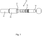
Fig. 1 is a perspective side elevation view of the tie rod of the present invention. -
Fig. 2 is a side elevational cross-sectional view of the tie rod. -
Fig. 3 is a side elevational cross-sectional view of one of the rod components of the tie rod. -
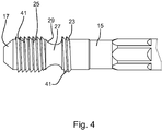
Fig. 4 is a partial side elevational view of one end of the rod element of the tie rod of the present invention. -
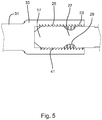
Fig. 5 is a partial side elevational cross sectional view. - The tie rod of the present invention is to be used with a vehicle. The tie rod is used to control the steered wheels of the vehicle. More particularly, the tie rod is designed to accommodate overload conditions that act in tension on the tie rod. The tie rod is designed to provide an indication that a tension overload has been encountered by the tie rod that compromises the proper function of the tie rod. The tie rod is also designed to elongate under tension overload conditions to protect the function of other components of the steering system. Other features and advantages of the invention will be more readily understood by referring to the drawings in connection with the following description.
- Tie rods of the prior art have a link section. The link section has a threaded section for connection to further link sections on one end and a ball joint on the other end that is connected to the suspension of the vehicle. Such tie rods of the prior art do not have an overload function other than the simple buckling of the link in the event of compression overload in a direction towards the center of the vehicle. In such tie rods, the compression overload condition causes a bend or curve in the tie rod that may or may not significantly impact the functionality of the tie rod. In addition, there is no damage indicator if the overload forces are placed on the tie rod in the other direction, a tension overload, which is away from the center of the vehicle. In the application of a tension overload there is usually a complete failure of the tie rod before there is any indication of damage to the tie rod due to an overload.
- The tie rod of the present invention, which is shown in the attached figures, has been designed to provide a progressive indication that the tie rod has been subjected to an overload sufficient to cause damage to the tie rod. When the overload reaches a predetermined magnitude, the overload protection feature will allow the tie rod to elongate to an extent that will significantly impact the handling of the vehicle and give the operator of the vehicle a clear warning that the tie rod and the suspension of the vehicle need to be checked and repaired. The yield of the material of the tie rod due to the overload condition results in a permanent change in the steering characteristics of the vehicle. The
tie rod 10 of the present invention has arod 15 having afirst end 17 and asecond end 19. A first plurality ofthreads 23 are positioned on thefirst end 17 of therod 15. A reduceddiameter section 27 is on thefirst end 17 of therod 15 adjacent the first plurality of threads. Therod 15 is cylindrical with a generally circular cross sectional shape. The reduceddiameter section 27 is agroove 29 that is formed in therod 15. The groove usually has a semicircular shape and the width of the groove extends in a direction towards the longitudinal axis of therod 15. The groove can also have a parabolic, elliptical or similar shape. Thegroove 29 has a depth that is from about 20 % to about 40 % of the diameter of therod 15. The groove has a width that is from about 1 diameter to about 3 diameters of the rod. - A
link 31, having achamber 33 positioned on one end, forms another part of the tie rod. Thechamber 33 has a plurality ofthreads 37 positioned on the interior of thechamber 33. Thelink 31 and thechamber 33 are generally cylindrical and have a substantially circular cross sectional shape. The plurality ofthreads 37 are disposed for engaging the first plurality ofthreads 23, that are positioned on the first end of therod 15. The first plurality ofthreads 23 positioned on therod 15 are designed to slip and deform when subjected to tension loads that exceed the design limits of the tie rod. The tension load that exceed the design limits, is a load that will cause therod 15 to move in a direction away from thelink 31. If sufficient tension load is placed on thetie rod 10, the reduceddiameter section 27 is also designed to elongate. The elongation of the reduced diameter section happens as the first plurality ofthreads 23 have been subjected to the tension load that causes the first plurality of threads to slip and deform. The first plurality ofthreads 23 and the reduceddiameter section 27 allow thetie rod 10 to deform and elongate, and to absorb loads or energy in tension over a longer distance. This results in the tie rod having the ability to progressively handle tension overloads and to modify the length of the tie rod progressively to provide a warning to the operator of the vehicle that an overload has occurred. - The
first end 17 of therod 15 that is positioned in thechamber 33 is designed to be secured to thelink 31. To assist in this connection between thelink 31 and the rod 15 a second plurality ofthreads 25 are positioned on therod 15 on the opposite side of the reduceddiameter section 27 from the first plurality ofthreads 23. The second plurality ofthreads 25 are disposed on the end ofrod 15 that extends the farthest into thechamber 33. The second plurality of threads threadingly engage the plurality ofthreads 37 in the chamber. A locking means, such as a glue, formed indentation or other means is used to keep therod 15 from disengaging from thechamber 33. It should be recognized, however, that other securing means, other than the second plurality of threads, can be utilized to secure therod 15 to thelink 31. As an example, a bore can be positioned to extend through thechamber 33 and thefirst end 17 of therod 15. A pin could be positioned in the bore that extends through the chamber and the rod to secure the rod to thelink 31. - The first and second pluralities of threads that are positioned on the
first end 17 of therod 15 are buttress threads. A buttress thread has aload resisting flank 41 that can accommodate compression loads that act against the flank that are much higher than loads that act against the buttress threads in the opposite direction. Such threads can accommodate large loads in one direction, but have a reduced capacity to handle loads in the opposite direction. In practice, the load that act against theflank 41 can be from about 1¼ to about 1¾ times larger than the forces that act on the threads in the opposite direction. In the present invention the load resisting flank is disposed toward thelink 31 so that compression loads in a direction along therod 15 towards thelink 31 will be placed against the load resisting flank. This results in the first and second pluralities of threads being able to accommodate compression loads that are much greater than the tension loads or loads that are directed in the opposite direction. The number of threads in the first and second plurality of threads and the thrust angle of theflank 41 can be adjusted to change the overload parameters of the tie rod. The first plurality ofthreads 23 will generally have a length less than 1 diameter of therod 15 in threads and the second plurality of threads will have greater than 1.5 diameter of therod 15 in threads. The thrust angle of theflank 41 is usually from about 30° to about 60° with respect to the longitudinal axis of therod 15. The size of the reduced diameter section and the configuration of the first and second plurality of threads can be adjusted to change the elongation parameters of therod 15 in response to overloads in tension. This allows the tie rod to be adjusted for different vehicles or driving conditions. - In most uses, the first plurality of
threads 23 are caused to slip and deform by the tension overload placed on the tie rod. Once the first plurality of threads have elongated thereduced diameter section 27 will elongate if the overload is sufficiently large. The progressive elongation results in a progressive compromise of the steering quality of the vehicle that give the operator of the vehicle an increasing indicator that the tie rod has been subjected to an overload that has compromised the effectiveness of the tie rod and the steering system. The deformation and elongation of thetie rod 15 absorbs energy and protects other components of the steering and suspension systems of the vehicle. - The above detailed description of the present invention is given for explanatory purposes. It will be apparent to those skilled in the art that numerous changes and modifications can be made without departing from the scope of the invention. Accordingly, the whole of the foregoing description is to be construed in an illustrative and not a limitative sense, the scope of the invention being defined solely by the appended claims.
Claims (14)
- A tie rod (10) to transmit steering motion to the wheels of a vehicle comprising:a rod (15) having a first end (17) and a second end (19);a first plurality of threads (23) positioned on the first end (17);a reduced diameter section (27) positioned on the first end (17) of the rod adjacent the first plurality of threads (23);a link (31) having a chamber (33) disposed on one end, the chamber (33) having a plurality of threads (37) that are disposed for engaging the first plurality of threads (23) on the first end (17) of the rod (15),characterized in thatthe first plurality of threads (23) being designed to slip and deform when subjected to tension loads that exceed the design limits of the tie rod (10).
- The tie rod of claim 1 wherein the reduced diameter section (27) is designed to elongate when subjected to tension loads that have caused the first plurality of threads (23) to elongate.
- The tie rod of claim 1 wherein the first plurality of threads (23) are buttress threads having a load resisting flank (41), the load resisting flank (41) disposed towards the link (31) wherein the first plurality of threads (23) can accommodate compression loads that are greater than the tension loads that can be accommodated by the first plurality of threads (23).
- The tie rod of claim 1 wherein the rod (15) and link (31) have a cylindrical shape with a circular cross section.
- The tie rod of claim 1 wherein a second plurality of threads (25) is positioned on the first end (17) of the rod (15) adjacent the side of the reduced diameter section (27) that is opposite to the first plurality of threads (23).
- The tie rod of claim 4 wherein the reduced diameter section (27) is a groove (29) that extends around the outer perimeter of the rod (15).
- The tie rod of claim 6 wherein the groove (29) has a depth from about 20% to about 40% of the diameter of the rod (15).
- The tie rod of claim 7 wherein the groove (29) has a semi-circular, parabolic or elliptical shape.
- The tie rod of claim 3 wherein the second plurality of threads (25) are buttress threads that have a load resisting flank (41) disposed towards the link (31), the second plurality of threads (25) being disposed to engage the plurality of threads (37) in the chamber.
- The tie rod of claim 9 wherein the first and second plurality of threads (23, 25) are the same size and configuration.
- The tie rod of claim 3 wherein the first plurality of threads (23) contains less than 1 diameter of the rod (15) in length of threads.
- The tie rod of claim 9 wherein the second plurality of threads (25) contains greater than 1.5 diameter of the rod (15) in length of threads.
- The tie rod of claim 3 wherein the load resisting flank (41) has a thrust angle from about 30° to about 60° with longitudinal axis of the rod (15).
- The tie rod of claim 9 wherein the load resisting flank (41) has a thrust angle from about 30° to about 60° with the longitudinal axis of the rod (15)
Applications Claiming Priority (2)
| Application Number | Priority Date | Filing Date | Title |
|---|---|---|---|
| US201462027478P | 2014-07-22 | 2014-07-22 | |
| PCT/US2015/041318 WO2016014521A1 (en) | 2014-07-22 | 2015-07-21 | Tie rod |
Publications (3)
| Publication Number | Publication Date |
|---|---|
| EP3172116A1 EP3172116A1 (en) | 2017-05-31 |
| EP3172116A4 EP3172116A4 (en) | 2018-04-04 |
| EP3172116B1 true EP3172116B1 (en) | 2019-06-26 |
Family
ID=55163629
Family Applications (1)
| Application Number | Title | Priority Date | Filing Date |
|---|---|---|---|
| EP15825136.3A Not-in-force EP3172116B1 (en) | 2014-07-22 | 2015-07-21 | Tie rod |
Country Status (3)
| Country | Link |
|---|---|
| EP (1) | EP3172116B1 (en) |
| CN (1) | CN106536330B (en) |
| WO (1) | WO2016014521A1 (en) |
Families Citing this family (2)
| Publication number | Priority date | Publication date | Assignee | Title |
|---|---|---|---|---|
| CN113662645A (en) * | 2020-04-30 | 2021-11-19 | 上海微创投资控股有限公司 | Growing rod |
| CN113104110B (en) * | 2021-05-24 | 2022-11-25 | 德惠市北方汽车底盘零部件有限公司 | Bent pull rod, manufacturing method thereof and automobile chassis |
Family Cites Families (7)
| Publication number | Priority date | Publication date | Assignee | Title |
|---|---|---|---|---|
| US4338054A (en) * | 1979-11-19 | 1982-07-06 | Dahl Norman C | Solid externally threaded fasteners having greatly increased ductility |
| US4890949A (en) * | 1988-04-07 | 1990-01-02 | Trw Inc. | Tie rod end |
| US5537814A (en) * | 1994-09-28 | 1996-07-23 | General Electric Company | High pressure gas generator rotor tie rod system for gas turbine engine |
| US5529316A (en) * | 1995-02-16 | 1996-06-25 | American Axle & Manufacturing, Inc. | Adjustable tie rod assembly |
| FR2996199B1 (en) * | 2012-10-01 | 2015-05-15 | Jtekt Europe Sas | STEERING LINK WITH FLANGED REINFORCEMENT SLEEVE |
| CN103043098A (en) * | 2012-12-29 | 2013-04-17 | 诸城市义和车桥有限公司 | Novel intermediate drag rod assembly |
| CN103253302A (en) * | 2013-02-21 | 2013-08-21 | 浙江吉利汽车研究院有限公司杭州分公司 | Automobile steering tie rod |
-
2015
- 2015-07-21 EP EP15825136.3A patent/EP3172116B1/en not_active Not-in-force
- 2015-07-21 CN CN201580039841.6A patent/CN106536330B/en not_active Expired - Fee Related
- 2015-07-21 WO PCT/US2015/041318 patent/WO2016014521A1/en not_active Ceased
Non-Patent Citations (1)
| Title |
|---|
| None * |
Also Published As
| Publication number | Publication date |
|---|---|
| CN106536330A (en) | 2017-03-22 |
| WO2016014521A1 (en) | 2016-01-28 |
| EP3172116A4 (en) | 2018-04-04 |
| CN106536330B (en) | 2019-09-24 |
| EP3172116A1 (en) | 2017-05-31 |
Similar Documents
| Publication | Publication Date | Title |
|---|---|---|
| US8210606B2 (en) | Energy absorption device for automobile seat, and assembly and set including said device | |
| EP2830914B1 (en) | Pedestrian protecting device for a vehicle | |
| US20150274192A1 (en) | Steering apparatus | |
| EP2399765B1 (en) | Motor vehicle suspension arm | |
| US10040477B2 (en) | Tie rod | |
| DE102014213364B4 (en) | Wheel carrier of a vehicle with a press fit connection | |
| US20160332496A1 (en) | Fusible linking yoke between the suspension arm and the engine cradle | |
| US20160031278A1 (en) | Axle link for a motor vehicle | |
| US20200140010A1 (en) | Force-Rated Tie Rod Assembly | |
| WO2016014521A1 (en) | Tie rod | |
| JPH0299470A (en) | Automobile steering gear | |
| US20130298374A1 (en) | Tie rod end removal tool | |
| EP2816244B1 (en) | Anti-theft locking device for vehicle wheels | |
| EP2817524A1 (en) | Separation fastener assembly | |
| JP6185810B2 (en) | Shock absorption structure | |
| WO2018201052A1 (en) | Frangible fastener system | |
| EP2754902A2 (en) | Threaded fastening system | |
| US20210131463A1 (en) | Strapping device | |
| KR20110089391A (en) | Loosening Floating Nut | |
| EP2937579A1 (en) | Compression rod having a buckling initiating feature | |
| DE102014104782B4 (en) | Energy absorbing element for a bumper of a motor vehicle and bumper for a motor vehicle | |
| DE102015224750A1 (en) | vehicle | |
| WO2014077740A1 (en) | Active bolt release arrangement | |
| KR101582855B1 (en) | Active Roll Stabilizer | |
| KR20120030852A (en) | Lower control arm of suspension system for vehicle |
Legal Events
| Date | Code | Title | Description |
|---|---|---|---|
| STAA | Information on the status of an ep patent application or granted ep patent |
Free format text: STATUS: THE INTERNATIONAL PUBLICATION HAS BEEN MADE |
|
| PUAI | Public reference made under article 153(3) epc to a published international application that has entered the european phase |
Free format text: ORIGINAL CODE: 0009012 |
|
| STAA | Information on the status of an ep patent application or granted ep patent |
Free format text: STATUS: REQUEST FOR EXAMINATION WAS MADE |
|
| 17P | Request for examination filed |
Effective date: 20170102 |
|
| AK | Designated contracting states |
Kind code of ref document: A1 Designated state(s): AL AT BE BG CH CY CZ DE DK EE ES FI FR GB GR HR HU IE IS IT LI LT LU LV MC MK MT NL NO PL PT RO RS SE SI SK SM TR |
|
| AX | Request for extension of the european patent |
Extension state: BA ME |
|
| DAV | Request for validation of the european patent (deleted) | ||
| DAX | Request for extension of the european patent (deleted) | ||
| A4 | Supplementary search report drawn up and despatched |
Effective date: 20180302 |
|
| RIC1 | Information provided on ipc code assigned before grant |
Ipc: B62D 7/20 20060101AFI20180226BHEP |
|
| GRAP | Despatch of communication of intention to grant a patent |
Free format text: ORIGINAL CODE: EPIDOSNIGR1 |
|
| STAA | Information on the status of an ep patent application or granted ep patent |
Free format text: STATUS: GRANT OF PATENT IS INTENDED |
|
| INTG | Intention to grant announced |
Effective date: 20180704 |
|
| GRAS | Grant fee paid |
Free format text: ORIGINAL CODE: EPIDOSNIGR3 |
|
| GRAA | (expected) grant |
Free format text: ORIGINAL CODE: 0009210 |
|
| STAA | Information on the status of an ep patent application or granted ep patent |
Free format text: STATUS: THE PATENT HAS BEEN GRANTED |
|
| AK | Designated contracting states |
Kind code of ref document: B1 Designated state(s): AL AT BE BG CH CY CZ DE DK EE ES FI FR GB GR HR HU IE IS IT LI LT LU LV MC MK MT NL NO PL PT RO RS SE SI SK SM TR |
|
| REG | Reference to a national code |
Ref country code: GB Ref legal event code: FG4D |
|
| REG | Reference to a national code |
Ref country code: CH Ref legal event code: EP |
|
| REG | Reference to a national code |
Ref country code: AT Ref legal event code: REF Ref document number: 1147952 Country of ref document: AT Kind code of ref document: T Effective date: 20190715 |
|
| REG | Reference to a national code |
Ref country code: DE Ref legal event code: R096 Ref document number: 602015032846 Country of ref document: DE |
|
| REG | Reference to a national code |
Ref country code: IE Ref legal event code: FG4D |
|
| REG | Reference to a national code |
Ref country code: NL Ref legal event code: MP Effective date: 20190626 |
|
| PG25 | Lapsed in a contracting state [announced via postgrant information from national office to epo] |
Ref country code: FI Free format text: LAPSE BECAUSE OF FAILURE TO SUBMIT A TRANSLATION OF THE DESCRIPTION OR TO PAY THE FEE WITHIN THE PRESCRIBED TIME-LIMIT Effective date: 20190626 Ref country code: LT Free format text: LAPSE BECAUSE OF FAILURE TO SUBMIT A TRANSLATION OF THE DESCRIPTION OR TO PAY THE FEE WITHIN THE PRESCRIBED TIME-LIMIT Effective date: 20190626 Ref country code: HR Free format text: LAPSE BECAUSE OF FAILURE TO SUBMIT A TRANSLATION OF THE DESCRIPTION OR TO PAY THE FEE WITHIN THE PRESCRIBED TIME-LIMIT Effective date: 20190626 Ref country code: SE Free format text: LAPSE BECAUSE OF FAILURE TO SUBMIT A TRANSLATION OF THE DESCRIPTION OR TO PAY THE FEE WITHIN THE PRESCRIBED TIME-LIMIT Effective date: 20190626 Ref country code: NO Free format text: LAPSE BECAUSE OF FAILURE TO SUBMIT A TRANSLATION OF THE DESCRIPTION OR TO PAY THE FEE WITHIN THE PRESCRIBED TIME-LIMIT Effective date: 20190926 Ref country code: AL Free format text: LAPSE BECAUSE OF FAILURE TO SUBMIT A TRANSLATION OF THE DESCRIPTION OR TO PAY THE FEE WITHIN THE PRESCRIBED TIME-LIMIT Effective date: 20190626 |
|
| REG | Reference to a national code |
Ref country code: LT Ref legal event code: MG4D |
|
| PG25 | Lapsed in a contracting state [announced via postgrant information from national office to epo] |
Ref country code: BG Free format text: LAPSE BECAUSE OF FAILURE TO SUBMIT A TRANSLATION OF THE DESCRIPTION OR TO PAY THE FEE WITHIN THE PRESCRIBED TIME-LIMIT Effective date: 20190926 Ref country code: RS Free format text: LAPSE BECAUSE OF FAILURE TO SUBMIT A TRANSLATION OF THE DESCRIPTION OR TO PAY THE FEE WITHIN THE PRESCRIBED TIME-LIMIT Effective date: 20190626 Ref country code: LV Free format text: LAPSE BECAUSE OF FAILURE TO SUBMIT A TRANSLATION OF THE DESCRIPTION OR TO PAY THE FEE WITHIN THE PRESCRIBED TIME-LIMIT Effective date: 20190626 Ref country code: GR Free format text: LAPSE BECAUSE OF FAILURE TO SUBMIT A TRANSLATION OF THE DESCRIPTION OR TO PAY THE FEE WITHIN THE PRESCRIBED TIME-LIMIT Effective date: 20190927 |
|
| REG | Reference to a national code |
Ref country code: AT Ref legal event code: MK05 Ref document number: 1147952 Country of ref document: AT Kind code of ref document: T Effective date: 20190626 |
|
| PG25 | Lapsed in a contracting state [announced via postgrant information from national office to epo] |
Ref country code: SK Free format text: LAPSE BECAUSE OF FAILURE TO SUBMIT A TRANSLATION OF THE DESCRIPTION OR TO PAY THE FEE WITHIN THE PRESCRIBED TIME-LIMIT Effective date: 20190626 Ref country code: RO Free format text: LAPSE BECAUSE OF FAILURE TO SUBMIT A TRANSLATION OF THE DESCRIPTION OR TO PAY THE FEE WITHIN THE PRESCRIBED TIME-LIMIT Effective date: 20190626 Ref country code: EE Free format text: LAPSE BECAUSE OF FAILURE TO SUBMIT A TRANSLATION OF THE DESCRIPTION OR TO PAY THE FEE WITHIN THE PRESCRIBED TIME-LIMIT Effective date: 20190626 Ref country code: PT Free format text: LAPSE BECAUSE OF FAILURE TO SUBMIT A TRANSLATION OF THE DESCRIPTION OR TO PAY THE FEE WITHIN THE PRESCRIBED TIME-LIMIT Effective date: 20191028 Ref country code: AT Free format text: LAPSE BECAUSE OF FAILURE TO SUBMIT A TRANSLATION OF THE DESCRIPTION OR TO PAY THE FEE WITHIN THE PRESCRIBED TIME-LIMIT Effective date: 20190626 Ref country code: CZ Free format text: LAPSE BECAUSE OF FAILURE TO SUBMIT A TRANSLATION OF THE DESCRIPTION OR TO PAY THE FEE WITHIN THE PRESCRIBED TIME-LIMIT Effective date: 20190626 Ref country code: NL Free format text: LAPSE BECAUSE OF FAILURE TO SUBMIT A TRANSLATION OF THE DESCRIPTION OR TO PAY THE FEE WITHIN THE PRESCRIBED TIME-LIMIT Effective date: 20190626 |
|
| PG25 | Lapsed in a contracting state [announced via postgrant information from national office to epo] |
Ref country code: SM Free format text: LAPSE BECAUSE OF FAILURE TO SUBMIT A TRANSLATION OF THE DESCRIPTION OR TO PAY THE FEE WITHIN THE PRESCRIBED TIME-LIMIT Effective date: 20190626 Ref country code: IT Free format text: LAPSE BECAUSE OF FAILURE TO SUBMIT A TRANSLATION OF THE DESCRIPTION OR TO PAY THE FEE WITHIN THE PRESCRIBED TIME-LIMIT Effective date: 20190626 Ref country code: ES Free format text: LAPSE BECAUSE OF FAILURE TO SUBMIT A TRANSLATION OF THE DESCRIPTION OR TO PAY THE FEE WITHIN THE PRESCRIBED TIME-LIMIT Effective date: 20190626 Ref country code: IS Free format text: LAPSE BECAUSE OF FAILURE TO SUBMIT A TRANSLATION OF THE DESCRIPTION OR TO PAY THE FEE WITHIN THE PRESCRIBED TIME-LIMIT Effective date: 20191026 |
|
| REG | Reference to a national code |
Ref country code: CH Ref legal event code: PL |
|
| PG25 | Lapsed in a contracting state [announced via postgrant information from national office to epo] |
Ref country code: TR Free format text: LAPSE BECAUSE OF FAILURE TO SUBMIT A TRANSLATION OF THE DESCRIPTION OR TO PAY THE FEE WITHIN THE PRESCRIBED TIME-LIMIT Effective date: 20190626 Ref country code: MC Free format text: LAPSE BECAUSE OF FAILURE TO SUBMIT A TRANSLATION OF THE DESCRIPTION OR TO PAY THE FEE WITHIN THE PRESCRIBED TIME-LIMIT Effective date: 20190626 |
|
| REG | Reference to a national code |
Ref country code: BE Ref legal event code: MM Effective date: 20190731 |
|
| PG25 | Lapsed in a contracting state [announced via postgrant information from national office to epo] |
Ref country code: PL Free format text: LAPSE BECAUSE OF FAILURE TO SUBMIT A TRANSLATION OF THE DESCRIPTION OR TO PAY THE FEE WITHIN THE PRESCRIBED TIME-LIMIT Effective date: 20190626 Ref country code: DK Free format text: LAPSE BECAUSE OF FAILURE TO SUBMIT A TRANSLATION OF THE DESCRIPTION OR TO PAY THE FEE WITHIN THE PRESCRIBED TIME-LIMIT Effective date: 20190626 |
|
| PG25 | Lapsed in a contracting state [announced via postgrant information from national office to epo] |
Ref country code: IS Free format text: LAPSE BECAUSE OF FAILURE TO SUBMIT A TRANSLATION OF THE DESCRIPTION OR TO PAY THE FEE WITHIN THE PRESCRIBED TIME-LIMIT Effective date: 20200224 Ref country code: BE Free format text: LAPSE BECAUSE OF NON-PAYMENT OF DUE FEES Effective date: 20190731 Ref country code: LU Free format text: LAPSE BECAUSE OF NON-PAYMENT OF DUE FEES Effective date: 20190721 Ref country code: CH Free format text: LAPSE BECAUSE OF NON-PAYMENT OF DUE FEES Effective date: 20190731 Ref country code: LI Free format text: LAPSE BECAUSE OF NON-PAYMENT OF DUE FEES Effective date: 20190731 |
|
| REG | Reference to a national code |
Ref country code: DE Ref legal event code: R097 Ref document number: 602015032846 Country of ref document: DE |
|
| PLBE | No opposition filed within time limit |
Free format text: ORIGINAL CODE: 0009261 |
|
| STAA | Information on the status of an ep patent application or granted ep patent |
Free format text: STATUS: NO OPPOSITION FILED WITHIN TIME LIMIT |
|
| PG2D | Information on lapse in contracting state deleted |
Ref country code: IS |
|
| PG25 | Lapsed in a contracting state [announced via postgrant information from national office to epo] |
Ref country code: IE Free format text: LAPSE BECAUSE OF NON-PAYMENT OF DUE FEES Effective date: 20190721 |
|
| 26N | No opposition filed |
Effective date: 20200603 |
|
| PG25 | Lapsed in a contracting state [announced via postgrant information from national office to epo] |
Ref country code: SI Free format text: LAPSE BECAUSE OF FAILURE TO SUBMIT A TRANSLATION OF THE DESCRIPTION OR TO PAY THE FEE WITHIN THE PRESCRIBED TIME-LIMIT Effective date: 20190626 |
|
| PG25 | Lapsed in a contracting state [announced via postgrant information from national office to epo] |
Ref country code: CY Free format text: LAPSE BECAUSE OF FAILURE TO SUBMIT A TRANSLATION OF THE DESCRIPTION OR TO PAY THE FEE WITHIN THE PRESCRIBED TIME-LIMIT Effective date: 20190626 |
|
| PG25 | Lapsed in a contracting state [announced via postgrant information from national office to epo] |
Ref country code: MT Free format text: LAPSE BECAUSE OF FAILURE TO SUBMIT A TRANSLATION OF THE DESCRIPTION OR TO PAY THE FEE WITHIN THE PRESCRIBED TIME-LIMIT Effective date: 20190626 Ref country code: HU Free format text: LAPSE BECAUSE OF FAILURE TO SUBMIT A TRANSLATION OF THE DESCRIPTION OR TO PAY THE FEE WITHIN THE PRESCRIBED TIME-LIMIT; INVALID AB INITIO Effective date: 20150721 |
|
| PGFP | Annual fee paid to national office [announced via postgrant information from national office to epo] |
Ref country code: FR Payment date: 20210722 Year of fee payment: 7 |
|
| PGFP | Annual fee paid to national office [announced via postgrant information from national office to epo] |
Ref country code: GB Payment date: 20210722 Year of fee payment: 7 Ref country code: DE Payment date: 20210924 Year of fee payment: 7 |
|
| PG25 | Lapsed in a contracting state [announced via postgrant information from national office to epo] |
Ref country code: MK Free format text: LAPSE BECAUSE OF FAILURE TO SUBMIT A TRANSLATION OF THE DESCRIPTION OR TO PAY THE FEE WITHIN THE PRESCRIBED TIME-LIMIT Effective date: 20190626 |
|
| REG | Reference to a national code |
Ref country code: DE Ref legal event code: R119 Ref document number: 602015032846 Country of ref document: DE |
|
| GBPC | Gb: european patent ceased through non-payment of renewal fee |
Effective date: 20220721 |
|
| PG25 | Lapsed in a contracting state [announced via postgrant information from national office to epo] |
Ref country code: FR Free format text: LAPSE BECAUSE OF NON-PAYMENT OF DUE FEES Effective date: 20220731 |
|
| PG25 | Lapsed in a contracting state [announced via postgrant information from national office to epo] |
Ref country code: GB Free format text: LAPSE BECAUSE OF NON-PAYMENT OF DUE FEES Effective date: 20220721 Ref country code: DE Free format text: LAPSE BECAUSE OF NON-PAYMENT OF DUE FEES Effective date: 20230201 |