EP3172064B1 - Reifen - Google Patents
Reifen Download PDFInfo
- Publication number
- EP3172064B1 EP3172064B1 EP15723209.1A EP15723209A EP3172064B1 EP 3172064 B1 EP3172064 B1 EP 3172064B1 EP 15723209 A EP15723209 A EP 15723209A EP 3172064 B1 EP3172064 B1 EP 3172064B1
- Authority
- EP
- European Patent Office
- Prior art keywords
- tyre
- signal
- tire
- generating element
- adapter
- Prior art date
- Legal status (The legal status is an assumption and is not a legal conclusion. Google has not performed a legal analysis and makes no representation as to the accuracy of the status listed.)
- Active
Links
Images


Classifications
-
- B—PERFORMING OPERATIONS; TRANSPORTING
- B62—LAND VEHICLES FOR TRAVELLING OTHERWISE THAN ON RAILS
- B62J—CYCLE SADDLES OR SEATS; AUXILIARY DEVICES OR ACCESSORIES SPECIALLY ADAPTED TO CYCLES AND NOT OTHERWISE PROVIDED FOR, e.g. ARTICLE CARRIERS OR CYCLE PROTECTORS
- B62J45/00—Electrical equipment arrangements specially adapted for use as accessories on cycles, not otherwise provided for
- B62J45/40—Sensor arrangements; Mounting thereof
- B62J45/42—Sensor arrangements; Mounting thereof characterised by mounting
- B62J45/423—Sensor arrangements; Mounting thereof characterised by mounting on or besides the wheel
-
- B—PERFORMING OPERATIONS; TRANSPORTING
- B60—VEHICLES IN GENERAL
- B60C—VEHICLE TYRES; TYRE INFLATION; TYRE CHANGING; CONNECTING VALVES TO INFLATABLE ELASTIC BODIES IN GENERAL; DEVICES OR ARRANGEMENTS RELATED TO TYRES
- B60C13/00—Tyre sidewalls; Protecting, decorating, marking, or the like, thereof
-
- B—PERFORMING OPERATIONS; TRANSPORTING
- B29—WORKING OF PLASTICS; WORKING OF SUBSTANCES IN A PLASTIC STATE IN GENERAL
- B29D—PRODUCING PARTICULAR ARTICLES FROM PLASTICS OR FROM SUBSTANCES IN A PLASTIC STATE
- B29D30/00—Producing pneumatic or solid tyres or parts thereof
- B29D30/0061—Accessories, details or auxiliary operations not otherwise provided for
-
- B—PERFORMING OPERATIONS; TRANSPORTING
- B60—VEHICLES IN GENERAL
- B60C—VEHICLE TYRES; TYRE INFLATION; TYRE CHANGING; CONNECTING VALVES TO INFLATABLE ELASTIC BODIES IN GENERAL; DEVICES OR ARRANGEMENTS RELATED TO TYRES
- B60C19/00—Tyre parts or constructions not otherwise provided for
-
- B—PERFORMING OPERATIONS; TRANSPORTING
- B62—LAND VEHICLES FOR TRAVELLING OTHERWISE THAN ON RAILS
- B62J—CYCLE SADDLES OR SEATS; AUXILIARY DEVICES OR ACCESSORIES SPECIALLY ADAPTED TO CYCLES AND NOT OTHERWISE PROVIDED FOR, e.g. ARTICLE CARRIERS OR CYCLE PROTECTORS
- B62J45/00—Electrical equipment arrangements specially adapted for use as accessories on cycles, not otherwise provided for
- B62J45/40—Sensor arrangements; Mounting thereof
- B62J45/41—Sensor arrangements; Mounting thereof characterised by the type of sensor
- B62J45/412—Speed sensors
-
- B—PERFORMING OPERATIONS; TRANSPORTING
- B62—LAND VEHICLES FOR TRAVELLING OTHERWISE THAN ON RAILS
- B62M—RIDER PROPULSION OF WHEELED VEHICLES OR SLEDGES; POWERED PROPULSION OF SLEDGES OR SINGLE-TRACK CYCLES; TRANSMISSIONS SPECIALLY ADAPTED FOR SUCH VEHICLES
- B62M7/00—Motorcycles characterised by position of motor or engine
- B62M7/12—Motorcycles characterised by position of motor or engine with the engine beside or within the driven wheel
-
- G—PHYSICS
- G01—MEASURING; TESTING
- G01P—MEASURING LINEAR OR ANGULAR SPEED, ACCELERATION, DECELERATION, OR SHOCK; INDICATING PRESENCE, ABSENCE, OR DIRECTION, OF MOVEMENT
- G01P3/00—Measuring linear or angular speed; Measuring differences of linear or angular speeds
- G01P3/42—Devices characterised by the use of electric or magnetic means
- G01P3/44—Devices characterised by the use of electric or magnetic means for measuring angular speed
- G01P3/48—Devices characterised by the use of electric or magnetic means for measuring angular speed by measuring frequency of generated current or voltage
- G01P3/481—Devices characterised by the use of electric or magnetic means for measuring angular speed by measuring frequency of generated current or voltage of pulse signals
- G01P3/487—Devices characterised by the use of electric or magnetic means for measuring angular speed by measuring frequency of generated current or voltage of pulse signals delivered by rotating magnets
-
- B—PERFORMING OPERATIONS; TRANSPORTING
- B29—WORKING OF PLASTICS; WORKING OF SUBSTANCES IN A PLASTIC STATE IN GENERAL
- B29D—PRODUCING PARTICULAR ARTICLES FROM PLASTICS OR FROM SUBSTANCES IN A PLASTIC STATE
- B29D30/00—Producing pneumatic or solid tyres or parts thereof
- B29D30/0061—Accessories, details or auxiliary operations not otherwise provided for
- B29D2030/0077—Directly attaching monitoring devices to tyres before or after vulcanization, e.g. microchips
-
- B—PERFORMING OPERATIONS; TRANSPORTING
- B60—VEHICLES IN GENERAL
- B60C—VEHICLE TYRES; TYRE INFLATION; TYRE CHANGING; CONNECTING VALVES TO INFLATABLE ELASTIC BODIES IN GENERAL; DEVICES OR ARRANGEMENTS RELATED TO TYRES
- B60C11/00—Tyre tread bands; Tread patterns; Anti-skid inserts
- B60C11/14—Anti-skid inserts, e.g. vulcanised into the tread band
-
- B—PERFORMING OPERATIONS; TRANSPORTING
- B60—VEHICLES IN GENERAL
- B60C—VEHICLE TYRES; TYRE INFLATION; TYRE CHANGING; CONNECTING VALVES TO INFLATABLE ELASTIC BODIES IN GENERAL; DEVICES OR ARRANGEMENTS RELATED TO TYRES
- B60C19/00—Tyre parts or constructions not otherwise provided for
- B60C2019/004—Tyre sensors other than for detecting tyre pressure
-
- B—PERFORMING OPERATIONS; TRANSPORTING
- B60—VEHICLES IN GENERAL
- B60C—VEHICLE TYRES; TYRE INFLATION; TYRE CHANGING; CONNECTING VALVES TO INFLATABLE ELASTIC BODIES IN GENERAL; DEVICES OR ARRANGEMENTS RELATED TO TYRES
- B60C19/00—Tyre parts or constructions not otherwise provided for
- B60C2019/005—Magnets integrated within the tyre structure
-
- B—PERFORMING OPERATIONS; TRANSPORTING
- B60—VEHICLES IN GENERAL
- B60C—VEHICLE TYRES; TYRE INFLATION; TYRE CHANGING; CONNECTING VALVES TO INFLATABLE ELASTIC BODIES IN GENERAL; DEVICES OR ARRANGEMENTS RELATED TO TYRES
- B60C2200/00—Tyres specially adapted for particular applications
- B60C2200/12—Tyres specially adapted for particular applications for bicycles
Definitions
- the invention relates to a tire, in particular two-wheeled tire, with a device for generating rotation-dependent signals, wherein the device is arranged in the tire or connected to the tire and having a signal-generating element. Also disclosed are a method of making such a two-wheel tire and a system for generating signals for controlling a two-wheel drive.
- magnets are provided as sensors (signal generator) for sensors in such systems, which are designed as REED contact, HALL sensors or similar sensors.
- sensors signal generator
- the speedometer signal information e.g. the speedometer signal information and calculates therefrom speed, distance, average speed, partial distance, etc.
- the max. Km / h support for e-bikes at 32Km / h.
- the signal-generating magnet is attached to a spoke in the front and / or rear wheel.
- This magnet is visually very visible and changes the design negatively. Also, the magnet can twist, so that then no function is given.
- Such a spoke magnet can easily twist by carelessness or get lost and thus bring the speedometer and / or the entire e-bike drive system completely to a standstill. In racing bikes, the spoke magnet produces a noticeable increase in air resistance and thus an additional disadvantage.
- the WO 2004/057274 A1 discloses for this purpose a revolution counter for a bicycle in which a magnetic element is incorporated in the plane of symmetry of a wheel within the tire or a tube located in the tire.
- the magnetic element moves with each revolution of the wheel through the receiving area of a sensor attached to the bicycle frame and responsive to magnetic induction, so that the rotations can be counted.
- the magnetic element may be adhered to the inside of the tire or hose.
- this relatively strong magnets must be used to ensure sufficient permeability through the rubber layers of the tire or hose and to generate a signal at the sensor.
- the DE 3911627A1 discloses a lighting system for bicycles, in which permanent magnets are integrated in a wheel of the bicycle.
- these permanent magnets are mounted on the inside of the tread of a tire and cooperate with a generator attached to the frame of the bicycle.
- a generator attached to the frame of the bicycle.
- the heat required to vulcanize the tire (about 180 ° C for over 200 seconds) lowers the energy value of the magnets, as magnets lose their magnetic properties when heated. There are magnets that tolerate such temperatures, but these are too low by the energy values to ensure a safe function.
- the DE 10 2010 042808 A1 discloses another solution, namely a device for speed detection with a arranged on a valve of a hose magnetic piece whose trajectory passes through the measuring range of a sensor attached to the frame.
- the disadvantage here is that the valve sits centrally in the rim and thus is relatively far away from a z. B. trained as a REED contact sensor.
- the generic form reveals DE 60 2004 001 129 T2 a pneumatic tire with a support on at least a part of its surface, wherein the support consists of two layers.
- the first layer is the one in contact with the pneumatic tire and the second layer is an outwardly facing overlay or cover layer on the inner, first layer.
- the inner layer consists of a plastic foam, which has certain void contents, a certain thickness and a certain density. Affixed to the elastomeric material of a pneumatic tire are markings, chips or unspecified soft or hard objects.
- the WO 2015-041756 A1 discloses a method of securing an object, such as an electronic device, to a tire sidewall.
- the object is arranged on the side wall such that adjacent side wall parts project beyond the object. The object itself remains visible.
- the JP 2013107460 A discloses the design of the sidewall of a tire for receiving a sensor by means of projections and a lid or receiving body / adapter
- For the invention therefore had the task of providing a bicycle tire with a device for generating rotation-dependent signals, preferably for speedometer or for use in a control system for a motorized two-wheel drive that works as independent as possible from weather or air resistance, which is easy to manufacture or retrofit and and which interacts as effectively as possible with the required sensors on the bicycle frame.
- the signal-generating element is received in a form-fitting or non-positively connected with the tire body holding element, wherein the holding element is arranged substantially on the outside of strength members or reinforcing elements of the tire, in particular on the outside of the tire carcass in or on the side wall of the tire.
- the signal-generating element is received in the holding member so that the signal-generating element forms part of the outer surface of the tire or overhangs the outer surface of the tire.
- the signal-generating element is securely and immovably connected to a rotating part, can not be twisted and is well protected against the weather. If the signal-generating element according to the invention mounted on or in the tire, as well as the cable from, for example, as a REED contact trained sensor to the speedometer or the control unit significantly shortened, which is reflected not only in the cost, but also ensures shorter installation times. In addition, the distance from signal generating element to the sensor is reduced to the smallest possible degree.
- the holding element is designed as a signal-generating element at least partially surrounding bead or guard ring.
- This can be a shearing z. B. on curbs.
- the bead or guard ring as protection against shearing can be carried out as a negative mold in the Vukanisationsform. This shearing protection must be present while driving only towards the ground, or at the points of the outer tire wall where shearing is possible.
- the signal-generating element is accommodated in an adapter, in particular an adapter made of wear-resistant material, which in turn is accommodated in the holding element.
- an adapter in particular an adapter made of wear-resistant material, which in turn is accommodated in the holding element.
- the signal-generating element together with adapter can then form part of the outer surface of the tire or project beyond the outer surface of the tire.
- the signal-generating element is releasably connected to the adapter, in particular screwed to the adapter.
- This makes it possible to easily exchange worn signal-generating elements in the simplest way. Also, this is a simple replacement of a z. B. formed as a magnet signal generating element by a stronger magnet possible to bridge a larger path. This allows simpler and customized solutions.
- a further advantageous embodiment is that the material of the holding element corresponds to the tire material and is connected to the tire by vulcanization or gluing. This facilitates manufacturing and ensures safe and unsolvable Connection. Such a cohesive combination can be integrated into the usual production as well as handle particularly well in retrofitting.
- a further advantageous embodiment is that the holding element is designed as a profile part, tread lugs or side wall reinforcement of the tire.
- the signaling element and the holding element can be designed so that it hardly noticeable within the normal tire design / tire design.
- a further advantageous embodiment is that the holding element, possibly adapter and signal-generating element form a spike.
- Known spikes have a plate-shaped root with which the spike is anchored in the tire and having the largest diameter of the spike parts.
- the root is usually connected via a neck portion with a spike shell
- the spike top usually consists of a thicker spiked part and a contrast tapered spike tip, which usually protrudes from the surface / tread of the tire.
- All parts of the introduced into the tread body are cylindrical, so have two bases, which are parallel, even, congruent and connected by a lateral surface.
- the bases may in this case have different shapes, for example those of a circle, a triangle, a square, a rectangle or an oval.
- the signal-generating element is detachably connected to the adapter, in particular bolted to the adapter, you can also screw the spike from two parts.
- the spike head itself has a threaded hole in its shaft. This is used to screw in e.g. a magnet.
- the magnet is designed so that it can be screwed by means of a thread directly into the spike head. Shape and size can be changed depending on the application.
- Another advantageous due to its simplicity method for producing a two-wheeled tire according to the invention is that the trained especially in the form of a spike signal generating element, possibly with adapter, is injected by means of a gun in the already provided on the tire holder, as with conventional Spikes happen, which are arranged to increase the adhesion of ice and snow in the tread.
- the two-wheeled tire according to the invention can be used in a system for generating signals for controlling the drive of a two-wheeler, in which the bicycle has at least one two-wheeled tire according to the invention and in which on the frame of the bicycle, in particular on a fork, rear or swing arm, a sensor is arranged in the vicinity of the two-wheeled tire so that it detects the rotation-dependent signals of the arranged in the two-wheel tire signal generating element and provides the control as an input signal.
- tire according to the invention with its signal-generating element can also be readily used for vehicles other than two-wheeled vehicles.
- Fig. 1 shows a sketch of a two-wheeled tire 1 on a rim 10 in section, with a device 2 for generating rotation-dependent signals, in which the device 2 is connected to the tire side wall 9 by gluing.
- Fig. 2 shows a corresponding ZweiradMail 3 in section, in which a means 4 for generating rotation-dependent signals with the tire side wall 7 is connected by vulcanization.
- Fig. 3 shows, also in section and as a sketch, an enlarged view of the design. It can be seen first formed as a permanent magnet and recorded in an adapter 5 signal generating element 6, in which case the signal-generating element 6 together with the adapter 5 made of wear-resistant material in one with the Tire body or the tire sidewall 7 frictionally connected by vulcanization holding element 8 are added.
- the retaining element 8 like the retaining element 12, is arranged substantially on the outside of the tire carcass 11 in or on the side wall 7, 9 of the tire and the signal-generating element 6 is received in the retaining element so that the signal-generating element 6 projects beyond the outer surface of the tire.
- the material of the holding elements 8 and 12 corresponds to the side wall material, so it is made of rubber.
- the holding elements 8 and 12 are formed as side wall reinforcement.
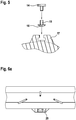
- Fig. 4 again shows a diagram of a further adapter 13, here without inserted magnets as a signal-generating element, designed for an embodiment in which the holding element, possibly adapter and signal-generating element form a spike.
- Fig. 5 shows a schematic diagram of an embodiment in which the signal-generating element 14 designed as a magnet is releasably, namely screwed, connected to the adapter 15.
- the signal-generating element 14 at one part of its circumference on an external thread, while the adapter 15 is provided with an internal thread and a thickened head 16 of the complementary recess of the holder 17 can be engaged.
- first adapter 15 and signal generation of the element 14 are screwed together. Thereafter, the thus screwed part is shot using a specially designed pistol in the recess 17 of the holder.
- the entire system is hinted at in the Fig. 1 and 2 recognizable.
- the system used on a two-wheeler not shown, has a two-wheeled tire according to the invention 1, 3 and arranged on a fork or rocker also not shown sensor 18, 19, the rotation-dependent signals of the Detected signal generating element and provides the control as an input signal available.
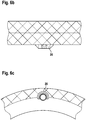
- Fig. 6a to 6c show the embodiment of the bicycle tire according to the invention, in which the holding element is designed as a signal generating element and the adapter partially surrounding bead or guard ring 20. This can be a shearing z. B. on curbs.
- FIG. 6C shows a side view of the two-wheel tire according to the invention, in which the bead 20 is arranged in the transition region between the tread and side wall.
- the bead is arranged so that it is always oriented towards the ground upon rotation of the bicycle tire, so that any bumping on curbs or edges of road bumps does not lead to damage to the signal-generating element.
- the FIG. 6B shows a view from above on the tread. Again, the protruding bead 20 is easy to see.
- the FIG. 6A shows a view of the wheel plane out, so seen from the wheel hub to the rim.
- This shearing protection is in this embodiment while driving only to the ground, so only at the points of the tire outer wall, where a shearing can occur at all.
Landscapes
- Engineering & Computer Science (AREA)
- Mechanical Engineering (AREA)
- Chemical & Material Sciences (AREA)
- Combustion & Propulsion (AREA)
- Physics & Mathematics (AREA)
- General Physics & Mathematics (AREA)
- Transportation (AREA)
- Tires In General (AREA)
Description
- Die Erfindung betrifft einen Reifen, insbesondere Zweiradreifen, mit einer Einrichtung zur Erzeugung von umdrehungsabhängigen Signalen, bei der die Einrichtung im Reifen angeordnet oder mit dem Reifen verbunden ist und ein signalerzeugendes Element aufweist. Ebenfalls sind ein Verfahren zur Herstellung eines solchen Zweiradreifens und ein System zur Erzeugung von Signalen für die Steuerung eines Zweiradantriebs offenbart.
- Üblicherweise benötigen elektrische Antriebe für Zweiräder, beispielsweise E-Bike Motoren, ebenso wie elektronische Fahrradtachometer, Sensoren zur Detektion der Rad- oder Pedalumdrehungen, um daraus u. a. die Geschwindigkeit zu ermitteln. Hierzu gehören natürlich Einrichtungen zur Signalerzeugung für solche Sensoren.
- Üblicherweise sind in solchen Systemen Magneten als Impulsgeber (Signalerzeuger) für Sensoren vorgesehen, die als REED-Kontakt, HALL-Sensoren oder ähnliche Sensoren ausgebildet sind. Bei jedem Vorbeilaufen des Magnetes an dem Sensor bekommt z.B. das Tachometer eine Signalinformation und errechnet hieraus Geschwindigkeit, Wegstrecke, Durchschnittsgeschwindigkeit, Teilstrecke etc. Beim E-Bike mit Mittelmotor wird hier z.B. in Europa mit solchen Systemen bei bis zu 25Km/h liegende Motorunterstützung abgeregelt. In den USA liegt der Wert der max. Km/h Unterstützung bei E-Bikes bei 32Km/h.
- Üblicherweise wird der signalerzeugende Magnet an einer Speiche im Vorder- und/oder Hinterrad angebracht. Dieser Magnet ist optisch sehr gut sichtbar und verändert das Design negativ. Ebenfalls kann sich der Magnet verdrehen, so dass dann keine Funktion mehr gegeben ist. Ein solcher Speichen-Magnet kann sich durch Unachtsamkeit leicht verdrehen oder verloren gehen und somit den Tacho und/oder auch das gesamte E-Bike Antriebssystem komplett zum Erliegen bringen. Bei Rennrädern erzeugt der Speichen-Magnet eine merkbare Erhöhung des Luftwiderstands und damit einen zusätzlichen Nachteil.
- Zur Lösung des Problems wurde bereits überlegt, den Magnet im Gummi der Lauffläche oder Flanke eines Reifens einzuarbeiten. Die
WO 2004/057274 A1 offenbart hierzu einen Umdrehungszähler für ein Fahrrad, bei dem ein magnetisches Element in der Symmetrieebene eines Rades innerhalb des Reifens oder eines im Reifen befindlichen Schlauchs eingebracht ist. Das magnetische Element bewegt sich bei jeder Umdrehung des Rades durch den Aufnahmebereich eines am Fahrradrahmen befestigten und auf magnetische Induktion ansprechenden Sensors, so dass die Drehungen gezählt werden können. Das magnetische Element kann auf der Innenseite des Reifens oder Schlauches angeklebt sein. Nachteiligerweise müssen hierbei relativ starke Magnete eingesetzt werden, um eine ausreichende Permeabilität durch die Gummischichten des Reifens oder Schlauches sicherzustellen und ein Signal beim Sensor zu erzeugen. - Vergrößert man den Magneten bis zu dem Punkt, dass eine akzeptable Reichweite erreicht wird, tritt das Problem auf, dass es aufgrund der Größe schwierig wird, den Magneten im Reifen einzubringen. Ein weiteres Problem ist, dass der Magnet im Gummi ein Fremdkörper ist und durch die Walkarbeit des Reifens über kurz oder lang durch die Oberfläche gedrückt wird. Somit ist keine ausreichende Funktion mehr gegeben. Zudem kann der Reifen beschädigt und unbrauchbar werden. Funktionstests mit Prototypen verschiedener eingebrachter Magneten haben dies bestätigt.
- Die
DE 3911627A1 offenbart eine Beleuchtungsanlage für Fahrräder, bei der in einem Rad des Fahrrades Permanentmagneten integriert sind. In einer Ausführung sind diese Permanentmagneten auf der Innenseite der Lauffläche eines Reifens angebracht und arbeiten mit einem Generator zusammen, der am Rahmen des Fahrrades befestigt ist. Hierbei besteht der Nachteil, dass beim Einbringen von Permanentmagnete in das Gummimaterial des Reifens, d.h. bei der Vulkanisation die magnetischen Eigenschaften ungünstig beeinflusst werden können. - Die Wärme, die bei der Vulkanisation des Reifen erforderlich ist (ca. 180°C über 200 Sekunden), lassen den Energiewert der eingebrachten Magnete sinken, da Magnete bei großer Hitze ihre Magnetwirkung verlieren. Es gibt Magnete die solche Temperaturen vertragen, allerdings sind diese von den Energiewerten zu niedrig um eine sichere Funktion zu gewährleisten.
- Die
DE 10 2010 042808 A1 offenbart eine andere Lösung, nämlich eine Vorrichtung zur Drehzahlerfassung mit einem an einem Ventil eines Schlauches angeordnetem Magnetstück, dessen Trajektorie durch den Messbereich eines am Rahmen angebrachten Sensors läuft. Nachteilig hierbei ist jedoch, dass das Ventil mittig in der Felge sitzt und somit relativ weit entfernt ist von einem z. B. als REED-Kontakt ausgebildeten Sensor. - Darüber hinaus offenbart die gattungsbildende
DE 60 2004 001 129 T2 einen Luftreifen mit einer Auflage an mindestens einem Teil seiner Oberfläche, wobei die Auflage aus zwei Lagen besteht. Die erste Lage ist diejenige in Kontakt mit dem Luftreifen und die zweite Lage ist eine nach außen weisende Auflage oder Deckschicht auf der inneren, ersten Lage. Die innere Lage besteht aus einem Kunststoffschaum, der bestimmte Hohlraumgehalte, eine bestimmte Dicke und eine bestimmte Dichte aufweist. Angebracht auf dem elastomeren Material eines Luftreifens werden hier Kennzeichnungen, Chips oder nicht näher spezifizierte weichen oder harten Gegenstände. - Die
WO 2015-041756 A1 offenbart eine Methode zur Befestigung eines Objektes, wie zum Beispiel eine elektronische Einrichtung, an einer Reifenseitenwand. Dabei wird das Objekt so an der Seitenwand angeordnet, dass benachbarte Seitenwandteile über das Objekt hinausragen. Das Objekt selbst bleibt aber sichtbar. - Die
JP 2013107460 A - Für die Erfindung bestand daher die Aufgabe, einen Zweiradreifen mit einer Einrichtung zur Erzeugung von umdrehungsabhängigen Signalen bereitzustellen, vorzugsweise für Tachometer oder zur Verwendung in einem Steuerungssystem für einen motorischen Zweiradantrieb, der möglichst unabhängig von Witterungseinflüssen oder Luftwiderstand arbeitet, der einfach herstellbar oder nachrüstbar ist und und der möglichst effektiv mit den erforderlichen Sensoren am Zweiradrahmen zusammenwirkt.
- Gelöst wird diese Aufgabe durch die Merkmale des Hauptanspruchs. Weitere vorteilhafte Ausbildungen sind in den Unteransprüchen offenbart.
- Dabei ist das signalerzeugende Element in einem mit dem Reifenkörper form- oder kraftschlüssig verbundenen Halteelement aufgenommen, wobei das Halteelement im Wesentlichen außenseitig von Festigkeitsträgern oder Verstärkungselementen des Reifens, insbesondere außenseitig der Reifenkarkasse in oder an der Seitenwand des Reifens angeordnet ist. Das signalerzeugenden Element ist in dem Halteelement so aufgenommen, dass das signalerzeugende Element einen Teil der Außenoberfläche des Reifens bildet oder die Außenoberfläche des Reifens überragt.
- Als Basis dient damit der bekannte Zweiradreifen, unabhängig von der Dimension. Bestehende Vulkanisationsformen lassen sich kostengünstig modifizieren, ohne komplett neue Formen herzustellen.
- Zudem bleiben die Karkasse und damit der Reifenaufbau und seine Eigenschaften unverändert. Das signalerzeugende Element ist sicher und unveränderbar mit einem drehenden Teil verbunden, kann nicht verdreht werden und ist gegen Witterungseinflüsse bestens geschützt. Wird das signalerzeugende Element erfindungsgemäß am oder im Reifen angebracht, so werden zudem die Kabel vom beispielsweise als REED-Kontakt ausgebildeten Sensor zum Tacho oder zur Steuerungseinheit deutlich verkürzt, was sich nicht nur bei den Kosten niederschlägt, sondern auch für kürzere Montagezeiten sorgt. Zusätzlich ist die Entfernung von signalerzeugendem Element zum Sensor auf das kleinstmögliche Maß reduziert.
- Dabei ist das Halteelement als ein das signalerzeugendes Element mindestens teilweise umgebender Wulst oder Schutzring ausgebildet ist. Damit lässt sich ein Abscheren z. B. an Bordsteinen vermeiden. Der Wulst oder Schutzring als Schutz gegen Abscheren kann als Negativform in der Vukanisationsform ausgeführt werden. Dieser Abscherschutz muss im Fahrbetrieb nur zum Untergrund hin vorhanden sein, bzw. an den Stellen der Reifenaußenwand, an denen en Abscheren möglich ist.
- Zudem ist das signalerzeugende Element in einem Adapter aufgenommen ist, insbesondere einem Adapter aus verschleißfestem Material, der seinerseits in dem Halteelement aufgenommen ist. Damit erhält man eine ggf. abriebfeste, sichere und auf den Einsatz angepasste Kapselung des signalerzeugenden Elements, was insbesondere dann wichtig ist, wenn im Rahmen einer weiteren vorteilhaften Ausbildung das signalerzeugende Element als relativ "weicher" Permanentmagnet ausgebildet ist. In einer solchen Ausbildung kann dann das signalerzeugende Element mitsamt Adapter einen Teil der Außenoberfläche des Reifens bilden oder die Außenoberfläche des Reifens überragen.
- Letztlich ist das signalerzeugende Element lösbar mit dem Adapter verbunden ist, insbesondere mit dem Adapter verschraubt ist. Damit lassen sich evtl. verschlissene signalerzeugende Elemente auf einfachste Art austauschen. Auch ist dadurch ein einfacher Austausch eines z. B. als Magnet ausgebildeten signalerzeugenden Elements durch einen stärkeren Magneten möglich, um einen größeren Weg zu überbrücken. Dies erlaubt einfachere und kundenspezifische Lösungen.
- Eine weitere vorteilhafte Ausbildung besteht darin, dass das Material des Halteelements dem Reifenmaterial entspricht und mit dem Reifen durch Vulkanisation oder Klebung verbunden ist. Das erleichtert die Herstellung und sorgt für sichere und unlösbare Verbindung. Eine solche stoffschlüssige Kombination lässt sich sowohl in die übliche Herstellung integrieren als auch besonders gut bei nachträglicher Montage handhaben.
- Eine weitere vorteilhafte Ausbildung besteht darin, dass das Halteelement als Profilteil, Profilstollen oder Seitenwandverstärkung des Reifens ausgebildet ist. Mit einer solchen Ausbildung lässt sich das signalgebende Element und das Halteelement so gestalten, dass es innerhalb der normalen Reifengestaltung/des Reifendesigns kaum auffällt.
- Eine weitere vorteilhafte Ausbildung besteht darin, dass das Halteelement, ggf. Adapter und signalerzeugendes Element einen Spike bilden. Bekannte Spikes weisen eine plattenförmige Wurzel auf, mit welcher der Spike im Reifen verankert ist und die den größten Durchmesser der Spiketeile aufweist. Die Wurzel ist üblicherweise über einen Halsteil mit einem Spikeoberteil verbunden, wobei der Spikeoberteil üblicherweise aus einem dickeren Spiketeil und einer demgegenüber verjüngten Spikespitze besteht, welche üblicherweise aus der Oberfläche/Lauffläche des Reifens herausragt. Alle Teile des in die Lauffläche eingebrachten Körpers sind zylinderförmig, besitzen also zwei Grundflächen, die parallel, eben, kongruent und durch eine Mantelfläche miteinander verbunden sind. Die Grundflächen können hierbei unterschiedliche Formen, beispielsweise die eines Kreises, eines Dreiecks, eines Quadrats, eines Rechtecks oder eines Ovals, aufweisen.
- Im Zusammenspiel mit der Ausbildung, bei der dass das signalerzeugende Element lösbar mit dem Adapter verbunden ist, insbesondere mit dem Adapter verschraubt ist, kann man den Spike auch aus zwei Teilen zusammenschrauben. Der Spike Kopf selber hat in seinem Schaft dann eine Gewindebohrung. Diese dient zum Einschrauben z.B. eines Magneten. Der Magnet ist so ausgeführt dass er mittels eines Gewindes direkt in den Spike Kopf eingeschraubt werden kann. Form und Größe sind je nach Einsatz veränderbar.
- Eine weitere aufgrund seine Einfachheit vorteilhaftes Verfahren zur Herstellung eines erfindungsgemäßen Zweiradreifens besteht darin, dass das insbesondere in Form eines Spike ausgebildete signalerzeugende Element, ggf. mit Adapter, mit Hilfe einer Pistole in die am Reifen bereits vorgesehene Halterung eingeschossen wird, wie dies auch mit herkömmlichen Spikes geschieht, die zur Erhöhung der Haftung bei Eis und Schnee in der Lauffläche angeordnet sind.
- Besonders vorteilhaft lässt sich der erfindungsgemäße Zweiradreifen in einem System zur Erzeugung von Signalen zur Steuerung des Antriebs eines Zweirads verwenden, bei dem das Zweirad mindestens einen erfindungsgemäßen Zweiradreifen aufweist und bei dem am Rahmen des Zweirads, insbesondere an einer Gabel, Hinterbau oder Schwinge, ein Sensor in der Nähe des Zweiradreifen so angeordnet ist, dass er die umdrehungsabhängigen Signale des im Zweiradreifen angeordneten signalerzeugenden Elements detektiert und der Steuerung als Eingangssignal zur Verfügung stellt.
- Natürlich kann der erfindungsgemäße Reifen mit seinem signalerzeugenden Element auch ohne Weiteres für andere Fahrzeuge als für zweirädrige Fahrzeuge genutzt werden.
- Anhand eines Ausführungsbeispiels soll die Erfindung näher erläutert werden. Es zeigen
- Fig. 1
- eine Skizze eines erfindungsgemäßen Zweiradreifens mit aufgeklebter Einrichtung zur Erzeugung von umdrehungsabhängigen Signalen
- Fig. 2
- eine Skizze eines erfindungsgemäßen Zweiradreifens mit einvulkanisierter Einrichtung zur Erzeugung von umdrehungsabhängigen Signalen
- Fig. 3
- eine Skizze einer vergrößerte Darstellung der Ausgestaltung gemäß
Fig. 2 - Fig. 4
- eine Skizze eines Adapters einer Ausführung, bei dem Halteelement, Adapter und signalerzeugendes Element einen Spike bilden
- Fig. 5
- eine Prinzipskizze einer Ausführung, bei dem das signalerzeugende Element lösbar mit dem Adapter verbunden ist.
- Fig. 6a bis 6c
- eine Ausführung eines erfindungsgemäßen Zweiradreifens, bei dem das Halteelement als ein das signalerzeugendes Element umgebender Wulst oder Schutzring ausgebildet ist
-
Fig. 1 zeigt skizziert einen Zweiradreifen 1 auf einer Felge 10 im Schnitt, mit einer Einrichtung 2 zur Erzeugung von umdrehungsabhängigen Signalen, bei der die Einrichtung 2 mit der Reifenseitenwand 9 durch Klebung verbunden ist.Fig. 2 zeigt einen entsprechenden Zweiradreifen 3 im Schnitt, bei der eine Einrichtung 4 zur Erzeugung von umdrehungsabhängigen Signalen mit der Reifenseitenwand 7 durch Vulkanisation verbunden ist. -
Fig 3 zeigt, ebenfalls im Schnitt und als Skizze, eine vergrößerte Darstellung der Ausgestaltung. Man sieht zunächst das als Permanentmagnet ausgebildete und in einem Adapter 5 aufgenommene signalerzeugende Element 6, wobei hier das signalerzeugende Element 6 zusammen mit dem Adapter 5 aus verschleißfestem Material in einem mit dem Reifenkörper bzw. der Reifenseitenwand 7 kraftschlüssig durch Vulkanisation verbundenem Halteelement 8 aufgenommen sind. - Das Halteelement 8 ist ebenso wie das Halteelement 12 im Wesentlichen außenseitig der Reifenkarkasse 11 in oder an der Seitenwand 7, 9 des Reifens angeordnet ist und das signalerzeugenden Element 6 in dem Halteelement so aufgenommen ist, dass das signalerzeugende Element 6 die Außenoberfläche des Reifens überragt. Das Material der Halteelemente 8 und 12 entspricht dem Seitenwandmaterial, ist also aus Gummi hergestellt. Die Halteelemente 8 und 12 sind dabei als Seitenwandverstärkung ausgebildet.
-
Fig. 4 zeigt als Skizze noch einmal einen weiteren Adapters 13, hier ohne eingesetzten Magneten als signalerzeugendes Element, ausgebildet für eine Ausführungsform, bei dem Halteelement, ggf. Adapter und signalerzeugendes Element einen Spike bilden. -
Fig. 5 zeigt als Prinzipskizze eine Ausführung, bei dem das als Magnet ausgebildete signalerzeugende Element 14 lösbar, nämlich schraubbar, mit dem Adapter 15 verbunden ist. Hierbei weist das signalerzeugende Element 14 an einem Teil seines Umfangs ein Außengewinde auf, während der Adapter 15 mit einem Innengewinde versehen ist und einem verdickten Kopf 16 der in der komplementären Ausnehmung der Halterung 17 eingerastet werden kann. - Das kann auch automatisiert geschehen. Hierzu werden zunächst Adapter 15 und Signalerzeugung des Elements 14 miteinander verschraubt. Danach wird das so verschraubte Teil mithilfe einer besonders gestalteten Pistole in die Ausnehmung der Halterung 17 geschossen.
- Das gesamte System ist andeutungsweise in den
Fig. 1 und 2 erkennbar. Das an einem nicht näher dargestellten Zweirad verwendete System weist einen erfindungsgemäßen Zweiradreifen 1, 3 auf sowie einen an einer ebenfalls nicht näher dargestellten Gabel oder Schwinge angeordneten Sensor 18, 19, der die umdrehungsabhängigen Signale des signalerzeugenden Elements detektiert und der Steuerung als Eingangssignal zur Verfügung stellt. - Die
Fig. 6a bis 6c zeigen die Ausführung des erfindungsgemäßen Zweiradreifens, bei dem das Halteelement als ein das signalerzeugendes Element und den Adapter teilweise umgebender Wulst oder Schutzring 20 ausgebildet ist. Damit lässt sich ein Abscheren z. B. an Bordsteinen vermeiden. - Die
Figur 6C zeigt dabei eine Seitenansicht des erfindungsgemäßen Zweiradreifens, bei dem der Wulst 20 im Übergangsbereich zwischen Lauffläche und Seitenwand angeordnet ist. In der hier gezeigten Ausführung ist der Wulst so angeordnet, dass er bei Drehung des Zweiradreifens immer zum Untergrund hin orientiert ist, so dass ein etwaiges Anstoßen an Bordsteine oder Kanten von Straßenunebenheiten nicht zur Schädigung des signalerzeugenden Elements führt. DieFigur 6B zeigt eine Ansicht von oben auf den Laufstreifen. Auch hier ist der vorspringende Wulst 20 gut zu erkennen. DieFigur 6A zeigt eine Ansicht sich aus der Radebene heraus, also etwa von der Radnabe gesehen zur Felge. - Dieser Abscherschutz ist bei dieser Ausführung im Fahrbetrieb nur zum Untergrund hin vorhanden, also nur an den Stellen der Reifenaußenwand, an denen ein Abscheren überhaupt auftreten kann.
-
- 1
- Zweiradreifen
- 2
- Einrichtung zur Erzeugung umdrehungsabhängiger Signale
- 3
- Zweiradreifen
- 4
- Einrichtung zur Erzeugung umdrehungsabhängiger Signale
- 5
- Adapter
- 6
- Signalerzeugendes Element
- 7
- Reifenseitenwand
- 8
- Halteelement
- 9
- Reifenseitenwand
- 10
- Felge
- 11
- Reifenkarkasse
- 12
- Halteelement
- 13
- Adapter
- 14
- Signalerzeugendes Element
- 15
- Adapter
- 16
- Verdickter Kopf des Adapters
- 17
- Halteelement
- 18
- Sensor
- 19
- Sensor
- 20
- Wulst oder Schutzring
Claims (5)
- Reifen, insbesondere Zweiradreifen (1,3), mit einer Einrichtung zur Erzeugung von umdrehungsabhängigen Signalen (2, 4), bei der die Einrichtung im Reifen (1, 3) angeordnet oder mit dem Reifen verbunden ist und ein signalerzeugendes Element (6, 14) aufweist, wobei das signalerzeugende Element (6, 14) in einem mit dem Reifenkörper form- oder kraftschlüssig verbundenen Halteelement (8, 12, 17) aufgenommen ist, wobei das Halteelement (8, 12, 17) im Wesentlichen außenseitig von Festigkeitsträgern oder Verstärkungselementen des Reifens, insbesondere außenseitig der Reifenkarkasse (11) in oder an der Seitenwand (7, 9) des Reifens angeordnet ist und das signalerzeugenden Element (6, 14) in dem Halteelement (8, 12, 17) so aufgenommen ist, dass das signalerzeugende Element (6, 14) einen Teil der Außenoberfläche des Reifens bildet oder die Außenoberfläche des Reifens überragt dadurch gekennzeichnet, dass das Halteelement als ein das signalerzeugende Element mindestens teilweise umgebender Wulst oder Schutzring (20) ausgebildet ist, wobei das signalerzeugende Element (6, 14) in einem Adapter aufgenommen ist, insbesondere einem Adapter aus verschleißfestem Material, der seinerseits in dem Halteelement aufgenommen ist, und wobei das signalerzeugende Element (6, 14) lösbar mit dem Adapter verbunden ist, insbesondere mit dem Adapter verschraubt ist.
- Reifen, insbesondere Zweiradreifen nach Anspruch 1, bei dem das signalerzeugende Element (6, 14) als Permanentmagnet ausgebildet ist.
- Reifen, insbesondere Zweiradreifen nach einem der Ansprüche 1 oder 2, bei dem das Material des Halteelements (8, 12, 17) dem Reifenmaterial entspricht und mit dem Reifen durch Vulkanisation oder Klebung verbunden ist.
- Reifen, insbesondere Zweiradreifen nach einem der Ansprüche 1 bis 3, bei dem das Halteelement (8, 12, 17) als Profilteil, Profilstollen oder Seitenwandverstärkung des Reifens ausgebildet ist.
- Reifen, insbesondere Zweiradreifen nach einem der Ansprüche 1 bis 4, bei dem Halteelement, ggf. Adapter und signalerzeugendes Element einen Spike bilden.
Applications Claiming Priority (2)
| Application Number | Priority Date | Filing Date | Title |
|---|---|---|---|
| DE102014214139.7A DE102014214139A1 (de) | 2014-07-21 | 2014-07-21 | Reifen, insbesondere Zweiradreifen, mit einer Einrichtung zur Erzeugung von umdrehungsabhängigen Signalen, Verfahren zu seiner Herstellung und System zur Steuerung eines Zweiradantriebs mit einem solchen Reifen |
| PCT/EP2015/060569 WO2016012121A1 (de) | 2014-07-21 | 2015-05-13 | Reifen |
Publications (2)
| Publication Number | Publication Date |
|---|---|
| EP3172064A1 EP3172064A1 (de) | 2017-05-31 |
| EP3172064B1 true EP3172064B1 (de) | 2019-07-10 |
Family
ID=53189045
Family Applications (1)
| Application Number | Title | Priority Date | Filing Date |
|---|---|---|---|
| EP15723209.1A Active EP3172064B1 (de) | 2014-07-21 | 2015-05-13 | Reifen |
Country Status (5)
| Country | Link |
|---|---|
| US (1) | US10137742B2 (de) |
| EP (1) | EP3172064B1 (de) |
| CN (1) | CN106660410B (de) |
| DE (1) | DE102014214139A1 (de) |
| WO (1) | WO2016012121A1 (de) |
Families Citing this family (4)
| Publication number | Priority date | Publication date | Assignee | Title |
|---|---|---|---|---|
| KR102091931B1 (ko) * | 2018-08-13 | 2020-03-20 | 한국타이어앤테크놀로지 주식회사 | 나사 방식으로 고정되는 타이어용 센서 및 이를 적용한 타이어 |
| WO2020154145A1 (en) * | 2019-01-22 | 2020-07-30 | Tyrata, Inc. | Tire structures including magnets and/or magnetically conductive material and related tire assemblies and tread monitoring systems |
| US20250153517A1 (en) * | 2023-11-14 | 2025-05-15 | The Goodyear Tire & Rubber Company | Systems and methods for including sensors on wheels |
| WO2026039234A1 (en) * | 2024-08-13 | 2026-02-19 | Bridgestone Americas Tire Operations, Llc | Protective cover devices for tire retreading systems and methods of using same |
Citations (2)
| Publication number | Priority date | Publication date | Assignee | Title |
|---|---|---|---|---|
| JP2013107460A (ja) * | 2011-11-18 | 2013-06-06 | Sumitomo Rubber Ind Ltd | 空気入りタイヤ |
| WO2015041756A1 (en) * | 2013-09-17 | 2015-03-26 | Bridgestone Americas Tire Operations, Llc | Tire structure for externally mounted device |
Family Cites Families (17)
| Publication number | Priority date | Publication date | Assignee | Title |
|---|---|---|---|---|
| DE3911627A1 (de) | 1988-04-11 | 1990-02-08 | Georg Froehlich | Beleuchtungsanlage fuer fahrraeder |
| US6919799B2 (en) | 1999-04-29 | 2005-07-19 | Bridgestone/Firestone North American Tire, Llc | Monitoring device and tire combination |
| ITRE20020104A1 (it) | 2002-12-19 | 2004-06-20 | Romano Cantoni | Contagiri per biciclette. |
| US20040134578A1 (en) | 2002-12-23 | 2004-07-15 | Kleckner James P. | Tire with tire tag |
| ATE328747T1 (de) | 2003-01-23 | 2006-06-15 | Michelin Soc Tech | Befestigung eines starren elements an einem reifen |
| JP4517610B2 (ja) * | 2003-09-16 | 2010-08-04 | トヨタ自動車株式会社 | タイヤ状態量検出装置 |
| JP4777339B2 (ja) * | 2004-04-09 | 2011-09-21 | ソシエテ ド テクノロジー ミシュラン | 変形センサを備えたタイヤと、タイヤの撓みの評価方法 |
| JP2007126026A (ja) * | 2005-11-04 | 2007-05-24 | Alps Electric Co Ltd | アンテナ装置 |
| FR2896726B1 (fr) | 2006-01-31 | 2010-06-04 | Michelin Soc Tech | Pneumatique, roue ou ensemble pneumatique et roue equipes d'un dispositif de comptage du nombre de rotations. |
| DE102008028967A1 (de) * | 2007-07-27 | 2009-02-19 | Continental Teves Ag & Co. Ohg | Verfahren zur Ermittlung der Profiltiefe eines Reifens und/oder einer Reifeneigenschaft sowie Reifen |
| DE102010042808A1 (de) | 2010-10-22 | 2012-04-26 | Momes Gmbh | Vorrichtung zur Drehzahlerfassung an einem Fahrzeugrad |
| DE102012102232A1 (de) | 2012-03-16 | 2013-09-19 | Continental Reifen Deutschland Gmbh | Verfahren zum Verankern eines Containers für temperatursensible Elektronik im Laufstreifen eines Fahrzeugreifens |
| DE102012110589A1 (de) * | 2012-08-17 | 2014-02-20 | Huf Hülsbeck & Fürst Gmbh & Co. Kg | Anordnung aus einem Reifenmodul zum Anbringen an der Innenseite eines Luftreifens für Fahrzeuge und aus einer Haube, welche das Reifenmodul aufnimmt |
| JP6255840B2 (ja) * | 2013-09-24 | 2018-01-10 | 横浜ゴム株式会社 | 空気入りタイヤ |
| DE102014110936A1 (de) * | 2014-08-01 | 2016-02-04 | Infineon Technologies Ag | Vorrichtung, Element, passives Element, Verfahren und Computerprogramme zum Erhaltenvon Reifeneigenschaften |
| US20160075189A1 (en) * | 2014-09-12 | 2016-03-17 | The Goodyear Tire & Rubber Company | Tire tread wear sensor system |
| DE102015117024A1 (de) * | 2015-10-06 | 2017-04-06 | Infineon Technologies Ag | Eine Vorrichtung, eine Reifendruckmessvorrichtung, ein Reifen, ein Verfahren und ein Computerprogramm zum Erhalten einer Information, die eine Profiltiefe anzeigt |
-
2014
- 2014-07-21 DE DE102014214139.7A patent/DE102014214139A1/de not_active Withdrawn
-
2015
- 2015-05-13 US US15/327,793 patent/US10137742B2/en active Active
- 2015-05-13 WO PCT/EP2015/060569 patent/WO2016012121A1/de not_active Ceased
- 2015-05-13 EP EP15723209.1A patent/EP3172064B1/de active Active
- 2015-05-13 CN CN201580039752.1A patent/CN106660410B/zh active Active
Patent Citations (2)
| Publication number | Priority date | Publication date | Assignee | Title |
|---|---|---|---|---|
| JP2013107460A (ja) * | 2011-11-18 | 2013-06-06 | Sumitomo Rubber Ind Ltd | 空気入りタイヤ |
| WO2015041756A1 (en) * | 2013-09-17 | 2015-03-26 | Bridgestone Americas Tire Operations, Llc | Tire structure for externally mounted device |
Also Published As
| Publication number | Publication date |
|---|---|
| WO2016012121A1 (de) | 2016-01-28 |
| DE102014214139A1 (de) | 2016-01-21 |
| US20170217259A1 (en) | 2017-08-03 |
| US10137742B2 (en) | 2018-11-27 |
| CN106660410A (zh) | 2017-05-10 |
| EP3172064A1 (de) | 2017-05-31 |
| CN106660410B (zh) | 2020-04-17 |
Similar Documents
| Publication | Publication Date | Title |
|---|---|---|
| DE102009045528B4 (de) | Reifenluftdruck-Erfassungsvorrichtung | |
| EP3611086B1 (de) | Radeinheit mit einer bremsscheibe und einem sensorkranz | |
| WO2016012121A1 (de) | Reifen | |
| DE10144360B4 (de) | Verfahren zum Zuordnen von Reifendruckmessvorrichtungen eines Kraftfahrzeugs zu Radpositionen und Vorrichtung zum Messen des Reifendrucks | |
| EP0667251B1 (de) | Fahrzeugluftreifen mit einem Signalelement | |
| WO2004048132A1 (de) | Haltevorrichtung zur befestigung eines elektronischen bauteils | |
| EP2936165A2 (de) | Winkelsensors | |
| DE102015203026B4 (de) | Kraftfahrzeug mit Schotterdetektionsvorrichtung und Verfahren zum Detektieren von Schotter | |
| EP3463927B1 (de) | Einstückig spritzgegossenes laufrad mit hoher stabilität | |
| DE102017212903A1 (de) | Verfahren und Vorrichtung zur Überwachung der Bewegung eines Rades eines Zweirads | |
| KR20200019048A (ko) | 나사 방식으로 고정되는 타이어용 센서 및 이를 적용한 타이어 | |
| DE102015102466A1 (de) | Maschinell gefertigte Verstärkungsfaserfelge für ein Fahrzeug und Verfahren zum Fertigen einer solchen Felge | |
| DE102012223116A1 (de) | Automatisierte Regenmodus-Einstellung für motorisierte Zweiräder | |
| DE102016200501A1 (de) | Verfahren und Vorrichtung zum Betreiben eines einspurigen Zweiradfahrzeugs | |
| DE202014105743U1 (de) | Luftdrucksensor für einen Fahrradreifen | |
| DE102006048769A1 (de) | Verfahren und Vorrichtung zur Anpassung von Reifen eines Fortbewegungsmittels an gegebene Fahrsituationen | |
| WO2017063812A1 (de) | Vorrichtung sowie verfahren zur ermittlung des fahrbahnzustands, fahrzeug sowie steuergerät zur ermittlung des fahrbahnzustands | |
| DE102010052916A1 (de) | Laufrad eines Fahrrades mit Dehnungsmessstreifen und/oder LED-Anzeige sowie Fahrrad | |
| EP0575421A1 (de) | Vorrichtung zur überwachung des druckes in luftreifen. | |
| DE19646011A1 (de) | Betriebszustand-Detektionssystem für Kraftfahrzeuge | |
| DE102020112062A1 (de) | Bremsvorrichtung für ein Fahrzeug und Fahrzeug mit der Bremsvorrichtung | |
| DE202008006083U1 (de) | Einrichtung zur Überwachung des Sicherheitsabstandes für Fahrräder | |
| EP4474260A1 (de) | Pulsrad | |
| DE102024115297B4 (de) | Reduktionswarnsystem | |
| CN206187271U (zh) | 一种自行车前链轮结构 |
Legal Events
| Date | Code | Title | Description |
|---|---|---|---|
| STAA | Information on the status of an ep patent application or granted ep patent |
Free format text: STATUS: THE INTERNATIONAL PUBLICATION HAS BEEN MADE |
|
| PUAI | Public reference made under article 153(3) epc to a published international application that has entered the european phase |
Free format text: ORIGINAL CODE: 0009012 |
|
| STAA | Information on the status of an ep patent application or granted ep patent |
Free format text: STATUS: REQUEST FOR EXAMINATION WAS MADE |
|
| 17P | Request for examination filed |
Effective date: 20170221 |
|
| AK | Designated contracting states |
Kind code of ref document: A1 Designated state(s): AL AT BE BG CH CY CZ DE DK EE ES FI FR GB GR HR HU IE IS IT LI LT LU LV MC MK MT NL NO PL PT RO RS SE SI SK SM TR |
|
| AX | Request for extension of the european patent |
Extension state: BA ME |
|
| DAV | Request for validation of the european patent (deleted) | ||
| DAX | Request for extension of the european patent (deleted) | ||
| STAA | Information on the status of an ep patent application or granted ep patent |
Free format text: STATUS: EXAMINATION IS IN PROGRESS |
|
| RAP1 | Party data changed (applicant data changed or rights of an application transferred) |
Owner name: CONTINENTAL BICYCLE SYSTEMS GMBH & CO. KG |
|
| 17Q | First examination report despatched |
Effective date: 20180126 |
|
| RIC1 | Information provided on ipc code assigned before grant |
Ipc: B29D 30/00 20060101ALI20180627BHEP Ipc: B62M 7/12 20060101ALI20180627BHEP Ipc: B62J 99/00 20090101ALI20180627BHEP Ipc: G01P 3/487 20060101ALI20180627BHEP Ipc: B60C 19/00 20060101ALI20180627BHEP Ipc: B60C 13/00 20060101AFI20180627BHEP |
|
| GRAP | Despatch of communication of intention to grant a patent |
Free format text: ORIGINAL CODE: EPIDOSNIGR1 |
|
| STAA | Information on the status of an ep patent application or granted ep patent |
Free format text: STATUS: GRANT OF PATENT IS INTENDED |
|
| INTG | Intention to grant announced |
Effective date: 20190308 |
|
| GRAS | Grant fee paid |
Free format text: ORIGINAL CODE: EPIDOSNIGR3 |
|
| GRAA | (expected) grant |
Free format text: ORIGINAL CODE: 0009210 |
|
| STAA | Information on the status of an ep patent application or granted ep patent |
Free format text: STATUS: THE PATENT HAS BEEN GRANTED |
|
| AK | Designated contracting states |
Kind code of ref document: B1 Designated state(s): AL AT BE BG CH CY CZ DE DK EE ES FI FR GB GR HR HU IE IS IT LI LT LU LV MC MK MT NL NO PL PT RO RS SE SI SK SM TR |
|
| REG | Reference to a national code |
Ref country code: GB Ref legal event code: FG4D Free format text: NOT ENGLISH |
|
| REG | Reference to a national code |
Ref country code: CH Ref legal event code: EP Ref country code: AT Ref legal event code: REF Ref document number: 1153150 Country of ref document: AT Kind code of ref document: T Effective date: 20190715 |
|
| REG | Reference to a national code |
Ref country code: DE Ref legal event code: R096 Ref document number: 502015009601 Country of ref document: DE |
|
| REG | Reference to a national code |
Ref country code: IE Ref legal event code: FG4D Free format text: LANGUAGE OF EP DOCUMENT: GERMAN |
|
| REG | Reference to a national code |
Ref country code: NL Ref legal event code: MP Effective date: 20190710 |
|
| REG | Reference to a national code |
Ref country code: LT Ref legal event code: MG4D |
|
| PG25 | Lapsed in a contracting state [announced via postgrant information from national office to epo] |
Ref country code: NO Free format text: LAPSE BECAUSE OF FAILURE TO SUBMIT A TRANSLATION OF THE DESCRIPTION OR TO PAY THE FEE WITHIN THE PRESCRIBED TIME-LIMIT Effective date: 20191010 Ref country code: HR Free format text: LAPSE BECAUSE OF FAILURE TO SUBMIT A TRANSLATION OF THE DESCRIPTION OR TO PAY THE FEE WITHIN THE PRESCRIBED TIME-LIMIT Effective date: 20190710 Ref country code: PT Free format text: LAPSE BECAUSE OF FAILURE TO SUBMIT A TRANSLATION OF THE DESCRIPTION OR TO PAY THE FEE WITHIN THE PRESCRIBED TIME-LIMIT Effective date: 20191111 Ref country code: BG Free format text: LAPSE BECAUSE OF FAILURE TO SUBMIT A TRANSLATION OF THE DESCRIPTION OR TO PAY THE FEE WITHIN THE PRESCRIBED TIME-LIMIT Effective date: 20191010 Ref country code: NL Free format text: LAPSE BECAUSE OF FAILURE TO SUBMIT A TRANSLATION OF THE DESCRIPTION OR TO PAY THE FEE WITHIN THE PRESCRIBED TIME-LIMIT Effective date: 20190710 Ref country code: LT Free format text: LAPSE BECAUSE OF FAILURE TO SUBMIT A TRANSLATION OF THE DESCRIPTION OR TO PAY THE FEE WITHIN THE PRESCRIBED TIME-LIMIT Effective date: 20190710 Ref country code: FI Free format text: LAPSE BECAUSE OF FAILURE TO SUBMIT A TRANSLATION OF THE DESCRIPTION OR TO PAY THE FEE WITHIN THE PRESCRIBED TIME-LIMIT Effective date: 20190710 Ref country code: SE Free format text: LAPSE BECAUSE OF FAILURE TO SUBMIT A TRANSLATION OF THE DESCRIPTION OR TO PAY THE FEE WITHIN THE PRESCRIBED TIME-LIMIT Effective date: 20190710 |
|
| PG25 | Lapsed in a contracting state [announced via postgrant information from national office to epo] |
Ref country code: AL Free format text: LAPSE BECAUSE OF FAILURE TO SUBMIT A TRANSLATION OF THE DESCRIPTION OR TO PAY THE FEE WITHIN THE PRESCRIBED TIME-LIMIT Effective date: 20190710 Ref country code: RS Free format text: LAPSE BECAUSE OF FAILURE TO SUBMIT A TRANSLATION OF THE DESCRIPTION OR TO PAY THE FEE WITHIN THE PRESCRIBED TIME-LIMIT Effective date: 20190710 Ref country code: GR Free format text: LAPSE BECAUSE OF FAILURE TO SUBMIT A TRANSLATION OF THE DESCRIPTION OR TO PAY THE FEE WITHIN THE PRESCRIBED TIME-LIMIT Effective date: 20191011 Ref country code: IS Free format text: LAPSE BECAUSE OF FAILURE TO SUBMIT A TRANSLATION OF THE DESCRIPTION OR TO PAY THE FEE WITHIN THE PRESCRIBED TIME-LIMIT Effective date: 20191110 Ref country code: LV Free format text: LAPSE BECAUSE OF FAILURE TO SUBMIT A TRANSLATION OF THE DESCRIPTION OR TO PAY THE FEE WITHIN THE PRESCRIBED TIME-LIMIT Effective date: 20190710 Ref country code: ES Free format text: LAPSE BECAUSE OF FAILURE TO SUBMIT A TRANSLATION OF THE DESCRIPTION OR TO PAY THE FEE WITHIN THE PRESCRIBED TIME-LIMIT Effective date: 20190710 |
|
| PG25 | Lapsed in a contracting state [announced via postgrant information from national office to epo] |
Ref country code: TR Free format text: LAPSE BECAUSE OF FAILURE TO SUBMIT A TRANSLATION OF THE DESCRIPTION OR TO PAY THE FEE WITHIN THE PRESCRIBED TIME-LIMIT Effective date: 20190710 |
|
| PG25 | Lapsed in a contracting state [announced via postgrant information from national office to epo] |
Ref country code: RO Free format text: LAPSE BECAUSE OF FAILURE TO SUBMIT A TRANSLATION OF THE DESCRIPTION OR TO PAY THE FEE WITHIN THE PRESCRIBED TIME-LIMIT Effective date: 20190710 Ref country code: IT Free format text: LAPSE BECAUSE OF FAILURE TO SUBMIT A TRANSLATION OF THE DESCRIPTION OR TO PAY THE FEE WITHIN THE PRESCRIBED TIME-LIMIT Effective date: 20190710 Ref country code: DK Free format text: LAPSE BECAUSE OF FAILURE TO SUBMIT A TRANSLATION OF THE DESCRIPTION OR TO PAY THE FEE WITHIN THE PRESCRIBED TIME-LIMIT Effective date: 20190710 Ref country code: PL Free format text: LAPSE BECAUSE OF FAILURE TO SUBMIT A TRANSLATION OF THE DESCRIPTION OR TO PAY THE FEE WITHIN THE PRESCRIBED TIME-LIMIT Effective date: 20190710 Ref country code: EE Free format text: LAPSE BECAUSE OF FAILURE TO SUBMIT A TRANSLATION OF THE DESCRIPTION OR TO PAY THE FEE WITHIN THE PRESCRIBED TIME-LIMIT Effective date: 20190710 |
|
| PG25 | Lapsed in a contracting state [announced via postgrant information from national office to epo] |
Ref country code: CZ Free format text: LAPSE BECAUSE OF FAILURE TO SUBMIT A TRANSLATION OF THE DESCRIPTION OR TO PAY THE FEE WITHIN THE PRESCRIBED TIME-LIMIT Effective date: 20190710 Ref country code: SK Free format text: LAPSE BECAUSE OF FAILURE TO SUBMIT A TRANSLATION OF THE DESCRIPTION OR TO PAY THE FEE WITHIN THE PRESCRIBED TIME-LIMIT Effective date: 20190710 Ref country code: IS Free format text: LAPSE BECAUSE OF FAILURE TO SUBMIT A TRANSLATION OF THE DESCRIPTION OR TO PAY THE FEE WITHIN THE PRESCRIBED TIME-LIMIT Effective date: 20200224 Ref country code: SM Free format text: LAPSE BECAUSE OF FAILURE TO SUBMIT A TRANSLATION OF THE DESCRIPTION OR TO PAY THE FEE WITHIN THE PRESCRIBED TIME-LIMIT Effective date: 20190710 |
|
| REG | Reference to a national code |
Ref country code: DE Ref legal event code: R097 Ref document number: 502015009601 Country of ref document: DE |
|
| PLBE | No opposition filed within time limit |
Free format text: ORIGINAL CODE: 0009261 |
|
| STAA | Information on the status of an ep patent application or granted ep patent |
Free format text: STATUS: NO OPPOSITION FILED WITHIN TIME LIMIT |
|
| PG2D | Information on lapse in contracting state deleted |
Ref country code: IS |
|
| 26N | No opposition filed |
Effective date: 20200603 |
|
| PG25 | Lapsed in a contracting state [announced via postgrant information from national office to epo] |
Ref country code: SI Free format text: LAPSE BECAUSE OF FAILURE TO SUBMIT A TRANSLATION OF THE DESCRIPTION OR TO PAY THE FEE WITHIN THE PRESCRIBED TIME-LIMIT Effective date: 20190710 |
|
| REG | Reference to a national code |
Ref country code: DE Ref legal event code: R081 Ref document number: 502015009601 Country of ref document: DE Owner name: CONTINENTAL REIFEN DEUTSCHLAND GMBH, DE Free format text: FORMER OWNER: CONTINENTAL BICYCLE SYSTEMS GMBH & CO. KG, 65760 ESCHBORN, DE |
|
| PG25 | Lapsed in a contracting state [announced via postgrant information from national office to epo] |
Ref country code: MC Free format text: LAPSE BECAUSE OF FAILURE TO SUBMIT A TRANSLATION OF THE DESCRIPTION OR TO PAY THE FEE WITHIN THE PRESCRIBED TIME-LIMIT Effective date: 20190710 Ref country code: CH Free format text: LAPSE BECAUSE OF NON-PAYMENT OF DUE FEES Effective date: 20200531 Ref country code: LI Free format text: LAPSE BECAUSE OF NON-PAYMENT OF DUE FEES Effective date: 20200531 |
|
| REG | Reference to a national code |
Ref country code: GB Ref legal event code: 732E Free format text: REGISTERED BETWEEN 20210121 AND 20210127 |
|
| REG | Reference to a national code |
Ref country code: BE Ref legal event code: MM Effective date: 20200531 |
|
| PG25 | Lapsed in a contracting state [announced via postgrant information from national office to epo] |
Ref country code: LU Free format text: LAPSE BECAUSE OF NON-PAYMENT OF DUE FEES Effective date: 20200513 |
|
| PG25 | Lapsed in a contracting state [announced via postgrant information from national office to epo] |
Ref country code: IE Free format text: LAPSE BECAUSE OF NON-PAYMENT OF DUE FEES Effective date: 20200513 |
|
| PG25 | Lapsed in a contracting state [announced via postgrant information from national office to epo] |
Ref country code: BE Free format text: LAPSE BECAUSE OF NON-PAYMENT OF DUE FEES Effective date: 20200531 |
|
| REG | Reference to a national code |
Ref country code: AT Ref legal event code: MM01 Ref document number: 1153150 Country of ref document: AT Kind code of ref document: T Effective date: 20200513 |
|
| PG25 | Lapsed in a contracting state [announced via postgrant information from national office to epo] |
Ref country code: AT Free format text: LAPSE BECAUSE OF NON-PAYMENT OF DUE FEES Effective date: 20200513 |
|
| PG25 | Lapsed in a contracting state [announced via postgrant information from national office to epo] |
Ref country code: MT Free format text: LAPSE BECAUSE OF FAILURE TO SUBMIT A TRANSLATION OF THE DESCRIPTION OR TO PAY THE FEE WITHIN THE PRESCRIBED TIME-LIMIT Effective date: 20190710 Ref country code: CY Free format text: LAPSE BECAUSE OF FAILURE TO SUBMIT A TRANSLATION OF THE DESCRIPTION OR TO PAY THE FEE WITHIN THE PRESCRIBED TIME-LIMIT Effective date: 20190710 |
|
| PG25 | Lapsed in a contracting state [announced via postgrant information from national office to epo] |
Ref country code: MK Free format text: LAPSE BECAUSE OF FAILURE TO SUBMIT A TRANSLATION OF THE DESCRIPTION OR TO PAY THE FEE WITHIN THE PRESCRIBED TIME-LIMIT Effective date: 20190710 |
|
| PGFP | Annual fee paid to national office [announced via postgrant information from national office to epo] |
Ref country code: DE Payment date: 20230531 Year of fee payment: 9 |
|
| REG | Reference to a national code |
Ref country code: DE Ref legal event code: R081 Ref document number: 502015009601 Country of ref document: DE Owner name: CONTINENTAL REIFEN DEUTSCHLAND GMBH, DE Free format text: FORMER OWNER: CONTINENTAL REIFEN DEUTSCHLAND GMBH, 30165 HANNOVER, DE |
|
| PGFP | Annual fee paid to national office [announced via postgrant information from national office to epo] |
Ref country code: GB Payment date: 20240521 Year of fee payment: 10 |
|
| PGFP | Annual fee paid to national office [announced via postgrant information from national office to epo] |
Ref country code: FR Payment date: 20250528 Year of fee payment: 11 |
|
| REG | Reference to a national code |
Ref country code: DE Ref legal event code: R119 Ref document number: 502015009601 Country of ref document: DE |
|
| GBPC | Gb: european patent ceased through non-payment of renewal fee |
Effective date: 20250513 |
|
| PG25 | Lapsed in a contracting state [announced via postgrant information from national office to epo] |
Ref country code: GB Free format text: LAPSE BECAUSE OF NON-PAYMENT OF DUE FEES Effective date: 20250513 |
|
| PG25 | Lapsed in a contracting state [announced via postgrant information from national office to epo] |
Ref country code: DE Free format text: LAPSE BECAUSE OF NON-PAYMENT OF DUE FEES Effective date: 20251202 |