EP3171923B1 - Breathing therapy machine having an auto-adjust module for optimizing therapy pressure - Google Patents
Breathing therapy machine having an auto-adjust module for optimizing therapy pressure Download PDFInfo
- Publication number
- EP3171923B1 EP3171923B1 EP15825128.0A EP15825128A EP3171923B1 EP 3171923 B1 EP3171923 B1 EP 3171923B1 EP 15825128 A EP15825128 A EP 15825128A EP 3171923 B1 EP3171923 B1 EP 3171923B1
- Authority
- EP
- European Patent Office
- Prior art keywords
- pressure
- decrease
- therapy machine
- criteria
- breathing therapy
- Prior art date
- Legal status (The legal status is an assumption and is not a legal conclusion. Google has not performed a legal analysis and makes no representation as to the accuracy of the status listed.)
- Active
Links
Images


Classifications
-
- A—HUMAN NECESSITIES
- A61—MEDICAL OR VETERINARY SCIENCE; HYGIENE
- A61M—DEVICES FOR INTRODUCING MEDIA INTO, OR ONTO, THE BODY; DEVICES FOR TRANSDUCING BODY MEDIA OR FOR TAKING MEDIA FROM THE BODY; DEVICES FOR PRODUCING OR ENDING SLEEP OR STUPOR
- A61M16/00—Devices for influencing the respiratory system of patients by gas treatment, e.g. ventilators; Tracheal tubes
- A61M16/0057—Pumps therefor
- A61M16/0066—Blowers or centrifugal pumps
- A61M16/0069—Blowers or centrifugal pumps the speed thereof being controlled by respiratory parameters, e.g. by inhalation
-
- A—HUMAN NECESSITIES
- A61—MEDICAL OR VETERINARY SCIENCE; HYGIENE
- A61M—DEVICES FOR INTRODUCING MEDIA INTO, OR ONTO, THE BODY; DEVICES FOR TRANSDUCING BODY MEDIA OR FOR TAKING MEDIA FROM THE BODY; DEVICES FOR PRODUCING OR ENDING SLEEP OR STUPOR
- A61M16/00—Devices for influencing the respiratory system of patients by gas treatment, e.g. ventilators; Tracheal tubes
- A61M16/0003—Accessories therefor, e.g. sensors, vibrators, negative pressure
-
- A—HUMAN NECESSITIES
- A61—MEDICAL OR VETERINARY SCIENCE; HYGIENE
- A61M—DEVICES FOR INTRODUCING MEDIA INTO, OR ONTO, THE BODY; DEVICES FOR TRANSDUCING BODY MEDIA OR FOR TAKING MEDIA FROM THE BODY; DEVICES FOR PRODUCING OR ENDING SLEEP OR STUPOR
- A61M16/00—Devices for influencing the respiratory system of patients by gas treatment, e.g. ventilators; Tracheal tubes
- A61M16/021—Devices for influencing the respiratory system of patients by gas treatment, e.g. ventilators; Tracheal tubes operated by electrical means
- A61M16/022—Control means therefor
- A61M16/024—Control means therefor including calculation means, e.g. using a processor
-
- A—HUMAN NECESSITIES
- A61—MEDICAL OR VETERINARY SCIENCE; HYGIENE
- A61M—DEVICES FOR INTRODUCING MEDIA INTO, OR ONTO, THE BODY; DEVICES FOR TRANSDUCING BODY MEDIA OR FOR TAKING MEDIA FROM THE BODY; DEVICES FOR PRODUCING OR ENDING SLEEP OR STUPOR
- A61M16/00—Devices for influencing the respiratory system of patients by gas treatment, e.g. ventilators; Tracheal tubes
- A61M16/021—Devices for influencing the respiratory system of patients by gas treatment, e.g. ventilators; Tracheal tubes operated by electrical means
- A61M16/022—Control means therefor
-
- A—HUMAN NECESSITIES
- A61—MEDICAL OR VETERINARY SCIENCE; HYGIENE
- A61M—DEVICES FOR INTRODUCING MEDIA INTO, OR ONTO, THE BODY; DEVICES FOR TRANSDUCING BODY MEDIA OR FOR TAKING MEDIA FROM THE BODY; DEVICES FOR PRODUCING OR ENDING SLEEP OR STUPOR
- A61M16/00—Devices for influencing the respiratory system of patients by gas treatment, e.g. ventilators; Tracheal tubes
- A61M16/0003—Accessories therefor, e.g. sensors, vibrators, negative pressure
- A61M2016/0027—Accessories therefor, e.g. sensors, vibrators, negative pressure pressure meter
-
- A—HUMAN NECESSITIES
- A61—MEDICAL OR VETERINARY SCIENCE; HYGIENE
- A61M—DEVICES FOR INTRODUCING MEDIA INTO, OR ONTO, THE BODY; DEVICES FOR TRANSDUCING BODY MEDIA OR FOR TAKING MEDIA FROM THE BODY; DEVICES FOR PRODUCING OR ENDING SLEEP OR STUPOR
- A61M16/00—Devices for influencing the respiratory system of patients by gas treatment, e.g. ventilators; Tracheal tubes
- A61M16/0003—Accessories therefor, e.g. sensors, vibrators, negative pressure
- A61M2016/003—Accessories therefor, e.g. sensors, vibrators, negative pressure with a flowmeter
-
- A—HUMAN NECESSITIES
- A61—MEDICAL OR VETERINARY SCIENCE; HYGIENE
- A61M—DEVICES FOR INTRODUCING MEDIA INTO, OR ONTO, THE BODY; DEVICES FOR TRANSDUCING BODY MEDIA OR FOR TAKING MEDIA FROM THE BODY; DEVICES FOR PRODUCING OR ENDING SLEEP OR STUPOR
- A61M2205/00—General characteristics of the apparatus
- A61M2205/33—Controlling, regulating or measuring
- A61M2205/3331—Pressure; Flow
- A61M2205/3334—Measuring or controlling the flow rate
-
- A—HUMAN NECESSITIES
- A61—MEDICAL OR VETERINARY SCIENCE; HYGIENE
- A61M—DEVICES FOR INTRODUCING MEDIA INTO, OR ONTO, THE BODY; DEVICES FOR TRANSDUCING BODY MEDIA OR FOR TAKING MEDIA FROM THE BODY; DEVICES FOR PRODUCING OR ENDING SLEEP OR STUPOR
- A61M2205/00—General characteristics of the apparatus
- A61M2205/50—General characteristics of the apparatus with microprocessors or computers
- A61M2205/502—User interfaces, e.g. screens or keyboards
Definitions
- This invention is related to the field of breathing therapy machines, such as continuous positive airway pressure (CPAP) machines, which deliver air at a constant therapy pressure, and bi-level positive airway pressure (Bi-PAP) machines, which deliver air at a therapy pressure for inhalation and at a reduced pressure for exhalation.
- CPAP continuous positive airway pressure
- Bi-PAP bi-level positive airway pressure
- Such machines are typically used to treat patients suffering from breathing disorders, such as hypopnea or apnea.
- the invention is related to such machines having an auto-adjust feature for automatically adjusting the therapy pressure delivered by the machine based on patient response.
- Continuous Positive Airways Pressure (CPAP) machines are well known in the art for use in the treatment of a number of respiratory conditions, such as sleep apnea and hypopnea, by supplying a continuous positive pressure to a patient's airway while the patient sleeps.
- a typical CPAP apparatus is programmed with a therapy pressure, and is able to maintain the set pressure (measured either at the mask or at a base unit) during the inhalation and exhalation phases of the breathing cycle.
- the pressure setting is typically programmed via a control on the unit.
- Bi-PAP machines will typically vary the positive pressure delivered to the user during the inhalation and exhalation phases of the breathing cycle.
- Bi-PAP machines deliver a lower pressure during the exhalation phase of the breathing cycle, to make it easier or less uncomfortable for patients to exhale while using the machine.
- the Bi-PAP machine is typically programmed with a therapy pressure, which is used as the inhalation pressure, while the exhalation pressure is typically a standard difference from the inhalation pressure.
- WO 2009/026582 A1 discloses systems and methods for adjusting a desired pressure in a positive airway pressure (PAP) device are provided.
- the method includes: a) providing breathing gas under positive pressure to a patient via a PAP device based on current desired pressure, b) monitoring a characteristic of the breathing gas, patient, or PAP device indicative of respiration, c) creating a breathing cycle signal having a first level associated with inhalation and a second level associated with exhalation, the signal being based on the monitored respiration characteristic, d) performing an abnormal breathing check based on the monitored respiration characteristic and the breathing cycle signal, and e) if abnormal breathing is detected, increasing the current desired pressure until a maximum desired pressure is reached, otherwise, decreasing the current desired pressure until a minimum desired pressure is reached.
- US 2005/211248 A1 discloses a method for controlling the pressure supplied by a CPAP device. The method comprises repeated measurement of a respiratory air flow during operation of the device and determining at least one respiratory event from the measured time-dependent behavior of the respiratory flow, the respiratory event representing an indication that the pressure supplied by the CPAP device is too low.
- Figure 1 shows a schematic view of a typical prior art CPAP / Bi-PAP machine 30.
- Positive pressure is maintained by regulated blower 40, under control of motor control circuitry 38.
- Blower 40 supplies a pressurized flow of air to a mask connected via the flexible tube (not shown) to blower 40.
- microprocessor 34 in accordance with normal operating programming stored in memory 36 produces a motor control signal which is interpreted by motor control circuitry 38.
- Motor control circuitry 38 translates motor control signal 37 into electrical impulses that control the speed of blower 40 to produce the desired pressure through flow element 42 and ultimately to the user of the device.
- the machine may be equipped with various sensors, such as pressure sensor 44 and flow sensor 46 to aid in the detection of sleep events. Control and programming of the device is accomplished via user interface 32.
- Prior art breathing therapy machines may also be equipped with an auto-adjust feature.
- the auto-adjust feature allows the breathing therapy machine to adjust the pressure automatically in response to the sensed condition of the patient, specifically, in response to sensed apneas, hypopneas or episodes of periodic breathing.
- the therapy pressure is quickly raised in response to sensed events, and then lowered in a linear manner until further events occur, at which time the cycle repeats.
- the auto-adjust feature is provided to make use of the machine more comfortable for the user and to avoid providing a higher pressure than is necessary to prevent or reduce events.
- Figure 2 shows a pressure graph produced by a common implementation of the auto-adjust feature.
- the device detects a certain density of events (i.e., a certain number of events over a pre-determined period of time), for example, as shown in Figure 2 as reference number 200, the pressure is aggressively raised as shown by reference number 210, until the events are eliminated or until the density of events is reduced below an acceptable level. Thereafter, the pressure is reduced in constant intervals at a slower rate as shown by reference number 220.
- a certain density of events i.e., a certain number of events over a pre-determined period of time
- the aggressive raising of pressure 210 often causes the delivered therapy pressure to overshoot the pressure needed to reduce or eliminate the events, and the slow rate of lowering the pressure 220 causes the therapy pressure to remain at a this higher level longer than necessary. This tends to cause the patient discomfort and may cause arousals during sleep.
- the lowering of the pressure at the constant rate eventually allows the events to start occurring at a density high enough to cause the aggressive raising of pressure 210 to recur and begin the cycle again. This cycling over the course of a sleep session causes disruption in the patient's sleep.
- the present invention is a breathing therapy device having an improved auto-adjust algorithm that addresses the identified deficiencies in the prior art devices.
- the improved auto-adjust algorithm acts identically to the prior art algorithm in aggressively raising the pressure to eliminate or reduce the events below the density threshold. Thereafter, however, instead of lowering the pressure in constant intervals, the pressure is quickly lowered (i.e., reduced at greater intervals) until a "transition" pressure threshold is reached. This addresses the first deficiency of the prior art algorithms, that being having the pressure remain at a higher than required level for longer than necessary.
- the pressure is thereafter reduced in much smaller intervals, which tends to reduce the average rate of pressure reduction and to elongate the cycle such that the therapy pressure takes a much longer time to reach a pressure at which events previously occurred at a density high enough to restart the cycle. This has the effect of causing the cycle to repeat much less frequently than with the prior art algorithm, thus providing the patient with a sleep session having fewer disruptions.
- the improved auto-adjust algorithm of the present invention can be implemented in a typical prior-art device as a software module stored in memory 36.
- the algorithm is essentially two algorithms working concurrently, one to determine if the pressure should be raised, and the other to determine if the pressure should be lowered. As one of skill in the art would realize, this is only one way of implementing the invention, and other implementations may be used without deviating from the spirit or scope of the invention.
- both the pressure increase algorithm and the pressure decrease algorithm evaluate whether the pressure should be changed by determining the event density. Both algorithms are evaluated once a minute and look at the most recent 1 minute and 6 minute windows, as will be described below, to determine the event density. Preferably, the algorithms will be staggered to run at 30 second intervals.
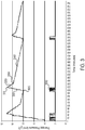
- FIG. 3 A graph showing the results of the implementation of the algorithm of the present invention is shown in Figure 3 .
- the bottom plot shows events. Pressure increases are triggered when the event density exceeds a certain threshold, and the pressure continues to rise as long as at least one of the pressure increase algorithm triggering criteria are met. This phase of the cycle is shown by reference number 310 in Figure 3 . Because the pressure increases are aggressive and much higher than the pressure decreases generated by the pressure decrease algorithm, the increases in pressure during portion 310 of the cycle will overpower the much smaller decreases in pressure produced by the pressure decrease algorithm.
- the criteria for determining the event density and resultant pressure increases is based on scientific observation of effective treatment regimens, many different criteria could be used to trigger increases in pressure.
- the following criteria are used by the pressure increase algorithm to determine if the pressure should be raised for any 1 minute evaluation cycle.
- the event density is evaluated every minute, using the most recent 1 minute and 6 minute windows. Pressure increases will only occur if there have been no central events during the most recent 1 minute and 6 minute windows. The following criteria in the preferred embodiment will trigger a pressure increase:
- the event density will continue to be evaluated every minute and the rise in pressure will stop once none of the criteria are met, at a peak pressure point shown by reference number 315 in Figure 3 .
- the pressure decrease algorithm is also evaluated every minute, although preferably staggered at 30 second intervals from the start of the pressure increase algorithm.
- the pressure decreases are relatively large, until the pressure transition point indicated by reference number 330 in Figure 3 has been reached.
- the larger pressure decreases during portion 320 of the cycle helps in achieving the first goal of the invention, that being to decrease discomfort experienced by the patient and to reduce the likelihood of arousal during the sleep session.
- Figure 3 shows treatFloor as reference number 305, and maxTreatPressure as reference number 315.
- 70% as the pressure transition point multiplier is arbitrary and could vary from that value, but should be most effective in the 60% - 75% range.
- the size of the pressure decreases in the initial rapid descent portion of the cycle 320 is given by the following criteria:
- the decreases in pressure are calculated using the same criteria as the pressure decreases prior to the pressure reaching pressure transition point 330, but are reduced by a percentage reduction to avoid having the event density rise sooner the necessary.
- the rate of decrease after the pressure transition point 330 has been reached is reduced by 50% of the decrease calculated by the pressure reduction algorithm. If no central events are present in the most recent 1 minute window, the rate of reduction as calculated by the pressure reduction algorithm is reduced by 85%. The portion of the cycle having reduced reductions in pressure is shown by reference number 340 in Figure 3 .
- the percentages of reduction have been chosen arbitrarily and could be set to any value, as long as the average rate of reduction in the pressure in portion 340 of the cycle is less than the average rate of reduction in the pressure in portion 320 of the cycle, as shown in Figure 3 .
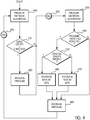
- FIG. 4 shows a flowchart of the auto adjust module of the present invention. As previously discussed, it consists of pressure increase algorithm 400 and pressure decrease algorithm 430.
- pressure increase algorithm 400 gathers data regarding events which have occurred during the most recent 1 minute and 6 minute windows.
- box 410 a calculation is made to determine if the event density has exceeded the threshold for any of the criteria mentioned above. If the event density has exceeded the threshold this indicates that cycle is in portion 310 as shown in Figure 3 . Control then passes to box 420, where the increase in pressure is implemented and thereafter to a 30 second delay at 495, after which the pressure decrease algorithm 430 will be executed. If, in box 410, it is determined that the event density has not exceed the threshold specified by any of the criteria, then control proceeds directly to the 30 second delay 495.
- the pressure decrease algorithm determines the pressure decrease based upon the criteria mentioned above.
- box 440 it is determined if the pressure transition point 330 has been reached. If not, control proceeds to box 480, where the calculated decrease in pressure is implemented. It should be noted that, if the "No" branch of box 440 is taken, this indicates that the cycle is either in portion 310 or 320 as shown in Figure 3 . If pressure transition point 330 has been reached (i.e., the pressure has previously been lowered to a level at or below pressure transition point 330), control proceeds to box 450, where it is determined if central events are present. If central events have been detected, control proceeds to box 460, where the rate of decrease in pressure is reduced by 50%.
- control proceeds to box 470, where the rate of decrease in pressure is reduced by 85%. In either case, control, from box 460 or 470, passes to box 480, where the decrease in pressure is implemented. Thereafter, control proceeds to 30 second delay 490 after which the pressure increase algorithm 400 is again executed.
- each algorithm is executed approximately once per minute, but at staggered intervals. This allows any previous changes in air pressure to become settled before another change in pressure is undertaken.
- figure 4 shows an implementation wherein the pressure decrease algorithm is executed even during portion 310 of the cycle. Many implementations are possible in which a more linear execution of the pressure increase algorithm and pressure decrease algorithm are utilized. Such implementations also fall within the scope of the invention.
- the invention is claimed in terms of net changes in pressure, regardless of whether, for example, a net increase in pressure consists of large increases and small decreases implemented concurrently.
Landscapes
- Health & Medical Sciences (AREA)
- Life Sciences & Earth Sciences (AREA)
- Public Health (AREA)
- Engineering & Computer Science (AREA)
- Anesthesiology (AREA)
- Biomedical Technology (AREA)
- Heart & Thoracic Surgery (AREA)
- Pulmonology (AREA)
- Animal Behavior & Ethology (AREA)
- Hematology (AREA)
- General Health & Medical Sciences (AREA)
- Emergency Medicine (AREA)
- Veterinary Medicine (AREA)
- Percussion Or Vibration Massage (AREA)
- Massaging Devices (AREA)
- Measurement Of The Respiration, Hearing Ability, Form, And Blood Characteristics Of Living Organisms (AREA)
Description
- This invention is related to the field of breathing therapy machines, such as continuous positive airway pressure (CPAP) machines, which deliver air at a constant therapy pressure, and bi-level positive airway pressure (Bi-PAP) machines, which deliver air at a therapy pressure for inhalation and at a reduced pressure for exhalation. Such machines are typically used to treat patients suffering from breathing disorders, such as hypopnea or apnea. Specifically, the invention is related to such machines having an auto-adjust feature for automatically adjusting the therapy pressure delivered by the machine based on patient response.
- Continuous Positive Airways Pressure (CPAP) machines are well known in the art for use in the treatment of a number of respiratory conditions, such as sleep apnea and hypopnea, by supplying a continuous positive pressure to a patient's airway while the patient sleeps. A typical CPAP apparatus is programmed with a therapy pressure, and is able to maintain the set pressure (measured either at the mask or at a base unit) during the inhalation and exhalation phases of the breathing cycle. The pressure setting is typically programmed via a control on the unit. Bi-PAP machines will typically vary the positive pressure delivered to the user during the inhalation and exhalation phases of the breathing cycle. Typically, Bi-PAP machines deliver a lower pressure during the exhalation phase of the breathing cycle, to make it easier or less uncomfortable for patients to exhale while using the machine. The Bi-PAP machine is typically programmed with a therapy pressure, which is used as the inhalation pressure, while the exhalation pressure is typically a standard difference from the inhalation pressure.
WO 2009/026582 A1 discloses systems and methods for adjusting a desired pressure in a positive airway pressure (PAP) device are provided. The method includes: a) providing breathing gas under positive pressure to a patient via a PAP device based on current desired pressure, b) monitoring a characteristic of the breathing gas, patient, or PAP device indicative of respiration, c) creating a breathing cycle signal having a first level associated with inhalation and a second level associated with exhalation, the signal being based on the monitored respiration characteristic, d) performing an abnormal breathing check based on the monitored respiration characteristic and the breathing cycle signal, and e) if abnormal breathing is detected, increasing the current desired pressure until a maximum desired pressure is reached, otherwise, decreasing the current desired pressure until a minimum desired pressure is reached.US 2005/211248 A1 discloses a method for controlling the pressure supplied by a CPAP device. The method comprises repeated measurement of a respiratory air flow during operation of the device and determining at least one respiratory event from the measured time-dependent behavior of the respiratory flow, the respiratory event representing an indication that the pressure supplied by the CPAP device is too low. -
Figure 1 shows a schematic view of a typical prior art CPAP / Bi-PAPmachine 30. Positive pressure is maintained by regulatedblower 40, under control ofmotor control circuitry 38. Blower 40 supplies a pressurized flow of air to a mask connected via the flexible tube (not shown) to blower 40. Regardless of whether the device is a CPAP machine or a Bi-PAP machine,microprocessor 34, in accordance with normal operating programming stored inmemory 36 produces a motor control signal which is interpreted bymotor control circuitry 38.Motor control circuitry 38 translates motor control signal 37 into electrical impulses that control the speed ofblower 40 to produce the desired pressure throughflow element 42 and ultimately to the user of the device. The machine may be equipped with various sensors, such aspressure sensor 44 andflow sensor 46 to aid in the detection of sleep events. Control and programming of the device is accomplished viauser interface 32. - Prior art breathing therapy machines may also be equipped with an auto-adjust feature. The auto-adjust feature allows the breathing therapy machine to adjust the pressure automatically in response to the sensed condition of the patient, specifically, in response to sensed apneas, hypopneas or episodes of periodic breathing. In a typical prior art implementation of this feature, the therapy pressure is quickly raised in response to sensed events, and then lowered in a linear manner until further events occur, at which time the cycle repeats. The auto-adjust feature is provided to make use of the machine more comfortable for the user and to avoid providing a higher pressure than is necessary to prevent or reduce events.
-
Figure 2 shows a pressure graph produced by a common implementation of the auto-adjust feature. When the device detects a certain density of events (i.e., a certain number of events over a pre-determined period of time), for example, as shown inFigure 2 asreference number 200, the pressure is aggressively raised as shown byreference number 210, until the events are eliminated or until the density of events is reduced below an acceptable level. Thereafter, the pressure is reduced in constant intervals at a slower rate as shown byreference number 220. - There are two problems with the prior art auto-adjust algorithm. First, the aggressive raising of
pressure 210 often causes the delivered therapy pressure to overshoot the pressure needed to reduce or eliminate the events, and the slow rate of lowering thepressure 220 causes the therapy pressure to remain at a this higher level longer than necessary. This tends to cause the patient discomfort and may cause arousals during sleep. Secondly, the lowering of the pressure at the constant rate eventually allows the events to start occurring at a density high enough to cause the aggressive raising ofpressure 210 to recur and begin the cycle again. This cycling over the course of a sleep session causes disruption in the patient's sleep. - Therefore, it would be desirable to provide an improved auto-adjust algorithm that alleviates these deficiencies in the prior art devices.
- The present invention is a breathing therapy device having an improved auto-adjust algorithm that addresses the identified deficiencies in the prior art devices. When a predetermined density of events is detected, the improved auto-adjust algorithm acts identically to the prior art algorithm in aggressively raising the pressure to eliminate or reduce the events below the density threshold. Thereafter, however, instead of lowering the pressure in constant intervals, the pressure is quickly lowered (i.e., reduced at greater intervals) until a "transition" pressure threshold is reached. This addresses the first deficiency of the prior art algorithms, that being having the pressure remain at a higher than required level for longer than necessary.
- After reaching the transition pressure transition point, the pressure is thereafter reduced in much smaller intervals, which tends to reduce the average rate of pressure reduction and to elongate the cycle such that the therapy pressure takes a much longer time to reach a pressure at which events previously occurred at a density high enough to restart the cycle. This has the effect of causing the cycle to repeat much less frequently than with the prior art algorithm, thus providing the patient with a sleep session having fewer disruptions.
-
-
Figure 1 is a schematic diagram of a prior art breathing therapy machine. -
Figure 2 is a graph showing pressure over time for a typical prior art implementation of an auto-adjust algorithm. -
Figure 3 is a graph showing pressure over time for the auto-adjust algorithm of the present invention. -
Figure 4 is a flow chart showing the logic flow of the auto-adjust algorithm of the present invention. - The improved auto-adjust algorithm of the present invention can be implemented in a typical prior-art device as a software module stored in
memory 36. In the preferred embodiment, the algorithm is essentially two algorithms working concurrently, one to determine if the pressure should be raised, and the other to determine if the pressure should be lowered. As one of skill in the art would realize, this is only one way of implementing the invention, and other implementations may be used without deviating from the spirit or scope of the invention. In the preferred embodiment, both the pressure increase algorithm and the pressure decrease algorithm evaluate whether the pressure should be changed by determining the event density. Both algorithms are evaluated once a minute and look at the most recent 1 minute and 6 minute windows, as will be described below, to determine the event density. Preferably, the algorithms will be staggered to run at 30 second intervals. - A graph showing the results of the implementation of the algorithm of the present invention is shown in
Figure 3 . The bottom plot shows events. Pressure increases are triggered when the event density exceeds a certain threshold, and the pressure continues to rise as long as at least one of the pressure increase algorithm triggering criteria are met. This phase of the cycle is shown byreference number 310 inFigure 3 . Because the pressure increases are aggressive and much higher than the pressure decreases generated by the pressure decrease algorithm, the increases in pressure duringportion 310 of the cycle will overpower the much smaller decreases in pressure produced by the pressure decrease algorithm. - Although in the preferred embodiment, the criteria for determining the event density and resultant pressure increases is based on scientific observation of effective treatment regimens, many different criteria could be used to trigger increases in pressure. In the preferred embodiment, the following criteria are used by the pressure increase algorithm to determine if the pressure should be raised for any 1 minute evaluation cycle.
- As previously stated, the event density is evaluated every minute, using the most recent 1 minute and 6 minute windows. Pressure increases will only occur if there have been no central events during the most recent 1 minute and 6 minute windows. The following criteria in the preferred embodiment will trigger a pressure increase:
- more than 2 obstructive events in the last 1 minute window (pressure rises by 1 cmH2O);
- more than 1 obstructive event in the last 1 minute window and more than 2 obstructive events in the last 6 minute window (pressure rises by 1 cmH2O); or
- 2 obstructive events in the last 1 minute window and 2 obstructive events in the last 6 minute window (pressure rises by of .5 cmH2O).
- 1 or more RERA (Respiratory Effort Related Arousal) events in the last 1 minute window and 2 or more RERA events in the last 6 minute window (Pressure rises by .2 cmH2O)
- The event density will continue to be evaluated every minute and the rise in pressure will stop once none of the criteria are met, at a peak pressure point shown by
reference number 315 inFigure 3 . - The pressure decrease algorithm is also evaluated every minute, although preferably staggered at 30 second intervals from the start of the pressure increase algorithm. During the initial phase of the pressure decrease portion of the cycle, as shown as
reference number 320 inFigure 3 , the pressure decreases are relatively large, until the pressure transition point indicated byreference number 330 inFigure 3 has been reached. The larger pressure decreases duringportion 320 of the cycle helps in achieving the first goal of the invention, that being to decrease discomfort experienced by the patient and to reduce the likelihood of arousal during the sleep session. - After
pressure transition point 330 has been reached, the pressure is decreased in much smaller increments, during the portion of the cycle indicated byreference number 340 inFigure 3 . Thepressure transition point 330 is calculated in the preferred embodiment using the following equation:
Figure 3 shows treatFloor asreference number 305, and maxTreatPressure asreference number 315. As one of skill in the art would recognize, the selection of 70% as the pressure transition point multiplier is arbitrary and could vary from that value, but should be most effective in the 60% - 75% range. - The size of the pressure decreases in the initial rapid descent portion of the
cycle 320, in the preferred embodiment, is given by the following criteria: - more than 3 central events during the last 6 minute window (pressure decreases by 1.2 cmH2O);
- at least 1 central event during the last 1 minute window (pressure decreases by .2 cmH2O)
- 1 obstructive event and no central events in the last 1 minute window and less than 2 obstructive events and no central events in the last 6 minute window (pressure decrease by .1 cmH2O)
- no obstructive or central events in the last 1 minute or 6 minute windows (pressure decreases by .1 cmH2O)
- Once
pressure transition point 330 has been reached, the decreases in pressure are calculated using the same criteria as the pressure decreases prior to the pressure reachingpressure transition point 330, but are reduced by a percentage reduction to avoid having the event density rise sooner the necessary. In the preferred embodiment, if central events are present in the most recent 1 minute window, the rate of decrease after thepressure transition point 330 has been reached is reduced by 50% of the decrease calculated by the pressure reduction algorithm. If no central events are present in the most recent 1 minute window, the rate of reduction as calculated by the pressure reduction algorithm is reduced by 85%. The portion of the cycle having reduced reductions in pressure is shown byreference number 340 inFigure 3 . Note that, in the preferred embodiment of the invention, the percentages of reduction have been chosen arbitrarily and could be set to any value, as long as the average rate of reduction in the pressure inportion 340 of the cycle is less than the average rate of reduction in the pressure inportion 320 of the cycle, as shown inFigure 3 . - It should also be noted that, as the pressure is constantly decreasing, it is likely that the pressure will reach a point where the event density rises, as shown in
Figure 3 asreference 300, causing the pressure increase algorithm to generate pressure increases, as shown asreference number 310 inFigure 3 . However, in extending the time until the event density rises, the second goal of the invention has been met, that being that the cycle shown inFigure 3 occurs less frequently during the course of the sleep session. - It should also be noted that current state-of-the-art machines can only make pressure changes in approximately . 1 cmH2O increments. Because many of the changes during
portion 340 of the cycle are less than this amount, these pressure changes may be buffered until they accumulate to . 1 cmH2O or greater. This buffering of pressure changes does not change the overall average rate of reduction in the pressure. -
Figure 4 shows a flowchart of the auto adjust module of the present invention. As previously discussed, it consists ofpressure increase algorithm 400 andpressure decrease algorithm 430. At the start,pressure increase algorithm 400 gathers data regarding events which have occurred during the most recent 1 minute and 6 minute windows. Inbox 410, a calculation is made to determine if the event density has exceeded the threshold for any of the criteria mentioned above. If the event density has exceeded the threshold this indicates that cycle is inportion 310 as shown inFigure 3 . Control then passes tobox 420, where the increase in pressure is implemented and thereafter to a 30 second delay at 495, after which thepressure decrease algorithm 430 will be executed. If, inbox 410, it is determined that the event density has not exceed the threshold specified by any of the criteria, then control proceeds directly to the 30second delay 495. - In
box 430 the pressure decrease algorithm determines the pressure decrease based upon the criteria mentioned above. Inbox 440, it is determined if thepressure transition point 330 has been reached. If not, control proceeds tobox 480, where the calculated decrease in pressure is implemented. It should be noted that, if the "No" branch ofbox 440 is taken, this indicates that the cycle is either inportion Figure 3 . Ifpressure transition point 330 has been reached (i.e., the pressure has previously been lowered to a level at or below pressure transition point 330), control proceeds tobox 450, where it is determined if central events are present. If central events have been detected, control proceeds tobox 460, where the rate of decrease in pressure is reduced by 50%. If, inbox 450, no central events have been detected, then control proceeds tobox 470, where the rate of decrease in pressure is reduced by 85%. In either case, control, frombox box 480, where the decrease in pressure is implemented. Thereafter, control proceeds to 30second delay 490 after which thepressure increase algorithm 400 is again executed. - With the 30
second delay pressure increase algorithm 400 andpressure decrease algorithm 430, each algorithm is executed approximately once per minute, but at staggered intervals. This allows any previous changes in air pressure to become settled before another change in pressure is undertaken. - The invention has been explained in terms of a specific implementation utilizing specific numbers as criteria for pressure changes. As one of skill in the art will recognize that these specific values are merely exemplars and may be varied without deviating from the scope of the invention. In addition,
figure 4 shows an implementation wherein the pressure decrease algorithm is executed even duringportion 310 of the cycle. Many implementations are possible in which a more linear execution of the pressure increase algorithm and pressure decrease algorithm are utilized. Such implementations also fall within the scope of the invention. The invention is claimed in terms of net changes in pressure, regardless of whether, for example, a net increase in pressure consists of large increases and small decreases implemented concurrently.
Claims (13)
- A breathing therapy machine having an optimized auto-adjust capability comprising:a. a blower, for delivering air to a user of said device at a pressure;b. a processor, for controlling said blower;c. non-volatile memory, accessible by said processor, said non-volatile memory containing operational programming; andd. an auto-adjust module, stored in said non-volatile memory as part of said operational programming, said auto-adjust module being configured for controlling said pressure of said air, characterised in thatsaid auto-adjust module is configured to raise said pressure in response to an event density that reaches or exceeds a predetermined pressure increase threshold, said pressure being raised until said pressure has reached a peak pressure;
said auto-adjust module is configured to lower said pressure from said peak pressure at a first averaged rate of decrease until said pressure reaches a pressure transition point, wherein said pressure transition point is calculated as a percentage of the difference between said peak pressure and a lowest pressure reached before said peak pressure was reached at which said event density had reached or exceeded said predetermined pressure increase threshold; and
said auto-adjust module is configured to thereafter lower said pressure at a second averaged rate of decrease, said second averaged rate of decrease being lower than said first averaged rate of decrease. - The breathing therapy machine of claim 1 wherein said event density reaches or exceeds said pressure increase threshold when one or more criteria in a set of pressure increase criteria is met.
- The breathing therapy machine of claim 2 wherein said pressure increase criteria are evaluated every minute over the most recent 1 minute and 6 minute windows of time.
- The breathing therapy machine of claim 2 wherein said peak pressure is reached when said event density falls below said pressure increase threshold.
- The breathing therapy machine of claim 4 wherein said auto-adjust module is configured to lower said pressure in accordance with a set of pressure decrease criteria.
- The breathing therapy machine of claim 5 wherein said pressure decrease criteria are evaluated every minute over the most recent 1 minute and 6 minute windows of time.
- The breathing therapy machine of claim 5 wherein said pressure decrease criteria and said pressure increase criteria are evaluated at intervals which are staggered from each other, wherein optionally said pressure decrease criteria and said pressure increase criteria are evaluated at intervals which are staggered 30 seconds from each other, wherein more optionally the range of said percentage is 60% - 75%.
- The breathing therapy machine of claim 5 wherein said pressure decreases are calculated based upon periodic re-evaluation of said pressure decrease criteria.
- The breathing therapy machine of claim 8 wherein pressure decreases after said pressure has reached said pressure transition point are determined by said periodic evaluation of said pressure decrease criteria and having a percentage reduction applied to the calculated pressure decrease.
- The breathing therapy machine of claim 9 wherein said pressure decreases before said pressure has reached said pressure transition point may be averaged to obtain said first averaged rate of decrease and further wherein said pressure decreases after said pressure has reached said pressure transition point may be averaged to obtain said second averaged rate of decrease.
- The breathing therapy machine of claim 8 wherein said percentage reduction of pressure decreases after said pressure has reached said pressure transition point are a function of the type of events sensed as said pressure is decreased.
- The breathing therapy machine of claim 11 wherein:said percentage reduction is 50% if central type events have been detected during a most recent window of time; andsaid percentage reduction is 85% if no central type events have been detected during said most recent window of time, wherein optionally said most recent window of time is of a pre-determined length.
- The breathing therapy machine of claim 1 further comprising:
one or more sensors capable of sensing events, said events including hypopneas and apneas and further wherein said events may be of the obstructive or central type.
Applications Claiming Priority (2)
| Application Number | Priority Date | Filing Date | Title |
|---|---|---|---|
| US14/337,897 US9937309B2 (en) | 2014-07-22 | 2014-07-22 | Method of optimizing therapy pressure in a breathing therapy machine having an auto-adjust feature |
| PCT/US2015/041333 WO2016014532A1 (en) | 2014-07-22 | 2015-07-21 | Method of optimizing therapy pressure in a breathing therapy machine having an auto-adjust feature |
Publications (3)
| Publication Number | Publication Date |
|---|---|
| EP3171923A1 EP3171923A1 (en) | 2017-05-31 |
| EP3171923A4 EP3171923A4 (en) | 2018-02-28 |
| EP3171923B1 true EP3171923B1 (en) | 2018-12-19 |
Family
ID=55163634
Family Applications (1)
| Application Number | Title | Priority Date | Filing Date |
|---|---|---|---|
| EP15825128.0A Active EP3171923B1 (en) | 2014-07-22 | 2015-07-21 | Breathing therapy machine having an auto-adjust module for optimizing therapy pressure |
Country Status (3)
| Country | Link |
|---|---|
| US (1) | US9937309B2 (en) |
| EP (1) | EP3171923B1 (en) |
| WO (1) | WO2016014532A1 (en) |
Families Citing this family (1)
| Publication number | Priority date | Publication date | Assignee | Title |
|---|---|---|---|---|
| WO2022175487A1 (en) * | 2021-02-22 | 2022-08-25 | Koninklijke Philips N.V. | Method for providing comfort feature in a pressure support device and pressure support device including same |
Family Cites Families (29)
| Publication number | Priority date | Publication date | Assignee | Title |
|---|---|---|---|---|
| EP2324765B1 (en) * | 1993-11-05 | 2015-10-07 | ResMed Limited | Control of CPAP treatment |
| US6105575A (en) * | 1994-06-03 | 2000-08-22 | Respironics, Inc. | Method and apparatus for providing positive airway pressure to a patient |
| US6932084B2 (en) | 1994-06-03 | 2005-08-23 | Ric Investments, Inc. | Method and apparatus for providing positive airway pressure to a patient |
| US5537997A (en) * | 1995-01-26 | 1996-07-23 | Respironics, Inc. | Sleep apnea treatment apparatus and passive humidifier for use therewith |
| EP0788805A3 (en) | 1996-02-06 | 1998-05-13 | DeVilbiss Health Care, Inc. | Control for CPAP apparatus |
| FR2789593B1 (en) * | 1999-05-21 | 2008-08-22 | Mallinckrodt Dev France | APPARATUS FOR SUPPLYING AIR PRESSURE TO A PATIENT WITH SLEEP DISORDERS AND METHODS OF CONTROLLING THE SAME |
| US6467477B1 (en) * | 1999-03-26 | 2002-10-22 | Respironics, Inc. | Breath-based control of a therapeutic treatment |
| US6532960B1 (en) * | 2000-07-10 | 2003-03-18 | Respironics, Inc. | Automatic rise time adjustment for bi-level pressure support system |
| US7168429B2 (en) * | 2001-10-12 | 2007-01-30 | Ric Investments, Llc | Auto-titration pressure support system and method of using same |
| US7938114B2 (en) * | 2001-10-12 | 2011-05-10 | Ric Investments Llc | Auto-titration bi-level pressure support system and method of using same |
| US7661426B2 (en) | 2002-11-19 | 2010-02-16 | Michael Lauk | Method for controlling the pressure supplied by a CPAP device, CPAP device and storage medium |
| JP2006520227A (en) * | 2003-03-17 | 2006-09-07 | エムアーペー メディツィンテクノロジー ゲゼルシャフト・ミット・ベシュレンクテル・ハフツング | Method and apparatus for titrating a physiological measurement signal in conjunction with observing a patient for sleep-related breathing disorders |
| AU2003903138A0 (en) * | 2003-06-20 | 2003-07-03 | Resmed Limited | Method and apparatus for improving the comfort of cpap |
| DE102006006632B4 (en) | 2005-02-10 | 2026-05-07 | Löwenstein Medical Technology S.A. | Device for ventilation and method for controlling a ventilator |
| EP1893264B1 (en) * | 2005-06-14 | 2016-02-24 | ResMed Limited | Acclimatization therapy for first time cpap and niv users |
| US8316847B2 (en) | 2006-09-01 | 2012-11-27 | Ventific Holdings Pty Ltd | Automatic positive airway pressure therapy through the nose or mouth for treatment of sleep apnea and other respiratory disorders |
| US8261742B2 (en) | 2007-08-23 | 2012-09-11 | Invacare Corporation | Method and apparatus for adjusting desired pressure in positive airway pressure devices |
| JP5715066B2 (en) * | 2008-12-19 | 2015-05-07 | コーニンクレッカ フィリップス エヌ ヴェ | System and method for treating lung disease using positive airway pressure support |
| BRPI0917726A2 (en) * | 2008-12-19 | 2016-02-16 | Koninkl Philips Electronics Nv | pressure support system to treat lung disease |
| BRPI1005998B8 (en) * | 2009-02-25 | 2021-06-22 | Koninl Philips Electronics Nv | pressure support system |
| NZ599917A (en) | 2009-11-16 | 2014-10-31 | Resmed Ltd | Methods and apparatus for adaptable pressure treatment of sleep disordered breathing |
| US8555880B2 (en) | 2010-07-28 | 2013-10-15 | Devilbiss Healthcare, Llc | Variable transition pressure profiles for a bi-level breathing therapy machine |
| US8991392B1 (en) * | 2010-12-21 | 2015-03-31 | Fisher & Paykel Healthcare Limited | Pressure adjustment method for CPAP machine |
| EP2830688B1 (en) * | 2012-03-30 | 2019-01-02 | Koninklijke Philips N.V. | Starting pressure for respiratory therapy devices |
| US10369310B2 (en) * | 2014-03-05 | 2019-08-06 | ResMed Pty Ltd | Method and apparatus for treatment of respiratory disorders |
| AU2015228507B2 (en) * | 2014-03-10 | 2019-12-12 | Fisher & Paykel Healthcare Limited | Pressure range adjustment for respiratory therapy device |
| FR3019468B1 (en) * | 2014-04-02 | 2024-07-12 | Fisher & Paykel Healthcare Ltd | VARIABLE POSITIVE PRESSURE VENTILATION SUPPLY DEPENDING ON RESPIRATORY DISORDERS AND THE AWAKE STATE |
| US20150374940A1 (en) * | 2014-06-26 | 2015-12-31 | Devilbiss Healthcare Llc | System and Method for Acclimating A New User To A Breathing Therapy Machine |
| US10286168B2 (en) * | 2014-07-17 | 2019-05-14 | Devilbiss Healthcare Llc | Phenotyping of sleep breathing disorders using a breathing therapy machine |
-
2014
- 2014-07-22 US US14/337,897 patent/US9937309B2/en active Active
-
2015
- 2015-07-21 EP EP15825128.0A patent/EP3171923B1/en active Active
- 2015-07-21 WO PCT/US2015/041333 patent/WO2016014532A1/en not_active Ceased
Non-Patent Citations (1)
| Title |
|---|
| None * |
Also Published As
| Publication number | Publication date |
|---|---|
| WO2016014532A1 (en) | 2016-01-28 |
| US9937309B2 (en) | 2018-04-10 |
| EP3171923A4 (en) | 2018-02-28 |
| EP3171923A1 (en) | 2017-05-31 |
| US20160022937A1 (en) | 2016-01-28 |
Similar Documents
| Publication | Publication Date | Title |
|---|---|---|
| JP5810191B2 (en) | Macro-control of therapy for sleep breathing disorders | |
| CA2808014C (en) | Apparatus and method for providing gases to a user | |
| US10625036B2 (en) | Multi-night titration pressure determination | |
| CA2463088A1 (en) | Auto-titration pressure support system and method of using same | |
| CN102711888A (en) | Methods and devices for adaptive compression therapy of sleep-disordered breathing | |
| EP2598191A1 (en) | Variable transition pressure profiles for a bi-level breathing therapy machine | |
| US12558503B2 (en) | Bilevel respiratory therapy system, controller and method | |
| US9937309B2 (en) | Method of optimizing therapy pressure in a breathing therapy machine having an auto-adjust feature | |
| EP3193713B1 (en) | Breathing therapy machine having means for detecting an inspiratory flow limitation during sleep-disordered breathing | |
| CN108619598A (en) | A kind for the treatment of pressure of lung ventilator is from titration system and method |
Legal Events
| Date | Code | Title | Description |
|---|---|---|---|
| STAA | Information on the status of an ep patent application or granted ep patent |
Free format text: STATUS: THE INTERNATIONAL PUBLICATION HAS BEEN MADE |
|
| PUAI | Public reference made under article 153(3) epc to a published international application that has entered the european phase |
Free format text: ORIGINAL CODE: 0009012 |
|
| STAA | Information on the status of an ep patent application or granted ep patent |
Free format text: STATUS: REQUEST FOR EXAMINATION WAS MADE |
|
| 17P | Request for examination filed |
Effective date: 20161220 |
|
| AK | Designated contracting states |
Kind code of ref document: A1 Designated state(s): AL AT BE BG CH CY CZ DE DK EE ES FI FR GB GR HR HU IE IS IT LI LT LU LV MC MK MT NL NO PL PT RO RS SE SI SK SM TR |
|
| AX | Request for extension of the european patent |
Extension state: BA ME |
|
| DAV | Request for validation of the european patent (deleted) | ||
| DAX | Request for extension of the european patent (deleted) | ||
| A4 | Supplementary search report drawn up and despatched |
Effective date: 20180130 |
|
| RIC1 | Information provided on ipc code assigned before grant |
Ipc: A61M 16/00 20060101AFI20180124BHEP |
|
| GRAP | Despatch of communication of intention to grant a patent |
Free format text: ORIGINAL CODE: EPIDOSNIGR1 |
|
| STAA | Information on the status of an ep patent application or granted ep patent |
Free format text: STATUS: GRANT OF PATENT IS INTENDED |
|
| INTG | Intention to grant announced |
Effective date: 20180629 |
|
| GRAS | Grant fee paid |
Free format text: ORIGINAL CODE: EPIDOSNIGR3 |
|
| GRAA | (expected) grant |
Free format text: ORIGINAL CODE: 0009210 |
|
| STAA | Information on the status of an ep patent application or granted ep patent |
Free format text: STATUS: THE PATENT HAS BEEN GRANTED |
|
| AK | Designated contracting states |
Kind code of ref document: B1 Designated state(s): AL AT BE BG CH CY CZ DE DK EE ES FI FR GB GR HR HU IE IS IT LI LT LU LV MC MK MT NL NO PL PT RO RS SE SI SK SM TR |
|
| REG | Reference to a national code |
Ref country code: GB Ref legal event code: FG4D |
|
| REG | Reference to a national code |
Ref country code: CH Ref legal event code: EP |
|
| REG | Reference to a national code |
Ref country code: IE Ref legal event code: FG4D |
|
| REG | Reference to a national code |
Ref country code: DE Ref legal event code: R096 Ref document number: 602015022025 Country of ref document: DE |
|
| REG | Reference to a national code |
Ref country code: AT Ref legal event code: REF Ref document number: 1078003 Country of ref document: AT Kind code of ref document: T Effective date: 20190115 |
|
| REG | Reference to a national code |
Ref country code: NL Ref legal event code: MP Effective date: 20181219 |
|
| PG25 | Lapsed in a contracting state [announced via postgrant information from national office to epo] |
Ref country code: LV Free format text: LAPSE BECAUSE OF FAILURE TO SUBMIT A TRANSLATION OF THE DESCRIPTION OR TO PAY THE FEE WITHIN THE PRESCRIBED TIME-LIMIT Effective date: 20181219 Ref country code: NO Free format text: LAPSE BECAUSE OF FAILURE TO SUBMIT A TRANSLATION OF THE DESCRIPTION OR TO PAY THE FEE WITHIN THE PRESCRIBED TIME-LIMIT Effective date: 20190319 Ref country code: FI Free format text: LAPSE BECAUSE OF FAILURE TO SUBMIT A TRANSLATION OF THE DESCRIPTION OR TO PAY THE FEE WITHIN THE PRESCRIBED TIME-LIMIT Effective date: 20181219 Ref country code: LT Free format text: LAPSE BECAUSE OF FAILURE TO SUBMIT A TRANSLATION OF THE DESCRIPTION OR TO PAY THE FEE WITHIN THE PRESCRIBED TIME-LIMIT Effective date: 20181219 Ref country code: HR Free format text: LAPSE BECAUSE OF FAILURE TO SUBMIT A TRANSLATION OF THE DESCRIPTION OR TO PAY THE FEE WITHIN THE PRESCRIBED TIME-LIMIT Effective date: 20181219 Ref country code: BG Free format text: LAPSE BECAUSE OF FAILURE TO SUBMIT A TRANSLATION OF THE DESCRIPTION OR TO PAY THE FEE WITHIN THE PRESCRIBED TIME-LIMIT Effective date: 20190319 |
|
| REG | Reference to a national code |
Ref country code: LT Ref legal event code: MG4D |
|
| REG | Reference to a national code |
Ref country code: AT Ref legal event code: MK05 Ref document number: 1078003 Country of ref document: AT Kind code of ref document: T Effective date: 20181219 |
|
| PG25 | Lapsed in a contracting state [announced via postgrant information from national office to epo] |
Ref country code: SE Free format text: LAPSE BECAUSE OF FAILURE TO SUBMIT A TRANSLATION OF THE DESCRIPTION OR TO PAY THE FEE WITHIN THE PRESCRIBED TIME-LIMIT Effective date: 20181219 Ref country code: GR Free format text: LAPSE BECAUSE OF FAILURE TO SUBMIT A TRANSLATION OF THE DESCRIPTION OR TO PAY THE FEE WITHIN THE PRESCRIBED TIME-LIMIT Effective date: 20190320 Ref country code: AL Free format text: LAPSE BECAUSE OF FAILURE TO SUBMIT A TRANSLATION OF THE DESCRIPTION OR TO PAY THE FEE WITHIN THE PRESCRIBED TIME-LIMIT Effective date: 20181219 Ref country code: RS Free format text: LAPSE BECAUSE OF FAILURE TO SUBMIT A TRANSLATION OF THE DESCRIPTION OR TO PAY THE FEE WITHIN THE PRESCRIBED TIME-LIMIT Effective date: 20181219 |
|
| PG25 | Lapsed in a contracting state [announced via postgrant information from national office to epo] |
Ref country code: NL Free format text: LAPSE BECAUSE OF FAILURE TO SUBMIT A TRANSLATION OF THE DESCRIPTION OR TO PAY THE FEE WITHIN THE PRESCRIBED TIME-LIMIT Effective date: 20181219 |
|
| PG25 | Lapsed in a contracting state [announced via postgrant information from national office to epo] |
Ref country code: ES Free format text: LAPSE BECAUSE OF FAILURE TO SUBMIT A TRANSLATION OF THE DESCRIPTION OR TO PAY THE FEE WITHIN THE PRESCRIBED TIME-LIMIT Effective date: 20181219 Ref country code: PL Free format text: LAPSE BECAUSE OF FAILURE TO SUBMIT A TRANSLATION OF THE DESCRIPTION OR TO PAY THE FEE WITHIN THE PRESCRIBED TIME-LIMIT Effective date: 20181219 Ref country code: IT Free format text: LAPSE BECAUSE OF FAILURE TO SUBMIT A TRANSLATION OF THE DESCRIPTION OR TO PAY THE FEE WITHIN THE PRESCRIBED TIME-LIMIT Effective date: 20181219 Ref country code: CZ Free format text: LAPSE BECAUSE OF FAILURE TO SUBMIT A TRANSLATION OF THE DESCRIPTION OR TO PAY THE FEE WITHIN THE PRESCRIBED TIME-LIMIT Effective date: 20181219 Ref country code: PT Free format text: LAPSE BECAUSE OF FAILURE TO SUBMIT A TRANSLATION OF THE DESCRIPTION OR TO PAY THE FEE WITHIN THE PRESCRIBED TIME-LIMIT Effective date: 20190419 |
|
| PG25 | Lapsed in a contracting state [announced via postgrant information from national office to epo] |
Ref country code: RO Free format text: LAPSE BECAUSE OF FAILURE TO SUBMIT A TRANSLATION OF THE DESCRIPTION OR TO PAY THE FEE WITHIN THE PRESCRIBED TIME-LIMIT Effective date: 20181219 Ref country code: SK Free format text: LAPSE BECAUSE OF FAILURE TO SUBMIT A TRANSLATION OF THE DESCRIPTION OR TO PAY THE FEE WITHIN THE PRESCRIBED TIME-LIMIT Effective date: 20181219 Ref country code: IS Free format text: LAPSE BECAUSE OF FAILURE TO SUBMIT A TRANSLATION OF THE DESCRIPTION OR TO PAY THE FEE WITHIN THE PRESCRIBED TIME-LIMIT Effective date: 20190419 Ref country code: SM Free format text: LAPSE BECAUSE OF FAILURE TO SUBMIT A TRANSLATION OF THE DESCRIPTION OR TO PAY THE FEE WITHIN THE PRESCRIBED TIME-LIMIT Effective date: 20181219 Ref country code: EE Free format text: LAPSE BECAUSE OF FAILURE TO SUBMIT A TRANSLATION OF THE DESCRIPTION OR TO PAY THE FEE WITHIN THE PRESCRIBED TIME-LIMIT Effective date: 20181219 |
|
| REG | Reference to a national code |
Ref country code: DE Ref legal event code: R097 Ref document number: 602015022025 Country of ref document: DE |
|
| PLBE | No opposition filed within time limit |
Free format text: ORIGINAL CODE: 0009261 |
|
| STAA | Information on the status of an ep patent application or granted ep patent |
Free format text: STATUS: NO OPPOSITION FILED WITHIN TIME LIMIT |
|
| PG25 | Lapsed in a contracting state [announced via postgrant information from national office to epo] |
Ref country code: DK Free format text: LAPSE BECAUSE OF FAILURE TO SUBMIT A TRANSLATION OF THE DESCRIPTION OR TO PAY THE FEE WITHIN THE PRESCRIBED TIME-LIMIT Effective date: 20181219 Ref country code: AT Free format text: LAPSE BECAUSE OF FAILURE TO SUBMIT A TRANSLATION OF THE DESCRIPTION OR TO PAY THE FEE WITHIN THE PRESCRIBED TIME-LIMIT Effective date: 20181219 |
|
| 26N | No opposition filed |
Effective date: 20190920 |
|
| PG25 | Lapsed in a contracting state [announced via postgrant information from national office to epo] |
Ref country code: MC Free format text: LAPSE BECAUSE OF FAILURE TO SUBMIT A TRANSLATION OF THE DESCRIPTION OR TO PAY THE FEE WITHIN THE PRESCRIBED TIME-LIMIT Effective date: 20181219 Ref country code: SI Free format text: LAPSE BECAUSE OF FAILURE TO SUBMIT A TRANSLATION OF THE DESCRIPTION OR TO PAY THE FEE WITHIN THE PRESCRIBED TIME-LIMIT Effective date: 20181219 |
|
| REG | Reference to a national code |
Ref country code: CH Ref legal event code: PL |
|
| PG25 | Lapsed in a contracting state [announced via postgrant information from national office to epo] |
Ref country code: TR Free format text: LAPSE BECAUSE OF FAILURE TO SUBMIT A TRANSLATION OF THE DESCRIPTION OR TO PAY THE FEE WITHIN THE PRESCRIBED TIME-LIMIT Effective date: 20181219 |
|
| REG | Reference to a national code |
Ref country code: BE Ref legal event code: MM Effective date: 20190731 |
|
| PG25 | Lapsed in a contracting state [announced via postgrant information from national office to epo] |
Ref country code: LU Free format text: LAPSE BECAUSE OF NON-PAYMENT OF DUE FEES Effective date: 20190721 Ref country code: BE Free format text: LAPSE BECAUSE OF NON-PAYMENT OF DUE FEES Effective date: 20190731 Ref country code: LI Free format text: LAPSE BECAUSE OF NON-PAYMENT OF DUE FEES Effective date: 20190731 Ref country code: CH Free format text: LAPSE BECAUSE OF NON-PAYMENT OF DUE FEES Effective date: 20190731 |
|
| PG25 | Lapsed in a contracting state [announced via postgrant information from national office to epo] |
Ref country code: IE Free format text: LAPSE BECAUSE OF NON-PAYMENT OF DUE FEES Effective date: 20190721 |
|
| PG25 | Lapsed in a contracting state [announced via postgrant information from national office to epo] |
Ref country code: CY Free format text: LAPSE BECAUSE OF FAILURE TO SUBMIT A TRANSLATION OF THE DESCRIPTION OR TO PAY THE FEE WITHIN THE PRESCRIBED TIME-LIMIT Effective date: 20181219 |
|
| PG25 | Lapsed in a contracting state [announced via postgrant information from national office to epo] |
Ref country code: HU Free format text: LAPSE BECAUSE OF FAILURE TO SUBMIT A TRANSLATION OF THE DESCRIPTION OR TO PAY THE FEE WITHIN THE PRESCRIBED TIME-LIMIT; INVALID AB INITIO Effective date: 20150721 Ref country code: MT Free format text: LAPSE BECAUSE OF FAILURE TO SUBMIT A TRANSLATION OF THE DESCRIPTION OR TO PAY THE FEE WITHIN THE PRESCRIBED TIME-LIMIT Effective date: 20181219 |
|
| PG25 | Lapsed in a contracting state [announced via postgrant information from national office to epo] |
Ref country code: MK Free format text: LAPSE BECAUSE OF FAILURE TO SUBMIT A TRANSLATION OF THE DESCRIPTION OR TO PAY THE FEE WITHIN THE PRESCRIBED TIME-LIMIT Effective date: 20181219 |
|
| PGFP | Annual fee paid to national office [announced via postgrant information from national office to epo] |
Ref country code: DE Payment date: 20250624 Year of fee payment: 11 |
|
| PGFP | Annual fee paid to national office [announced via postgrant information from national office to epo] |
Ref country code: GB Payment date: 20260622 Year of fee payment: 12 |
|
| PGFP | Annual fee paid to national office [announced via postgrant information from national office to epo] |
Ref country code: FR Payment date: 20260629 Year of fee payment: 12 |