EP3171623A1 - Method for interference coordination, network server and communication system using the same - Google Patents
Method for interference coordination, network server and communication system using the same Download PDFInfo
- Publication number
- EP3171623A1 EP3171623A1 EP15201567.3A EP15201567A EP3171623A1 EP 3171623 A1 EP3171623 A1 EP 3171623A1 EP 15201567 A EP15201567 A EP 15201567A EP 3171623 A1 EP3171623 A1 EP 3171623A1
- Authority
- EP
- European Patent Office
- Prior art keywords
- small cell
- macrocell
- abs pattern
- network server
- abs
- Prior art date
- Legal status (The legal status is an assumption and is not a legal conclusion. Google has not performed a legal analysis and makes no representation as to the accuracy of the status listed.)
- Granted
Links
Images



Classifications
-
- H—ELECTRICITY
- H04—ELECTRIC COMMUNICATION TECHNIQUE
- H04J—MULTIPLEX COMMUNICATION
- H04J11/00—Orthogonal multiplex systems, e.g. using WALSH codes
- H04J11/0023—Interference mitigation or co-ordination
- H04J11/005—Interference mitigation or co-ordination of intercell interference
- H04J11/0059—Out-of-cell user aspects
-
- H—ELECTRICITY
- H04—ELECTRIC COMMUNICATION TECHNIQUE
- H04W—WIRELESS COMMUNICATION NETWORKS
- H04W72/00—Local resource management
- H04W72/04—Wireless resource allocation
- H04W72/044—Wireless resource allocation based on the type of the allocated resource
- H04W72/0446—Resources in time domain, e.g. slots or frames
-
- H—ELECTRICITY
- H04—ELECTRIC COMMUNICATION TECHNIQUE
- H04W—WIRELESS COMMUNICATION NETWORKS
- H04W16/00—Network planning, e.g. coverage or traffic planning tools; Network deployment, e.g. resource partitioning or cells structures
- H04W16/02—Resource partitioning among network components, e.g. reuse partitioning
- H04W16/10—Dynamic resource partitioning
-
- H—ELECTRICITY
- H04—ELECTRIC COMMUNICATION TECHNIQUE
- H04W—WIRELESS COMMUNICATION NETWORKS
- H04W72/00—Local resource management
- H04W72/50—Allocation or scheduling criteria for wireless resources
- H04W72/52—Allocation or scheduling criteria for wireless resources based on load
-
- H—ELECTRICITY
- H04—ELECTRIC COMMUNICATION TECHNIQUE
- H04W—WIRELESS COMMUNICATION NETWORKS
- H04W16/00—Network planning, e.g. coverage or traffic planning tools; Network deployment, e.g. resource partitioning or cells structures
- H04W16/24—Cell structures
- H04W16/32—Hierarchical cell structures
-
- H—ELECTRICITY
- H04—ELECTRIC COMMUNICATION TECHNIQUE
- H04W—WIRELESS COMMUNICATION NETWORKS
- H04W84/00—Network topologies
- H04W84/02—Hierarchically pre-organised networks, e.g. paging networks, cellular networks, WLAN [Wireless Local Area Network] or WLL [Wireless Local Loop]
- H04W84/04—Large scale networks; Deep hierarchical networks
- H04W84/042—Public Land Mobile systems, e.g. cellular systems
- H04W84/045—Public Land Mobile systems, e.g. cellular systems using private Base Stations, e.g. femto Base Stations, home Node B
Definitions
- the disclosure relates in general to a method for interference coordination, and more particularly to a method for interference coordination related to macrocells and a network server.
- Small cells may be radio access nodes, for example, having a range of 10 meters to 2 kilometers, as compared to a macrocell, for example, having a range of a few tens of kilometers.
- Examples of small cells include femtocells, picocells, and microcells.
- a Node B is a 3G macrocell
- an eNode B is a Long Term Evolution (LTE) macrocell
- a Home Node B is a 3G femtocell
- a Home eNode B is a LTE femtocell.
- a user equipment such as a mobile phone
- a serving cell may suffer from interference caused by a neighboring small cell.
- signal from neighboring cell acts as interferer.
- the Signal-to-Noise ratio (SNR) may be poor not only because of the weak signal strength from the serving cell but also because of the interference.
- the disclosure is directed to a method for interference coordination, a network server and a communication system using the same.
- a method for interference coordination includes: receiving a first macrocell almost blank subframe (ABS) pattern from a first macrocell, receiving a second macrocell ABS pattern from a second macrocell, determining a first small cell ABS pattern for a first small cell according to the first macrocell ABS pattern and the second macrocell ABS pattern, and transmitting the first small cell ABS pattern to the first small cell.
- the first small cell is within a coverage of the first macrocell.
- a network server includes an ABS pattern management unit and a coordination unit.
- the ABS pattern management unit is configured to receive a first macrocell ABS pattern from a first macrocell, receive a second macrocell ABS pattern from a second macrocell, and transmit a first small cell ABS pattern to a first small cell.
- the coordination unit is configured to determine the first small cell ABS pattern for the first small cell according to the first macrocell ABS pattern and the second macrocell ABS pattern. The first small cell is within a coverage of the first macrocell.
- a communication system includes a network server, a first macrocell, a second macrocell, and a first small cell.
- the first macrocell is connected to the network server and is configured to transmit a first macrocell ABS pattern to the network server.
- the second macrocell is connected to the network server and is configured to transmit a second macrocell ABS pattern to the network server.
- the first small cell is connected to the network server and is within a coverage of the first macrocell.
- the network server is configured to determine a first small cell ABS pattern for the first small cell according to the first macrocell ABS pattern and the second macrocell ABS pattern, and transmit the first small cell ABS pattern to the first small cell.
- HetNet heterogeneous network
- a UE located near the boundary of the coverage of a small cell may suffer from interference induced from the macrocell.
- 3GPP has proposed enhanced inter-cell interference coordination (elCIC) to deal with this problem.
- An almost blank subframe (ABS) is used in elCIC to prevent the small cell from transmitting data at the same time as the serving macrocell.
- UEs connected to the small cell can thus receive data during such ABS to avoid interference from the macrocell.
- the macrocell may inform the small cell an ABS pattern to let the small cell know which time slots are available for data transmission.
- the macrocell serves as the control center to determine an ABS pattern for the small cells in its coverage area to prevent interference.
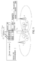
- FIG. 1 shows an example of interference between two neighboring small cells.
- small cell 11 and small cell 12 are in the coverage of the macrocell 1.
- Small cell 21 and small cell 22 are in the coverage of the macrocell 2.
- the coverage of a cell in this disclosure may be the area where received pilot signal strength from this cell is higher than a sensitive threshold of a mobile device.
- the macrocell 1 sets the ABS pattern as ⁇ 111110000 ⁇ for the small cells 11 and 12 (the '1' in the ABS pattern represents an ABS in which the small cell can transmit data).
- the macrocell 2 sets the ABS pattern as ⁇ 110011001 ⁇ for the small cells 21 and 22.
- the small cell 11 and the small cell 21 may transmit data simultaneously in the 1 st , 2 nd , and 5 th subframe. Therefore a UE in the intersection of the coverage areas of the small cells 11 and 21 may suffer from interference between these two small cells.
- FIG. 2 shows a communication system 9 according to an embodiment of this disclosure.
- the communication system 9 includes a network server 3, macrocells 1 and 2, small cells 11, 12, 21, and 22. In this example, two macrocells and four small cells are shown in the system. However, the number of macrocells and small cells are not limited thereto. There may also be two macrocells and one small cell in the communication system 9.
- the network server 3 may be connected to the macrocells 1 and 2 via the backhaul network, such as being connected via X2 interface as defined in 3GPP specification.
- the network server 3 may also be connected to the small cells 11, 12, 21 and 22 via the backhaul network.
- the network server 3 may be a self-organizing network (SON) server.
- SON is an automation technology designed to make the planning, configuration, management, optimization and healing of mobile radio access networks simpler and faster.
- the network server 3 acts as a mediator between the macrocells 1, 2 and the small cells 11, 12, 21, and 22.
- the network server 3 is able to integrate different ABS patterns information from the macrocells 1 and 2, and send appropriate control messages to the small cells 11, 12, 21, and 22, in order to avoid interference between neighboring small cells. The detailed description is given below.
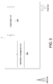
- FIG. 3 shows a block diagram illustrating a network server 3 according to an embodiment of this disclosure.
- the network server 3 includes an ABS pattern management unit 300 and a coordination unit 302.
- the ABS pattern management unit 300 is configured to receive a first macrocell ABS pattern MP1 from a first macrocell 1, receive a second macrocell ABS pattern MP2 from a second macrocell 2, and transmit a first small cell ABS pattern SP1 to a first small cell 11.
- the coordination unit 302 is configured to determine the first small cell ABS pattern SP1 for the first small cell 11 according to the first macrocell ABS pattern MP1 and the second macrocell ABS pattern MP2.
- the ABS pattern management unit 300 and the coordination unit 302 may be implemented by software, firmware, or hardware.
- the ABS pattern management unit 300 and the coordination unit 302 may be functional modules in a software program.
- the software program may be loaded from a memory device and executed by a processor.
- the ABS pattern management unit 300 and the coordination unit 302 may also be circuit blocks with the corresponding functions, such as application specific integrated circuits.
- FIG. 4 shows a flowchart illustrating an interference coordination method according to an embodiment of this disclosure.
- the interference coordination method includes the following steps: Step S201 receiving a first macrocell ABS pattern MP1 from a first macrocell 1.
- Step S202 receiving a second macrocell ABS pattern MP2 from a second macrocell 2.
- Step S211 determining a first small cell ABS pattern SP1 for a first small cell 11 according to the first macrocell ABS pattern MP1 and the second macrocell ABS pattern MP2.
- Step S213 transmitting the first small cell ABS pattern SP1 to the first small cell 11.
- the steps S201, S202, and S213 may be performed by the ABS pattern management unit 300, and the step S211 may be performed by the coordination unit 302. It should be noted that the step order shown in FIG. 4 is just exemplary rather than limiting.
- FIG. 5 shows a diagram illustrating a process of interference coordination according to an embodiment of this disclosure.
- Numbers 1-7 shown in the circles represent the steps executed in sequence in this exemplary process. In the following description, these numbers will be represented as steps S1-S7. It should be noted that the step order shown in FIG. 5 is just exemplary rather than limiting.
- Step S1 the first small cell 11 transmits a first request Req1 for ABS pattern information to the network server 3.
- the first small cell 11 may need to know what ABS pattern is available from its belonging first macrocell 1 in order to communicate with a UE with an appropriate ABS pattern.
- Step S2 upon receiving the first request Req1 from the first small cell 11, the network server 3 transmits a second request Req2 for the ABS pattern information to the first macrocell 1 in response to the first request Req1.
- the first small cell 11 does not send a request for the ABS pattern information directly to the first macrocell 1.
- the network server 3 receives requests from the first small cell 11 and transmits the requests to the first macrocell 1.
- the network server 3 knows that the coverage of the first macrocell 1 overlaps the coverage of the second macrocell 2, and hence the network server 3 may also transmit a request for the ABS pattern information to the second macrocell 2 in response to the first request Req1.
- the process performed in the steps S1 and S2 is not mandatory.
- the first macrocell 1 and the second macrocell 2 may also actively (or periodically) transmit the ABS pattern without waiting for a request for the ABS pattern information.
- Step S3 the first macrocell 1 determines the first macrocell ABS pattern MP1 and then transmits the first macrocell ABS pattern MP1 to the network server 3 (corresponding to the step S201 in FIG. 4 ).
- the second macrocell 2 determines the second macrocell ABS pattern MP2 and then transmits the second macrocell ABS pattern MP2 to the network server 3 (corresponding to the step S202 in FIG. 4 ).
- the macrocells 1 and 2 do not send the ABS pattern information directly to the small cells in their respective coverage. Instead, the ABS patterns are first sent to the network server 3, such that the ABS patterns from the two macrocells are integrated.
- Step S4 upon receiving the first macrocell ABS pattern MP1 and the second macrocell ABS pattern MP2, the network server 3 determines a first small cell ABS pattern SP1 for the first small cell 11 according to the first macrocell ABS pattern MP1 and the second macrocell ABS pattern MP2 (corresponding to the step S211 in FIG. 4 ). Because the network server 3 now knows ABS pattern information in both the macrocells, the network server 3 is able to determine ABS patterns for the small cells in respective macrocell's coverage in order to avoid inter-cell interference. There may be various ways for the network server 3 to determine the first small cell ABS pattern SP1. Examples will be given in the following description.
- Step S5 the network server 3 transmits the first small cell ABS pattern SP1 to the first small cell 11 (corresponding to the step S213 in FIG. 4 ).
- the first small cell 11 then knows which time slots are available for data transmission.
- the first small cell ABS pattern SP1 implicitly possesses interference avoidance information, a UE communicating with the first small cell 11 will not be interfered by another neighboring small cell within the coverage of the second macrocell 2.
- Step S6 the first small cell 11 transmits a first selected ABS pattern CP1 to the network server 3 in response to the first small cell ABS pattern SP1.
- the first selected ABS pattern CP1 may include which time slots in the first small cell ABS pattern SP1 are chosen for data transmission by the first small cell 11. For example, there may be three ABS in the first small cell ABS pattern SP1, and the first small cell 11 may choose two out of the three ABS for data transmission. These two chosen ABS are reported in the first selected ABS pattern CP1.
- Step S7 the network server 3 transmits the first selected ABS pattern CP1 to the first macrocell 1 and/or the second macrocell 2. Therefore the first macrocell 1 and/or the second macrocell 2 know the actual ABS usage information of the first small cell 11, for example, which time slots are occupied by the first small cell 11. The first macrocell 1 and/or the second macrocell 2 can then determine an updated ABS pattern for another small cell in their coverage areas.
- the network server 3 serves as a communication bridge between the first macrocell 1 and the first small cell 11, and also serves as a communication bridge between the second macrocell 2 and the first small cell 11. Because the first small cell 11 transmits request to the network server 3 and receives ABS pattern from the network server 3, the network server 3 acts like a macrocell from the viewpoint of the first small cell 11. On the other hand, because the first macrocell 1 (and the second macrocell 2) receives request from the network server 3 and transmits ABS pattern to the network server 3, the network server 3 acts like a small cell from the viewpoint of the first macrocell 1 (and the second macrocell 2). The network server 3 thus emulates the functions of both a macrocell and a small cell.
- FIG. 6 shows a diagram illustrating a process of interference coordination according to an embodiment of this disclosure.
- the process is similar to that shown in FIG. 5 and the numbers in circles also represent the steps executed in sequence.
- the numbers in FIG. 6 will be represented as steps S8-S11 in the following description. Note that different numbers are used here to avoid confusion to those used in FIG. 5 .
- the numbers shown in FIG. 6 and the numbers shown in FIG. 5 do not indicate a strict step order.
- the step S8 shown in FIG. 6 may also be performed before the step S1 shown in FIG. 5 .
- the first small cell 11 is within the coverage of the first macrocell 1 and the second small cell 21 is within the coverage of the second macrocell 2.
- the coverage of the first small cell 11 overlaps the coverage of the second small cell 21.
- Interference coordination may be needed for a UE located in the overlapped region between the first small cell 11 and the second small cell 21 to provide a better communication quality.
- Step S8 the second small cell 21 transmits a third request Req3 for ABS pattern information to the network server 3 (similar to the step S1).
- Step S9 the network server 3 determines a first small cell ABS pattern SP1 for the first small cell 11 according to the first macrocell ABS pattern MP1 and the second macrocell ABS pattern MP2. The network server 3 transmits the first small cell ABS pattern SP1 to the first small cell 11.
- the network server 3 determines a second small cell ABS pattern SP2 for the second small cell 21 according to the first macrocell ABS pattern MP1 and the second macrocell ABS pattern MP2.
- the network server 3 transmits the second small cell ABS pattern SP2 to the second small cell 21 (similar to the steps S4 and S5).
- Step S10 the first small cell 11 transmits a first selected ABS pattern CP1 to the network server 3 in response to the first small cell ABS pattern SP1, and the second small cell 21 transmits a second selected ABS pattern CP2 to the network server 3 in response to the second small cell ABS pattern SP2 (similar to the step S6).
- Step S11 the network server 3 transmits the second selected ABS pattern CP2 and/or the first selected ABS pattern CP1 to the second macrocell 2 and/or the first macrocell 1 (similar to the step S7).
- the network server 3 has ABS pattern information from both the first macrocell 1 and the second macrocell 2, the first small cell ABS pattern SP1 thus determined would be consistent with the first macrocell ABS pattern MP1. Likewise, the second small cell ABS pattern SP2 would be consistent with the second macrocell ABS pattern MP2. Furthermore, the network server 3 serves as a mediator between the first small cell 11 and the second small cell 21 to coordinate the inter-cell interference. By using the first small cell ABS pattern SP1 and the second small cell ABS pattern SP2, the first small cell 11 and the second small cell 21 that are close to each other may use different time slots for data transmission, thus the inter-cell interference would be prevented.
- FIG. 7 shows a block diagram illustrating a network server 4 according to an embodiment of this disclosure.
- the network server 4 further includes a topology management unit 304 and a load management unit 306.
- the topology management unit 304 and the load management unit 306 may also be implemented by software, firmware, or hardware.
- the topology management unit 304 is configured to obtain interference relationship between the first macrocell 1, the second macrocell 2, the first small cell 11 and the second small cell 21.
- the coordination unit 302 determines the first small cell ABS pattern SP1 and the second small cell ABS pattern SP2 according to the interference relationship.
- the interference relationship may refer to whether or not the coverage of the individual cell overlaps with each other.
- the load management unit 306 is configured to receive a first load information from the first small cell 11 and receive a second load information from the second small cell 21.
- the first load information may include the number of serving UEs and the required bandwidth of the first small cell 11. Refer to FIG. 5 , the first load information may be encompassed in the first request Req1 transmitted in the step S1. The first macrocell 1 is then able to determine how many resources can be allocated to the first small cell 11 depending on the first load information.
- the second load information may include the number of serving UEs and the required bandwidth of the second small cell 21. Refer to FIG. 6 , the second load information may be encompassed in the third request Req3 transmitted in the step S8.
- the coordination unit 302 of the network server 4 determines the first small cell ABS pattern SP1 and the second small cell ABS pattern SP2 according to the first load information and the second load information.
- the interference coordination method includes the following step: Step S201 receiving a first macrocell ABS pattern MP1 from a first macrocell 1. Step S202 receiving a second macrocell ABS pattern MP2 from a second macrocell 2. Step S204 obtaining interference relationship between the first macrocell 1, the second macrocell 2, the first small cell 11, and the second small cell 21. Step S205 receiving a first load information from the first small cell 11. Step S206 receiving a second load information from the second small cell 21.
- Step S221 determining the first small cell ABS pattern SP1 for the first small cell 11 according to the interference relationship, the first load information, the second load information, the first macrocell ABS pattern MP1 and the second macrocell ABS pattern MP2.
- Step S223 transmitting the first small cell ABS pattern SP1 to the first small cell 11.
- Step S221 also determining the second small cell ABS pattern SP2 for the second small cell 21 according to the interference relationship, the first load information, the second load information, the first macrocell ABS pattern MP1 and the second macrocell ABS pattern MP2.
- the steps S201, S202, and S223 may be performed by the ABS pattern management unit 300, the steps S204 may be performed by the topology management unit 304, the steps S205 and S206 may be performed by the load management unit 306, and the step S221 may be performed by the coordination unit 302. It should be noted that the step order shown in FIG. 8 is just exemplary rather than limiting.
- the interference relationship may refer to the overlapping between the coverage of each cell, which is related to the neighboring cells of each cell.
- Such neighbor cell information may be obtained in various ways. For example, when the cell (either a marcocell or a small cell) boots up, the cell may detect its neighboring cells. In addition, since UE detects all the cells around it, the cell may instruct UE to perform measurement and check the existence of neighboring cells. The cell then may extract the neighboring cell information from UE.
- Such procedure is, for example, the automatic neighbor relation (ANR) functionality defined in the 3GPP specification.
- ANR automatic neighbor relation
- the topology management unit 304 in FIG. 7 may construct a graph or a topology corresponding to the obtained interference relationship.
- FIG. 9 shows multiple scenarios regarding different interference relationships between macrocells and small cells.
- a macrocell and a small cell are represented as nodes in the graph.
- the coverage of a macrocell is shown in dashed lines, while the coverage of a small cell is shown in solid lines in FIG. 9 .
- Four example topologies are shown in FIG. 9 corresponding to four different interference relationships.
- the coverage of the second macrocell 2 also overlaps both the coverage of the first small cell 11 and the coverage of the second small cell 21.
- Scenario (b) the coverage of the first macrocell 1 overlaps the coverage of the first small cell 11 but not the coverage of the second small cell 21.
- the coverage of the second macrocell 2 overlaps the coverage of the second small cell 21 but not the coverage of the first small cell 11.
- Scenario (c) the coverage of the first macrocell 1 overlaps the coverage of the first small cell 11 but not the coverage of the second small cell 21.
- the coverage of the second macrocell 2 overlaps both the coverage of the first small cell 11 and the coverage of the second small cell 21.
- Scenario (d) the coverage of the first macrocell 1 overlaps both the coverage of the first small cell 11 and the coverage of the second small cell 21.
- the coverage of the second macrocell 2 overlaps the coverage of the second small cell 21 but not the coverage of the first small cell 11. In all of these four example scenarios, the coverage of the first small cell 11 overlaps the coverage of the second small cell 21.
- the coordination unit 302 determines how to assign appropriate ABS patterns to avoid interference caused by the overlapping areas shown in the graph.
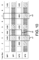
- FIG. 10 shows an example of the classification of time slots in the ABS patterns.
- each time slot in the ABS pattern may be categorized into a number of different classes.
- 3 rd time slot both the first macrocell ABS pattern MP1 and the second macrocell ABS pattern MP2 are ABS, both the small cells 11 and 21 may choose this time slot for data transmission.
- interference happens if these two cells both transmit data in the 3 rd time slot.
- Coordination is needed to determine which small cell transmits data in this time slot.
- Class c1 represents a time slot in which exactly one of the two small cells 11 and 21 may transmit.
- the second macrocell ABS pattern MP2 is not an ABS, therefore the second macrocell 2 transmits data at the 4 th time slot. Because there is an overlapping area between the first small cell 11 and the second macrocell 2, the first small cell 11 cannot use the 4 th time slot for data transmission although the first macrocell ABS pattern MP1 is an ABS in the 4 th time slot.
- Class c2 represents a time slot which a small cell is forbidden to transmit data because of the interference from a neighboring macrocell.
- the second macrocell ABS pattern MP2 is an ABS while the first macrocell ABS pattern MP1 is not an ABS. Because there is no overlapping area between the first macrocell 1 and the second small cell 21, the second small cell 21 is free to choose this time slot. There will be no interference because the first small cell 11 does not transmit data and the first macrocell 1 does not interfere with the second small cell 21.
- Class c3 represents a time slot which a small cell is free to choose without causing interference.
- the first and second small cell ABS patterns SP1 and SP2 may be determined according to the interference relationship.
- the determination may be performed by the coordination unit 302.
- time slots belonging to the class c1 need to be coordinated, thus the coordination unit 302 may determine that the first small cell 11 may use the 3 rd time slot while the second small cell 21 is prevented from using the 3 rd time slot, or vice versa.
- the interference coordination method may include: identifying first free time slots for the first small cell 11, second free time slots for the second small cell 21 (free time slots correspond to the class c3), and contested time slots (contested time slots correspond to the class c1) according to the first macrocell ABS pattern MP1, the second macrocell ABS pattern MP2, and the interference relationship. Note that in the above described procedure, the first and second load information is not necessarily needed for the determination.
- the first and second load information may further be taken into consideration.
- the interference coordination method may further include: distributing the contested time slots for the first small cell 11 and the second small cell 21 according to the first load information, the second load information, the first free time slots, the second free time slots, and the contested time slots. For example, if a small cell has a heavier loading, such as serving more UEs, more time slots may be distributed to that small cell.
- the related parameters of the first small cell 11 and the second small cell 21 are shown in Table 1.
- the load parameters shown in Table 1 represent how many time slots are required for each small cell, which may correspond to the session loading required by its serving UEs.
- the interference coordination method provided in this disclosure may also be applicable to three or more small cells.
- the load ratio R may be in the form of LC(1):LC(2):LC(3) when there are three small cells.
- the network server in this disclosure acts as a mediator for multiple neighboring small cells to determine their ABS patterns.
- the network server may collect ABS pattern information from multiple macrocells, collect load information form multiple small cells, and obtain interference relationship between the macrocells and the small cells, in order to generate appropriate ABS patterns to avoid inter-cell interference.
Landscapes
- Engineering & Computer Science (AREA)
- Computer Networks & Wireless Communication (AREA)
- Signal Processing (AREA)
- Mobile Radio Communication Systems (AREA)
Abstract
Description
- The disclosure relates in general to a method for interference coordination, and more particularly to a method for interference coordination related to macrocells and a network server.
- With the growth of mobile communication, in order to provide in-building and outdoor wireless service, mobile operators use small cells to extend their service coverage and increase network capacity. Small cells may be radio access nodes, for example, having a range of 10 meters to 2 kilometers, as compared to a macrocell, for example, having a range of a few tens of kilometers. Examples of small cells include femtocells, picocells, and microcells. In 3rd Generation Partnership Project (3GPP) terminology, a Node B (NB) is a 3G macrocell, an eNode B (eNB) is a Long Term Evolution (LTE) macrocell, a Home Node B (HNB) is a 3G femtocell, and a Home eNode B (HeNB) is a LTE femtocell.
- As wireless networks become increasingly dense to accommodate the rising traffic demand, inter-cell interference becomes one of the critical issues. Specifically, with an increasing number of small cells, deployment of small cells becomes denser and thus the distance between small cells becomes shorter. A user equipment (UE), such as a mobile phone, served by a serving cell may suffer from interference caused by a neighboring small cell. For example, when UE is near boundary of the serving cell, signal from neighboring cell acts as interferer. The Signal-to-Noise ratio (SNR) may be poor not only because of the weak signal strength from the serving cell but also because of the interference. Thus, there is a need for a method for
- The disclosure is directed to a method for interference coordination, a network server and a communication system using the same.
- According to one embodiment, a method for interference coordination is provided. The method includes: receiving a first macrocell almost blank subframe (ABS) pattern from a first macrocell, receiving a second macrocell ABS pattern from a second macrocell, determining a first small cell ABS pattern for a first small cell according to the first macrocell ABS pattern and the second macrocell ABS pattern, and transmitting the first small cell ABS pattern to the first small cell. The first small cell is within a coverage of the first macrocell.
- According to another embodiment, a network server is provided. The network server includes an ABS pattern management unit and a coordination unit. The ABS pattern management unit is configured to receive a first macrocell ABS pattern from a first macrocell, receive a second macrocell ABS pattern from a second macrocell, and transmit a first small cell ABS pattern to a first small cell. The coordination unit is configured to determine the first small cell ABS pattern for the first small cell according to the first macrocell ABS pattern and the second macrocell ABS pattern. The first small cell is within a coverage of the first macrocell.
- According to still another embodiment, a communication system is provided. The communication system includes a network server, a first macrocell, a second macrocell, and a first small cell. The first macrocell is connected to the network server and is configured to transmit a first macrocell ABS pattern to the network server. The second macrocell is connected to the network server and is configured to transmit a second macrocell ABS pattern to the network server. The first small cell is connected to the network server and is within a coverage of the first macrocell. The network server is configured to determine a first small cell ABS pattern for the first small cell according to the first macrocell ABS pattern and the second macrocell ABS pattern, and transmit the first small cell ABS pattern to the first small cell.
-
-
FIG. 1 shows an example of interference between two neighboring small cells. -
FIG. 2 shows a communication system according to an embodiment of this disclosure. -
FIG. 3 shows a block diagram illustrating a network server according to an embodiment of this disclosure. -
FIG. 4 shows a flowchart illustrating an interference coordination method according to an embodiment of this disclosure. -
FIG. 5 shows a diagram illustrating a process of interference coordination according to an embodiment of this disclosure. -
FIG. 6 shows a diagram illustrating a process of interference coordination according to an embodiment of this disclosure. -
FIG. 7 shows a block diagram illustrating a network server according to an embodiment of this disclosure. -
FIG. 8 shows a flowchart illustrating an interference coordination method according to an embodiment of this disclosure. -
FIG. 9 shows multiple scenarios regarding different interference relationships between macrocells and small cells. -
FIG. 10 shows an example of the classification of time slots in the ABS patterns. - In the following detailed description, for purposes of explanation, numerous specific details are set forth in order to provide a thorough understanding of the disclosed embodiments. It will be apparent, however, that one or more embodiments may be practiced without these specific details. In other instances, well-known structures and devices are schematically shown in order to simplify the drawing.
- In a heterogeneous network (HetNet) where a macrocell and a small cell coexist, a UE located near the boundary of the coverage of a small cell may suffer from interference induced from the macrocell. 3GPP has proposed enhanced inter-cell interference coordination (elCIC) to deal with this problem. An almost blank subframe (ABS) is used in elCIC to prevent the small cell from transmitting data at the same time as the serving macrocell. UEs connected to the small cell can thus receive data during such ABS to avoid interference from the macrocell. For example, the macrocell may inform the small cell an ABS pattern to let the small cell know which time slots are available for data transmission. The macrocell serves as the control center to determine an ABS pattern for the small cells in its coverage area to prevent interference. However, there may still be inter-cell interference when two neighboring macrocells use different ABS patterns.
-
FIG. 1 shows an example of interference between two neighboring small cells. In this example,small cell 11 andsmall cell 12 are in the coverage of themacrocell 1.Small cell 21 andsmall cell 22 are in the coverage of themacrocell 2. The coverage of a cell in this disclosure may be the area where received pilot signal strength from this cell is higher than a sensitive threshold of a mobile device. Themacrocell 1 sets the ABS pattern as {111110000} for thesmall cells 11 and 12 (the '1' in the ABS pattern represents an ABS in which the small cell can transmit data). Themacrocell 2 sets the ABS pattern as {110011001} for thesmall cells small cell 11 and thesmall cell 21 may transmit data simultaneously in the 1st, 2nd, and 5th subframe. Therefore a UE in the intersection of the coverage areas of thesmall cells -
FIG. 2 shows acommunication system 9 according to an embodiment of this disclosure. Thecommunication system 9 includes anetwork server 3,macrocells small cells communication system 9. Thenetwork server 3 may be connected to themacrocells network server 3 may also be connected to thesmall cells - For example, the
network server 3 may be a self-organizing network (SON) server. A SON is an automation technology designed to make the planning, configuration, management, optimization and healing of mobile radio access networks simpler and faster. Thenetwork server 3 acts as a mediator between themacrocells small cells network server 3 is able to integrate different ABS patterns information from themacrocells small cells -
FIG. 3 shows a block diagram illustrating anetwork server 3 according to an embodiment of this disclosure. Referring toFIG. 2 andFIG. 3 , thenetwork server 3 includes an ABSpattern management unit 300 and acoordination unit 302. The ABSpattern management unit 300 is configured to receive a first macrocell ABS pattern MP1 from afirst macrocell 1, receive a second macrocell ABS pattern MP2 from asecond macrocell 2, and transmit a first small cell ABS pattern SP1 to a firstsmall cell 11. Thecoordination unit 302 is configured to determine the first small cell ABS pattern SP1 for the firstsmall cell 11 according to the first macrocell ABS pattern MP1 and the second macrocell ABS pattern MP2. The ABSpattern management unit 300 and thecoordination unit 302 may be implemented by software, firmware, or hardware. For example, the ABSpattern management unit 300 and thecoordination unit 302 may be functional modules in a software program. The software program may be loaded from a memory device and executed by a processor. Alternatively the ABSpattern management unit 300 and thecoordination unit 302 may also be circuit blocks with the corresponding functions, such as application specific integrated circuits. - Also refer to
FIG. 4 , which shows a flowchart illustrating an interference coordination method according to an embodiment of this disclosure. Referring toFIG. 2 ,FIG. 3 , andFIG. 4 , the flowchart may correspond to the steps performed by thenetwork server 3. The interference coordination method includes the following steps: Step S201 receiving a first macrocell ABS pattern MP1 from afirst macrocell 1. Step S202 receiving a second macrocell ABS pattern MP2 from asecond macrocell 2. Step S211 determining a first small cell ABS pattern SP1 for a firstsmall cell 11 according to the first macrocell ABS pattern MP1 and the second macrocell ABS pattern MP2. Step S213 transmitting the first small cell ABS pattern SP1 to the firstsmall cell 11. In one embodiment, the steps S201, S202, and S213 may be performed by the ABSpattern management unit 300, and the step S211 may be performed by thecoordination unit 302. It should be noted that the step order shown inFIG. 4 is just exemplary rather than limiting. - For a better understanding of the interference coordination method mentioned above,
FIG. 5 shows a diagram illustrating a process of interference coordination according to an embodiment of this disclosure. Numbers 1-7 shown in the circles represent the steps executed in sequence in this exemplary process. In the following description, these numbers will be represented as steps S1-S7. It should be noted that the step order shown inFIG. 5 is just exemplary rather than limiting. - Step S1: the first
small cell 11 transmits a first request Req1 for ABS pattern information to thenetwork server 3. For example, the firstsmall cell 11 may need to know what ABS pattern is available from its belongingfirst macrocell 1 in order to communicate with a UE with an appropriate ABS pattern. - Step S2: upon receiving the first request Req1 from the first
small cell 11, thenetwork server 3 transmits a second request Req2 for the ABS pattern information to thefirst macrocell 1 in response to the first request Req1. In other words, the firstsmall cell 11 does not send a request for the ABS pattern information directly to thefirst macrocell 1. Instead, thenetwork server 3 receives requests from the firstsmall cell 11 and transmits the requests to thefirst macrocell 1. In addition, thenetwork server 3 knows that the coverage of thefirst macrocell 1 overlaps the coverage of thesecond macrocell 2, and hence thenetwork server 3 may also transmit a request for the ABS pattern information to thesecond macrocell 2 in response to the first request Req1. Also note that the process performed in the steps S1 and S2 is not mandatory. For example, thefirst macrocell 1 and thesecond macrocell 2 may also actively (or periodically) transmit the ABS pattern without waiting for a request for the ABS pattern information. - Step S3: the
first macrocell 1 determines the first macrocell ABS pattern MP1 and then transmits the first macrocell ABS pattern MP1 to the network server 3 (corresponding to the step S201 inFIG. 4 ). Similarly, thesecond macrocell 2 determines the second macrocell ABS pattern MP2 and then transmits the second macrocell ABS pattern MP2 to the network server 3 (corresponding to the step S202 inFIG. 4 ). Themacrocells network server 3, such that the ABS patterns from the two macrocells are integrated. - Step S4: upon receiving the first macrocell ABS pattern MP1 and the second macrocell ABS pattern MP2, the
network server 3 determines a first small cell ABS pattern SP1 for the firstsmall cell 11 according to the first macrocell ABS pattern MP1 and the second macrocell ABS pattern MP2 (corresponding to the step S211 inFIG. 4 ). Because thenetwork server 3 now knows ABS pattern information in both the macrocells, thenetwork server 3 is able to determine ABS patterns for the small cells in respective macrocell's coverage in order to avoid inter-cell interference. There may be various ways for thenetwork server 3 to determine the first small cell ABS pattern SP1. Examples will be given in the following description. - Step S5: the
network server 3 transmits the first small cell ABS pattern SP1 to the first small cell 11 (corresponding to the step S213 inFIG. 4 ). The firstsmall cell 11 then knows which time slots are available for data transmission. Moreover, because the first small cell ABS pattern SP1 implicitly possesses interference avoidance information, a UE communicating with the firstsmall cell 11 will not be interfered by another neighboring small cell within the coverage of thesecond macrocell 2. - Step S6: the first
small cell 11 transmits a first selected ABS pattern CP1 to thenetwork server 3 in response to the first small cell ABS pattern SP1. In other words, the firstsmall cell 11 reports its usage information to thenetwork server 3. The first selected ABS pattern CP1 may include which time slots in the first small cell ABS pattern SP1 are chosen for data transmission by the firstsmall cell 11. For example, there may be three ABS in the first small cell ABS pattern SP1, and the firstsmall cell 11 may choose two out of the three ABS for data transmission. These two chosen ABS are reported in the first selected ABS pattern CP1. - Step S7: the
network server 3 transmits the first selected ABS pattern CP1 to thefirst macrocell 1 and/or thesecond macrocell 2. Therefore thefirst macrocell 1 and/or thesecond macrocell 2 know the actual ABS usage information of the firstsmall cell 11, for example, which time slots are occupied by the firstsmall cell 11. Thefirst macrocell 1 and/or thesecond macrocell 2 can then determine an updated ABS pattern for another small cell in their coverage areas. - In the above example, the
network server 3 serves as a communication bridge between thefirst macrocell 1 and the firstsmall cell 11, and also serves as a communication bridge between thesecond macrocell 2 and the firstsmall cell 11. Because the firstsmall cell 11 transmits request to thenetwork server 3 and receives ABS pattern from thenetwork server 3, thenetwork server 3 acts like a macrocell from the viewpoint of the firstsmall cell 11. On the other hand, because the first macrocell 1 (and the second macrocell 2) receives request from thenetwork server 3 and transmits ABS pattern to thenetwork server 3, thenetwork server 3 acts like a small cell from the viewpoint of the first macrocell 1 (and the second macrocell 2). Thenetwork server 3 thus emulates the functions of both a macrocell and a small cell. -
FIG. 6 shows a diagram illustrating a process of interference coordination according to an embodiment of this disclosure. The process is similar to that shown inFIG. 5 and the numbers in circles also represent the steps executed in sequence. The numbers inFIG. 6 will be represented as steps S8-S11 in the following description. Note that different numbers are used here to avoid confusion to those used inFIG. 5 . However, the numbers shown inFIG. 6 and the numbers shown inFIG. 5 do not indicate a strict step order. For example, the step S8 shown inFIG. 6 may also be performed before the step S1 shown inFIG. 5 . - In this embodiment, there are two
small cells small cell 11 is within the coverage of thefirst macrocell 1 and the secondsmall cell 21 is within the coverage of thesecond macrocell 2. The coverage of the firstsmall cell 11 overlaps the coverage of the secondsmall cell 21. Interference coordination may be needed for a UE located in the overlapped region between the firstsmall cell 11 and the secondsmall cell 21 to provide a better communication quality. Some additional steps are shown inFIG. 6 as compared toFIG. 5 . - Step S8: the second
small cell 21 transmits a third request Req3 for ABS pattern information to the network server 3 (similar to the step S1). Step S9: thenetwork server 3 determines a first small cell ABS pattern SP1 for the firstsmall cell 11 according to the first macrocell ABS pattern MP1 and the second macrocell ABS pattern MP2. Thenetwork server 3 transmits the first small cell ABS pattern SP1 to the firstsmall cell 11. In addition, thenetwork server 3 determines a second small cell ABS pattern SP2 for the secondsmall cell 21 according to the first macrocell ABS pattern MP1 and the second macrocell ABS pattern MP2. Thenetwork server 3 transmits the second small cell ABS pattern SP2 to the second small cell 21 (similar to the steps S4 and S5). Step S10: the firstsmall cell 11 transmits a first selected ABS pattern CP1 to thenetwork server 3 in response to the first small cell ABS pattern SP1, and the secondsmall cell 21 transmits a second selected ABS pattern CP2 to thenetwork server 3 in response to the second small cell ABS pattern SP2 (similar to the step S6). Step S11: thenetwork server 3 transmits the second selected ABS pattern CP2 and/or the first selected ABS pattern CP1 to thesecond macrocell 2 and/or the first macrocell 1 (similar to the step S7). - In this embodiment, because the
network server 3 has ABS pattern information from both thefirst macrocell 1 and thesecond macrocell 2, the first small cell ABS pattern SP1 thus determined would be consistent with the first macrocell ABS pattern MP1. Likewise, the second small cell ABS pattern SP2 would be consistent with the second macrocell ABS pattern MP2. Furthermore, thenetwork server 3 serves as a mediator between the firstsmall cell 11 and the secondsmall cell 21 to coordinate the inter-cell interference. By using the first small cell ABS pattern SP1 and the second small cell ABS pattern SP2, the firstsmall cell 11 and the secondsmall cell 21 that are close to each other may use different time slots for data transmission, thus the inter-cell interference would be prevented. - In the following is given a description of the determination of the first small cell ABS pattern SP1 and the second small cell ABS pattern SP2.
FIG. 7 shows a block diagram illustrating anetwork server 4 according to an embodiment of this disclosure. As compare to thenetwork server 3 shown inFIG. 3 , thenetwork server 4 further includes atopology management unit 304 and aload management unit 306. Thetopology management unit 304 and theload management unit 306 may also be implemented by software, firmware, or hardware. - Referring to
FIG. 5 ,FIG. 6 , andFIG. 7 , thetopology management unit 304 is configured to obtain interference relationship between thefirst macrocell 1, thesecond macrocell 2, the firstsmall cell 11 and the secondsmall cell 21. Thecoordination unit 302 determines the first small cell ABS pattern SP1 and the second small cell ABS pattern SP2 according to the interference relationship. The interference relationship may refer to whether or not the coverage of the individual cell overlaps with each other. - The
load management unit 306 is configured to receive a first load information from the firstsmall cell 11 and receive a second load information from the secondsmall cell 21. The first load information may include the number of serving UEs and the required bandwidth of the firstsmall cell 11. Refer toFIG. 5 , the first load information may be encompassed in the first request Req1 transmitted in the step S1. Thefirst macrocell 1 is then able to determine how many resources can be allocated to the firstsmall cell 11 depending on the first load information. Similarly, the second load information may include the number of serving UEs and the required bandwidth of the secondsmall cell 21. Refer toFIG. 6 , the second load information may be encompassed in the third request Req3 transmitted in the step S8. In addition, thecoordination unit 302 of thenetwork server 4 determines the first small cell ABS pattern SP1 and the second small cell ABS pattern SP2 according to the first load information and the second load information. - Also refer to
FIG. 8 , which shows a flowchart illustrating an interference coordination method according to an embodiment of this disclosure. The flowchart may correspond to the steps performed by thenetwork server 4 inFIG. 7 . Referring toFIG. 5 ,FIG. 6 ,FIG. 7 andFIG. 8 , the interference coordination method includes the following step: Step S201 receiving a first macrocell ABS pattern MP1 from afirst macrocell 1. Step S202 receiving a second macrocell ABS pattern MP2 from asecond macrocell 2. Step S204 obtaining interference relationship between thefirst macrocell 1, thesecond macrocell 2, the firstsmall cell 11, and the secondsmall cell 21. Step S205 receiving a first load information from the firstsmall cell 11. Step S206 receiving a second load information from the secondsmall cell 21. Step S221 determining the first small cell ABS pattern SP1 for the firstsmall cell 11 according to the interference relationship, the first load information, the second load information, the first macrocell ABS pattern MP1 and the second macrocell ABS pattern MP2. Step S223 transmitting the first small cell ABS pattern SP1 to the firstsmall cell 11. In one embodiment, Step S221 also determining the second small cell ABS pattern SP2 for the secondsmall cell 21 according to the interference relationship, the first load information, the second load information, the first macrocell ABS pattern MP1 and the second macrocell ABS pattern MP2. In one embodiment, the steps S201, S202, and S223 may be performed by the ABSpattern management unit 300, the steps S204 may be performed by thetopology management unit 304, the steps S205 and S206 may be performed by theload management unit 306, and the step S221 may be performed by thecoordination unit 302. It should be noted that the step order shown inFIG. 8 is just exemplary rather than limiting. - As described above, the interference relationship may refer to the overlapping between the coverage of each cell, which is related to the neighboring cells of each cell. Such neighbor cell information may be obtained in various ways. For example, when the cell (either a marcocell or a small cell) boots up, the cell may detect its neighboring cells. In addition, since UE detects all the cells around it, the cell may instruct UE to perform measurement and check the existence of neighboring cells. The cell then may extract the neighboring cell information from UE. Such procedure is, for example, the automatic neighbor relation (ANR) functionality defined in the 3GPP specification.
- The
topology management unit 304 inFIG. 7 may construct a graph or a topology corresponding to the obtained interference relationship.FIG. 9 shows multiple scenarios regarding different interference relationships between macrocells and small cells. A macrocell and a small cell are represented as nodes in the graph. The coverage of a macrocell is shown in dashed lines, while the coverage of a small cell is shown in solid lines inFIG. 9 . Four example topologies are shown inFIG. 9 corresponding to four different interference relationships. Scenario (a): the coverage of thefirst macrocell 1 overlaps both the coverage of the firstsmall cell 11 and the coverage of the secondsmall cell 21. The coverage of thesecond macrocell 2 also overlaps both the coverage of the firstsmall cell 11 and the coverage of the secondsmall cell 21. Scenario (b): the coverage of thefirst macrocell 1 overlaps the coverage of the firstsmall cell 11 but not the coverage of the secondsmall cell 21. The coverage of thesecond macrocell 2 overlaps the coverage of the secondsmall cell 21 but not the coverage of the firstsmall cell 11. Scenario (c): the coverage of thefirst macrocell 1 overlaps the coverage of the firstsmall cell 11 but not the coverage of the secondsmall cell 21. The coverage of thesecond macrocell 2 overlaps both the coverage of the firstsmall cell 11 and the coverage of the secondsmall cell 21. Scenario (d): the coverage of thefirst macrocell 1 overlaps both the coverage of the firstsmall cell 11 and the coverage of the secondsmall cell 21. The coverage of thesecond macrocell 2 overlaps the coverage of the secondsmall cell 21 but not the coverage of the firstsmall cell 11. In all of these four example scenarios, the coverage of the firstsmall cell 11 overlaps the coverage of the secondsmall cell 21. Based on the topology, thecoordination unit 302 determines how to assign appropriate ABS patterns to avoid interference caused by the overlapping areas shown in the graph. -
FIG. 10 shows an example of the classification of time slots in the ABS patterns. Take scenario (c) inFIG. 9 for example, each time slot in the ABS pattern may be categorized into a number of different classes. 3rd time slot: both the first macrocell ABS pattern MP1 and the second macrocell ABS pattern MP2 are ABS, both thesmall cells small cell 11 and the secondsmall cell 21, interference happens if these two cells both transmit data in the 3rd time slot. Coordination is needed to determine which small cell transmits data in this time slot. Class c1 represents a time slot in which exactly one of the twosmall cells - 4th time slot: the second macrocell ABS pattern MP2 is not an ABS, therefore the
second macrocell 2 transmits data at the 4th time slot. Because there is an overlapping area between the firstsmall cell 11 and thesecond macrocell 2, the firstsmall cell 11 cannot use the 4th time slot for data transmission although the first macrocell ABS pattern MP1 is an ABS in the 4th time slot. Class c2 represents a time slot which a small cell is forbidden to transmit data because of the interference from a neighboring macrocell. - 7th time slot: the second macrocell ABS pattern MP2 is an ABS while the first macrocell ABS pattern MP1 is not an ABS. Because there is no overlapping area between the
first macrocell 1 and the secondsmall cell 21, the secondsmall cell 21 is free to choose this time slot. There will be no interference because the firstsmall cell 11 does not transmit data and thefirst macrocell 1 does not interfere with the secondsmall cell 21. Class c3 represents a time slot which a small cell is free to choose without causing interference. - After the time slots have been classified, the first and second small cell ABS patterns SP1 and SP2 may be determined according to the interference relationship. The determination may be performed by the
coordination unit 302. In the above example, time slots belonging to the class c1 need to be coordinated, thus thecoordination unit 302 may determine that the firstsmall cell 11 may use the 3rd time slot while the secondsmall cell 21 is prevented from using the 3rd time slot, or vice versa. - As described above, the interference coordination method may include: identifying first free time slots for the first
small cell 11, second free time slots for the second small cell 21 (free time slots correspond to the class c3), and contested time slots (contested time slots correspond to the class c1) according to the first macrocell ABS pattern MP1, the second macrocell ABS pattern MP2, and the interference relationship. Note that in the above described procedure, the first and second load information is not necessarily needed for the determination. - In one embodiment, the first and second load information may further be taken into consideration. The interference coordination method may further include: distributing the contested time slots for the first
small cell 11 and the secondsmall cell 21 according to the first load information, the second load information, the first free time slots, the second free time slots, and the contested time slots. For example, if a small cell has a heavier loading, such as serving more UEs, more time slots may be distributed to that small cell. - One exemplary procedure regarding the distribution of the contested time slots may be expressed as (the symbol # will be used to represent the meaning of "the number of" in the following description):
- 1. Calculate the required number of iterations.
Iteration N = (total load amount) / (# usable ABS)
usable ABS means time slots belonging to class c1 orc3 2. - Calculate the load amount that needs coordination for each small cell.
load amount needing coordination for cell i LC(i) = Load(i) - (# class c3 slots)*N
Load(i) means the load of the small cell i - 3. Distribute contested time slots according to the load ratio.
load ratio R = LC(1)/LC(2) - One example is given below. The related parameters of the first
small cell 11 and the secondsmall cell 21 are shown in Table 1. The load parameters shown in Table 1 represent how many time slots are required for each small cell, which may correspond to the session loading required by its serving UEs. According to the above procedure, iteration N = (total load amount) / (# usable ABS) = (40+80)/(1+2+3) = 20. The load amount that needs coordination for the firstsmall cell 11 LC(11) = Load(11) - (# class c3 slots)*N = 40 - 1*20 = 20. The load amount that needs coordination for the secondsmall cell 21 LC(21) = Load(21)- (# class c3 slots)*N = 80 - 2*20 = 40. Load ratio R = LC(11)/LC(21) = 20/40 = 1/2. Because the number of contested time slots (class c1) in each iteration is equal to 3, the firstsmall cell 11 can use 1 time slot and the secondsmall cell 21 can use 2 time slots according to the load ratio R.Table 1 Load # ABS that can be freely chosen (class c3) # ABS that need coordination (class c1) First small cell 1140 1 3 Second small cell 2180 2 - Two small cells are taken for example in the above procedure. However, the interference coordination method provided in this disclosure may also be applicable to three or more small cells. For example, the load ratio R may be in the form of LC(1):LC(2):LC(3) when there are three small cells. In summary, the network server in this disclosure acts as a mediator for multiple neighboring small cells to determine their ABS patterns. In addition, the network server may collect ABS pattern information from multiple macrocells, collect load information form multiple small cells, and obtain interference relationship between the macrocells and the small cells, in order to generate appropriate ABS patterns to avoid inter-cell interference.
- It will be apparent to those skilled in the art that various modifications and variations can be made to the disclosed embodiments. It is intended that the specification and examples be considered as exemplary only, with a true scope of the disclosure being indicated by the following claims and their equivalents.
Claims (15)
- A method for interference coordination, characterized in that the method comprises:(S201) receiving a first macrocell almost blank subframe (ABS) pattern from a first macrocell (1);(S202) receiving a second macrocell ABS pattern from a second macrocell (2);(S211) determining a first small cell ABS pattern for a first small cell (11) according to the first macrocell ABS pattern and the second macrocell ABS pattern; and(S213) transmitting the first small cell ABS pattern to the first small cell (11);wherein the first small cell (11) is within a coverage of the first macrocell (1).
- The method according to claim 1, characterized in that the method further comprises:determining a second small cell ABS pattern for a second small cell (21) according to the first macrocell ABS pattern and the second macrocell ABS pattern; andtransmitting the second small cell ABS pattern to the second small cell (21);wherein the second small cell (21) is within a coverage of the second macrocell (2), and a coverage of the first small cell (11) overlaps a coverage of the second small cell (21).
- The method according to claim 2, characterized in that the method further comprises:(S204) obtaining interference relationship between the first macrocell (1), the second macrocell (2), the first small cell (11), and the second small cell (21);(S205) receiving a first load information from the first small cell (11); and(S206) receiving a second load information from the second small cell (21);wherein the first small cell ABS pattern and the second small cell ABS pattern are determined according to the interference relationship, the first load information and the second load information.
- The method according to claim 3, characterized in that the method further comprises:identifying first free time slots for the first small cell (11), second free time slots for the second small cell (21), and contested time slots according to the first macrocell ABS pattern, the second macrocell ABS pattern, and the interference relationship; anddistributing the contested time slots for the first small cell (11) and the second small cell (21) according to the first load information, the second load information, the first free time slots, the second free time slots, and the contested time slots.
- The method according to any one of the claims 1 to 4, characterized in that the method further comprises:receiving a first selected ABS pattern generated by the first small cell (11) in response to the first small cell ABS pattern;transmitting the first selected ABS pattern to at least one of the first macrocell (1) and the second macrocell (2);receiving a first request for ABS pattern information from the first small cell (11); andtransmitting a second request for the ABS pattern information to the first macrocell (1) in response to the first request.
- A network server (3, 4), characterized in that the network server comprises:an almost blank subframe (ABS) pattern management unit (300), configured to receive a first macrocell ABS pattern from a first macrocell (1), receive a second macrocell ABS pattern from a second macrocell (2), and transmit a first small cell ABS pattern to a first small cell (11); anda coordination unit (302), configured to determine the first small cell ABS pattern for the first small cell (11) according to the first macrocell ABS pattern and the second macrocell ABS pattern;wherein the first small cell (11) is within a coverage of the first macrocell (1).
- The network server (3, 4) according to claim 6, characterized in that
the coordination unit (302) is further configured to determine a second small cell ABS pattern for a second small cell (21) according to the first macrocell ABS pattern and the second macrocell ABS pattern; and
the ABS pattern management unit (300) is further configured to transmit the second small cell ABS pattern to the second small cell (21), the second small cell (21) being within a coverage of the second macrocell (2);
wherein a coverage of the first small cell (11) overlaps a coverage of the second small cell (21). - The network server (3, 4) according to claim 7, characterized in that the network server (3, 4) further comprises:a topology management unit (304), configured to obtain interference relationship between the first macrocell (1), the second macrocell (2), the first small cell (11), and the second small cell (21); anda load management unit (306), configured to receive a first load information from the first small cell (11) and receive a second load information from the second small cell (21);wherein the coordination unit (302) determines the first small cell ABS pattern and the second small cell ABS pattern according to the interference relationship, the first load information and the second load information.
- The network server (3, 4) according to claim 8, characterized in that the coordination unit (302) is further configured to
identify first free time slots for the first small cell (11), second free time slots for the second small cell (21), and contested time slots according to the first macrocell ABS pattern, the second macrocell ABS pattern, and the interference relationship, and
distribute the contested time slots for the first small cell (11) and the second small cell (21) according to the first load information, the second load information, the first free time slots, the second free time slots, and the contested time slots. - The network server (3, 4) according to any one of the claims 6 to 9, characterized in that the ABS pattern management unit (300) is further configured to
receive a first selected ABS pattern generated by the first small cell (11) in response to the first small cell ABS pattern,
transmit the first selected ABS pattern to at least one of the first macrocell (1) and the second macrocell (2),
receive a first request for ABS pattern information from the first small cell (11), and
transmit a second request for the ABS pattern information to the first macrocell (1) in response to the first request. - A communication system (9), characterized in that the communication system (9) comprises:a network server (3, 4);a first macrocell (1), connected to the network server (3), configured to transmit a first macrocell almost blank subframe (ABS) pattern to the network server (3, 4);a second macrocell (2), connected to the network server (3, 4), configured to transmit a second macrocell ABS pattern to the network server (3, 4); anda first small cell (11), connected to the network server (3), and being within a coverage of the first macrocell (1);wherein the network server (3, 4) is configured to determine a first small cell ABS pattern for the first small cell (11) according to the first macrocell ABS pattern and the second macrocell ABS pattern, and transmit the first small cell ABS pattern to the first small cell (11).
- The communication system (9) according to claim 11, characterized in that the communication system (9) further comprises:a second small cell (21), connected to the network server (3), and being within a coverage of the second macrocell (2);wherein a coverage of the first small cell (11) overlaps a coverage of the second small cell (21), the network server (3, 4) is further configured to determine a second small cell ABS pattern for the second small cell (21) according to the first macrocell ABS pattern and the second macrocell ABS pattern, and transmit the second small cell ABS pattern to the second small cell (21).
- The communication system (9) according to claim 12, characterized in that
the network server (3, 4) is further configured to obtain interference relationship between the first macrocell (1), the second macrocell (2), the first small cell (11), and the second small cell (21);
the first small cell (11) transmits a first load information to the network server (3, 4);
the second small cell (21) transmits a second load information to the network server (3, 4); and
the network server (3, 4) determines the first small cell ABS pattern and the second small cell ABS pattern according to the interference relationship, the first load information and the second load information. - The communication system (9) according to claim 13, characterized in that the network server (3, 4) is further configured to
identify first free time slots for the first small cell (11), second free time slots for the second small cell (21), and contested time slots according to the first macrocell ABS pattern, the second macrocell ABS pattern, and the interference relationship, and
distribute the contested time slots for the first small cell (11) and the second small cell (21) according to the first load information, the second load information, the first free time slots, the second free time slots, and the contested time slots. - The communication system (9) according to any one of the claims 11 to 14, characterized in that
the first small cell (11) transmits a first selected ABS pattern to the network server (3, 4) in response to the first small cell ABS pattern;
the network server (3, 4) transmits the first selected ABS pattern to at least one of the first macrocell (1) and the second macrocell (2);
the first small cell (11) transmits a first request for ABS pattern information to the network server (3, 4); and
the network server (3, 4) transmits a second request for the ABS pattern information to the first macrocell (1) in response to the first request.
Applications Claiming Priority (1)
| Application Number | Priority Date | Filing Date | Title |
|---|---|---|---|
| US14/948,236 US10028273B2 (en) | 2015-11-20 | 2015-11-20 | Method for interference coordination, network server and communication system using the same |
Publications (2)
| Publication Number | Publication Date |
|---|---|
| EP3171623A1 true EP3171623A1 (en) | 2017-05-24 |
| EP3171623B1 EP3171623B1 (en) | 2021-02-24 |
Family
ID=55079954
Family Applications (1)
| Application Number | Title | Priority Date | Filing Date |
|---|---|---|---|
| EP15201567.3A Active EP3171623B1 (en) | 2015-11-20 | 2015-12-21 | Method for interference coordination, network server and communication system using the same |
Country Status (4)
| Country | Link |
|---|---|
| US (1) | US10028273B2 (en) |
| EP (1) | EP3171623B1 (en) |
| CN (1) | CN106788857B (en) |
| TW (1) | TWI611719B (en) |
Families Citing this family (4)
| Publication number | Priority date | Publication date | Assignee | Title |
|---|---|---|---|---|
| KR102301826B1 (en) * | 2014-08-27 | 2021-09-14 | 삼성전자 주식회사 | Wireless communication system and method for managing resource for interference coordication thereof |
| TWI641279B (en) * | 2017-12-15 | 2018-11-11 | 財團法人工業技術研究院 | Mobile edge platform servers and user equipment context migration management methods thereof |
| TWI705669B (en) * | 2018-12-24 | 2020-09-21 | 財團法人工業技術研究院 | Apparatus and method for coordinating inter-cell interference and non-volatile computer readable media thereof |
| TWM614614U (en) * | 2021-01-21 | 2021-07-21 | 加拿大商 維喜鞋業有限公司 | Moisture-permeable and waterproof shoes with changeable upper appearance |
Citations (4)
| Publication number | Priority date | Publication date | Assignee | Title |
|---|---|---|---|---|
| US20130084865A1 (en) * | 2011-09-29 | 2013-04-04 | Nokia Siemens Networks Oy | Methods And Apparatus For Interference Management |
| US20140094181A1 (en) * | 2012-10-01 | 2014-04-03 | Nokia Siemens Networks Oy | Enhanced Metrics Exchange for a Wireless Network |
| US20150131553A1 (en) * | 2012-05-09 | 2015-05-14 | Telefonaktiebolaget L M Ericsson (Publ) | Radio base station |
| US20150207596A1 (en) * | 2012-09-13 | 2015-07-23 | Nokia Solutions And Networks Oy | Fast Load Balancing by Cooperative Scheduling for Heterogeneous Networks with eICIC |
Family Cites Families (17)
| Publication number | Priority date | Publication date | Assignee | Title |
|---|---|---|---|---|
| DE69739958D1 (en) | 1997-06-16 | 2010-09-23 | Mitsubishi Electric Corp | MOBILE COMMUNICATION SYSTEM |
| US8682313B2 (en) | 2009-12-08 | 2014-03-25 | Electronics And Telecommunications Research Institute | Over-the-air inter-cell interference coordination methods in cellular systems |
| KR20120049449A (en) | 2010-11-08 | 2012-05-17 | 삼성전자주식회사 | Wireless communication system and method for managing resource for inter-cell interference coordication thereof |
| US20130279419A1 (en) * | 2011-02-10 | 2013-10-24 | Panasonic Corporation | Base station device and transmitting method |
| CN102186247B (en) | 2011-05-05 | 2013-12-11 | 新邮通信设备有限公司 | Method and system for coordinating interference between cells |
| US9060377B2 (en) | 2011-11-02 | 2015-06-16 | Hitachi, Ltd. | ABS-based method for inter cell interference coordination in LTE-advanced networks |
| US20140378135A1 (en) | 2012-01-30 | 2014-12-25 | Panasonic Corporation | Management server, mobile base station and wireless communication system |
| US8798021B2 (en) | 2012-03-16 | 2014-08-05 | Nokia Siemens Networks Oy | Hierarchical network and interference management |
| US8838127B2 (en) | 2012-05-11 | 2014-09-16 | Industrial Technology Research Institute | Interference mitigation method in cellular wireless network, and apparatus with the same |
| US8838125B2 (en) | 2012-06-29 | 2014-09-16 | Nokia Corporation | Interferer activity signaling for time domain (TDM) inter-cell interference coordination (ICIC) |
| US9106358B2 (en) | 2012-12-18 | 2015-08-11 | Airhop Communications, Inc. | Multi-cell interference management |
| WO2014138440A1 (en) | 2013-03-06 | 2014-09-12 | Interdigital Patent Holdings, Inc,. | Interference management and interference alignment in wireless networks including small base stations |
| CN104066093B (en) | 2013-03-18 | 2018-03-23 | 财团法人工业技术研究院 | Interference management method, anchor point equipment, base station and system of wireless communication system |
| CN105165089B (en) | 2013-03-20 | 2020-07-03 | 绍兴市寅川软件开发有限公司 | Method for coordinating uplink resource allocation |
| EP2833661B1 (en) * | 2013-07-31 | 2016-07-13 | Fujitsu Limited | A method for limiting inter-cell interference and load balancing and a wireless communication system and base station |
| CN104519586A (en) | 2013-10-04 | 2015-04-15 | 数码士控股有限公司 | Method for avoiding small cell interference during connection of plural LTE base stations |
| US9288804B2 (en) | 2014-04-25 | 2016-03-15 | Cisco Technology, Inc. | Almost blank subframe based orthogonal resource allocation in a wireless network environment |
-
2015
- 2015-11-20 US US14/948,236 patent/US10028273B2/en active Active
- 2015-12-15 TW TW104142153A patent/TWI611719B/en active
- 2015-12-21 EP EP15201567.3A patent/EP3171623B1/en active Active
- 2015-12-25 CN CN201510995556.3A patent/CN106788857B/en active Active
Patent Citations (4)
| Publication number | Priority date | Publication date | Assignee | Title |
|---|---|---|---|---|
| US20130084865A1 (en) * | 2011-09-29 | 2013-04-04 | Nokia Siemens Networks Oy | Methods And Apparatus For Interference Management |
| US20150131553A1 (en) * | 2012-05-09 | 2015-05-14 | Telefonaktiebolaget L M Ericsson (Publ) | Radio base station |
| US20150207596A1 (en) * | 2012-09-13 | 2015-07-23 | Nokia Solutions And Networks Oy | Fast Load Balancing by Cooperative Scheduling for Heterogeneous Networks with eICIC |
| US20140094181A1 (en) * | 2012-10-01 | 2014-04-03 | Nokia Siemens Networks Oy | Enhanced Metrics Exchange for a Wireless Network |
Also Published As
| Publication number | Publication date |
|---|---|
| CN106788857B (en) | 2019-04-05 |
| CN106788857A (en) | 2017-05-31 |
| TWI611719B (en) | 2018-01-11 |
| US10028273B2 (en) | 2018-07-17 |
| TW201720217A (en) | 2017-06-01 |
| EP3171623B1 (en) | 2021-02-24 |
| US20170150498A1 (en) | 2017-05-25 |
Similar Documents
| Publication | Publication Date | Title |
|---|---|---|
| JP6796724B2 (en) | Cumulative interference allocation | |
| CN110351807B (en) | Access selection method and device | |
| CN102036295B (en) | Method, system and equipment for determining uplink and downlink configuration | |
| US10057034B2 (en) | Method and system for dynamic allocation of resources in a cellular network | |
| Perez-Romero et al. | On the use of radio environment maps for interference management in heterogeneous networks | |
| US9537624B2 (en) | Fast load balancing by cooperative scheduling for heterogeneous networks with eICIC | |
| US9001789B2 (en) | Communication system, identifier assignment device, base station, identifier assignment method, and non-transitory computer readable medium embodying instructions for controlling a device | |
| US20150245221A1 (en) | Pci partition and allocation for cellular network | |
| US20160021585A1 (en) | Avoiding Secondary Cell Configuration for High Speed User Equipment | |
| KR20210045445A (en) | Measurement gap management for RRM measurement based on SSB and CSI-RS | |
| EP3171623B1 (en) | Method for interference coordination, network server and communication system using the same | |
| JP5935197B2 (en) | Method and apparatus for determining transmit power | |
| EP2856817B1 (en) | Control of carrier aggregation | |
| US11968143B2 (en) | Assignment of physical resource blocks to base stations | |
| CN107925923B (en) | Serving cell management | |
| US20170104572A1 (en) | Method for interference mitigation, network server and base station using the same | |
| US9071973B2 (en) | Communication network and method | |
| EP2999255B1 (en) | Inter-operator radio resource sharing in dense deployments of small cell networks | |
| WO2014169945A1 (en) | Physical cell identifier allocation | |
| US20160373203A1 (en) | Method for distributed interference coordination and small cell using the same | |
| CN113892301B (en) | Communication method and device | |
| JP2011176815A (en) | Method and device for determining which resource has to be allocated to home base station, and computer program | |
| WO2011134517A1 (en) | Interference management |
Legal Events
| Date | Code | Title | Description |
|---|---|---|---|
| PUAI | Public reference made under article 153(3) epc to a published international application that has entered the european phase |
Free format text: ORIGINAL CODE: 0009012 |
|
| STAA | Information on the status of an ep patent application or granted ep patent |
Free format text: STATUS: THE APPLICATION HAS BEEN PUBLISHED |
|
| AK | Designated contracting states |
Kind code of ref document: A1 Designated state(s): AL AT BE BG CH CY CZ DE DK EE ES FI FR GB GR HR HU IE IS IT LI LT LU LV MC MK MT NL NO PL PT RO RS SE SI SK SM TR |
|
| AX | Request for extension of the european patent |
Extension state: BA ME |
|
| STAA | Information on the status of an ep patent application or granted ep patent |
Free format text: STATUS: REQUEST FOR EXAMINATION WAS MADE |
|
| 17P | Request for examination filed |
Effective date: 20171123 |
|
| RBV | Designated contracting states (corrected) |
Designated state(s): AL AT BE BG CH CY CZ DE DK EE ES FI FR GB GR HR HU IE IS IT LI LT LU LV MC MK MT NL NO PL PT RO RS SE SI SK SM TR |
|
| STAA | Information on the status of an ep patent application or granted ep patent |
Free format text: STATUS: EXAMINATION IS IN PROGRESS |
|
| 17Q | First examination report despatched |
Effective date: 20190208 |
|
| RIC1 | Information provided on ipc code assigned before grant |
Ipc: H04W 16/10 20090101AFI20200917BHEP Ipc: H04W 16/32 20090101ALN20200917BHEP Ipc: H04W 72/04 20090101ALN20200917BHEP Ipc: H04W 84/04 20090101ALN20200917BHEP |
|
| GRAP | Despatch of communication of intention to grant a patent |
Free format text: ORIGINAL CODE: EPIDOSNIGR1 |
|
| STAA | Information on the status of an ep patent application or granted ep patent |
Free format text: STATUS: GRANT OF PATENT IS INTENDED |
|
| INTG | Intention to grant announced |
Effective date: 20201030 |
|
| RIN1 | Information on inventor provided before grant (corrected) |
Inventor name: SU, JUN-JIE Inventor name: HUANG, KUEI-LI Inventor name: WANG, CHUN-CHIEH |
|
| GRAS | Grant fee paid |
Free format text: ORIGINAL CODE: EPIDOSNIGR3 |
|
| GRAA | (expected) grant |
Free format text: ORIGINAL CODE: 0009210 |
|
| STAA | Information on the status of an ep patent application or granted ep patent |
Free format text: STATUS: THE PATENT HAS BEEN GRANTED |
|
| AK | Designated contracting states |
Kind code of ref document: B1 Designated state(s): AL AT BE BG CH CY CZ DE DK EE ES FI FR GB GR HR HU IE IS IT LI LT LU LV MC MK MT NL NO PL PT RO RS SE SI SK SM TR |
|
| REG | Reference to a national code |
Ref country code: GB Ref legal event code: FG4D |
|
| REG | Reference to a national code |
Ref country code: CH Ref legal event code: EP |
|
| REG | Reference to a national code |
Ref country code: DE Ref legal event code: R082 Ref document number: 602015065932 Country of ref document: DE Representative=s name: WR SERVICES GMBH, DE |
|
| REG | Reference to a national code |
Ref country code: DE Ref legal event code: R096 Ref document number: 602015065932 Country of ref document: DE |
|
| REG | Reference to a national code |
Ref country code: AT Ref legal event code: REF Ref document number: 1366014 Country of ref document: AT Kind code of ref document: T Effective date: 20210315 |
|
| REG | Reference to a national code |
Ref country code: IE Ref legal event code: FG4D |
|
| REG | Reference to a national code |
Ref country code: LT Ref legal event code: MG9D |
|
| REG | Reference to a national code |
Ref country code: NL Ref legal event code: MP Effective date: 20210224 |
|
| PG25 | Lapsed in a contracting state [announced via postgrant information from national office to epo] |
Ref country code: LT Free format text: LAPSE BECAUSE OF FAILURE TO SUBMIT A TRANSLATION OF THE DESCRIPTION OR TO PAY THE FEE WITHIN THE PRESCRIBED TIME-LIMIT Effective date: 20210224 Ref country code: PT Free format text: LAPSE BECAUSE OF FAILURE TO SUBMIT A TRANSLATION OF THE DESCRIPTION OR TO PAY THE FEE WITHIN THE PRESCRIBED TIME-LIMIT Effective date: 20210624 Ref country code: HR Free format text: LAPSE BECAUSE OF FAILURE TO SUBMIT A TRANSLATION OF THE DESCRIPTION OR TO PAY THE FEE WITHIN THE PRESCRIBED TIME-LIMIT Effective date: 20210224 Ref country code: FI Free format text: LAPSE BECAUSE OF FAILURE TO SUBMIT A TRANSLATION OF THE DESCRIPTION OR TO PAY THE FEE WITHIN THE PRESCRIBED TIME-LIMIT Effective date: 20210224 Ref country code: GR Free format text: LAPSE BECAUSE OF FAILURE TO SUBMIT A TRANSLATION OF THE DESCRIPTION OR TO PAY THE FEE WITHIN THE PRESCRIBED TIME-LIMIT Effective date: 20210525 Ref country code: BG Free format text: LAPSE BECAUSE OF FAILURE TO SUBMIT A TRANSLATION OF THE DESCRIPTION OR TO PAY THE FEE WITHIN THE PRESCRIBED TIME-LIMIT Effective date: 20210524 Ref country code: NO Free format text: LAPSE BECAUSE OF FAILURE TO SUBMIT A TRANSLATION OF THE DESCRIPTION OR TO PAY THE FEE WITHIN THE PRESCRIBED TIME-LIMIT Effective date: 20210524 |
|
| REG | Reference to a national code |
Ref country code: AT Ref legal event code: MK05 Ref document number: 1366014 Country of ref document: AT Kind code of ref document: T Effective date: 20210224 |
|
| PG25 | Lapsed in a contracting state [announced via postgrant information from national office to epo] |
Ref country code: NL Free format text: LAPSE BECAUSE OF FAILURE TO SUBMIT A TRANSLATION OF THE DESCRIPTION OR TO PAY THE FEE WITHIN THE PRESCRIBED TIME-LIMIT Effective date: 20210224 Ref country code: RS Free format text: LAPSE BECAUSE OF FAILURE TO SUBMIT A TRANSLATION OF THE DESCRIPTION OR TO PAY THE FEE WITHIN THE PRESCRIBED TIME-LIMIT Effective date: 20210224 Ref country code: LV Free format text: LAPSE BECAUSE OF FAILURE TO SUBMIT A TRANSLATION OF THE DESCRIPTION OR TO PAY THE FEE WITHIN THE PRESCRIBED TIME-LIMIT Effective date: 20210224 Ref country code: PL Free format text: LAPSE BECAUSE OF FAILURE TO SUBMIT A TRANSLATION OF THE DESCRIPTION OR TO PAY THE FEE WITHIN THE PRESCRIBED TIME-LIMIT Effective date: 20210224 Ref country code: SE Free format text: LAPSE BECAUSE OF FAILURE TO SUBMIT A TRANSLATION OF THE DESCRIPTION OR TO PAY THE FEE WITHIN THE PRESCRIBED TIME-LIMIT Effective date: 20210224 |
|
| PG25 | Lapsed in a contracting state [announced via postgrant information from national office to epo] |
Ref country code: IS Free format text: LAPSE BECAUSE OF FAILURE TO SUBMIT A TRANSLATION OF THE DESCRIPTION OR TO PAY THE FEE WITHIN THE PRESCRIBED TIME-LIMIT Effective date: 20210624 |
|
| PG25 | Lapsed in a contracting state [announced via postgrant information from national office to epo] |
Ref country code: SM Free format text: LAPSE BECAUSE OF FAILURE TO SUBMIT A TRANSLATION OF THE DESCRIPTION OR TO PAY THE FEE WITHIN THE PRESCRIBED TIME-LIMIT Effective date: 20210224 Ref country code: AT Free format text: LAPSE BECAUSE OF FAILURE TO SUBMIT A TRANSLATION OF THE DESCRIPTION OR TO PAY THE FEE WITHIN THE PRESCRIBED TIME-LIMIT Effective date: 20210224 Ref country code: CZ Free format text: LAPSE BECAUSE OF FAILURE TO SUBMIT A TRANSLATION OF THE DESCRIPTION OR TO PAY THE FEE WITHIN THE PRESCRIBED TIME-LIMIT Effective date: 20210224 Ref country code: EE Free format text: LAPSE BECAUSE OF FAILURE TO SUBMIT A TRANSLATION OF THE DESCRIPTION OR TO PAY THE FEE WITHIN THE PRESCRIBED TIME-LIMIT Effective date: 20210224 |
|
| REG | Reference to a national code |
Ref country code: DE Ref legal event code: R097 Ref document number: 602015065932 Country of ref document: DE |
|
| PG25 | Lapsed in a contracting state [announced via postgrant information from national office to epo] |
Ref country code: SK Free format text: LAPSE BECAUSE OF FAILURE TO SUBMIT A TRANSLATION OF THE DESCRIPTION OR TO PAY THE FEE WITHIN THE PRESCRIBED TIME-LIMIT Effective date: 20210224 Ref country code: RO Free format text: LAPSE BECAUSE OF FAILURE TO SUBMIT A TRANSLATION OF THE DESCRIPTION OR TO PAY THE FEE WITHIN THE PRESCRIBED TIME-LIMIT Effective date: 20210224 Ref country code: ES Free format text: LAPSE BECAUSE OF FAILURE TO SUBMIT A TRANSLATION OF THE DESCRIPTION OR TO PAY THE FEE WITHIN THE PRESCRIBED TIME-LIMIT Effective date: 20210224 Ref country code: DK Free format text: LAPSE BECAUSE OF FAILURE TO SUBMIT A TRANSLATION OF THE DESCRIPTION OR TO PAY THE FEE WITHIN THE PRESCRIBED TIME-LIMIT Effective date: 20210224 |
|
| PLBE | No opposition filed within time limit |
Free format text: ORIGINAL CODE: 0009261 |
|
| STAA | Information on the status of an ep patent application or granted ep patent |
Free format text: STATUS: NO OPPOSITION FILED WITHIN TIME LIMIT |
|
| PG25 | Lapsed in a contracting state [announced via postgrant information from national office to epo] |
Ref country code: AL Free format text: LAPSE BECAUSE OF FAILURE TO SUBMIT A TRANSLATION OF THE DESCRIPTION OR TO PAY THE FEE WITHIN THE PRESCRIBED TIME-LIMIT Effective date: 20210224 |
|
| 26N | No opposition filed |
Effective date: 20211125 |
|
| PG25 | Lapsed in a contracting state [announced via postgrant information from national office to epo] |
Ref country code: SI Free format text: LAPSE BECAUSE OF FAILURE TO SUBMIT A TRANSLATION OF THE DESCRIPTION OR TO PAY THE FEE WITHIN THE PRESCRIBED TIME-LIMIT Effective date: 20210224 |
|
| PG25 | Lapsed in a contracting state [announced via postgrant information from national office to epo] |
Ref country code: IT Free format text: LAPSE BECAUSE OF FAILURE TO SUBMIT A TRANSLATION OF THE DESCRIPTION OR TO PAY THE FEE WITHIN THE PRESCRIBED TIME-LIMIT Effective date: 20210224 |
|
| PG25 | Lapsed in a contracting state [announced via postgrant information from national office to epo] |
Ref country code: IS Free format text: LAPSE BECAUSE OF FAILURE TO SUBMIT A TRANSLATION OF THE DESCRIPTION OR TO PAY THE FEE WITHIN THE PRESCRIBED TIME-LIMIT Effective date: 20210624 |
|
| PG25 | Lapsed in a contracting state [announced via postgrant information from national office to epo] |
Ref country code: MC Free format text: LAPSE BECAUSE OF FAILURE TO SUBMIT A TRANSLATION OF THE DESCRIPTION OR TO PAY THE FEE WITHIN THE PRESCRIBED TIME-LIMIT Effective date: 20210224 |
|
| REG | Reference to a national code |
Ref country code: CH Ref legal event code: PL |
|
| REG | Reference to a national code |
Ref country code: BE Ref legal event code: MM Effective date: 20211231 |
|
| PG25 | Lapsed in a contracting state [announced via postgrant information from national office to epo] |
Ref country code: LU Free format text: LAPSE BECAUSE OF NON-PAYMENT OF DUE FEES Effective date: 20211221 Ref country code: IE Free format text: LAPSE BECAUSE OF NON-PAYMENT OF DUE FEES Effective date: 20211221 |
|
| PG25 | Lapsed in a contracting state [announced via postgrant information from national office to epo] |
Ref country code: BE Free format text: LAPSE BECAUSE OF NON-PAYMENT OF DUE FEES Effective date: 20211231 |
|
| PG25 | Lapsed in a contracting state [announced via postgrant information from national office to epo] |
Ref country code: LI Free format text: LAPSE BECAUSE OF NON-PAYMENT OF DUE FEES Effective date: 20211231 Ref country code: CH Free format text: LAPSE BECAUSE OF NON-PAYMENT OF DUE FEES Effective date: 20211231 |
|
| PG25 | Lapsed in a contracting state [announced via postgrant information from national office to epo] |
Ref country code: HU Free format text: LAPSE BECAUSE OF FAILURE TO SUBMIT A TRANSLATION OF THE DESCRIPTION OR TO PAY THE FEE WITHIN THE PRESCRIBED TIME-LIMIT; INVALID AB INITIO Effective date: 20151221 |
|
| PG25 | Lapsed in a contracting state [announced via postgrant information from national office to epo] |
Ref country code: CY Free format text: LAPSE BECAUSE OF FAILURE TO SUBMIT A TRANSLATION OF THE DESCRIPTION OR TO PAY THE FEE WITHIN THE PRESCRIBED TIME-LIMIT Effective date: 20210224 |
|
| PG25 | Lapsed in a contracting state [announced via postgrant information from national office to epo] |
Ref country code: MK Free format text: LAPSE BECAUSE OF FAILURE TO SUBMIT A TRANSLATION OF THE DESCRIPTION OR TO PAY THE FEE WITHIN THE PRESCRIBED TIME-LIMIT Effective date: 20210224 |
|
| PG25 | Lapsed in a contracting state [announced via postgrant information from national office to epo] |
Ref country code: TR Free format text: LAPSE BECAUSE OF FAILURE TO SUBMIT A TRANSLATION OF THE DESCRIPTION OR TO PAY THE FEE WITHIN THE PRESCRIBED TIME-LIMIT Effective date: 20210224 |
|
| PG25 | Lapsed in a contracting state [announced via postgrant information from national office to epo] |
Ref country code: MT Free format text: LAPSE BECAUSE OF FAILURE TO SUBMIT A TRANSLATION OF THE DESCRIPTION OR TO PAY THE FEE WITHIN THE PRESCRIBED TIME-LIMIT Effective date: 20210224 |
|
| PGFP | Annual fee paid to national office [announced via postgrant information from national office to epo] |
Ref country code: GB Payment date: 20251229 Year of fee payment: 11 |
|
| PGFP | Annual fee paid to national office [announced via postgrant information from national office to epo] |
Ref country code: FR Payment date: 20251226 Year of fee payment: 11 |
|
| PGFP | Annual fee paid to national office [announced via postgrant information from national office to epo] |
Ref country code: DE Payment date: 20251229 Year of fee payment: 11 |