EP3171494A1 - Permanent magnet rotor and method of making same - Google Patents
Permanent magnet rotor and method of making same Download PDFInfo
- Publication number
- EP3171494A1 EP3171494A1 EP16199320.9A EP16199320A EP3171494A1 EP 3171494 A1 EP3171494 A1 EP 3171494A1 EP 16199320 A EP16199320 A EP 16199320A EP 3171494 A1 EP3171494 A1 EP 3171494A1
- Authority
- EP
- European Patent Office
- Prior art keywords
- rotor core
- permanent magnets
- rotor
- fitting
- fixation sleeve
- Prior art date
- Legal status (The legal status is an assumption and is not a legal conclusion. Google has not performed a legal analysis and makes no representation as to the accuracy of the status listed.)
- Granted
Links
Images


Classifications
-
- H—ELECTRICITY
- H02—GENERATION; CONVERSION OR DISTRIBUTION OF ELECTRIC POWER
- H02K—DYNAMO-ELECTRIC MACHINES
- H02K1/00—Details of the magnetic circuit
- H02K1/06—Details of the magnetic circuit characterised by the shape, form or construction
- H02K1/22—Rotating parts of the magnetic circuit
- H02K1/27—Rotor cores with permanent magnets
- H02K1/2706—Inner rotors
- H02K1/272—Inner rotors the magnetisation axis of the magnets being perpendicular to the rotor axis
- H02K1/274—Inner rotors the magnetisation axis of the magnets being perpendicular to the rotor axis the rotor consisting of two or more circumferentially positioned magnets
- H02K1/2753—Inner rotors the magnetisation axis of the magnets being perpendicular to the rotor axis the rotor consisting of two or more circumferentially positioned magnets the rotor consisting of magnets or groups of magnets arranged with alternating polarity
- H02K1/278—Surface mounted magnets; Inset magnets
-
- H—ELECTRICITY
- H02—GENERATION; CONVERSION OR DISTRIBUTION OF ELECTRIC POWER
- H02K—DYNAMO-ELECTRIC MACHINES
- H02K1/00—Details of the magnetic circuit
- H02K1/06—Details of the magnetic circuit characterised by the shape, form or construction
- H02K1/22—Rotating parts of the magnetic circuit
- H02K1/27—Rotor cores with permanent magnets
- H02K1/2706—Inner rotors
- H02K1/272—Inner rotors the magnetisation axis of the magnets being perpendicular to the rotor axis
- H02K1/274—Inner rotors the magnetisation axis of the magnets being perpendicular to the rotor axis the rotor consisting of two or more circumferentially positioned magnets
-
- H—ELECTRICITY
- H02—GENERATION; CONVERSION OR DISTRIBUTION OF ELECTRIC POWER
- H02K—DYNAMO-ELECTRIC MACHINES
- H02K1/00—Details of the magnetic circuit
- H02K1/06—Details of the magnetic circuit characterised by the shape, form or construction
- H02K1/22—Rotating parts of the magnetic circuit
- H02K1/28—Means for mounting or fastening rotating magnetic parts on to, or to, the rotor structures
-
- H—ELECTRICITY
- H02—GENERATION; CONVERSION OR DISTRIBUTION OF ELECTRIC POWER
- H02K—DYNAMO-ELECTRIC MACHINES
- H02K15/00—Processes or apparatus specially adapted for manufacturing, assembling, maintaining or repairing of dynamo-electric machines
- H02K15/02—Processes or apparatus specially adapted for manufacturing, assembling, maintaining or repairing of dynamo-electric machines of stator or rotor bodies
- H02K15/03—Processes or apparatus specially adapted for manufacturing, assembling, maintaining or repairing of dynamo-electric machines of stator or rotor bodies having permanent magnets
-
- Y—GENERAL TAGGING OF NEW TECHNOLOGICAL DEVELOPMENTS; GENERAL TAGGING OF CROSS-SECTIONAL TECHNOLOGIES SPANNING OVER SEVERAL SECTIONS OF THE IPC; TECHNICAL SUBJECTS COVERED BY FORMER USPC CROSS-REFERENCE ART COLLECTIONS [XRACs] AND DIGESTS
- Y10—TECHNICAL SUBJECTS COVERED BY FORMER USPC
- Y10T—TECHNICAL SUBJECTS COVERED BY FORMER US CLASSIFICATION
- Y10T29/00—Metal working
- Y10T29/49—Method of mechanical manufacture
- Y10T29/49002—Electrical device making
- Y10T29/49009—Dynamoelectric machine
- Y10T29/49012—Rotor
Definitions
- the present disclosure relates generally to permanent magnet rotors of a type used in electrical machines, and relates more particularly to deforming material of a rotor core so as to bias permanent magnets positioned upon the rotor core against a fixation sleeve.
- Rotating components or "rotors" used in such electrical machines commonly employ a number of different parts.
- inertial forces can impart a tendency for rotor components to migrate from intended positions and potentially fail if unconstrained.
- simple component retention techniques such as adhesives can suffice.
- mechanical clamping components, retention sleeves and the like can be used.
- Known strategies have certain shortcomings in at least certain applications.
- making a permanent magnet rotor includes positioning a fixation sleeve about a rotor core having a plurality of permanent magnets.
- a plurality of pressure tools are then fitted into bores extending through a rotor core of the assembly, to deform material of the rotor core. Deformation of the material urges the magnets in a radially outward direction against the fixation sleeve to bias the magnets against the fixation sleeve.
- Machine system 10 may include a housing 12 wherein a stator 14 is positioned.
- a rotor 16 is positionable within housing 12 and rotatable to generate electrical current in windings of stator 14, or potentially induced to rotate by way of electrical current supplied to stator 14 from an electrical power source such as an electrical power grid.
- rotor 16 may be a relatively high speed rotor commonly having a speed range up to about 200 meters per second at its outermost surfaces, or potentially still greater.
- Those skilled in the art will be familiar with the relatively high inertial forces at relatively high speeds of rotor rotation.
- rotors according to the present disclosure are uniquely configured for maintaining structural integrity even at high rotational speeds.
- Rotor 16 includes a rotor core 18 defining a longitudinal axis 19, and a rotor core outer surface 20 that extends axially between a first shaft end 21 and a second shaft end 23.
- Shaft ends 21 and 23 could be structures formed integrally with rotor core 18, but can also be separate pieces attached to rotor core 18 such as by welding.
- Outer surface 20 may have a non-uniform contour, defining various features employed in mounting and retaining other components of rotor 16 as further discussed herein.
- Rotor core 18 further includes a plurality of bores 22 extending therethrough.
- a plurality of permanent magnets 24 are mounted upon rotor core outer surface 20.
- An end cap 28 and a second end cap 30 are positioned at opposite axial ends of a plurality of longitudinal rows of permanent magnets 24 in a practical implementation strategy.
- Spacers 32 and 34 may be positioned axially between adjacent permanent magnets 24 upon outer surface 20.
- a plurality of magnet retention elements 36 in the form of elongate rods may be positioned within grooves 38 formed by outer surface 20.
- elements 36 have a cross section generally similar to an hourglass, although no particular geometry is required. In some embodiments, devices to cancel or suppress eddy currents might also be used in rotor 16.
- Rotor 16 may further include a fixation sleeve 26 positioned about rotor core 18 and magnets 24, such that magnets 24 are in contact with fixation sleeve 26.
- sleeve 26 is shown partially in cutaway to illustrate additional features of rotor 16, however, it will be appreciated that sleeve 26 will typically extend axially at least as long as necessary to cover and constrain all of the magnets 24 and their associated mounting, retention and positioning hardware.
- Rotor 16 also includes a plurality of pressure tools 40 fitted within bores 22 such as by interference fitting, and deforming material of rotor core 18 such that the plurality of permanent magnets 24 are urged radially outwardly and biased by way of the deformation against fixation sleeve 26.
- pressure tools will typically remain resident within rotor core 18, in other embodiments they might serve the purposes of material deformation and biasing, and then be removed. Pressure tools 40 might or might not have shapes complementary to shapes of bores 22, and pressure tools 40 could themselves be deformed by way of the interference fitting.
- magnets 24 may be positioned in a plurality of longitudinal rows at a plurality of circumferential locations about longitudinal rotor axis 19.
- Grooves 38 may be positioned in an alternating arrangement with the plurality of longitudinal rows of magnets 24. It can also be seen from Figure 1 and figures attached but yet to be described that magnet retention rods 36 may be shaped so as to circumferentially overlap edges of each of magnets 24 in adjacent ones of the longitudinal rows.
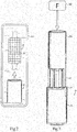
- FIG. 2 there is shown rotor core 18 and fixation sleeve 26 disassembled and shown as they might appear placed within a liquid nitrogen bath 100.
- rotor core 18 and fixation sleeve 26 disassembled and shown as they might appear placed within a liquid nitrogen bath 100.
- fixation sleeve 26 disassembled and shown as they might appear placed within a liquid nitrogen bath 100.
- Those skilled in the art will be familiar with shrinking of materials commonly used in permanent magnet rotor construction when reduced in temperature. Certain other materials, one example of which is the carbon fiber material of which fixation sleeve 26 may be constructed, can actually expand when cooled.
- rotor core 18 and fixation sleeve 26 in bath 100 enables rotor core 18 to shrink and fixation sleeve 26 to expand, so that when fixation sleeve 26 is positioned about rotor core 18 and the components returned to a higher temperature sleeve 26 is shrink fitted about rotor core 18 and magnets 24. Accordingly, shrink fitting fixation sleeve 26 in the manner described, or in another suitable manner, will tend to result in contact with magnets 24 and also produces contact pressure that squeezes magnets 24 radially inward against outer rotor core surface 20.
- pressure tools 40 have the form of cylindrical rods, however, it should be appreciated that in other instances pressure tools 40 might have a different cross sectional shape, might not be uniformly distributed circumferentially about rotor core 18, or might even be multiple pieces or expandable devices that remain within rotor core 18 or are removable. Accordingly, in the present context the term pressure tool should be given a meaning broader than merely a simple rod, shaft or the like.
- FIG. 4 there is shown rotor 16 as it might appear fully assembled and ready for installation into housing 12.
- rotor 16 may be equipped with bearings, bushings, or other hardware commonly positioned about a rotor shaft for supporting and journaling rotor 16.
- FIG 5 there is shown a diagrammatic view of rotor core 18 showing fixation sleeve 26 extending circumferentially about magnets 24 upon rotor core 18, and also including a detailed enlargement. With reference to the detailed enlargement, there can be seen a phantom line 60, just adjacent to a solid line 62 that represents the radially outermost point of outer surface 20.
- Phantom line 60 represents generally one circumferential profile that might be observed prior to press fitting tools 40 into core 18, whereas the solid line shown via reference numeral 62 represents an example outwardly deformed profile that results from the interference fitting. It should be appreciated that the material deformation would likely not be visible to the unaided eye, but as is the case with all interference fits by definition some dimensional change can be expected to occur and is indeed desirable to achieve the biasing of magnets 24.
- each of bores 22 is intersected, typically at their center axis, by a line segment 70 as shown in Figure 5 that extends from longitudinal rotor axis 19 to a different one of the plurality of circumferential locations.
- magnets 24 and bores 22 are generally in circumferential alignment.
- bores 22 are not in circumferential alignment with magnets 24, but instead are offset to a relatively greater or relatively lesser extent, to obtain desirable results of the material deformation occurring responsive to the interference fitting of tools 40.
- grooves 38 extend relatively more deeply into rotor core 18 in a radially inward direction than an outermost extent of bores 22.
- bores 22 and grooves 38 have partially radially overlapping extents. In other instances, bores 22 might be positioned relatively radially further outward or radially inward. It can also be understood from the present description that deformed material of rotor core 18 may be in a first state of compression, such as a higher state of compression, and in an alternating arrangement with material of rotor core 18 that is in a second, lesser state of compression. The relatively greater state of compression may reside in material that is radially between each magnet 24 and the corresponding bore 22, whereas material at the lesser state of compression may be adjacent, such as the material within which adjacent grooves 22 are located. While some plastic deformation of material of rotor core 18 may occur, the deformation may be at least partially elastic such that the increased contact pressure and biasing of magnets 24 against fixation sleeve 26 can be sustained over time and through a range of operating conditions.
Landscapes
- Engineering & Computer Science (AREA)
- Power Engineering (AREA)
- Manufacturing & Machinery (AREA)
- Permanent Field Magnets Of Synchronous Machinery (AREA)
- Iron Core Of Rotating Electric Machines (AREA)
Abstract
Description
- The present disclosure relates generally to permanent magnet rotors of a type used in electrical machines, and relates more particularly to deforming material of a rotor core so as to bias permanent magnets positioned upon the rotor core against a fixation sleeve.
- A great many different construction methods and materials are used in connection with rotating machinery such as electrical generators and electrical motors. Rotating components or "rotors" used in such electrical machines commonly employ a number of different parts. During rotation, inertial forces can impart a tendency for rotor components to migrate from intended positions and potentially fail if unconstrained. For relatively low speed applications, simple component retention techniques such as adhesives can suffice. For higher speed applications, mechanical clamping components, retention sleeves and the like can be used. Known strategies have certain shortcomings in at least certain applications.
- In one aspect, making a permanent magnet rotor includes positioning a fixation sleeve about a rotor core having a plurality of permanent magnets. A plurality of pressure tools are then fitted into bores extending through a rotor core of the assembly, to deform material of the rotor core. Deformation of the material urges the magnets in a radially outward direction against the fixation sleeve to bias the magnets against the fixation sleeve.
-
-
Figure 1 is a partially disassembled cutaway view of a permanent magnet rotor assembly in an electrical machine, according to one embodiment; -
Figure 2 is a diagrammatic view of one part in a process, according to one embodiment; -
Figure 3 is a diagrammatic view of another part in a process, according to one embodiment; -
Figure 4 is a diagrammatic view of a rotor assembly, according to one embodiment; and -
Figure 5 is a partially sectioned diagrammatic view, in perspective, of a rotor assembly according to one embodiment, and including a detailed enlargement. - For the purposes of promoting an understanding of the principles of the PERMANENT MAGNET ROTOR AND METHOD OF MAKING SAME, reference will now be made to the embodiments illustrated in the drawings and specific language will be used to describe the same. It will nevertheless be understood that no limitation of the scope of the invention is thereby intended. Any alterations and further modifications in the described embodiments, and any further applications of the principles of the invention as described herein are contemplated as would normally occur to one skilled in the art to which the invention relates.
- Referring to
Figure 1 , there is shown anelectrical machine system 10, such as an electrical generator or an electrical motor.Machine system 10 may include ahousing 12 wherein astator 14 is positioned. Arotor 16 is positionable withinhousing 12 and rotatable to generate electrical current in windings ofstator 14, or potentially induced to rotate by way of electrical current supplied tostator 14 from an electrical power source such as an electrical power grid. In a practical implementation strategy,rotor 16 may be a relatively high speed rotor commonly having a speed range up to about 200 meters per second at its outermost surfaces, or potentially still greater. Those skilled in the art will be familiar with the relatively high inertial forces at relatively high speeds of rotor rotation. At such speeds, the tendency for components of a rotating rotor, commonly permanent magnets, to be flung outwardly from a rotor core can result in an air gap forming between the rotor core and the permanent magnets, potentially leading to damage or failure in response to fatigue stresses over time, or even to instantaneous and catastrophic failure. As will be further apparent from the following description, rotors according to the present disclosure are uniquely configured for maintaining structural integrity even at high rotational speeds. -
Rotor 16 includes arotor core 18 defining alongitudinal axis 19, and a rotor coreouter surface 20 that extends axially between afirst shaft end 21 and asecond shaft end 23.Shaft ends rotor core 18, but can also be separate pieces attached torotor core 18 such as by welding.Outer surface 20 may have a non-uniform contour, defining various features employed in mounting and retaining other components ofrotor 16 as further discussed herein. -
Rotor core 18 further includes a plurality ofbores 22 extending therethrough. A plurality ofpermanent magnets 24 are mounted upon rotor coreouter surface 20. Anend cap 28 and asecond end cap 30 are positioned at opposite axial ends of a plurality of longitudinal rows ofpermanent magnets 24 in a practical implementation strategy.Spacers permanent magnets 24 uponouter surface 20. A plurality ofmagnet retention elements 36 in the form of elongate rods may be positioned withingrooves 38 formed byouter surface 20. In the illustrated embodiment,elements 36 have a cross section generally similar to an hourglass, although no particular geometry is required. In some embodiments, devices to cancel or suppress eddy currents might also be used inrotor 16. -
Rotor 16 may further include afixation sleeve 26 positioned aboutrotor core 18 andmagnets 24, such thatmagnets 24 are in contact withfixation sleeve 26. In theFigure 1 illustration,sleeve 26 is shown partially in cutaway to illustrate additional features ofrotor 16, however, it will be appreciated thatsleeve 26 will typically extend axially at least as long as necessary to cover and constrain all of themagnets 24 and their associated mounting, retention and positioning hardware.Rotor 16 also includes a plurality ofpressure tools 40 fitted withinbores 22 such as by interference fitting, and deforming material ofrotor core 18 such that the plurality ofpermanent magnets 24 are urged radially outwardly and biased by way of the deformation againstfixation sleeve 26. While pressure tools will typically remain resident withinrotor core 18, in other embodiments they might serve the purposes of material deformation and biasing, and then be removed.Pressure tools 40 might or might not have shapes complementary to shapes ofbores 22, andpressure tools 40 could themselves be deformed by way of the interference fitting. - As noted above,
magnets 24 may be positioned in a plurality of longitudinal rows at a plurality of circumferential locations aboutlongitudinal rotor axis 19.Grooves 38 may be positioned in an alternating arrangement with the plurality of longitudinal rows ofmagnets 24. It can also be seen fromFigure 1 and figures attached but yet to be described thatmagnet retention rods 36 may be shaped so as to circumferentially overlap edges of each ofmagnets 24 in adjacent ones of the longitudinal rows. - Referring also now to
Figure 2 , there is shownrotor core 18 andfixation sleeve 26 disassembled and shown as they might appear placed within aliquid nitrogen bath 100. Those skilled in the art will be familiar with shrinking of materials commonly used in permanent magnet rotor construction when reduced in temperature. Certain other materials, one example of which is the carbon fiber material of whichfixation sleeve 26 may be constructed, can actually expand when cooled. Placingrotor core 18 andfixation sleeve 26 inbath 100 enablesrotor core 18 to shrink andfixation sleeve 26 to expand, so that whenfixation sleeve 26 is positioned aboutrotor core 18 and the components returned to ahigher temperature sleeve 26 is shrink fitted aboutrotor core 18 andmagnets 24. Accordingly, shrinkfitting fixation sleeve 26 in the manner described, or in another suitable manner, will tend to result in contact withmagnets 24 and also produces contact pressure that squeezesmagnets 24 radially inward against outerrotor core surface 20. This contact pressure has been demonstrated to be effective in extending the speed range for a permanent magnet rotor, such that the permanent magnets are not flung outwardly by inertial forces to create an air gap between the magnets and the rotor core at moderately high speeds. It has also been discovered, however, that as speeds increase still further the aforementioned shrink fitting process is not sufficient to keep the permanent magnets from separating from the rotor core. Those skilled in the art will appreciate the practical obstacles to further cooling of parts to be shrink fitted beyond the use of liquid nitrogen as described. Accordingly, the present disclosure can be understood as providing an extension of the speed range of a permanent magnet rotor by providing for an additional mechanism of biasing the permanent magnets against the fixation sleeve as described herein. - To this end, now in reference to
Figure 3 , there is shown aforce producing device 200 and pressingtool 210 in the nature of a hollow cylinder as it might appear contactingpressure tools 40 for pushingpressure tools 40 intorotor core 18. In the illustrated embodiment,pressure tools 40 have the form of cylindrical rods, however, it should be appreciated that in otherinstances pressure tools 40 might have a different cross sectional shape, might not be uniformly distributed circumferentially aboutrotor core 18, or might even be multiple pieces or expandable devices that remain withinrotor core 18 or are removable. Accordingly, in the present context the term pressure tool should be given a meaning broader than merely a simple rod, shaft or the like. - Referring now to
Figure 4 , there is shownrotor 16 as it might appear fully assembled and ready for installation intohousing 12. In addition tofixation sleeve 26 positioned aboutrotor core 18,rotor 16 may be equipped with bearings, bushings, or other hardware commonly positioned about a rotor shaft for supporting and journalingrotor 16. Referring also toFigure 5 , there is shown a diagrammatic view ofrotor core 18 showingfixation sleeve 26 extending circumferentially aboutmagnets 24 uponrotor core 18, and also including a detailed enlargement. With reference to the detailed enlargement, there can be seen aphantom line 60, just adjacent to asolid line 62 that represents the radially outermost point ofouter surface 20. It will be recalled that some deformation of material ofrotor core 18 will occur in response to fitting ofpressure tools 40 intobores 22.Phantom line 60 represents generally one circumferential profile that might be observed prior to pressfitting tools 40 intocore 18, whereas the solid line shown viareference numeral 62 represents an example outwardly deformed profile that results from the interference fitting. It should be appreciated that the material deformation would likely not be visible to the unaided eye, but as is the case with all interference fits by definition some dimensional change can be expected to occur and is indeed desirable to achieve the biasing ofmagnets 24. - In the illustrated embodiment, each of bores 22 is intersected, typically at their center axis, by a line segment 70 as shown in
Figure 5 that extends fromlongitudinal rotor axis 19 to a different one of the plurality of circumferential locations. Another way to understand this design principle is thatmagnets 24 and bores 22 are generally in circumferential alignment. Alternatives are nevertheless contemplated where bores 22 are not in circumferential alignment withmagnets 24, but instead are offset to a relatively greater or relatively lesser extent, to obtain desirable results of the material deformation occurring responsive to the interference fitting oftools 40. It can also be seen thatgrooves 38 extend relatively more deeply intorotor core 18 in a radially inward direction than an outermost extent ofbores 22. Stated another way, bores 22 andgrooves 38 have partially radially overlapping extents. In other instances, bores 22 might be positioned relatively radially further outward or radially inward. It can also be understood from the present description that deformed material ofrotor core 18 may be in a first state of compression, such as a higher state of compression, and in an alternating arrangement with material ofrotor core 18 that is in a second, lesser state of compression. The relatively greater state of compression may reside in material that is radially between eachmagnet 24 and thecorresponding bore 22, whereas material at the lesser state of compression may be adjacent, such as the material within whichadjacent grooves 22 are located. While some plastic deformation of material ofrotor core 18 may occur, the deformation may be at least partially elastic such that the increased contact pressure and biasing ofmagnets 24 againstfixation sleeve 26 can be sustained over time and through a range of operating conditions. - The present description is for illustrative purposes only, and should not be construed to narrow the breadth of the present disclosure in any way. Thus, those skilled in the art will appreciate that various modifications might be made to the presently disclosure embodiments without departing from the full and fair scope and spirit of the present disclosure. For instance, while one example geometry respecting the permanent magnets, and the shape of the outer surface of the rotor core is discussed above and shown in the drawings, the present disclosure is not thereby limited. Rather than longitudinal magnet retention rods or the like the permanent magnets could be mounted directly on the surface of the rotor core and physically constrained solely by the retention sleeve, with preloading and biasing of the permanent magnets being achieved by way of pressure tools as discussed above. Other aspects, features and advantages will be apparent upon an examination of the attached drawings and appended claims.
Claims (15)
- A method of making a permanent magnet rotor comprising:positioning a fixation sleeve about a rotor core assembly having a plurality of permanent magnets mounted upon a rotor core defining a longitudinal axis;fitting a plurality of pressure tools into a plurality of bores extending through the rotor core; anddeforming material of the rotor core via the pressure tools so as to bias the plurality of permanent magnets in a radially outward direction against the fixation sleeve.
- The method of claim 1 wherein the positioning includes shrink fitting the fixation sleeve about the rotor core assembly so as to apply a contact pressure between the fixation sleeve and the plurality of permanent magnets, and such that the bias produced via the deforming of material is in addition to the contact pressure.
- The method of claim 2 wherein the positioning of the fixation sleeve includes positioning a cylindrical carbon fiber fixation sleeve.
- The method of claim 1 wherein the plurality of permanent magnets are mounted at a plurality of circumferential locations about the longitudinal axis, and the plurality of bores are located one between each of the plurality of circumferential locations and the longitudinal axis; and
wherein the plurality of permanent magnets are arranged in a plurality of longitudinal rows each located at one of the plurality of circumferential locations. - The method of claim 1 wherein the fitting includes interference fitting a plurality of rods comprising the plurality of pressure tools.
- The method of claim 5 wherein the fitting includes interference fitting a plurality of cylindrical rods comprising the plurality of pressure tools; or
wherein the positioning includes shrink fitting the fixation sleeve about the rotor core assembly, and the fitting includes simultaneously press fitting the plurality of rods into the plurality of bores. - A permanent magnet rotor comprising:a rotor core including a rotor core outer surface, and having a plurality of bores extending therethrough;a plurality of permanent magnets mounted upon the rotor core outer surface;a fixation sleeve positioned about the rotor core and the plurality of permanent magnets, such that the plurality of permanent magnets are in contact with the fixation sleeve; anda plurality of pressure tools fitted within the plurality of bores and deforming material of the rotor core, such that the plurality of permanent magnets are biased by way of the deformation against the fixation sleeve.
- The rotor assembly of claim 7 wherein the rotor core defines a longitudinal axis, and the plurality of permanent magnets are positioned in a plurality of longitudinal rows at a plurality of circumferential locations about the longitudinal axis.
- The rotor assembly of claim 7 wherein the plurality of bores are intersected by a plurality of line segments each extending from the longitudinal axis to a different one of the plurality of circumferential locations.
- The rotor assembly of claim 8 wherein the rotor core has a plurality of outer grooves formed therein and positioned in an alternating arrangement with the plurality of permanent magnets, and further comprising a plurality of magnet retention rods positioned within the plurality of outer grooves; and
wherein each of the magnet retention rods is shaped so as to circumferentially overlap edges of each of the plurality of permanent magnets in adjacent ones of the longitudinal rows. - The rotor assembly of claim 10 wherein the plurality of pressure tools includes a plurality of rods separate from the magnet retention rods; and
wherein each of the plurality of rods is cylindrical. - The rotor assembly of claim 8 wherein the fixation sleeve includes a carbon fiber fixation sleeve in contact with each of the plurality of permanent magnets.
- The rotor assembly of claim 7 wherein the deformed material of the rotor core is in a first state of compression, and is in an alternating arrangement with material of the rotor core that is in a second state of compression less than the first state; and wherein the fixation sleeve is shrink fitted about the rotor core and the plurality of permanent magnets, and the plurality of pressure tools are interference fitted within the plurality of bores.
- A method of extending a speed range of a rotor in an electrical machine comprising:fitting a plurality of pressure tools into a plurality of bores extending through a rotor core defining a longitudinal axis and having a plurality of permanent magnets mounted thereon; andurging material of the rotor core radially outward via the fitting of the pressure tools so as to increase a contact pressure between each of the plurality of permanent magnets and a fixation sleeve positioned about the plurality of permanent magnets.
- The method of claim 14 wherein the fitting includes interference fitting the plurality of pressure tools so as to increase the contact pressure from a first pressure dependent upon a shrink fitting of the fixation sleeve about the plurality of permanent magnets to a second pressure dependent upon both the shrink fitting and the interference fitting.
Applications Claiming Priority (1)
| Application Number | Priority Date | Filing Date | Title |
|---|---|---|---|
| US14/949,003 US10720808B2 (en) | 2015-11-23 | 2015-11-23 | Method of making a permanent magnet rotor |
Publications (2)
| Publication Number | Publication Date |
|---|---|
| EP3171494A1 true EP3171494A1 (en) | 2017-05-24 |
| EP3171494B1 EP3171494B1 (en) | 2021-11-17 |
Family
ID=57354157
Family Applications (1)
| Application Number | Title | Priority Date | Filing Date |
|---|---|---|---|
| EP16199320.9A Active EP3171494B1 (en) | 2015-11-23 | 2016-11-17 | Permanent magnet rotor and method of making same |
Country Status (3)
| Country | Link |
|---|---|
| US (1) | US10720808B2 (en) |
| EP (1) | EP3171494B1 (en) |
| CN (1) | CN106887913A (en) |
Cited By (2)
| Publication number | Priority date | Publication date | Assignee | Title |
|---|---|---|---|---|
| WO2021198800A1 (en) * | 2020-04-03 | 2021-10-07 | Gomathi Venkatraju | An apparatus for mounting a permanent magnet and a method thereof |
| WO2021225902A1 (en) * | 2020-05-04 | 2021-11-11 | Tesla, Inc. | Permanent magnet motor with wrapping |
Families Citing this family (13)
| Publication number | Priority date | Publication date | Assignee | Title |
|---|---|---|---|---|
| CN107546890B (en) | 2016-06-28 | 2021-07-16 | 特灵国际有限公司 | Harmonic shunting motor, method, AC motor system and variable speed driving system |
| US10826357B2 (en) | 2017-06-28 | 2020-11-03 | Trane International Inc. | Harmonic shunting electric motor with faceted shaft for improved torque transmission |
| US10770936B2 (en) * | 2017-08-10 | 2020-09-08 | Hamilton Sundstrand Corporation | Modular permanent magnet rotor |
| CN108413155B (en) * | 2018-02-06 | 2020-04-10 | 江苏长龄液压股份有限公司 | Middle revolving shaft structure of central revolving joint |
| KR102651736B1 (en) * | 2018-12-19 | 2024-03-26 | 엘지전자 주식회사 | Motor rotor assembly and method for aligning the pole center of permanent magnet therof |
| US11177703B2 (en) * | 2019-08-08 | 2021-11-16 | Garrett Transportation I Inc | Rotor assembly for permanent magnet electric motor with radially biasing shaft structure |
| KR102701979B1 (en) * | 2019-09-05 | 2024-09-02 | 엘지전자 주식회사 | Motor rotor assembly |
| CN110943560A (en) * | 2019-12-24 | 2020-03-31 | 太原理工大学 | Permanent magnet outer rotor elevator |
| CN110977410B (en) * | 2019-12-31 | 2024-11-22 | 嘉兴丰沃增压技术有限公司 | A carbon fiber tube press-fitting tool for electric compressor rotor assembly |
| EP4037158B1 (en) | 2021-02-02 | 2025-07-30 | Black & Decker, Inc. | Brushless motor including a nested bearing bridge |
| US12592598B2 (en) | 2024-03-22 | 2026-03-31 | Borgwarner Luxembourg Automotive Systems Sa | Systems for rotor including composite material |
| CN119561325B (en) * | 2024-11-08 | 2025-10-21 | 武汉船用电力推进装置研究所(中国船舶集团有限公司第七一二研究所) | Surface mount permanent magnet installation and positioning tooling |
| CN120728918B (en) * | 2025-08-27 | 2026-03-03 | 山东天瑞重工有限公司 | A high-speed motor rotor structure with optimized interference fit |
Citations (8)
| Publication number | Priority date | Publication date | Assignee | Title |
|---|---|---|---|---|
| JPS6212359A (en) * | 1985-07-08 | 1987-01-21 | Mitsuba Electric Mfg Co Ltd | Rotor of magneto generator |
| FR2707813A1 (en) * | 1993-07-16 | 1995-01-20 | Mitsuba Electric Mfg Co | Rotor of magnetogenerator and method of manufacturing it |
| US5581140A (en) * | 1992-09-02 | 1996-12-03 | Kabushiki Kaisha Toshiba | Permanent magnetic rotor and producing apparatus of the same |
| US20020079770A1 (en) * | 2000-12-26 | 2002-06-27 | Industrial Technology Research Institute | Permanent magnet rotor having magnet positioning and retaining means |
| EP1533883A1 (en) * | 2003-11-18 | 2005-05-25 | SISME IMMOBILIARE S.p.A. | Quickly assembled permanent magnet rotor for electric motor, and constructional method therefor |
| WO2007004009A2 (en) * | 2005-06-30 | 2007-01-11 | Spal Automotive S.R.L. | A rotor for an electrical machine |
| US20090102304A1 (en) * | 2007-10-23 | 2009-04-23 | Mitsubishi Electric Corporation | Rotor of rotating electrical machine and manufacturing method there for |
| US20130009494A1 (en) * | 2011-07-05 | 2013-01-10 | Nidec Corporation | Motor and method of manufacturing motor |
Family Cites Families (11)
| Publication number | Priority date | Publication date | Assignee | Title |
|---|---|---|---|---|
| US5140210A (en) | 1988-07-07 | 1992-08-18 | Mitsubishi Denki K.K. | Permanent-magnet type dynamoelectric machine rotor |
| JPH0678482A (en) | 1992-08-25 | 1994-03-18 | Daikin Ind Ltd | Permanent magnet type rotor and manufacturing method thereof |
| US5801470A (en) * | 1996-12-19 | 1998-09-01 | General Electric Company | Rotors with retaining cylinders and reduced harmonic field effect losses |
| DE10348394A1 (en) | 2003-10-17 | 2005-06-02 | Robert Bosch Gmbh | Rotor for an electric machine with improved temperature resistance |
| JP4558478B2 (en) | 2004-12-28 | 2010-10-06 | 日立オートモティブシステムズ株式会社 | Rotating machine rotor, manufacturing method thereof, and motor for electric power steering |
| DE102007062010A1 (en) | 2007-10-19 | 2009-04-23 | Kaltenbach & Voigt Gmbh | Rotor for electric motor, electric motor and dental handpiece |
| JP5292380B2 (en) * | 2009-11-16 | 2013-09-18 | 西芝電機株式会社 | Permanent magnet type rotating electrical machine rotor |
| JP5490056B2 (en) | 2011-05-17 | 2014-05-14 | 三菱電機株式会社 | Embedded magnet rotating electric machine |
| CN102738928A (en) * | 2012-04-24 | 2012-10-17 | 重庆通赛机电有限公司 | Brushless drive motor rotor |
| JP6212359B2 (en) | 2013-10-31 | 2017-10-11 | 日本製紙クレシア株式会社 | Package |
| US20160049845A1 (en) * | 2014-08-12 | 2016-02-18 | Zilift Holdings, Limited | Magnetic rotor shaft module and a rotor assembly incorporating the same |
-
2015
- 2015-11-23 US US14/949,003 patent/US10720808B2/en not_active Expired - Fee Related
-
2016
- 2016-11-17 EP EP16199320.9A patent/EP3171494B1/en active Active
- 2016-11-22 CN CN201611029105.5A patent/CN106887913A/en active Pending
Patent Citations (8)
| Publication number | Priority date | Publication date | Assignee | Title |
|---|---|---|---|---|
| JPS6212359A (en) * | 1985-07-08 | 1987-01-21 | Mitsuba Electric Mfg Co Ltd | Rotor of magneto generator |
| US5581140A (en) * | 1992-09-02 | 1996-12-03 | Kabushiki Kaisha Toshiba | Permanent magnetic rotor and producing apparatus of the same |
| FR2707813A1 (en) * | 1993-07-16 | 1995-01-20 | Mitsuba Electric Mfg Co | Rotor of magnetogenerator and method of manufacturing it |
| US20020079770A1 (en) * | 2000-12-26 | 2002-06-27 | Industrial Technology Research Institute | Permanent magnet rotor having magnet positioning and retaining means |
| EP1533883A1 (en) * | 2003-11-18 | 2005-05-25 | SISME IMMOBILIARE S.p.A. | Quickly assembled permanent magnet rotor for electric motor, and constructional method therefor |
| WO2007004009A2 (en) * | 2005-06-30 | 2007-01-11 | Spal Automotive S.R.L. | A rotor for an electrical machine |
| US20090102304A1 (en) * | 2007-10-23 | 2009-04-23 | Mitsubishi Electric Corporation | Rotor of rotating electrical machine and manufacturing method there for |
| US20130009494A1 (en) * | 2011-07-05 | 2013-01-10 | Nidec Corporation | Motor and method of manufacturing motor |
Cited By (2)
| Publication number | Priority date | Publication date | Assignee | Title |
|---|---|---|---|---|
| WO2021198800A1 (en) * | 2020-04-03 | 2021-10-07 | Gomathi Venkatraju | An apparatus for mounting a permanent magnet and a method thereof |
| WO2021225902A1 (en) * | 2020-05-04 | 2021-11-11 | Tesla, Inc. | Permanent magnet motor with wrapping |
Also Published As
| Publication number | Publication date |
|---|---|
| US10720808B2 (en) | 2020-07-21 |
| EP3171494B1 (en) | 2021-11-17 |
| CN106887913A (en) | 2017-06-23 |
| US20170149296A1 (en) | 2017-05-25 |
Similar Documents
| Publication | Publication Date | Title |
|---|---|---|
| US10720808B2 (en) | Method of making a permanent magnet rotor | |
| US10355544B2 (en) | Rotor member fixed to rotary shaft of electrical rotating machine, rotor, rotary electric machine and method for disassembling rotor | |
| US8669685B2 (en) | Wind power turbine for producing electric energy | |
| US10505433B2 (en) | Squirrel-cage rotor, and asynchronous motor comprising such a rotor | |
| CA2771922C (en) | Turbomachine | |
| CN104702003A (en) | Rotor and dynamo-electric machine having the same | |
| EP2722547A1 (en) | Insulated bearing ring | |
| EP3022829B1 (en) | A rotor for an electric motor | |
| GB2538516A (en) | Generator | |
| US7812495B2 (en) | Sleeve in end rings for permanent magnet rotor | |
| US20180278106A1 (en) | Rotor for induction motor and induction motor | |
| CN101420140A (en) | Rotor of rotary motor and production method thereof | |
| CN114846249B (en) | Electric machine with releasable bearing assembly | |
| JP2019515630A (en) | Hydroelectric generator, method of manufacturing the same and method of operating the same | |
| US20180323666A1 (en) | Interior permanent magnet rotor hubs | |
| KR102835931B1 (en) | A rotor of an induction machine and a method for assembling a cage winding of the rotor | |
| US10546091B2 (en) | Magnetic mass for rotor, and corresponding rotor, electric machine and manufacturing method | |
| EP2787607A2 (en) | Electric machine rotor | |
| JP2020115730A (en) | Rotor of rotary electric machine | |
| KR101981021B1 (en) | How to fasten the pole wheel on the shaft of the electric rotating machine | |
| WO2017218316A1 (en) | Retention sleeve and balance strategy for a high speed permanent magnet rotor | |
| JP6370521B1 (en) | Rotor and rotating electric machine | |
| US20150022036A1 (en) | Rotor with non-cylindrical surface for dynamoelectric machine | |
| CN107681795A (en) | Electric rotating machine | |
| JP2022525657A (en) | Claw pole stator for lateral flux machines |
Legal Events
| Date | Code | Title | Description |
|---|---|---|---|
| PUAI | Public reference made under article 153(3) epc to a published international application that has entered the european phase |
Free format text: ORIGINAL CODE: 0009012 |
|
| STAA | Information on the status of an ep patent application or granted ep patent |
Free format text: STATUS: REQUEST FOR EXAMINATION WAS MADE |
|
| 17P | Request for examination filed |
Effective date: 20161117 |
|
| AK | Designated contracting states |
Kind code of ref document: A1 Designated state(s): AL AT BE BG CH CY CZ DE DK EE ES FI FR GB GR HR HU IE IS IT LI LT LU LV MC MK MT NL NO PL PT RO RS SE SI SK SM TR |
|
| AX | Request for extension of the european patent |
Extension state: BA ME |
|
| STAA | Information on the status of an ep patent application or granted ep patent |
Free format text: STATUS: EXAMINATION IS IN PROGRESS |
|
| 17Q | First examination report despatched |
Effective date: 20190502 |
|
| RAP1 | Party data changed (applicant data changed or rights of an application transferred) |
Owner name: INGERSOLL-RAND INDUSTRIAL U.S., INC. |
|
| GRAP | Despatch of communication of intention to grant a patent |
Free format text: ORIGINAL CODE: EPIDOSNIGR1 |
|
| STAA | Information on the status of an ep patent application or granted ep patent |
Free format text: STATUS: GRANT OF PATENT IS INTENDED |
|
| INTG | Intention to grant announced |
Effective date: 20210701 |
|
| GRAS | Grant fee paid |
Free format text: ORIGINAL CODE: EPIDOSNIGR3 |
|
| GRAA | (expected) grant |
Free format text: ORIGINAL CODE: 0009210 |
|
| STAA | Information on the status of an ep patent application or granted ep patent |
Free format text: STATUS: THE PATENT HAS BEEN GRANTED |
|
| AK | Designated contracting states |
Kind code of ref document: B1 Designated state(s): AL AT BE BG CH CY CZ DE DK EE ES FI FR GB GR HR HU IE IS IT LI LT LU LV MC MK MT NL NO PL PT RO RS SE SI SK SM TR |
|
| REG | Reference to a national code |
Ref country code: GB Ref legal event code: FG4D |
|
| REG | Reference to a national code |
Ref country code: IE Ref legal event code: FG4D |
|
| REG | Reference to a national code |
Ref country code: DE Ref legal event code: R096 Ref document number: 602016066258 Country of ref document: DE |
|
| REG | Reference to a national code |
Ref country code: AT Ref legal event code: REF Ref document number: 1448861 Country of ref document: AT Kind code of ref document: T Effective date: 20211215 |
|
| PGFP | Annual fee paid to national office [announced via postgrant information from national office to epo] |
Ref country code: GB Payment date: 20211130 Year of fee payment: 6 |
|
| REG | Reference to a national code |
Ref country code: LT Ref legal event code: MG9D |
|
| REG | Reference to a national code |
Ref country code: NL Ref legal event code: MP Effective date: 20211117 |
|
| REG | Reference to a national code |
Ref country code: AT Ref legal event code: MK05 Ref document number: 1448861 Country of ref document: AT Kind code of ref document: T Effective date: 20211117 |
|
| PG25 | Lapsed in a contracting state [announced via postgrant information from national office to epo] |
Ref country code: RS Free format text: LAPSE BECAUSE OF FAILURE TO SUBMIT A TRANSLATION OF THE DESCRIPTION OR TO PAY THE FEE WITHIN THE PRESCRIBED TIME-LIMIT Effective date: 20211117 Ref country code: LT Free format text: LAPSE BECAUSE OF FAILURE TO SUBMIT A TRANSLATION OF THE DESCRIPTION OR TO PAY THE FEE WITHIN THE PRESCRIBED TIME-LIMIT Effective date: 20211117 Ref country code: FI Free format text: LAPSE BECAUSE OF FAILURE TO SUBMIT A TRANSLATION OF THE DESCRIPTION OR TO PAY THE FEE WITHIN THE PRESCRIBED TIME-LIMIT Effective date: 20211117 Ref country code: BG Free format text: LAPSE BECAUSE OF FAILURE TO SUBMIT A TRANSLATION OF THE DESCRIPTION OR TO PAY THE FEE WITHIN THE PRESCRIBED TIME-LIMIT Effective date: 20220217 Ref country code: AT Free format text: LAPSE BECAUSE OF FAILURE TO SUBMIT A TRANSLATION OF THE DESCRIPTION OR TO PAY THE FEE WITHIN THE PRESCRIBED TIME-LIMIT Effective date: 20211117 |
|
| PG25 | Lapsed in a contracting state [announced via postgrant information from national office to epo] |
Ref country code: IS Free format text: LAPSE BECAUSE OF FAILURE TO SUBMIT A TRANSLATION OF THE DESCRIPTION OR TO PAY THE FEE WITHIN THE PRESCRIBED TIME-LIMIT Effective date: 20220317 Ref country code: SE Free format text: LAPSE BECAUSE OF FAILURE TO SUBMIT A TRANSLATION OF THE DESCRIPTION OR TO PAY THE FEE WITHIN THE PRESCRIBED TIME-LIMIT Effective date: 20211117 Ref country code: PT Free format text: LAPSE BECAUSE OF FAILURE TO SUBMIT A TRANSLATION OF THE DESCRIPTION OR TO PAY THE FEE WITHIN THE PRESCRIBED TIME-LIMIT Effective date: 20220317 Ref country code: PL Free format text: LAPSE BECAUSE OF FAILURE TO SUBMIT A TRANSLATION OF THE DESCRIPTION OR TO PAY THE FEE WITHIN THE PRESCRIBED TIME-LIMIT Effective date: 20211117 Ref country code: NO Free format text: LAPSE BECAUSE OF FAILURE TO SUBMIT A TRANSLATION OF THE DESCRIPTION OR TO PAY THE FEE WITHIN THE PRESCRIBED TIME-LIMIT Effective date: 20220217 Ref country code: NL Free format text: LAPSE BECAUSE OF FAILURE TO SUBMIT A TRANSLATION OF THE DESCRIPTION OR TO PAY THE FEE WITHIN THE PRESCRIBED TIME-LIMIT Effective date: 20211117 Ref country code: LV Free format text: LAPSE BECAUSE OF FAILURE TO SUBMIT A TRANSLATION OF THE DESCRIPTION OR TO PAY THE FEE WITHIN THE PRESCRIBED TIME-LIMIT Effective date: 20211117 Ref country code: HR Free format text: LAPSE BECAUSE OF FAILURE TO SUBMIT A TRANSLATION OF THE DESCRIPTION OR TO PAY THE FEE WITHIN THE PRESCRIBED TIME-LIMIT Effective date: 20211117 Ref country code: GR Free format text: LAPSE BECAUSE OF FAILURE TO SUBMIT A TRANSLATION OF THE DESCRIPTION OR TO PAY THE FEE WITHIN THE PRESCRIBED TIME-LIMIT Effective date: 20220218 Ref country code: ES Free format text: LAPSE BECAUSE OF FAILURE TO SUBMIT A TRANSLATION OF THE DESCRIPTION OR TO PAY THE FEE WITHIN THE PRESCRIBED TIME-LIMIT Effective date: 20211117 |
|
| REG | Reference to a national code |
Ref country code: CH Ref legal event code: PL |
|
| PG25 | Lapsed in a contracting state [announced via postgrant information from national office to epo] |
Ref country code: SM Free format text: LAPSE BECAUSE OF FAILURE TO SUBMIT A TRANSLATION OF THE DESCRIPTION OR TO PAY THE FEE WITHIN THE PRESCRIBED TIME-LIMIT Effective date: 20211117 Ref country code: SK Free format text: LAPSE BECAUSE OF FAILURE TO SUBMIT A TRANSLATION OF THE DESCRIPTION OR TO PAY THE FEE WITHIN THE PRESCRIBED TIME-LIMIT Effective date: 20211117 Ref country code: RO Free format text: LAPSE BECAUSE OF FAILURE TO SUBMIT A TRANSLATION OF THE DESCRIPTION OR TO PAY THE FEE WITHIN THE PRESCRIBED TIME-LIMIT Effective date: 20211117 Ref country code: LU Free format text: LAPSE BECAUSE OF NON-PAYMENT OF DUE FEES Effective date: 20211117 Ref country code: EE Free format text: LAPSE BECAUSE OF FAILURE TO SUBMIT A TRANSLATION OF THE DESCRIPTION OR TO PAY THE FEE WITHIN THE PRESCRIBED TIME-LIMIT Effective date: 20211117 Ref country code: DK Free format text: LAPSE BECAUSE OF FAILURE TO SUBMIT A TRANSLATION OF THE DESCRIPTION OR TO PAY THE FEE WITHIN THE PRESCRIBED TIME-LIMIT Effective date: 20211117 Ref country code: CZ Free format text: LAPSE BECAUSE OF FAILURE TO SUBMIT A TRANSLATION OF THE DESCRIPTION OR TO PAY THE FEE WITHIN THE PRESCRIBED TIME-LIMIT Effective date: 20211117 Ref country code: BE Free format text: LAPSE BECAUSE OF NON-PAYMENT OF DUE FEES Effective date: 20211130 |
|
| REG | Reference to a national code |
Ref country code: BE Ref legal event code: MM Effective date: 20211130 |
|
| REG | Reference to a national code |
Ref country code: DE Ref legal event code: R097 Ref document number: 602016066258 Country of ref document: DE |
|
| PG25 | Lapsed in a contracting state [announced via postgrant information from national office to epo] |
Ref country code: MC Free format text: LAPSE BECAUSE OF FAILURE TO SUBMIT A TRANSLATION OF THE DESCRIPTION OR TO PAY THE FEE WITHIN THE PRESCRIBED TIME-LIMIT Effective date: 20211117 |
|
| PLBE | No opposition filed within time limit |
Free format text: ORIGINAL CODE: 0009261 |
|
| STAA | Information on the status of an ep patent application or granted ep patent |
Free format text: STATUS: NO OPPOSITION FILED WITHIN TIME LIMIT |
|
| 26N | No opposition filed |
Effective date: 20220818 |
|
| PG25 | Lapsed in a contracting state [announced via postgrant information from national office to epo] |
Ref country code: IE Free format text: LAPSE BECAUSE OF NON-PAYMENT OF DUE FEES Effective date: 20211117 Ref country code: AL Free format text: LAPSE BECAUSE OF FAILURE TO SUBMIT A TRANSLATION OF THE DESCRIPTION OR TO PAY THE FEE WITHIN THE PRESCRIBED TIME-LIMIT Effective date: 20211117 |
|
| REG | Reference to a national code |
Ref country code: FR Ref legal event code: PLFP Year of fee payment: 7 |
|
| PG25 | Lapsed in a contracting state [announced via postgrant information from national office to epo] |
Ref country code: SI Free format text: LAPSE BECAUSE OF FAILURE TO SUBMIT A TRANSLATION OF THE DESCRIPTION OR TO PAY THE FEE WITHIN THE PRESCRIBED TIME-LIMIT Effective date: 20211117 |
|
| PG25 | Lapsed in a contracting state [announced via postgrant information from national office to epo] |
Ref country code: HU Free format text: LAPSE BECAUSE OF FAILURE TO SUBMIT A TRANSLATION OF THE DESCRIPTION OR TO PAY THE FEE WITHIN THE PRESCRIBED TIME-LIMIT; INVALID AB INITIO Effective date: 20161117 |
|
| P01 | Opt-out of the competence of the unified patent court (upc) registered |
Effective date: 20230523 |
|
| PG25 | Lapsed in a contracting state [announced via postgrant information from national office to epo] |
Ref country code: CY Free format text: LAPSE BECAUSE OF FAILURE TO SUBMIT A TRANSLATION OF THE DESCRIPTION OR TO PAY THE FEE WITHIN THE PRESCRIBED TIME-LIMIT Effective date: 20211117 |
|
| GBPC | Gb: european patent ceased through non-payment of renewal fee |
Effective date: 20221117 |
|
| PG25 | Lapsed in a contracting state [announced via postgrant information from national office to epo] |
Ref country code: LI Free format text: LAPSE BECAUSE OF NON-PAYMENT OF DUE FEES Effective date: 20220630 Ref country code: CH Free format text: LAPSE BECAUSE OF NON-PAYMENT OF DUE FEES Effective date: 20220630 |
|
| PG25 | Lapsed in a contracting state [announced via postgrant information from national office to epo] |
Ref country code: GB Free format text: LAPSE BECAUSE OF NON-PAYMENT OF DUE FEES Effective date: 20221117 |
|
| PG25 | Lapsed in a contracting state [announced via postgrant information from national office to epo] |
Ref country code: MK Free format text: LAPSE BECAUSE OF FAILURE TO SUBMIT A TRANSLATION OF THE DESCRIPTION OR TO PAY THE FEE WITHIN THE PRESCRIBED TIME-LIMIT Effective date: 20211117 |
|
| PG25 | Lapsed in a contracting state [announced via postgrant information from national office to epo] |
Ref country code: TR Free format text: LAPSE BECAUSE OF FAILURE TO SUBMIT A TRANSLATION OF THE DESCRIPTION OR TO PAY THE FEE WITHIN THE PRESCRIBED TIME-LIMIT Effective date: 20211117 |
|
| PG25 | Lapsed in a contracting state [announced via postgrant information from national office to epo] |
Ref country code: MT Free format text: LAPSE BECAUSE OF FAILURE TO SUBMIT A TRANSLATION OF THE DESCRIPTION OR TO PAY THE FEE WITHIN THE PRESCRIBED TIME-LIMIT Effective date: 20211117 |
|
| PGFP | Annual fee paid to national office [announced via postgrant information from national office to epo] |
Ref country code: DE Payment date: 20251127 Year of fee payment: 10 |
|
| PGFP | Annual fee paid to national office [announced via postgrant information from national office to epo] |
Ref country code: IT Payment date: 20251127 Year of fee payment: 10 |
|
| PGFP | Annual fee paid to national office [announced via postgrant information from national office to epo] |
Ref country code: FR Payment date: 20251127 Year of fee payment: 10 |