EP3171462A1 - Electric connector with secondary locking member and electric connector assembly - Google Patents
Electric connector with secondary locking member and electric connector assembly Download PDFInfo
- Publication number
- EP3171462A1 EP3171462A1 EP16199361.3A EP16199361A EP3171462A1 EP 3171462 A1 EP3171462 A1 EP 3171462A1 EP 16199361 A EP16199361 A EP 16199361A EP 3171462 A1 EP3171462 A1 EP 3171462A1
- Authority
- EP
- European Patent Office
- Prior art keywords
- electric connector
- locking lever
- locking member
- lever
- complementary
- Prior art date
- Legal status (The legal status is an assumption and is not a legal conclusion. Google has not performed a legal analysis and makes no representation as to the accuracy of the status listed.)
- Granted
Links
Images



Classifications
-
- H—ELECTRICITY
- H01—ELECTRIC ELEMENTS
- H01R—ELECTRICALLY-CONDUCTIVE CONNECTIONS; STRUCTURAL ASSOCIATIONS OF A PLURALITY OF MUTUALLY-INSULATED ELECTRICAL CONNECTING ELEMENTS; COUPLING DEVICES; CURRENT COLLECTORS
- H01R13/00—Details of coupling devices of the kinds covered by groups H01R12/70 or H01R24/00 - H01R33/00
- H01R13/62—Means for facilitating engagement or disengagement of coupling parts or for holding them in engagement
- H01R13/629—Additional means for facilitating engagement or disengagement of coupling parts, e.g. aligning or guiding means, levers, gas pressure electrical locking indicators, manufacturing tolerances
- H01R13/62933—Comprising exclusively pivoting lever
- H01R13/62955—Pivoting lever comprising supplementary/additional locking means
Definitions
- the invention relates to an electric connector with a U-shaped locking lever, the locking lever being held rotatably around an axis of rotation in the electric connector for engagement to a complementary electric connector.
- the invention further relates to an electric connector assembly comprising an electric connector with a U-shaped locking lever held rotatably around an axis of rotation in the electric connector from an open position to a locked position, a complementary electric connector adapted to be connected to the electric connector, wherein, in the locked position of the locking lever, the electric connector and the complementary electric connector are engaged in a primary lock.
- One objective of the present invention is therefore to provide an electric connector and an electric connector assembly which provides a secondary lock for securing the primary lock and for preventing the electric connector assembly from unlocking by chance or by misuse.
- the electric connector of the aforementioned type solves this problem by providing the locking lever with a secondary locking member for additional engagement to the complementary electric connector, the secondary locking member being fixed to the locking lever slidably along an insertion direction, which is substantially perpendicular to the axis of rotation, into the locking lever from a first to a second position.
- the electric connector assembly of the aforementioned type solves this problem by providing the locking lever with a secondary locking member, the secondary locking member being adapted to be slid on the locking lever perpendicular to the axis of rotation into engagement with the complementary electric connector to form a secondary lock.
- Those solutions provide a secured primary lock, which may not be unlocked prior to disengaging the secondary lock, whereas the secondary lock may, in particular, not be disengaged by hand and may therefore prevent disengagement of the secondary lock by chance or by misuse.
- Another objective of the inventive electric connector and the inventive electric connector assembly may be prevention of an incomplete engagement of the electric connector to the complementary electric connector, which may not be secured by the locking lever and which may be disengaged by chance or for instance vibrations of the electric connector assembly.
- Engagement of the secondary lock between the electric connector and the complementary electric connector may only be possible after engagement of the primary lock.
- the secondary locking member is U-shaped.
- a U-shaped secondary locking member has the advantage that the secondary locking member may be firmly fixed to the locking lever, not altering the general shape or the size of the electric connector.
- the U-shaped secondary locking member may in particular comprise two opposing longitudinal structures connected to each other by a common base, wherein the longitudinal structures are oriented substantially perpendicular to the base.
- the secondary locking member may comprise connection portions connecting the longitudinal structures of the secondary locking member to the base, wherein said connection portions may be embodied with a substantially rectangular edge or may be embodied as a rounding with a rounding radius of up to half the distance between the longitudinal structures of the secondary locking member.
- the secondary locking member has at least two legs which form a pocket in which at least a section of a leg of the locking lever is received.
- Receiving the locking lever in the pocket of the secondary locking member has the advantage that fixing the secondary locking member to the locking lever, as well as guiding the secondary locking member along the insertion direction into the locking lever, is facilitated.
- the pocket of the secondary locking member may in particular receive a section of each of the two legs of the locking lever.
- the at least two legs comprise an inner leg and an outer leg on the outside of the leg of the locking lever, the inner leg being shorter than the outer leg.
- the inner leg may be located on the side of the locking lever which is closer to an opposite leg of the locking lever.
- the inner leg may be located in a space between the legs of the locking lever and the outer leg on the outside of this space.
- the inner leg and the outer leg of the secondary locking member may therefore form a sub-pocket for receiving at least a portion of the wall of the locking lever, therefore allowing an easy and secure fixation, and guidance of the secondary locking member to and within the locking lever.
- the inner leg extends parallel to and is spaced apart from the leg of the locking lever received in the pocket adjacent to this inner leg.
- the leg of the locking lever may preferentially be received in the sub-pocket adjacent to the inner leg, the sub-pocket may be formed between the inner and the outer leg.
- Such a spacing may allow the inner leg to be deflected towards the leg of the locking lever, which may be advantageous to allow for an imperfect insertion of the secondary locking member into the locking lever that is not along the insertion direction, but with an angle to the insertion direction without blocking the insertion of the secondary locking member.
- the spacing may be adapted to allow a deflection of the inner leg by up to one width of the inner leg, wherein the width is measured in the direction of deflection.
- the deflection of the inner leg may be limited by a maximum deflection of the inner leg or by an abutment of the inner leg with the leg of the locking lever.
- the inner leg may be attached to the base of the secondary locking member by a reinforced pedestal which may be adapted to limit the deflection of the inner leg and/or may be adapted to transfer shear forces, which are due to deflection of the inner leg, to the base of the secondary locking member.
- the spacing between the inner leg and the leg of the locking lever is decreased with respect to the first position or the inner leg abuts the leg of the locking lever.
- a reduced spacing in the second position may prevent engaging the primary lock by rotating the locking lever with the secondary locking member being in the second position.
- the side of the leg of the locking lever facing towards the volume between the legs of the locking lever may comprise a chamfer, which substantially faces towards the inner leg, that is, the chamfer is tilted from the insertion direction towards the base of the secondary locking member.
- the inner leg may pass by this chamfer or may touch the chamfer resulting in a deflection of the inner leg away from the spacing leading to an abutment between the inner leg and the leg of the locking lever.
- the inner leg protrudes into a volume between the legs of the locking lever.
- the inner leg may protrude into the volume only in the second position, or in both the first and the second position of the secondary locking member. Similarly to the at least one protrusion extending into the volume between the legs of the locking lever, the inner leg may be part of or may support the secondary lock between the electric connector and the complementary electric connector.
- the outer leg is provided with a locking element that locks the secondary locking member in the first position.
- a locking element prevents an unwanted unmounting of the secondary locking member from the locking lever.
- the locking element may be embodied as a detent hook with an inclined surface, substantially facing away from the base of the secondary locking member and a shoulder being substantially oriented parallel to and facing towards the base of the secondary locking member.
- the locking lever may comprise hook receptacles adapted to slidingly receive the detent hook of the secondary locking member, the hook receptacles may comprise a first receptacle wall facing substantially in the insertion direction, thus, facing opposite to the shoulder of the detent hook of the secondary locking member installed to the locking lever.
- Abutment of the first receptacle wall of the locking lever and the shoulder of the detent hook may occur in the first position of the secondary locking member or when the secondary locking member is moved opposite to the insertion direction out of the locking lever.
- the secondary locking member has a base section extending parallel to a lever base section connecting the legs of the locking lever, the base section being provided with at least one protrusion that, at least in the second position, protrudes through at least one opening of the locking lever into the volume between the legs of the locking lever.
- the at least one protrusion may be a part of, or may support the secondary lock between the electric connector and the complementary electric connector.
- the at least one protrusion may not extend into the volume between the legs of the locking lever.
- This embodiment has the advantage that the locking lever may be rotated around the axis of rotation without the at least one protrusion blocking this rotational movement by touching any structure located in the volume between the legs of the locking lever.
- the at least one protrusion may be embodied as a locking tooth, wherein several locking teeth may be provided symmetrically or asymmetrically along the base section of the secondary locking member.
- the at least one protrusion may be embodied as one single protrusion extending along the whole base section of the secondary locking member.
- Such a catch has the advantage that the first and the second position may be clearly distinct from any intermediate position of the secondary locking member between the first and the second position.
- This catch may further comprise indication means providing a feedback to the end-user, and allowing for an indication in which position the secondary locking member is located.
- the catch may be embodied as a catch member comprising inclined surfaces, wherein the surface being located closer to the base of the secondary locking member is inclined towards this base and wherein the surface being located further from the base of the secondary locking member is inclined away from this base.
- Such a catch member may be adapted to be received in a catch receptacle which may be embodied as a hole in the leg of the locking lever. Two of such catch receptacles may be provided in the leg of the locking lever according to the first and the second position of the secondary locking member.
- the secondary locking member is provided with a plate-like handling member, which protrudes from the locking lever in a direction facing away from the volume between the legs of the locking lever and in that, in the second position, the handling member comprises a section which is spaced apart from the locking lever and thus defines a tool insertion space.
- the plate-like handling member may be adapted to transfer a handling force exerted on the handling member to the secondary locking member.
- the handling member may preferentially be located in a central portion of the base of the secondary locking member in order to allow for a symmetric exertion of the handling force to the secondary locking member.
- the locking lever may comprise a lever handle also extending substantially away from the volume between the legs of the locking lever, whereas this lever handle may at least partially prevent accessing the handling member.
- the tool insertion space may be adapted to receive a release tool such as a screw driver in order to move the secondary locking member from the second position to the first position.
- a release tool such as a screw driver
- the lock of the catch member with the catch receptacle may therefore be sufficiently strong to prevent a movement of the secondary locking member from the second position to the first position by hand.
- the inventive electric connector assembly of the aforementioned type may be adapted to allow a movement of the secondary locking member from the first and second position only in the locked position of the locking lever that is after engagement of the electric connector and the complementary electric connector in the primary lock.
- the secondary locking member engages with a complementary locking member of the complementary electric connector, the complementary locking member being one of a stepped surface, a protrusion or a recess of the complementary electric connector located in the volume between the legs of the locking lever.
- the complementary locking member may be embodied as an at least partially circumferential edge which may be present per se at the complementary electric connector.
- the complementary locking member may be located in the volume between the legs of the locking lever in both, the open and the locked position of the locking lever, but may as well be only located in said volume when the locking lever is moved to the locked position.
- the overlap between the complementary locking member which may be embodied as a stepped surface, may be quite small, in the order of 1 mm, in order to achieve a reliable locking effect. Therefore a compact design may be combined with an efficient locking effect.
- the locking lever may only be moved from the open to the locked position with the secondary locking member in the first position, whereas when the secondary locking member is in the second position, movement of the locking lever from the open to the closed position may be prevented.
- a procedure for engaging the primary and the secondary lock between the electric connector and the complementary electric connector may comprise the following steps:
- the inner legs and the at least one protrusion extending from the base of the secondary locking member may already extend into the volume between the legs of the locking lever, whereas a spacing between the complementary electric connector and the locking lever may allow the inner legs and/or the at least one protrusion to extend into the volume between the legs of the locking lever without touching the complementary electric connector when the locking lever is moved from the open position to the locked position.
- pushing the handling member may insert the inner legs and/or the at least one protrusion into the volume or further into the volume between the legs of the locking lever.
- the inner legs and/or the at least one protrusion may be moved or slid along the complementary locking member of the complementary electric connector in an overlapping manner, thus engaging a positive lock between the complementary locking member and the secondary locking member.
- the complementary locking member abuts the inner legs and/or the at least one protrusion such that a movement of the locking lever from the locked position to the open position is blocked.
- abutment regions between the complementary locking member and the secondary locking member are advantageous as they may allow distribution of a force exerted on the locking lever in the direction of the open position into the complementary electric connector, into the locking lever and into the secondary locking member.
- the at least one inner leg of the secondary locking member is adapted to be deflected by the complementary electric connector towards the locking lever in the first position of the secondary locking member and in that the locking lever is adapted to be moved into engagement with the complementary electric connector with the secondary locking member fixed to the locking lever in the first position.
- Such a spacing may be advantageous if the secondary locking member is mounted to the locking lever in a direction with an angle to the insertion direction. In such a case, insertion of the secondary locking member is not blocked by abutment of the legs of the secondary locking member with the locking lever.
- the secondary locking member is snapped over the complementary locking member of the complementary electric connector when the electric connector is engaged in the primary lock with the complementary electric connector.
- the at least one inner leg of the secondary locking member may be snapped over the complementary locking member.
- the at least one inner leg of the secondary locking member may be slid along a housing of the complementary electric connector, wherein prior to completion of the primary lock between the electric connector and the complementary electric connector the at least one inner leg of the secondary locking member may snap over the complementary locking member.
- This abutment may cause a deflection of the inner leg towards the leg of the locking lever, whereas the deflected inner leg may be slidably moved together with the locking lever rotated from the open position to the locked position.
- the inner leg remains deflected and slides above the complementary electric connector until reaching the complementary locking member of the complementary electric connector.
- the inner leg When reaching the complementary locking member, the inner leg may return to its relaxed state, that is the non-deflected state by a snapping movement over said complementary locking member.
- the state reached after this snapping movement may be understood as an intermediate lock occurring between the primary lock and the secondary lock.
- the snapping movement furthermore yields the advantage that an acoustic and/or haptic feedback may be provided to the end-user, indicating completion of engagement in the primary lock.
- an insertion distance For sliding the secondary locking member from the first position to the second position, an insertion distance has to be overcome. This insertion distance determines the overlap of the inner leg and/or the at least one protrusion with the complementary locking member of the complementary electric connector.
- a larger overlap will result in a higher strength of the secondary lock.
- a larger overlap requires a larger insertion distance. This compromise may be overcome at least partially by providing a deflectable inner leg canceling the direct proportionality between the overlap and the insertion distance.
- the secondary locking member may, as described above, be moved from the first position to the second position with the inner leg remaining in the relaxed state.
- the spacing between the inner leg and the leg of the locking lever may be decreased or the inner leg may even abut the leg of the locking lever, thus preventing a deflection of the inner leg towards the leg of the locking lever.
- This may ensure that once the secondary locking member has reached the second position, the deflection of the inner arm is blocked and the primary and secondary lock may not be disengaged prior to moving the secondary locking member from the second position to the first position.
- the movement of the secondary locking member from the second position to the first position may be performed by the end-user by means of a release tool, for instance a screw driver, inserted into the tool insertion space defined by a section of the handling member which is spaced apart from the locking lever.
- a release tool for instance a screw driver
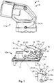
- FIG. 1 shows an electric connector assembly 1 in an unassembled state 3.
- the electric connector assembly 1 comprises an electric connector 5 and a complementary electric connector 7.
- the electric connector 5 is embodied as a socket 5a and the complementary electric connector 7 as a plug 7a.
- the electric connector 5 comprises a locking lever 9, which is held rotatably around an axis of rotation 11 in the electric connector 5.
- Figure 1 shows the locking lever 9 in an open position 13, whereas in the unassembled state 3 the locking lever 9 may be freely rotated around the axis of rotation 11 from the shown open position 13 to the locked position (not shown in Figure 1 ).
- the locking lever 9 comprises two lever legs 15 which are connected to each other by a lever base 17.
- the lever legs 15 are oriented substantially perpendicular to the axis of rotation 11, whereas the lever base 17 is substantially parallel to the axis of rotation 11.
- the lever 9 further comprises a lever handle 19 extending away from the axis of rotation 11 and two primary lock elements 21 which are embodied as pin receptacles 23 and located in the lever legs 15 distal to the lever handle 19.
- the pin receptacles 23 comprise rounded entrance edges 25 which are shown in more detail in the zoom 27.
- the rounded entrance edges 25 allow for a correct positioning of the complementary electric connector 7 with respect to the electric connector 5 by means of complementary primary lock elements 29 which are embodied as pins 31 in the embodiment of the electric connector assembly 1 shown in Figure 1 .
- the pin receptacle 23 has a convex region 33 and a concave region 35, wherein the point of the convex region 33, which is the nearest to the axis of rotation 11, is located in the distance 33a from the axis of rotation 11 and the point of the concave region 35, which is furthest away from the axis of rotation 11, is located in the distance 35a from the axis of rotation 11.
- the distance 33a is smaller than the distance 35a.
- Figure 1 furthermore shows a secondary locking member 37 with a handling member 39 and an indication member 41.
- the secondary locking member 37 is fixed to and received by the locking lever 9 along an insertion direction 38, respectively. Further details of the locking lever 9 and the secondary locking member 37 are described with reference to the following figures.
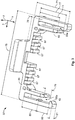
- Figures 2 and 3 show a first and a second embodiment of the inventive secondary locking member 37 prior to mounting on the electrical connector 5 (not shown).
- the secondary locking member 37 extends substantially into an x-direction and a y-direction as well as in a z-direction.
- the secondary locking member 37 is substantially U-shaped and comprises two opposing legs embodied as two outer legs 43 which are connected to a base 45 at a first end 47.
- the two outer legs 43 are substantially parallel to each other and substantially perpendicular to the base 45.
- a second end 49 of the outer legs 43 comprises a locking element 51, which is embodied as a hook 53 extending into a pocket 55 enclosed by the outer legs 43 and the base 45.
- a catch 56 is embodied as a catch member 57 extending into the pocket 55.
- the catch members 57 comprise inclined surfaces 59
- the hooks 53 comprise an inclined surface 59 facing away from the base 45 and a shoulder 61 facing towards the base 45.
- two inner legs 63 extend from the base 45 into the pocket 55 of the secondary locking member 37.
- the connection of the inner legs 63 to the base 45 is reinforced by a broadening of the inner legs 63 in a pedestal region 65.
- a sub-pocket 55a is formed between the outer leg 43 and the inner leg 63.
- the secondary locking member 37 furthermore comprises six protrusions 66 embodied as locking teeth 67, each of them extending from the base 45 into the pocket 55 of the secondary locking member 37.
- the handling member 39 is located outside the secondary locking member 37 and also extends into a direction substantially perpendicular to the base 45 and substantially perpendicular to the outer legs 43.
- the secondary locking member 37 comprises a stop edge 69, which is clearly visible in Figure 4 .
- the outer legs 43 have a leg length 71
- the inner legs 63 have an inner leg length 73
- the secondary locking member 37 has a width 75.
- An insertion length 77 is measured between the stop edge 69 and the shoulder 61 of the hook 53, and a gap width 78 between the stop edge 69 and the handling member 39.
- the first catch distance 83 is measured from the stop edge 69 to the catch member 57
- the second catch distance 85 is measured from the shoulder 61 of the outer legs 43 to the catch member 57.
- the base 45, the locking teeth 67 and the inner legs 63 have a height 79
- the outer legs 43 have, from the stop edge 69 in y-direction onwards, a leg height 81, which is smaller than the height 79.
- the lengths 71, 73, 77, the widths 75, 78, the heights 79, 81 and the distances 83, 85 are drawn in Figure 3 .
- the difference between the two embodiments of the secondary locking member 37 of Figure 2 and Figure 3 is the inner leg length 73, which is larger than the first catch distance 83 in the second embodiment ( Figure 3 ) of the secondary locking member 37, whereas in the first embodiment of the secondary locking member 37 ( Figure 2 ), the inner legs 63 do not extend in y-direction from the base 45 beyond the catch members 57.
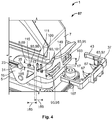
- Figure 4 shows a detailed perspective view of the electric connector assembly 1 with the electric connector 5 and the complementary electric connector 7 in the assembled state 87.
- the locking lever 9 is in a locked position 89, that is the pins 31 of the complementary electric connector 7 are received in the pin receptacles 23 of the locking lever 9 and abut the concave region 35 of the pin receptacles 23.
- the electric connector 5 and the complementary electric connector 7 are engaged in a primary lock 117.
- the locking lever 9 comprises several openings 93 located in the lever legs 15 and the lever base 17.
- the openings 93 in the lever base 17 extend partially into the lever legs 15 and are embodied as locking member receptacles 95, adapted to receive the secondary locking elements 97.
- the secondary locking elements 97 comprise the inner legs 63 and the front locking teeth 67.
- a bridge member 149 is located between the locking member receptacles 95 to increase stability of the locking lever 9.
- the openings 93 located in the lever legs 15 are embodied as a hook receptacle 99 or catch receptacles 101, wherein the locking member receptacles 95 have a first receptacle height 103, which is larger than a second receptacle height 105 of the hook receptacles and catch receptacles 99, 101.
- the first receptacle height 103 is on the same order of magnitude as the height 79 of the base 45 and the inner legs 65, that is the inner legs 65 as well as the locking teeth 67 may be inserted into the locking member receptacles 95 without abutting the outside of the locking lever 9.
- the play between the locking member receptacles 95 and the base 45, respectively between the locking member receptacles 95 and the inner legs 63, is as small as possible to prevent unwanted relative movements between the locking lever 9 and the secondary locking member 37 and as large as necessary to prevent degradation of the guidance of the secondary locking member 37 in the locking lever 9.
- the secondary locking member 37 comprises an indication member 107 located on the side of the outer leg 43 facing away from the pocket 55.
- the locking lever 9 comprises a first indicator mark 109 and a second indicator mark 111.
- the distance between the first indicator mark 109 and a first receptacle wall 113 equals approximately the distance between the second indicator mark 111 and a second receptacle wall 115, whereas both distances equal approximately the second catch distance 85 (see Figure 3 ).
- Figures 5a-5c illustrate a sequence of plugging the electric connector 5 to the complementary electric connector 7 and engagement of the primary 117 and the secondary lock 119.
- the electric connector assembly 1 (shown in Figures 5a-5c ) is in the assembled state 87.
- the pin 31 is located in the entrance of the pin receptacle 23 and upon exertion of a force F on the lever handle 19.
- the locking lever 9 rotates around the axis of rotation 11 counter-clockwise until the locked position 89 of the locking lever 9 is reached.
- FIG. 5b This is shown in Figure 5b , illustrating the electric connector assembly 1 in the assembled state 87 and with the primary lock 117 engaged.
- the pin receptacle 23 was rotated together with the locking lever 9 and received the pin 31 in a pin receptacle region distal to the entrance of the pin receptacle 23.
- the secondary locking member 37 remained in the first position 123 and simply moved along with the locking lever 9.
- the situation shown in Figure 5b corresponds to an electric connector assembly 1 of the state of the art.
- certain circumstances may result in a movement of the locking lever 9 from the locked position 89 to the open position 13 by chance. This movement is initiated by a possible force Fp, indicated by a dashed arrow.
- the indication member 107 is located next to the second indicator mark 111.
- the handling member 39 In the second position, the handling member 39 is located closer to the locking lever 9 and defines a tool insertion space 127 located between the handling member 39 and the locking lever 9.
- the tool insertion space 127 is just large enough to allow insertion of the blade of a screw driver, to pry apart the secondary locking member 37 from the locking lever 9
- the secondary lock 119 secures the primary lock 117 by preventing a movement of the locking lever 9 from the locked position 89 to the open position 13 and furthermore locks the electric connector 5 to the complementary electric connector 7.
- the embodiment of the lever handle 19 shown in Figures 5a-5c extends away from a volume 129 between the legs of the lever 15 (see Figure 1 ).
- the lever handle 19 therefore partially shields the access to the handling member 39 of the secondary locking member 39 in both the first position 123 and the second position 125.
- Figure 6 shows the electric connector assembly 1 in the assembled state 87 and with the primary and secondary lock 117, 119 engaged.
- the detailed view is partially cut to illustrate the abutment of the secondary locking members 97 embodied as locking teeth 67 with a complementary locking member 131 of the complementary electric connector 7, whereas the complementary locking member 131 is embodied as a stepped surface 133 in the housing 135 of the complementary electric connector 7.
- the overlap between the complementary locking member 131, embodied as stepped surface 133, with the secondary locking member 37 may be quite small, in the order of 1 mm, in order to achieve a reliable locking effect.
- Figure 6 shows that the stepped surface 133 is embodied circumferentially around the housing 135.
- the locking teeth 67 are extending through the locking member receptacles 95 into the volume 129 between the lever legs 15.
- the locking teeth 67 therefore abut the stepped surface 133 and block a movement of the complementary electric connector 7 away from the electric connector 5.
- Figures 7a, 7b , 8a, 8b show the electric connector assembly 1 in the assembled state 87 with engaged primary lock 117 in a cut along a line A-A, which is shown in Figure 5c .
- Figures 7a, 7b show the secondary locking member 37 and the locking lever 9 in a first embodiment and Figures 8a, 8b show the secondary locking member 37 and the locking lever 9 in a second embodiment.
- the locking lever 9 is made of a stiff material as for instance a metal, which does not allow a deflection.
- the secondary locking member 37 is preferably made of a resin material.
- the second embodiment of the secondary locking member 37 and the locking lever 9 is preferred if those elements 7, 37 are made of a deflectable material as for instance a polymer, which allows a deflection of parts of both elements.
- the secondary locking member 37 further comprises a bridge member 149 which increases the stability of the locking lever 9 in the regions of the locking member receptacles 95 (see Figure 4 ).
- the secondary locking member 37 is in the first position 123, in which the catch member 57 is engaged in a positive lock with the catch receptacle 101 which is located farther away from the axis of rotation 11.
- the hook 53 is engaged in the hook receptacle 99, wherein the shoulder 61 is located close to the first receptacle wall 113, the pins 31 are monolithically connected to the housing 135 of the complementary electric connector 7, and the volume 129 between the lever legs 15 is indicated by a dashed line.
- the inner legs 63 extend through the locking member receptacles 95 into the volume 129 between the lever legs 15, whereas the locking teeth 67 (only two of them are indicated by reference signs for the sake of visibility) do not extend into the volume 129.
- Figure 7a and 7b also show the stepped surface 133 which is located circumferentially around the housing 135 of the complementary electric connector 7.
- the inner legs 63 do not overlap or abut the stepped surface 133 in the first position 123 of the secondary locking member 37.
- Figure 7b shows the electric connector assembly 1 of Figure 7a wherein, additionally to the primary lock 117, the secondary lock 119 is engaged.
- the secondary lock 119 is engaged by moving the secondary locking member 37 into the second position 125, the second position 125 is characterized in that the inner legs 63 and the locking teeth 67 extend into the volume 129 between the lever legs 15 (indicated by the dashed line).
- the inner legs 63 as well as the locking teeth 67 overlap the stepped surface 133 of the housing 135.
- the pedestal regions 65 of the secondary locking member 37 overlap with the stepped surface 133 and thus contribute to the secondary lock 119.
- the catch member 57 In the second position 125 of the secondary locking member 37, the catch member 57 is located in the catch receptacle 101 located closer to the axis of rotation 11 and the hook 53 is shifted inside the hook receptacle 99, wherein, in the second position 125 of the secondary locking member 37, the hook 53 is closer to the second receptacle wall 115.
- the second embodiment of the locking lever 9 and the second embodiment of the secondary locking member 37, as shown in Figures 8a and 8b , are preferentially made of a flexible material as, for instance, a polymer.
- the lever thickness 137 of the second embodiment of the locking lever 9 is larger than the lever thickness 137 of the second embodiment of Figure 7a because the preferentially used material for this second embodiment is less rigid than the material used in the first embodiment ( Figures 7a and 7b ) and therefore the locking lever 9 and the secondary locking member 37 require a larger lever thickness 137 in order to maintain mechanical properties of the locking lever 9 and the secondary locking member 37.
- the inner legs 63 extend from the base 45 of the secondary locking member into the volume 129 between the lever legs 15, wherein the inner leg length 73 is larger than the first catch distance 83 (see Figure 3 ), the inner legs 63 therefore extend further towards the axis of rotation 11 than the catch members 57.
- the locking lever 9 comprises an inclined surface 59 partially facing towards the base 45 of the secondary locking member 37, the inclined surface 59 are located in transition regions 139, which are located between an abutment region 141 and a deflection region 143.
- the inner legs 63 are located in the deflection regions 143 in which the inner legs 63 are deflectable towards the lever legs 15 because of a spacing 145.
- the overlap of the inner legs 63 with the stepped surfaces 133 in an overlap region 147 may be considered as an intermediate lock 118, wherein this intermediate lock 118 may be easily disengaged by deflecting the inner legs 63 towards the lever legs 15.
- each inner leg 63 extends through the deflection region 143 and through the transition region 139 into the abutment region 141.
- the inner legs 63 As the inner legs 63 are located in the abutment regions 141, the spacing 145 between the inner legs 63 and the lever legs 15 is decreased which is shown in the zoom 27. In different embodiments of the locking lever 9 and the secondary locking member 37, the inner legs 63 may even abut the lever legs 15.
- the decreased spacing 145a prevents a deflection of the inner legs 63 towards the lever legs 15 as well as a disengagement of the secondary lock 119 prior to moving the secondary locking member 37 from the second position 125 to the first position 123.
Landscapes
- Details Of Connecting Devices For Male And Female Coupling (AREA)
Abstract
Description
- The invention relates to an electric connector with a U-shaped locking lever, the locking lever being held rotatably around an axis of rotation in the electric connector for engagement to a complementary electric connector. The invention further relates to an electric connector assembly comprising an electric connector with a U-shaped locking lever held rotatably around an axis of rotation in the electric connector from an open position to a locked position, a complementary electric connector adapted to be connected to the electric connector, wherein, in the locked position of the locking lever, the electric connector and the complementary electric connector are engaged in a primary lock.
- Such electric connectors and electric connector assemblies are known in the art and for instance described in German patent publication
DE 10 2010 002 176 B4 . Solutions of the prior art have the disadvantage that the locking lever could be opened by chance or by misuse. - One objective of the present invention is therefore to provide an electric connector and an electric connector assembly which provides a secondary lock for securing the primary lock and for preventing the electric connector assembly from unlocking by chance or by misuse.
- The electric connector of the aforementioned type solves this problem by providing the locking lever with a secondary locking member for additional engagement to the complementary electric connector, the secondary locking member being fixed to the locking lever slidably along an insertion direction, which is substantially perpendicular to the axis of rotation, into the locking lever from a first to a second position.
- The electric connector assembly of the aforementioned type solves this problem by providing the locking lever with a secondary locking member, the secondary locking member being adapted to be slid on the locking lever perpendicular to the axis of rotation into engagement with the complementary electric connector to form a secondary lock.
- Those solutions provide a secured primary lock, which may not be unlocked prior to disengaging the secondary lock, whereas the secondary lock may, in particular, not be disengaged by hand and may therefore prevent disengagement of the secondary lock by chance or by misuse.
- Another objective of the inventive electric connector and the inventive electric connector assembly may be prevention of an incomplete engagement of the electric connector to the complementary electric connector, which may not be secured by the locking lever and which may be disengaged by chance or for instance vibrations of the electric connector assembly.
- Engagement of the secondary lock between the electric connector and the complementary electric connector may only be possible after engagement of the primary lock.
- In the following, further embodiments are given that are advantageous on their own. The solutions represented by these embodiments of the invention can be combined as desired.
- In a first advantageous embodiment of the inventive electric connector the secondary locking member is U-shaped. A U-shaped secondary locking member has the advantage that the secondary locking member may be firmly fixed to the locking lever, not altering the general shape or the size of the electric connector.
- The U-shaped secondary locking member may in particular comprise two opposing longitudinal structures connected to each other by a common base, wherein the longitudinal structures are oriented substantially perpendicular to the base. The secondary locking member may comprise connection portions connecting the longitudinal structures of the secondary locking member to the base, wherein said connection portions may be embodied with a substantially rectangular edge or may be embodied as a rounding with a rounding radius of up to half the distance between the longitudinal structures of the secondary locking member.
- In a second advantageous embodiment of the inventive electric connector the secondary locking member has at least two legs which form a pocket in which at least a section of a leg of the locking lever is received. Receiving the locking lever in the pocket of the secondary locking member has the advantage that fixing the secondary locking member to the locking lever, as well as guiding the secondary locking member along the insertion direction into the locking lever, is facilitated.
- The pocket of the secondary locking member may in particular receive a section of each of the two legs of the locking lever. Such an arrangement allows for a symmetrical mounting of the secondary locking member to the locking lever preventing blocking of the secondary locking member due to its rotation with respect to the locking lever when pushed on one side.
- In another advantageous embodiment of the inventive electric connector, the at least two legs comprise an inner leg and an outer leg on the outside of the leg of the locking lever, the inner leg being shorter than the outer leg.
- The inner leg may be located on the side of the locking lever which is closer to an opposite leg of the locking lever.
- The inner leg may be located in a space between the legs of the locking lever and the outer leg on the outside of this space.
- The inner leg and the outer leg of the secondary locking member may therefore form a sub-pocket for receiving at least a portion of the wall of the locking lever, therefore allowing an easy and secure fixation, and guidance of the secondary locking member to and within the locking lever.
- In another embodiment of the inventive electric connector, it is advantageous if, in the first position, the inner leg extends parallel to and is spaced apart from the leg of the locking lever received in the pocket adjacent to this inner leg.
- The leg of the locking lever may preferentially be received in the sub-pocket adjacent to the inner leg, the sub-pocket may be formed between the inner and the outer leg.
- Such a spacing may allow the inner leg to be deflected towards the leg of the locking lever, which may be advantageous to allow for an imperfect insertion of the secondary locking member into the locking lever that is not along the insertion direction, but with an angle to the insertion direction without blocking the insertion of the secondary locking member.
- The spacing may be adapted to allow a deflection of the inner leg by up to one width of the inner leg, wherein the width is measured in the direction of deflection.
- The deflection of the inner leg may be limited by a maximum deflection of the inner leg or by an abutment of the inner leg with the leg of the locking lever. The inner leg may be attached to the base of the secondary locking member by a reinforced pedestal which may be adapted to limit the deflection of the inner leg and/or may be adapted to transfer shear forces, which are due to deflection of the inner leg, to the base of the secondary locking member.
- In another advantageous embodiment of the inventive electric connector, in the second position, the spacing between the inner leg and the leg of the locking lever is decreased with respect to the first position or the inner leg abuts the leg of the locking lever.
- If engagement of the primary lock between the electric connector and the complementary electric connector requires the deflection of the inner arm of the secondary locking member, a reduced spacing in the second position may prevent engaging the primary lock by rotating the locking lever with the secondary locking member being in the second position.
- The side of the leg of the locking lever facing towards the volume between the legs of the locking lever may comprise a chamfer, which substantially faces towards the inner leg, that is, the chamfer is tilted from the insertion direction towards the base of the secondary locking member.
- Upon moving the secondary locking member from the first position to the second position, the inner leg may pass by this chamfer or may touch the chamfer resulting in a deflection of the inner leg away from the spacing leading to an abutment between the inner leg and the leg of the locking lever.
- In another advantageous embodiment of the inventive electric connector, the inner leg protrudes into a volume between the legs of the locking lever.
- The inner leg may protrude into the volume only in the second position, or in both the first and the second position of the secondary locking member. Similarly to the at least one protrusion extending into the volume between the legs of the locking lever, the inner leg may be part of or may support the secondary lock between the electric connector and the complementary electric connector.
- In another embodiment of the inventive electric connector, it is advantageous if the outer leg is provided with a locking element that locks the secondary locking member in the first position. Such a locking element prevents an unwanted unmounting of the secondary locking member from the locking lever.
- The locking element may be embodied as a detent hook with an inclined surface, substantially facing away from the base of the secondary locking member and a shoulder being substantially oriented parallel to and facing towards the base of the secondary locking member.
- The locking lever may comprise hook receptacles adapted to slidingly receive the detent hook of the secondary locking member, the hook receptacles may comprise a first receptacle wall facing substantially in the insertion direction, thus, facing opposite to the shoulder of the detent hook of the secondary locking member installed to the locking lever.
- Abutment of the first receptacle wall of the locking lever and the shoulder of the detent hook may occur in the first position of the secondary locking member or when the secondary locking member is moved opposite to the insertion direction out of the locking lever.
- In another advantageous embodiment of the inventive electric connector, the secondary locking member has a base section extending parallel to a lever base section connecting the legs of the locking lever, the base section being provided with at least one protrusion that, at least in the second position, protrudes through at least one opening of the locking lever into the volume between the legs of the locking lever. The at least one protrusion may be a part of, or may support the secondary lock between the electric connector and the complementary electric connector.
- In the first position of the secondary locking member, the at least one protrusion may not extend into the volume between the legs of the locking lever. This embodiment has the advantage that the locking lever may be rotated around the axis of rotation without the at least one protrusion blocking this rotational movement by touching any structure located in the volume between the legs of the locking lever.
- The at least one protrusion may be embodied as a locking tooth, wherein several locking teeth may be provided symmetrically or asymmetrically along the base section of the secondary locking member.
- The at least one protrusion may be embodied as one single protrusion extending along the whole base section of the secondary locking member.
- In another embodiment of the inventive electric connector, it is advantageous if a catch is provided which locks the secondary locking member both in the first and in the second position.
- Such a catch has the advantage that the first and the second position may be clearly distinct from any intermediate position of the secondary locking member between the first and the second position.
- This catch may further comprise indication means providing a feedback to the end-user, and allowing for an indication in which position the secondary locking member is located.
- The catch may be embodied as a catch member comprising inclined surfaces, wherein the surface being located closer to the base of the secondary locking member is inclined towards this base and wherein the surface being located further from the base of the secondary locking member is inclined away from this base.
- Such a catch member may be adapted to be received in a catch receptacle which may be embodied as a hole in the leg of the locking lever. Two of such catch receptacles may be provided in the leg of the locking lever according to the first and the second position of the secondary locking member.
- In another advantageous embodiment of the inventive electric connector the secondary locking member is provided with a plate-like handling member, which protrudes from the locking lever in a direction facing away from the volume between the legs of the locking lever and in that, in the second position, the handling member comprises a section which is spaced apart from the locking lever and thus defines a tool insertion space.
- The plate-like handling member may be adapted to transfer a handling force exerted on the handling member to the secondary locking member. The handling member may preferentially be located in a central portion of the base of the secondary locking member in order to allow for a symmetric exertion of the handling force to the secondary locking member.
- The locking lever may comprise a lever handle also extending substantially away from the volume between the legs of the locking lever, whereas this lever handle may at least partially prevent accessing the handling member.
- The tool insertion space may be adapted to receive a release tool such as a screw driver in order to move the secondary locking member from the second position to the first position. The lock of the catch member with the catch receptacle may therefore be sufficiently strong to prevent a movement of the secondary locking member from the second position to the first position by hand.
- The inventive electric connector assembly of the aforementioned type may be adapted to allow a movement of the secondary locking member from the first and second position only in the locked position of the locking lever that is after engagement of the electric connector and the complementary electric connector in the primary lock.
- In a first embodiment of the electric connector assembly, the secondary locking member engages with a complementary locking member of the complementary electric connector, the complementary locking member being one of a stepped surface, a protrusion or a recess of the complementary electric connector located in the volume between the legs of the locking lever.
- The complementary locking member may be embodied as an at least partially circumferential edge which may be present per se at the complementary electric connector.
- The complementary locking member may be located in the volume between the legs of the locking lever in both, the open and the locked position of the locking lever, but may as well be only located in said volume when the locking lever is moved to the locked position.
- The overlap between the complementary locking member, which may be embodied as a stepped surface, may be quite small, in the order of 1 mm, in order to achieve a reliable locking effect. Therefore a compact design may be combined with an efficient locking effect.
- It is conceivable that the locking lever may only be moved from the open to the locked position with the secondary locking member in the first position, whereas when the secondary locking member is in the second position, movement of the locking lever from the open to the closed position may be prevented.
- When the electric connector and the complementary electric connector are plugged together and the locking lever is in the open position, a translation of the secondary locking member from the first position to the second position may be prevented by the complementary electric connector.
- A procedure for engaging the primary and the secondary lock between the electric connector and the complementary electric connector may comprise the following steps:
- (a) if not already in the open position, the locking lever is moved to the open position, the secondary locking member is installed to the locking lever and is in the first position;
- (b) the electric connector and the complementary electric connector are plugged together and subsequent to completion of plugging them together, the locking lever is moved from the open position to the locked position, whereas the secondary locking member remains in the first position and is moved along with the locking lever;
- (c) When the locking lever has reached the locked position, that is upon completion of engagement between the electric connector and the complementary electric connector in the primary lock, the secondary locking member may be translated from the first position to the second position, wherein when reaching the second position, the electric connector assembly engages the additional secondary lock between the electrical connector and the complementary electrical connector.
- When moving the locking lever from the open position to the locked position, the inner legs and the at least one protrusion extending from the base of the secondary locking member may already extend into the volume between the legs of the locking lever, whereas a spacing between the complementary electric connector and the locking lever may allow the inner legs and/or the at least one protrusion to extend into the volume between the legs of the locking lever without touching the complementary electric connector when the locking lever is moved from the open position to the locked position.
- After completion of the primary lock, pushing the handling member may insert the inner legs and/or the at least one protrusion into the volume or further into the volume between the legs of the locking lever.
- During this insertion the inner legs and/or the at least one protrusion may be moved or slid along the complementary locking member of the complementary electric connector in an overlapping manner, thus engaging a positive lock between the complementary locking member and the secondary locking member. The complementary locking member abuts the inner legs and/or the at least one protrusion such that a movement of the locking lever from the locked position to the open position is blocked.
- Several abutment regions between the complementary locking member and the secondary locking member are advantageous as they may allow distribution of a force exerted on the locking lever in the direction of the open position into the complementary electric connector, into the locking lever and into the secondary locking member.
- In a second advantageous embodiment of the inventive electrical connector assembly the at least one inner leg of the secondary locking member is adapted to be deflected by the complementary electric connector towards the locking lever in the first position of the secondary locking member and in that the locking lever is adapted to be moved into engagement with the complementary electric connector with the secondary locking member fixed to the locking lever in the first position.
- Such a spacing may be advantageous if the secondary locking member is mounted to the locking lever in a direction with an angle to the insertion direction. In such a case, insertion of the secondary locking member is not blocked by abutment of the legs of the secondary locking member with the locking lever.
- In a third advantageous embodiment of the inventive electrical connector assembly, the secondary locking member is snapped over the complementary locking member of the complementary electric connector when the electric connector is engaged in the primary lock with the complementary electric connector.
- In particular the at least one inner leg of the secondary locking member may be snapped over the complementary locking member. When the electric connector is being engaged in the primary lock with the complementary electric connector, in particular the at least one inner leg of the secondary locking member may be slid along a housing of the complementary electric connector, wherein prior to completion of the primary lock between the electric connector and the complementary electric connector the at least one inner leg of the secondary locking member may snap over the complementary locking member.
- As a deflection of the inner leg towards the locking lever is possible in the first position of the secondary locking member, rotation of the locking lever from the open to the locked position may be possible even if the inner leg touches the complementary electric connector in the first position of the secondary locking member.
- This abutment may cause a deflection of the inner leg towards the leg of the locking lever, whereas the deflected inner leg may be slidably moved together with the locking lever rotated from the open position to the locked position.
- During this movement, the inner leg remains deflected and slides above the complementary electric connector until reaching the complementary locking member of the complementary electric connector.
- When reaching the complementary locking member, the inner leg may return to its relaxed state, that is the non-deflected state by a snapping movement over said complementary locking member. Thus, the state reached after this snapping movement may be understood as an intermediate lock occurring between the primary lock and the secondary lock.
- The snapping movement furthermore yields the advantage that an acoustic and/or haptic feedback may be provided to the end-user, indicating completion of engagement in the primary lock.
- For sliding the secondary locking member from the first position to the second position, an insertion distance has to be overcome. This insertion distance determines the overlap of the inner leg and/or the at least one protrusion with the complementary locking member of the complementary electric connector.
- On the one hand, a larger overlap will result in a higher strength of the secondary lock. On the other hand, a larger overlap requires a larger insertion distance. This compromise may be overcome at least partially by providing a deflectable inner leg canceling the direct proportionality between the overlap and the insertion distance.
- After reaching the locked position of the locking lever, the secondary locking member may, as described above, be moved from the first position to the second position with the inner leg remaining in the relaxed state.
- In the second position of the secondary locking member, the spacing between the inner leg and the leg of the locking lever may be decreased or the inner leg may even abut the leg of the locking lever, thus preventing a deflection of the inner leg towards the leg of the locking lever.
- This may ensure that once the secondary locking member has reached the second position, the deflection of the inner arm is blocked and the primary and secondary lock may not be disengaged prior to moving the secondary locking member from the second position to the first position.
- The movement of the secondary locking member from the second position to the first position may be performed by the end-user by means of a release tool, for instance a screw driver, inserted into the tool insertion space defined by a section of the handling member which is spaced apart from the locking lever.
- Subsequent to moving the second locking member from the second position to the first position, rotation of the locking lever from the locked position to the open position is possible, wherein prior to this movement the inner leg is deflected towards the leg of the locking lever and wherein during this movement the inner leg slides at least partially along the complementary electric connector.
- In the following, the invention will be described in more detail by way of example hereinafter using advantageous embodiments and with reference to the accompanying drawings. The individual features of the described embodiments may be implemented independently of each other or may be omitted if the technical effect of the omitted feature is not relevant. Equal technical features and technical features with similar functions or technical effects illustrated in the drawings are provided with equal reference signs. Redundant parts of the description related to equal elements illustrated in different drawings are omitted.
- The figures show:
- Fig. 1
- a perspective view of the electric connector assembly;
- Fig. 2
- a perspective view of a first embodiment of the secondary locking member;
- Fig. 3
- a perspective view of a second embodiment of the secondary locking member;
- Fig. 4
- a perspective detailed view of the electric connector assembly with an engaged primary lock and unmounted secondary locking member;
- Fig. 5a
- a perspective view of the electric connector assembly with the locking lever in the open position;
- Fig. 5b
- a perspective view of the electric connector assembly with the locking lever in the locked position;
- Fig. 5c
- a perspective view of the electric connector assembly with engaged primary and secondary lock;
- Fig. 6
- a partially cut perspective view of the electric connector assembly of
Figure 5c ; - Fig. 7a/7b
- sectional views of the electric connector assembly with the secondary locking member of
Figure 2 ; and - Fig 8a/8b
- sectional views of the electric connector assembly with the secondary locking member of
Figure 3 . -
Figure 1 shows anelectric connector assembly 1 in anunassembled state 3. Theelectric connector assembly 1 comprises anelectric connector 5 and a complementaryelectric connector 7. - In the
electric connector assembly 1 shown inFigure 1 , theelectric connector 5 is embodied as a socket 5a and the complementaryelectric connector 7 as a plug 7a. - The
electric connector 5 comprises a lockinglever 9, which is held rotatably around an axis ofrotation 11 in theelectric connector 5.Figure 1 shows the lockinglever 9 in an open position 13, whereas in theunassembled state 3 the lockinglever 9 may be freely rotated around the axis ofrotation 11 from the shown open position 13 to the locked position (not shown inFigure 1 ). - The locking
lever 9 comprises twolever legs 15 which are connected to each other by alever base 17. Thelever legs 15 are oriented substantially perpendicular to the axis ofrotation 11, whereas thelever base 17 is substantially parallel to the axis ofrotation 11. - The
lever 9 further comprises alever handle 19 extending away from the axis ofrotation 11 and two primary lock elements 21 which are embodied aspin receptacles 23 and located in thelever legs 15 distal to thelever handle 19. - The pin receptacles 23 comprise rounded entrance edges 25 which are shown in more detail in the
zoom 27. The rounded entrance edges 25 allow for a correct positioning of the complementaryelectric connector 7 with respect to theelectric connector 5 by means of complementary primary lock elements 29 which are embodied aspins 31 in the embodiment of theelectric connector assembly 1 shown inFigure 1 . - The
pin receptacle 23 has aconvex region 33 and aconcave region 35, wherein the point of theconvex region 33, which is the nearest to the axis ofrotation 11, is located in thedistance 33a from the axis ofrotation 11 and the point of theconcave region 35, which is furthest away from the axis ofrotation 11, is located in thedistance 35a from the axis ofrotation 11. Thedistance 33a is smaller than thedistance 35a. -
Figure 1 furthermore shows asecondary locking member 37 with a handlingmember 39 and an indication member 41. Thesecondary locking member 37 is fixed to and received by the lockinglever 9 along aninsertion direction 38, respectively. Further details of the lockinglever 9 and thesecondary locking member 37 are described with reference to the following figures. -
Figures 2 and3 show a first and a second embodiment of the inventivesecondary locking member 37 prior to mounting on the electrical connector 5 (not shown). - The
secondary locking member 37 extends substantially into an x-direction and a y-direction as well as in a z-direction. - The
secondary locking member 37 is substantially U-shaped and comprises two opposing legs embodied as twoouter legs 43 which are connected to a base 45 at afirst end 47. The twoouter legs 43 are substantially parallel to each other and substantially perpendicular to thebase 45. - A
second end 49 of theouter legs 43 comprises a lockingelement 51, which is embodied as ahook 53 extending into apocket 55 enclosed by theouter legs 43 and thebase 45. - Approximately in the center of both
outer legs 43, a catch 56 is embodied as acatch member 57 extending into thepocket 55. In a direction perpendicular to thebase 45, thecatch members 57 compriseinclined surfaces 59, whereas thehooks 53 comprise aninclined surface 59 facing away from thebase 45 and ashoulder 61 facing towards thebase 45. - Parallel to the
outer legs 43, twoinner legs 63 extend from the base 45 into thepocket 55 of thesecondary locking member 37. The connection of theinner legs 63 to thebase 45 is reinforced by a broadening of theinner legs 63 in apedestal region 65. A sub-pocket 55a is formed between theouter leg 43 and theinner leg 63. - The
secondary locking member 37 furthermore comprises six protrusions 66 embodied as lockingteeth 67, each of them extending from the base 45 into thepocket 55 of thesecondary locking member 37. - The handling
member 39 is located outside thesecondary locking member 37 and also extends into a direction substantially perpendicular to thebase 45 and substantially perpendicular to the outer legs 43.Thesecondary locking member 37 comprises astop edge 69, which is clearly visible inFigure 4 . - The
outer legs 43 have aleg length 71, theinner legs 63 have aninner leg length 73 and thesecondary locking member 37 has awidth 75. Aninsertion length 77 is measured between thestop edge 69 and theshoulder 61 of thehook 53, and agap width 78 between thestop edge 69 and the handlingmember 39. Thefirst catch distance 83 is measured from thestop edge 69 to thecatch member 57, thesecond catch distance 85 is measured from theshoulder 61 of theouter legs 43 to thecatch member 57. Thebase 45, the lockingteeth 67 and theinner legs 63 have aheight 79, whereas theouter legs 43 have, from thestop edge 69 in y-direction onwards, aleg height 81, which is smaller than theheight 79. For reasons of visibility thelengths widths heights distances Figure 3 . - The difference between the two embodiments of the
secondary locking member 37 ofFigure 2 andFigure 3 is theinner leg length 73, which is larger than thefirst catch distance 83 in the second embodiment (Figure 3 ) of thesecondary locking member 37, whereas in the first embodiment of the secondary locking member 37 (Figure 2 ), theinner legs 63 do not extend in y-direction from thebase 45 beyond thecatch members 57. -
Figure 4 shows a detailed perspective view of theelectric connector assembly 1 with theelectric connector 5 and the complementaryelectric connector 7 in the assembledstate 87. - The locking
lever 9 is in a locked position 89, that is thepins 31 of the complementaryelectric connector 7 are received in thepin receptacles 23 of the lockinglever 9 and abut theconcave region 35 of thepin receptacles 23. Theelectric connector 5 and the complementaryelectric connector 7 are engaged in aprimary lock 117. - In
Figure 4 , thesecondary locking member 37 is not mounted to the lockinglever 9, therefore showing technical features of the lockinglever 9 which where hidden in the previous figures. - The locking
lever 9 comprises several openings 93 located in thelever legs 15 and thelever base 17. The openings 93 in thelever base 17 extend partially into thelever legs 15 and are embodied as lockingmember receptacles 95, adapted to receive the secondary locking elements 97. The secondary locking elements 97 comprise theinner legs 63 and the front lockingteeth 67. Abridge member 149 is located between the lockingmember receptacles 95 to increase stability of the lockinglever 9. - The openings 93 located in the
lever legs 15 are embodied as ahook receptacle 99 or catchreceptacles 101, wherein the lockingmember receptacles 95 have afirst receptacle height 103, which is larger than asecond receptacle height 105 of the hook receptacles and catchreceptacles - The
first receptacle height 103 is on the same order of magnitude as theheight 79 of thebase 45 and theinner legs 65, that is theinner legs 65 as well as the lockingteeth 67 may be inserted into the lockingmember receptacles 95 without abutting the outside of the lockinglever 9. - Furthermore, it is advantageous if the play between the locking
member receptacles 95 and thebase 45, respectively between the lockingmember receptacles 95 and theinner legs 63, is as small as possible to prevent unwanted relative movements between the lockinglever 9 and thesecondary locking member 37 and as large as necessary to prevent degradation of the guidance of thesecondary locking member 37 in the lockinglever 9. - The
secondary locking member 37 comprises anindication member 107 located on the side of theouter leg 43 facing away from thepocket 55. The lockinglever 9 comprises afirst indicator mark 109 and asecond indicator mark 111. - The distance between the
first indicator mark 109 and afirst receptacle wall 113 equals approximately the distance between thesecond indicator mark 111 and asecond receptacle wall 115, whereas both distances equal approximately the second catch distance 85 (seeFigure 3 ). -
Figures 5a-5c illustrate a sequence of plugging theelectric connector 5 to the complementaryelectric connector 7 and engagement of the primary 117 and thesecondary lock 119. The electric connector assembly 1 (shown inFigures 5a-5c ) is in the assembledstate 87. - In
Figure 5a theelectric connector assembly 1 is in the assembledstate 87, but as no lock is engaged yet, it is also in theunlocked state 121. The lockinglever 9 is in the open position 13 and thesecondary locking member 37 is in a first position 123 which is indicated by theindication member 107 located next to thefirst indicator mark 109. - The
pin 31 is located in the entrance of thepin receptacle 23 and upon exertion of a force F on thelever handle 19. The lockinglever 9 rotates around the axis ofrotation 11 counter-clockwise until the locked position 89 of the lockinglever 9 is reached. - This is shown in
Figure 5b , illustrating theelectric connector assembly 1 in the assembledstate 87 and with theprimary lock 117 engaged. Thepin receptacle 23 was rotated together with the lockinglever 9 and received thepin 31 in a pin receptacle region distal to the entrance of thepin receptacle 23. Thesecondary locking member 37 remained in the first position 123 and simply moved along with the lockinglever 9. - Without the further step explained in the following with reference to
Figure 5c , the situation shown inFigure 5b corresponds to anelectric connector assembly 1 of the state of the art. Although being engaged in aprimary lock 117, certain circumstances (accidentally touching the lockinglever 9, dropping of a tool) may result in a movement of the lockinglever 9 from the locked position 89 to the open position 13 by chance. This movement is initiated by a possible force Fp, indicated by a dashed arrow. - In order to avoid that the exertion of the possible force Fp on the lever handle 19 of the locking
lever 9 results in moving the lockinglever 9 from the locked position 89 to the open position 13, thesecondary locking member 37 is moved from the first position 123 (Figure 5b ) to the second position 125, which is shown inFigure 5c . - By moving the
secondary locking member 37 from the first position 123 to the second position 125, thesecondary lock 119 of theelectric connector assembly 1 is engaged. - In the second position 125, the
indication member 107 is located next to thesecond indicator mark 111. - In the second position, the handling
member 39 is located closer to the lockinglever 9 and defines atool insertion space 127 located between the handlingmember 39 and the lockinglever 9. Thetool insertion space 127 is just large enough to allow insertion of the blade of a screw driver, to pry apart thesecondary locking member 37 from the lockinglever 9 - The
secondary lock 119 secures theprimary lock 117 by preventing a movement of the lockinglever 9 from the locked position 89 to the open position 13 and furthermore locks theelectric connector 5 to the complementaryelectric connector 7. - The embodiment of the lever handle 19 shown in
Figures 5a-5c extends away from avolume 129 between the legs of the lever 15 (seeFigure 1 ). The lever handle 19 therefore partially shields the access to the handlingmember 39 of thesecondary locking member 39 in both the first position 123 and the second position 125. -
Figure 6 shows theelectric connector assembly 1 in the assembledstate 87 and with the primary andsecondary lock teeth 67 with a complementary locking member 131 of the complementaryelectric connector 7, whereas the complementary locking member 131 is embodied as a steppedsurface 133 in thehousing 135 of the complementaryelectric connector 7. The overlap between the complementary locking member 131, embodied as steppedsurface 133, with thesecondary locking member 37 may be quite small, in the order of 1 mm, in order to achieve a reliable locking effect. -
Figure 6 shows that the steppedsurface 133 is embodied circumferentially around thehousing 135. - As the
secondary locking member 37 is in the second position 125, the lockingteeth 67 are extending through the lockingmember receptacles 95 into thevolume 129 between thelever legs 15. The lockingteeth 67 therefore abut the steppedsurface 133 and block a movement of the complementaryelectric connector 7 away from theelectric connector 5. -
Figures 7a, 7b ,8a, 8b show theelectric connector assembly 1 in the assembledstate 87 with engagedprimary lock 117 in a cut along a line A-A, which is shown inFigure 5c .Figures 7a, 7b show thesecondary locking member 37 and the lockinglever 9 in a first embodiment andFigures 8a, 8b show thesecondary locking member 37 and the lockinglever 9 in a second embodiment. - In the first embodiment of the
secondary locking member 37 and the lockinglever 9 it is preferred if the lockinglever 9 is made of a stiff material as for instance a metal, which does not allow a deflection. thesecondary locking member 37 is preferably made of a resin material. - The second embodiment of the
secondary locking member 37 and the lockinglever 9 is preferred if thoseelements - The
secondary locking member 37 further comprises abridge member 149 which increases the stability of the lockinglever 9 in the regions of the locking member receptacles 95 (seeFigure 4 ). - In
Figure 7a , thesecondary locking member 37 is in the first position 123, in which thecatch member 57 is engaged in a positive lock with thecatch receptacle 101 which is located farther away from the axis ofrotation 11. - The
hook 53 is engaged in thehook receptacle 99, wherein theshoulder 61 is located close to thefirst receptacle wall 113, thepins 31 are monolithically connected to thehousing 135 of the complementaryelectric connector 7, and thevolume 129 between thelever legs 15 is indicated by a dashed line. - In the first position 123 of the
secondary locking member 37, theinner legs 63 extend through the lockingmember receptacles 95 into thevolume 129 between thelever legs 15, whereas the locking teeth 67 (only two of them are indicated by reference signs for the sake of visibility) do not extend into thevolume 129. -
Figure 7a and 7b also show the steppedsurface 133 which is located circumferentially around thehousing 135 of the complementaryelectric connector 7. Theinner legs 63 do not overlap or abut the steppedsurface 133 in the first position 123 of thesecondary locking member 37. - Therefore, movement of the locking
lever 9 from the open 13 to the locked position 89 (not shown) is possible without thesecondary locking member 37 touching the complementaryelectric connector 7. -
Figure 7b shows theelectric connector assembly 1 ofFigure 7a wherein, additionally to theprimary lock 117, thesecondary lock 119 is engaged. Thesecondary lock 119 is engaged by moving thesecondary locking member 37 into the second position 125, the second position 125 is characterized in that theinner legs 63 and the lockingteeth 67 extend into thevolume 129 between the lever legs 15 (indicated by the dashed line). - Furthermore, in the second position 125 of the
secondary locking member 37, theinner legs 63 as well as the lockingteeth 67 overlap the steppedsurface 133 of thehousing 135. Also, thepedestal regions 65 of thesecondary locking member 37 overlap with the steppedsurface 133 and thus contribute to thesecondary lock 119. A movement of theinner legs 63 and/or the lockingteeth 67 in a direction into the drawing plane, respectively a movement of thehousing 135 in a direction out of the drawing plane, is blocked by the abutment of theinner legs 63 and the lockingteeth 67 with the steppedsurface 133. - In the second position 125 of the
secondary locking member 37, thecatch member 57 is located in thecatch receptacle 101 located closer to the axis ofrotation 11 and thehook 53 is shifted inside thehook receptacle 99, wherein, in the second position 125 of thesecondary locking member 37, thehook 53 is closer to thesecond receptacle wall 115. - The second embodiment of the locking
lever 9 and the second embodiment of thesecondary locking member 37, as shown inFigures 8a and 8b , are preferentially made of a flexible material as, for instance, a polymer. - In comparison to
Figures 7a and 7b , thelever thickness 137 of the second embodiment of the lockinglever 9 is larger than thelever thickness 137 of the second embodiment ofFigure 7a because the preferentially used material for this second embodiment is less rigid than the material used in the first embodiment (Figures 7a and 7b ) and therefore the lockinglever 9 and thesecondary locking member 37 require alarger lever thickness 137 in order to maintain mechanical properties of the lockinglever 9 and thesecondary locking member 37. - The
inner legs 63 extend from thebase 45 of the secondary locking member into thevolume 129 between thelever legs 15, wherein theinner leg length 73 is larger than the first catch distance 83 (seeFigure 3 ), theinner legs 63 therefore extend further towards the axis ofrotation 11 than thecatch members 57. - In the first position 123 of the
secondary locking member 37 shown inFigure 8a , theinner legs 63 overlap the steppedsurface 133 of thehousing 135 of the complementaryelectric connector 7, whereas the lockingteeth 67 do not extend into thevolume 129 between thelever legs 15. - The locking
lever 9 comprises aninclined surface 59 partially facing towards thebase 45 of thesecondary locking member 37, theinclined surface 59 are located intransition regions 139, which are located between anabutment region 141 and adeflection region 143. - In
Figure 8a , theinner legs 63 are located in thedeflection regions 143 in which theinner legs 63 are deflectable towards thelever legs 15 because of aspacing 145. - The overlap of the
inner legs 63 with the steppedsurfaces 133 in an overlap region 147 may be considered as an intermediate lock 118, wherein this intermediate lock 118 may be easily disengaged by deflecting theinner legs 63 towards thelever legs 15. - In
Figure 8b , thesecondary locking member 37 is shown in the second position 125, in which the lockingteeth 67, thepedestal regions 65 and theinner legs 63 overlap the steppedsurface 133 of thehousing 135, engaging theelectric connector 5 and the complementaryelectric connector 7 in thesecondary lock 119. - By insertion of the
secondary locking member 37 further into thevolume 129 between thelegs 15 of the lockinglever 9, eachinner leg 63 extends through thedeflection region 143 and through thetransition region 139 into theabutment region 141. - As the
inner legs 63 are located in theabutment regions 141, the spacing 145 between theinner legs 63 and thelever legs 15 is decreased which is shown in thezoom 27. In different embodiments of the lockinglever 9 and thesecondary locking member 37, theinner legs 63 may even abut thelever legs 15. - The decreased spacing 145a prevents a deflection of the
inner legs 63 towards thelever legs 15 as well as a disengagement of thesecondary lock 119 prior to moving thesecondary locking member 37 from the second position 125 to the first position 123. - Further features and/or technical effects of or between the
housing 135, the lockinglever 9, and thesecondary locking member 37 related to thecatch members 57 or thehooks 53 are similar to those features and/or technical effect described inFigures 7a and 7b . -
- 1
- electric connector assembly
- 3
- unassembled state
- 5
- electric connector
- 5a
- socket
- 7
- complementary electric connector
- 7a
- plug
- 9
- locking lever
- 11
- axis of rotation
- 13
- open position
- 15
- lever leg
- 17
- lever base
- 19
- lever handle
- 21
- primary lock elements
- 23
- pin receptacle
- 25
- entrance edge
- 27
- zoom
- 29
- complementary primary lock element
- 31
- pin
- 33
- convex region
- 35
- concave region
- 37
- secondary locking member
- 38
- insertion direction
- 39
- handling member
- 41
- indication member
- 43
- outer leg
- 45
- base
- 47
- first end
- 49
- second end
- 51
- locking element
- 53
- hook
- 55
- 55a
- sub-pocket
- 56
- catch
- 57
- catch member
- 59
- inclined surface
- 61
- shoulder
- 63
- inner leg
- 65
- pedestal region
- 66
- protrusion
- 67
- locking tooth
- 69
- stop edge
- 71
- leg length
- 73
- inner leg length
- 75
- width
- 77
- insertion length
- 78
- gap width
- 79
- height
- 81
- leg height
- 83
- first catch distance
- 85
- second catch distance
- 87
- assembled state
- 89
- locked position
- 93
- opening
- 95
- locking member receptacle
- 97
- secondary locking members
- 99
- hook receptacle
- 101
- catch receptacle
- 103
- first receptacle height
- 105
- second receptacle height
- 107
- indication member
- 109
- first indicator mark
- 111
- second indicator mark
- 113
- first receptacle wall
- 115
- second receptacle wall
- 117
- primary lock
- 118
- intermediate lock
- 119
- secondary lock
- 121
- unlocked state
- 123
- first position
- 125
- second position
- 127
- tool insertion space
- 129
- volume between the lever legs
- 131
- complementary locking member
- 133
- stepped surface
- 135
- housing
- 137
- lever thickness
- 139
- transition region
- 141
- abutment region
- 143
- deflection region
- 145
- spacing
- 145a
- decreased spacing
- 147
- overlap region
- 149
- bridge member
- F
- force
- Fp
- possible force
- x
- x-direction
- y
- y-direction
- z
- z-direction
Claims (15)
- Electric connector (5) with a U-shaped locking lever (9), the locking lever (9) being held rotatably around an axis of rotation (11) in the electric connector (5) for engagement to a complementary electric connector (7), characterized in that the locking lever (9) is provided with a secondary locking member (37) for additional engagement to the complementary electric connector (7), the secondary locking member (37) being fixed to the locking lever (9) slidably along an insertion direction (38), which is substantially perpendicular to the axis of rotation (11), into the locking lever (9) from a first (123) to a second position (125).
- Electric connector (5) according to claim 1, characterized in that the secondary locking member (37) is U-shaped.
- Electric connector (5) according to claim 1 or 2, characterized in that the secondary locking member (37) has at least two legs (43, 63) which form a pocket (55, 55a) in which at least a section of a leg (15) of the locking lever (9) is received.
- Electric connector (5) according to claim 3, characterized in that the at least two legs (43, 63) comprise an inner leg (63) and an outer leg (43) on the outside of the leg (15) of the locking lever (9), the inner leg (63) being shorter than the outer leg (43).
- Electric connector (5) according to claim 4, characterized in that, in the first position (123), the inner leg (63) extends parallel to and is spaced apart from the leg (15) of the locking lever (9) received in the pocket (55, 55a) adjacent to this inner leg (63).
- Electric connector (5) according to claim 5, characterized in that in the second position (125) the spacing (145) between the inner leg (63) and the leg (15) of the locking lever (9) is decreased with respect to the first position (123) or the inner leg (63) abuts the leg (15) of the locking lever (9).
- Electric connector (5) according to any one of claims 4 to 6, characterized in that the inner leg (63) protrudes into a volume (129) between the legs (15) of the locking lever (9).
- Electric connector (5) according to any one of claims 4 to 7, characterized in that the outer leg (43) is provided with a locking element (51) that locks the secondary locking member (37) in the first position (123).
- Electric connector (5) according to any one of claims 1 to 8, characterized in that the secondary locking member (37) has a base section (45) extending parallel to a lever base section (17) connecting the legs (15) of the locking lever (9), the base section (45) being provided with at least one protrusion (66) that, at least in the second position (125), protrudes through at least one opening (93) of the locking lever (9) into the volume (129) between the legs (15) of the locking lever (9).
- Electric connector (5) according to any one of claims 1 to 9, characterized in that a catch (56) is provided which locks the secondary locking member (37) both in the first (123) and in the second position (125).
- Electric connector (5) according to any one of claims 1 to 10, characterized in that the secondary locking member (37) is provided with a plate-like handling member (39), which protrudes from the locking lever (9) in a direction facing away from the volume (129) between the legs (15) of the locking lever (9) and in that, in the second position (125), the handling member (39) comprises a section which is spaced apart from the locking lever (9) and thus defines a tool insertion space (127).
- Electric connector assembly (1) comprising an electric connector (5) with a U-shaped locking lever (9) held rotatably around an axis of rotation (11) in the electric connector (5) from an open position (13) to a locked position (89), a complementary electric connector (7), adapted to be connected to the electric connector (5), wherein, in the locked position (89) of the locking lever (9), the electric connector (5) and the complementary electric connector (7) are engaged in a primary lock (117), characterized in that the locking lever (9) is provided with a secondary locking member (37), the secondary locking member (37) being adapted to be slid on the locking lever (9) perpendicular to the axis of rotation (11) into engagement with the complementary electric connector (7) to form a secondary lock (119).
- Electric connector assembly (1) according to claim 12, characterized in that the secondary locking member (37) is adapted to engage a complementary locking member (131) of the complementary electric connector (7), the complementary locking member (131) being one of a stepped surface (133), a protrusion (64) or a recess of the complementary electric connector (7) located in a volume (129) between legs (15) of the locking lever (9).
- Electric connector assembly (1) according to claim 12 or 13, characterized in that the at least one inner leg (63) of the secondary locking member (37) is adapted to be deflected by the complementary electric connector (7) towards the locking lever (9) in the first position (123) of the secondary locking member (37) and in that the locking lever (9) is adapted to be moved into engagement with the complementary electric connector (7) with the secondary locking member (37) fixed to the locking lever (9) in the first position (123).
- Electric connector assembly (1) according to claim 13 or 14, characterized in that the secondary locking member (37) is snapped over the complementary locking member (131) of the complementary electric connector (7) when the electric connector (5) is being engaged in the primary lock (117) with the complementary electric connector (7).
Applications Claiming Priority (1)
| Application Number | Priority Date | Filing Date | Title |
|---|---|---|---|
| DE102015223113 | 2015-11-23 |
Publications (2)
| Publication Number | Publication Date |
|---|---|
| EP3171462A1 true EP3171462A1 (en) | 2017-05-24 |
| EP3171462B1 EP3171462B1 (en) | 2020-06-17 |
Family
ID=57345813
Family Applications (1)
| Application Number | Title | Priority Date | Filing Date |
|---|---|---|---|
| EP16199361.3A Active EP3171462B1 (en) | 2015-11-23 | 2016-11-17 | Electric connector with secondary locking member and electric connector assembly |
Country Status (1)
| Country | Link |
|---|---|
| EP (1) | EP3171462B1 (en) |
Cited By (3)
| Publication number | Priority date | Publication date | Assignee | Title |
|---|---|---|---|---|
| US20210281014A1 (en) * | 2018-12-04 | 2021-09-09 | Kostal Kontakt Systeme Gmbh | Plug Connector Assembly |
| EP4550587A1 (en) * | 2023-10-31 | 2025-05-07 | Aptiv Technologies AG | Serration feature based clearance compensation mechanism for an electrical connector |
| DE102020212462B4 (en) * | 2019-10-04 | 2026-02-05 | Hirose Electric Co., Ltd. | Three-dimensional connector group |
Citations (3)
| Publication number | Priority date | Publication date | Assignee | Title |
|---|---|---|---|---|
| WO2007044393A2 (en) * | 2005-10-06 | 2007-04-19 | Fci Americas Technology, Inc. | Electrical connector |
| US20110212644A1 (en) * | 2010-03-01 | 2011-09-01 | International Engine Intellectual Property Company, Llc | Connector position assurance lock |
| DE102010002176B4 (en) | 2010-02-22 | 2011-12-15 | Tyco Electronics Amp Gmbh | contactor |
-
2016
- 2016-11-17 EP EP16199361.3A patent/EP3171462B1/en active Active
Patent Citations (3)
| Publication number | Priority date | Publication date | Assignee | Title |
|---|---|---|---|---|
| WO2007044393A2 (en) * | 2005-10-06 | 2007-04-19 | Fci Americas Technology, Inc. | Electrical connector |
| DE102010002176B4 (en) | 2010-02-22 | 2011-12-15 | Tyco Electronics Amp Gmbh | contactor |
| US20110212644A1 (en) * | 2010-03-01 | 2011-09-01 | International Engine Intellectual Property Company, Llc | Connector position assurance lock |
Cited By (4)
| Publication number | Priority date | Publication date | Assignee | Title |
|---|---|---|---|---|
| US20210281014A1 (en) * | 2018-12-04 | 2021-09-09 | Kostal Kontakt Systeme Gmbh | Plug Connector Assembly |
| US11699877B2 (en) * | 2018-12-04 | 2023-07-11 | Kostal Kontakt Systeme Gmbh | Plug connector assembly |
| DE102020212462B4 (en) * | 2019-10-04 | 2026-02-05 | Hirose Electric Co., Ltd. | Three-dimensional connector group |
| EP4550587A1 (en) * | 2023-10-31 | 2025-05-07 | Aptiv Technologies AG | Serration feature based clearance compensation mechanism for an electrical connector |
Also Published As
| Publication number | Publication date |
|---|---|
| EP3171462B1 (en) | 2020-06-17 |
Similar Documents
| Publication | Publication Date | Title |
|---|---|---|
| US10788068B2 (en) | Pin and grommet fastener accommodating two directional offset and related methods | |
| US10795094B2 (en) | Optical fiber connector | |
| EP2706622B1 (en) | Electical connector assembly | |
| EP3620666B1 (en) | Sealing pin and grommet fastener accommodating two directional offset | |
| EP3005486B1 (en) | Electrical connector | |
| US12061366B2 (en) | Mechanical connection interface | |
| EP2553776B1 (en) | Plug element with locking seal | |
| EP2639893B1 (en) | Cam-actuated independent secondary lock | |
| EP3171462B1 (en) | Electric connector with secondary locking member and electric connector assembly | |
| KR102887879B1 (en) | Connector and connector assembly having the same | |
| US20170149186A1 (en) | Connector Housing Assembly and Electrical Connector Assembly | |
| US20150135491A1 (en) | Interchangeable and detachable flange for connector | |
| JP2023529403A (en) | Connector with connection assembly and rotatable position assurance means | |
| US11920713B2 (en) | Coupling | |
| KR102732501B1 (en) | Plug connector and connector set with a lever extension | |
| EP2700129B1 (en) | Connector element having second contact securing means | |
| US9831604B2 (en) | Plug connector system | |
| EP2051335B1 (en) | A connector | |
| US11205875B2 (en) | Plug connector comprising polarisation element, and system and method for mounting, for plugging, and for separating said plug connector | |
| JP5562108B2 (en) | Lock detection connector | |
| JP6571910B2 (en) | Lever type connector | |
| EP2685570B1 (en) | Electrical plug-in connector assembly with locking member | |
| US10135188B2 (en) | Enclosure assembly for an electrical connector and same | |
| EP2816673B1 (en) | Electrical connection assembly and method of assembling an electrical connector assembly | |
| CN116897307A (en) | Push-pull plug connector with locking mechanism |
Legal Events
| Date | Code | Title | Description |
|---|---|---|---|
| PUAI | Public reference made under article 153(3) epc to a published international application that has entered the european phase |
Free format text: ORIGINAL CODE: 0009012 |
|
| STAA | Information on the status of an ep patent application or granted ep patent |
Free format text: STATUS: THE APPLICATION HAS BEEN PUBLISHED |
|
| AK | Designated contracting states |
Kind code of ref document: A1 Designated state(s): AL AT BE BG CH CY CZ DE DK EE ES FI FR GB GR HR HU IE IS IT LI LT LU LV MC MK MT NL NO PL PT RO RS SE SI SK SM TR |
|
| AX | Request for extension of the european patent |
Extension state: BA ME |
|
| STAA | Information on the status of an ep patent application or granted ep patent |
Free format text: STATUS: REQUEST FOR EXAMINATION WAS MADE |
|
| 17P | Request for examination filed |
Effective date: 20171124 |
|
| RBV | Designated contracting states (corrected) |
Designated state(s): AL AT BE BG CH CY CZ DE DK EE ES FI FR GB GR HR HU IE IS IT LI LT LU LV MC MK MT NL NO PL PT RO RS SE SI SK SM TR |
|
| STAA | Information on the status of an ep patent application or granted ep patent |
Free format text: STATUS: EXAMINATION IS IN PROGRESS |
|
| 17Q | First examination report despatched |
Effective date: 20180815 |
|
| GRAP | Despatch of communication of intention to grant a patent |
Free format text: ORIGINAL CODE: EPIDOSNIGR1 |
|
| STAA | Information on the status of an ep patent application or granted ep patent |
Free format text: STATUS: GRANT OF PATENT IS INTENDED |
|
| INTG | Intention to grant announced |
Effective date: 20200120 |
|
| GRAS | Grant fee paid |
Free format text: ORIGINAL CODE: EPIDOSNIGR3 |
|
| GRAA | (expected) grant |
Free format text: ORIGINAL CODE: 0009210 |
|
| STAA | Information on the status of an ep patent application or granted ep patent |
Free format text: STATUS: THE PATENT HAS BEEN GRANTED |
|
| AK | Designated contracting states |
Kind code of ref document: B1 Designated state(s): AL AT BE BG CH CY CZ DE DK EE ES FI FR GB GR HR HU IE IS IT LI LT LU LV MC MK MT NL NO PL PT RO RS SE SI SK SM TR |
|
| REG | Reference to a national code |
Ref country code: GB Ref legal event code: FG4D |
|
| REG | Reference to a national code |
Ref country code: CH Ref legal event code: EP |
|
| REG | Reference to a national code |
Ref country code: IE Ref legal event code: FG4D |
|
| REG | Reference to a national code |
Ref country code: DE Ref legal event code: R096 Ref document number: 602016038141 Country of ref document: DE |
|
| REG | Reference to a national code |
Ref country code: AT Ref legal event code: REF Ref document number: 1282485 Country of ref document: AT Kind code of ref document: T Effective date: 20200715 |
|
| PG25 | Lapsed in a contracting state [announced via postgrant information from national office to epo] |
Ref country code: NO Free format text: LAPSE BECAUSE OF FAILURE TO SUBMIT A TRANSLATION OF THE DESCRIPTION OR TO PAY THE FEE WITHIN THE PRESCRIBED TIME-LIMIT Effective date: 20200917 Ref country code: GR Free format text: LAPSE BECAUSE OF FAILURE TO SUBMIT A TRANSLATION OF THE DESCRIPTION OR TO PAY THE FEE WITHIN THE PRESCRIBED TIME-LIMIT Effective date: 20200918 Ref country code: FI Free format text: LAPSE BECAUSE OF FAILURE TO SUBMIT A TRANSLATION OF THE DESCRIPTION OR TO PAY THE FEE WITHIN THE PRESCRIBED TIME-LIMIT Effective date: 20200617 Ref country code: SE Free format text: LAPSE BECAUSE OF FAILURE TO SUBMIT A TRANSLATION OF THE DESCRIPTION OR TO PAY THE FEE WITHIN THE PRESCRIBED TIME-LIMIT Effective date: 20200617 Ref country code: LT Free format text: LAPSE BECAUSE OF FAILURE TO SUBMIT A TRANSLATION OF THE DESCRIPTION OR TO PAY THE FEE WITHIN THE PRESCRIBED TIME-LIMIT Effective date: 20200617 |
|
| REG | Reference to a national code |
Ref country code: LT Ref legal event code: MG4D |
|
| REG | Reference to a national code |
Ref country code: NL Ref legal event code: MP Effective date: 20200617 |
|
| PG25 | Lapsed in a contracting state [announced via postgrant information from national office to epo] |
Ref country code: BG Free format text: LAPSE BECAUSE OF FAILURE TO SUBMIT A TRANSLATION OF THE DESCRIPTION OR TO PAY THE FEE WITHIN THE PRESCRIBED TIME-LIMIT Effective date: 20200917 Ref country code: RS Free format text: LAPSE BECAUSE OF FAILURE TO SUBMIT A TRANSLATION OF THE DESCRIPTION OR TO PAY THE FEE WITHIN THE PRESCRIBED TIME-LIMIT Effective date: 20200617 Ref country code: LV Free format text: LAPSE BECAUSE OF FAILURE TO SUBMIT A TRANSLATION OF THE DESCRIPTION OR TO PAY THE FEE WITHIN THE PRESCRIBED TIME-LIMIT Effective date: 20200617 Ref country code: HR Free format text: LAPSE BECAUSE OF FAILURE TO SUBMIT A TRANSLATION OF THE DESCRIPTION OR TO PAY THE FEE WITHIN THE PRESCRIBED TIME-LIMIT Effective date: 20200617 |
|
| REG | Reference to a national code |
Ref country code: AT Ref legal event code: MK05 Ref document number: 1282485 Country of ref document: AT Kind code of ref document: T Effective date: 20200617 |
|
| PG25 | Lapsed in a contracting state [announced via postgrant information from national office to epo] |
Ref country code: NL Free format text: LAPSE BECAUSE OF FAILURE TO SUBMIT A TRANSLATION OF THE DESCRIPTION OR TO PAY THE FEE WITHIN THE PRESCRIBED TIME-LIMIT Effective date: 20200617 Ref country code: AL Free format text: LAPSE BECAUSE OF FAILURE TO SUBMIT A TRANSLATION OF THE DESCRIPTION OR TO PAY THE FEE WITHIN THE PRESCRIBED TIME-LIMIT Effective date: 20200617 |
|
| PG25 | Lapsed in a contracting state [announced via postgrant information from national office to epo] |
Ref country code: AT Free format text: LAPSE BECAUSE OF FAILURE TO SUBMIT A TRANSLATION OF THE DESCRIPTION OR TO PAY THE FEE WITHIN THE PRESCRIBED TIME-LIMIT Effective date: 20200617 Ref country code: SM Free format text: LAPSE BECAUSE OF FAILURE TO SUBMIT A TRANSLATION OF THE DESCRIPTION OR TO PAY THE FEE WITHIN THE PRESCRIBED TIME-LIMIT Effective date: 20200617 Ref country code: EE Free format text: LAPSE BECAUSE OF FAILURE TO SUBMIT A TRANSLATION OF THE DESCRIPTION OR TO PAY THE FEE WITHIN THE PRESCRIBED TIME-LIMIT Effective date: 20200617 Ref country code: IT Free format text: LAPSE BECAUSE OF FAILURE TO SUBMIT A TRANSLATION OF THE DESCRIPTION OR TO PAY THE FEE WITHIN THE PRESCRIBED TIME-LIMIT Effective date: 20200617 Ref country code: RO Free format text: LAPSE BECAUSE OF FAILURE TO SUBMIT A TRANSLATION OF THE DESCRIPTION OR TO PAY THE FEE WITHIN THE PRESCRIBED TIME-LIMIT Effective date: 20200617 Ref country code: CZ Free format text: LAPSE BECAUSE OF FAILURE TO SUBMIT A TRANSLATION OF THE DESCRIPTION OR TO PAY THE FEE WITHIN THE PRESCRIBED TIME-LIMIT Effective date: 20200617 Ref country code: PT Free format text: LAPSE BECAUSE OF FAILURE TO SUBMIT A TRANSLATION OF THE DESCRIPTION OR TO PAY THE FEE WITHIN THE PRESCRIBED TIME-LIMIT Effective date: 20201019 Ref country code: ES Free format text: LAPSE BECAUSE OF FAILURE TO SUBMIT A TRANSLATION OF THE DESCRIPTION OR TO PAY THE FEE WITHIN THE PRESCRIBED TIME-LIMIT Effective date: 20200617 |
|
| PG25 | Lapsed in a contracting state [announced via postgrant information from national office to epo] |
Ref country code: PL Free format text: LAPSE BECAUSE OF FAILURE TO SUBMIT A TRANSLATION OF THE DESCRIPTION OR TO PAY THE FEE WITHIN THE PRESCRIBED TIME-LIMIT Effective date: 20200617 Ref country code: SK Free format text: LAPSE BECAUSE OF FAILURE TO SUBMIT A TRANSLATION OF THE DESCRIPTION OR TO PAY THE FEE WITHIN THE PRESCRIBED TIME-LIMIT Effective date: 20200617 Ref country code: IS Free format text: LAPSE BECAUSE OF FAILURE TO SUBMIT A TRANSLATION OF THE DESCRIPTION OR TO PAY THE FEE WITHIN THE PRESCRIBED TIME-LIMIT Effective date: 20201017 |
|
| REG | Reference to a national code |
Ref country code: DE Ref legal event code: R097 Ref document number: 602016038141 Country of ref document: DE |
|
| PLBE | No opposition filed within time limit |
Free format text: ORIGINAL CODE: 0009261 |
|
| STAA | Information on the status of an ep patent application or granted ep patent |
Free format text: STATUS: NO OPPOSITION FILED WITHIN TIME LIMIT |
|
| PG25 | Lapsed in a contracting state [announced via postgrant information from national office to epo] |
Ref country code: DK Free format text: LAPSE BECAUSE OF FAILURE TO SUBMIT A TRANSLATION OF THE DESCRIPTION OR TO PAY THE FEE WITHIN THE PRESCRIBED TIME-LIMIT Effective date: 20200617 |
|
| 26N | No opposition filed |
Effective date: 20210318 |
|
| PG25 | Lapsed in a contracting state [announced via postgrant information from national office to epo] |
Ref country code: SI Free format text: LAPSE BECAUSE OF FAILURE TO SUBMIT A TRANSLATION OF THE DESCRIPTION OR TO PAY THE FEE WITHIN THE PRESCRIBED TIME-LIMIT Effective date: 20200617 |
|
| PG25 | Lapsed in a contracting state [announced via postgrant information from national office to epo] |
Ref country code: MC Free format text: LAPSE BECAUSE OF FAILURE TO SUBMIT A TRANSLATION OF THE DESCRIPTION OR TO PAY THE FEE WITHIN THE PRESCRIBED TIME-LIMIT Effective date: 20200617 |
|
| REG | Reference to a national code |
Ref country code: CH Ref legal event code: PL |
|
| PG25 | Lapsed in a contracting state [announced via postgrant information from national office to epo] |
Ref country code: LU Free format text: LAPSE BECAUSE OF NON-PAYMENT OF DUE FEES Effective date: 20201117 |
|
| REG | Reference to a national code |
Ref country code: BE Ref legal event code: MM Effective date: 20201130 |
|
| PG25 | Lapsed in a contracting state [announced via postgrant information from national office to epo] |
Ref country code: LI Free format text: LAPSE BECAUSE OF NON-PAYMENT OF DUE FEES Effective date: 20201130 Ref country code: CH Free format text: LAPSE BECAUSE OF NON-PAYMENT OF DUE FEES Effective date: 20201130 |
|
| PG25 | Lapsed in a contracting state [announced via postgrant information from national office to epo] |
Ref country code: IE Free format text: LAPSE BECAUSE OF NON-PAYMENT OF DUE FEES Effective date: 20201117 |
|
| PG25 | Lapsed in a contracting state [announced via postgrant information from national office to epo] |
Ref country code: TR Free format text: LAPSE BECAUSE OF FAILURE TO SUBMIT A TRANSLATION OF THE DESCRIPTION OR TO PAY THE FEE WITHIN THE PRESCRIBED TIME-LIMIT Effective date: 20200617 Ref country code: MT Free format text: LAPSE BECAUSE OF FAILURE TO SUBMIT A TRANSLATION OF THE DESCRIPTION OR TO PAY THE FEE WITHIN THE PRESCRIBED TIME-LIMIT Effective date: 20200617 Ref country code: CY Free format text: LAPSE BECAUSE OF FAILURE TO SUBMIT A TRANSLATION OF THE DESCRIPTION OR TO PAY THE FEE WITHIN THE PRESCRIBED TIME-LIMIT Effective date: 20200617 |
|
| PG25 | Lapsed in a contracting state [announced via postgrant information from national office to epo] |
Ref country code: MK Free format text: LAPSE BECAUSE OF FAILURE TO SUBMIT A TRANSLATION OF THE DESCRIPTION OR TO PAY THE FEE WITHIN THE PRESCRIBED TIME-LIMIT Effective date: 20200617 |
|
| PG25 | Lapsed in a contracting state [announced via postgrant information from national office to epo] |
Ref country code: BE Free format text: LAPSE BECAUSE OF NON-PAYMENT OF DUE FEES Effective date: 20201130 |
|
| PGFP | Annual fee paid to national office [announced via postgrant information from national office to epo] |
Ref country code: GB Payment date: 20250925 Year of fee payment: 10 |
|
| PGFP | Annual fee paid to national office [announced via postgrant information from national office to epo] |
Ref country code: FR Payment date: 20250908 Year of fee payment: 10 |
|
| PGFP | Annual fee paid to national office [announced via postgrant information from national office to epo] |
Ref country code: DE Payment date: 20250923 Year of fee payment: 10 |