EP3171428A1 - Usb terminal-equipped battery - Google Patents
Usb terminal-equipped battery Download PDFInfo
- Publication number
- EP3171428A1 EP3171428A1 EP14894941.5A EP14894941A EP3171428A1 EP 3171428 A1 EP3171428 A1 EP 3171428A1 EP 14894941 A EP14894941 A EP 14894941A EP 3171428 A1 EP3171428 A1 EP 3171428A1
- Authority
- EP
- European Patent Office
- Prior art keywords
- usb
- battery
- conductive
- terminal
- concave part
- Prior art date
- Legal status (The legal status is an assumption and is not a legal conclusion. Google has not performed a legal analysis and makes no representation as to the accuracy of the status listed.)
- Withdrawn
Links
Images


Classifications
-
- H—ELECTRICITY
- H01—ELECTRIC ELEMENTS
- H01M—PROCESSES OR MEANS, e.g. BATTERIES, FOR THE DIRECT CONVERSION OF CHEMICAL ENERGY INTO ELECTRICAL ENERGY
- H01M10/00—Secondary cells; Manufacture thereof
- H01M10/42—Methods or arrangements for servicing or maintenance of secondary cells or secondary half-cells
- H01M10/46—Accumulators structurally combined with charging apparatus
-
- H—ELECTRICITY
- H01—ELECTRIC ELEMENTS
- H01M—PROCESSES OR MEANS, e.g. BATTERIES, FOR THE DIRECT CONVERSION OF CHEMICAL ENERGY INTO ELECTRICAL ENERGY
- H01M50/00—Constructional details or processes of manufacture of the non-active parts of electrochemical cells other than fuel cells, e.g. hybrid cells
- H01M50/10—Primary casings; Jackets or wrappings
- H01M50/102—Primary casings; Jackets or wrappings characterised by their shape or physical structure
- H01M50/107—Primary casings; Jackets or wrappings characterised by their shape or physical structure having curved cross-section, e.g. round or elliptic
-
- H—ELECTRICITY
- H01—ELECTRIC ELEMENTS
- H01M—PROCESSES OR MEANS, e.g. BATTERIES, FOR THE DIRECT CONVERSION OF CHEMICAL ENERGY INTO ELECTRICAL ENERGY
- H01M50/00—Constructional details or processes of manufacture of the non-active parts of electrochemical cells other than fuel cells, e.g. hybrid cells
- H01M50/50—Current conducting connections for cells or batteries
- H01M50/543—Terminals
-
- H—ELECTRICITY
- H01—ELECTRIC ELEMENTS
- H01R—ELECTRICALLY-CONDUCTIVE CONNECTIONS; STRUCTURAL ASSOCIATIONS OF A PLURALITY OF MUTUALLY-INSULATED ELECTRICAL CONNECTING ELEMENTS; COUPLING DEVICES; CURRENT COLLECTORS
- H01R24/00—Two-part coupling devices, or either of their cooperating parts, characterised by their overall structure
- H01R24/60—Contacts spaced along planar side wall transverse to longitudinal axis of engagement
- H01R24/62—Sliding engagements with one side only, e.g. modular jack coupling devices
-
- H—ELECTRICITY
- H02—GENERATION; CONVERSION OR DISTRIBUTION OF ELECTRIC POWER
- H02J—ELECTRIC POWER NETWORKS; CIRCUIT ARRANGEMENTS OR SYSTEMS FOR SUPPLYING OR DISTRIBUTING ELECTRIC POWER; SYSTEMS FOR STORING ELECTRIC ENERGY
- H02J7/00—Circuit arrangements for charging or discharging batteries or for supplying loads from batteries
- H02J7/70—Circuit arrangements for charging or discharging batteries or for supplying loads from batteries characterised by the mechanical construction
-
- H—ELECTRICITY
- H02—GENERATION; CONVERSION OR DISTRIBUTION OF ELECTRIC POWER
- H02J—ELECTRIC POWER NETWORKS; CIRCUIT ARRANGEMENTS OR SYSTEMS FOR SUPPLYING OR DISTRIBUTING ELECTRIC POWER; SYSTEMS FOR STORING ELECTRIC ENERGY
- H02J7/00—Circuit arrangements for charging or discharging batteries or for supplying loads from batteries
- H02J7/875—Charging or discharging for charge maintenance, battery initiation or rejuvenation
-
- H—ELECTRICITY
- H01—ELECTRIC ELEMENTS
- H01M—PROCESSES OR MEANS, e.g. BATTERIES, FOR THE DIRECT CONVERSION OF CHEMICAL ENERGY INTO ELECTRICAL ENERGY
- H01M2220/00—Batteries for particular applications
- H01M2220/30—Batteries in portable systems, e.g. mobile phone, laptop
-
- H—ELECTRICITY
- H01—ELECTRIC ELEMENTS
- H01R—ELECTRICALLY-CONDUCTIVE CONNECTIONS; STRUCTURAL ASSOCIATIONS OF A PLURALITY OF MUTUALLY-INSULATED ELECTRICAL CONNECTING ELEMENTS; COUPLING DEVICES; CURRENT COLLECTORS
- H01R2107/00—Four or more poles
-
- H—ELECTRICITY
- H02—GENERATION; CONVERSION OR DISTRIBUTION OF ELECTRIC POWER
- H02J—ELECTRIC POWER NETWORKS; CIRCUIT ARRANGEMENTS OR SYSTEMS FOR SUPPLYING OR DISTRIBUTING ELECTRIC POWER; SYSTEMS FOR STORING ELECTRIC ENERGY
- H02J7/00—Circuit arrangements for charging or discharging batteries or for supplying loads from batteries
-
- Y—GENERAL TAGGING OF NEW TECHNOLOGICAL DEVELOPMENTS; GENERAL TAGGING OF CROSS-SECTIONAL TECHNOLOGIES SPANNING OVER SEVERAL SECTIONS OF THE IPC; TECHNICAL SUBJECTS COVERED BY FORMER USPC CROSS-REFERENCE ART COLLECTIONS [XRACs] AND DIGESTS
- Y02—TECHNOLOGIES OR APPLICATIONS FOR MITIGATION OR ADAPTATION AGAINST CLIMATE CHANGE
- Y02E—REDUCTION OF GREENHOUSE GAS [GHG] EMISSIONS, RELATED TO ENERGY GENERATION, TRANSMISSION OR DISTRIBUTION
- Y02E60/00—Enabling technologies; Technologies with a potential or indirect contribution to GHG emissions mitigation
- Y02E60/10—Energy storage using batteries
Definitions
- the present invention relates to a Universal Serial Bus (USB) terminal-equipped battery, and more particularly, to a USB terminal-equipped battery including a USB female concave part such that the battery can be charged through a USB interface, and further including an additional variable cover such that a user can conveniently charge the battery even in different USB interface environments.
- USB Universal Serial Bus
- a battery is a portable energy source indispensable in everyday life, and the problem of waste batteries in Korea has been discussed in the document published by the Ministry of Environment on September 22, 2009 disclosing that 600 million or more primary batteries per year are used and disposed, and only approximately 6% batteries are recycled.
- a charging battery (a secondary battery) that enables a waste battery to be recycled is used as a means for solving the problem.
- a charging method wherein an adapter is connected to a household outlet and a USB interface so that an exclusive charging battery can be inserted, is used in the conventional battery.
- an exclusive charging adapter including a booster circuit has to be additionally provided in addition to a battery, and a charging method using a USB interface requires a configuration of only a USB male part or USB female part, and when a position of the USB interface is a position that a user cannot easily approach, there is a difficulty in using a USB cable. Also, the user separately has to provide a USB adapter suitable for the user so as to perform charging.
- Prior Art Documents 1, 2, 3, and 4 disclose a mobile phone charging device using a battery and having a function of inserting the battery into a housing and charging an electronic device using a booster circuit.
- the device for charging an electronic device using a battery disclosed in Prior Art Documents 1, 2, 3, and 4 includes the booster circuit, the battery can be charged. However, a charging operation has to be performed using an additional housing and an additional adapter separately.
- the present invention is directed to providing a Universal Serial Bus (USB) terminal-equipped battery which can be connected to a USB interface so that the battery can be charged.
- USB Universal Serial Bus
- the present invention is also directed to providing a charging method, whereby both a USB male part and a USB female part can be used so as to enhance versatility.
- the present invention is also directed to providing a variable cover that prevents foreign matter, such as dust, from penetrating into an opening of a USB female concave part.
- USB Universal Serial Bus
- the body part includes a USB female concave part, which is disposed at a side of the body part and into which a USB male part is inserted
- the variable cover includes a USB male protrusion and a cover body part
- a stepped concave part is formed at one end of the USB female concave part so as to accommodate the cover body part.
- the stepped concave part may include conductive protrusions through which the stepped concave part is electrically connected to the variable cover.
- the USB terminal-equipped battery since the USB terminal-equipped battery includes a USB female concave part disposed at a side of a body part, a battery can be charged using a USB interface including a USB male part.
- the USB terminal-equipped battery further includes a variable cover, foreign substances can be prevented from being introduced into the USB female concave part.
- the USB terminal-equipped battery provides a stepped concave part
- the variable cover when the variable cover is inserted into the stepped concave part, the variable cover can be fixed to the body part due to the stepped concave part.
- variable cover includes a USB male protrusion
- the battery can be charged using a USB interface including a USB female part.
- a controller part and a memory part are provided in the battery so that data storing can be performed using the USB interface.
- USB interface including a USB male part and a USB female part
- a USB terminal-equipped battery in which a user can perform battery charging and data storing without an additional adapter, can be provided.
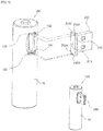
- FIG. 1 includes perspective views of a Universal Serial Bus (USB) terminal-equipped battery according to an embodiment of the present invention.
- USB Universal Serial Bus
- the USB terminal-equipped battery according to an embodiment of the present invention may be a cylindrical AA size battery but is not limited thereto.
- the USB terminal-equipped battery is applied to batteries having various sizes, such as CR123A, AAA, AA, C, D, FC-1, 4FM, etc.
- the USB terminal-equipped battery may be a Type A USB connector and port but is not limited thereto.
- the USB terminal-equipped battery is applied to various connectors and ports, such as Type A, Type B, Mini-A, Mini-B, Micro-A, Micro-B, etc.
- a USB terminal-equipped battery 100 includes a body part 10 and a variable cover 200.
- a positive (+) pole is formed on a top surface of the body part 10, and a negative (-) pole is formed on a bottom surface thereof.
- a condenser part 190, a controller part 150, and a memory part 170 are provided in the body part 10.
- a lead-acid battery, a nickel cadmium battery, a nickel-hydride battery, a lithium ion battery, a lithium polymer battery, or a fuel cell may be used as the condenser part 190 that is a secondary battery condenser part.
- the condenser part 190 is not limited to the secondary battery condenser part 190 but may be a primary battery condenser part.
- controller part 150 and the memory part 170 are the same as those of well-known technology and thus, a detailed description thereof will be omitted from the present specification.
- the body part 10 includes a USB female concave part 110 having a side into which a USB male part 300 is capable of being inserted.
- the USB female concave part 110 has a groove having the same size as that of the USB male part 300 into which the USB male part 300 is capable of being inserted.
- the USB female concave part 110 is configured to be electrically connected to the USB male part 300.
- the USB female concave part 110 has terminals formed on a ground surface into which the USB male part 300 is inserted, and the terminals 111, 112, 113, and 114 are electrically connected to the condenser part 190 and the controller part 150 provided in the body part.
- the USB female concave part 110 has terminals formed on a ground surface that contacts the USB male part 300, and the terminals include a concave part + terminal 112 and a concave part terminal 113 for charging and a concave part VCC terminal 111 and a concave part GND terminal 114 for data storing.
- the concave part VCC terminal 111 and the concave part GND terminal 114 are electrically connected to the memory part 170 through the controller part 150, and the concave part + terminal 112 and the concave part terminal 113 are electrically connected to the condenser part 190.
- terminals of the USB male part 300 are electrically connected to the condenser part 190 and the controller part 150 through the terminals 111, 112, 113, and 114 provided in the USB female concave part 110 so as to perform battery charging and data storing.
- a groove may be formed in one end of the USB female concave part 110 so that a cover body part 210 that will be described below may be inserted into the groove.
- a stepped concave part 130 formed to have a step height with the USB female concave part 110 may be provided in one end of the body part 10 of the USB female concave part 110 in a lateral direction so that the cover body part 210 may be inserted into the stepped concave part 130.
- a first face 211 and a second face 213 of the cover body part 210 protrude as an arc having the same size as that of a diameter of the body part 10, and the stepped concave part 130 is formed as a groove having the same shape as that of the first face 211 and the second face 213 so that the first face 211 or the second face 213 is inserted into the stepped concave part 130.
- a circumferential surface of the cover body part 210 is the same as a circumferential surface of the body part 10.
- a jaw does not protrude from an outer side of the cover body part 210 so that even when either one of the first face 211 and the second face 213 is inserted into the stepped concave part 130, the surface of the cover body part 210 and the surface of the stepped concave part 130 having the same shape may be maintained (see FIG. 1 ).
- a fingernail-shaped groove may be formed in one end of the body part 10 of the USB female concave part 110 in a direction of an outer side of the body part 10 so that the variable cover 200 that will be described below may be more easily dismantled from the body part 10.
- the USB terminal-equipped battery 100 includes one or more conductive protrusions 131, 132, 133, and 134 (or conductive protrusions 1300) formed on the stepped concave part 130, and the conductive protrusions 1300 are formed on a surface of the stepped concave part 130 and protrude outward from the body part 10.
- the conductive protrusions 131, 132, 133, and 134 include two data conductive protrusions 131 and 134 and two power conductive protrusions 132 and 133.
- Two pairs of conductive protrusions 1300 are formed in a positive pole direction of the body part 10 and a negative pole direction of the body part 10, respectively.
- the conductive protrusions 131 and 132 in the positive pole direction are spaced apart from each other, and the conductive protrusions 133 and 134 in the negative pole direction are adjacent to each other.
- a left side of the conductive protrusions 131 and 132 in the positive pole direction of the body part 10 is a VCC conductive protrusion 131
- a right side thereof is a positive (+) conductive protrusion 132
- a left side of the conductive protrusions 133 and 134 in the negative pole direction of the body part is a negative (-) conductive protrusion 133
- a right side thereof is a GND conductive protrusion 134.
- VCC conductive protrusion 131 and the GND conductive protrusion 134 are electrically connected to the memory part 170 through the controller part 150 in the body part 10, and the positive (+) conductive protrusion 132 and the negative (-) conductive protrusion 133 are electrically connected to the condenser part 190 in the body part 10.
- the conductive protrusions 1300 include the VCC conductive protrusion 131, the GND conductive protrusion 134, the positive (+) conductive protrusion 132, and the negative (-) conductive protrusion 133 and are connected to the condenser part 190 and the controller part 150 provided in the body part 10.
- the variable cover 200 includes the cover body part 210 and a USB male protrusion 230.
- the USB male protrusion 230 has the same shape as that of the USB female concave part 110, and terminals are provided on a ground surface that contacts a USB female part 410 so that the USB male protrusion 230 is inserted into a USB interface 400 having the same shape as that of the USB female part 410 and the terminals are connected to the USB female part 410.
- the USB male protrusion 230 is provided on the first face 211 of the cover body part 210, and the terminals of the USB male protrusion 230 include a USB positive (+) terminal 232 and a USB terminal 233 so that charging can be performed when the terminals of the USB male protrusion 230 are connected to the USB female part 410, and a USB VCC terminal 231 and a USB GND terminal 234 for data storing.
- one or more fixing openings 2110 are provided in the first face 211 of the cover body part 210.
- the one or more fixing openings 2110 are provided in corresponding positions in which, when the variable cover 200 is inserted into the USB female concave part 110 of the body part 10 in a direction of the first face 211, the conductive protrusions 1300 formed on the stepped concave part 13 can be inserted into the one or more fixing openings 2110.
- the fixing openings 2110 are provided in positions corresponding to the conductive protrusions 1300 and enable the variable cover 200 to be fixed to the body part 10 so as not to escape from the body part 10 when the variable cover 200 is inserted into the USB female concave part 110 of the body part 10 in the direction of the first face 211.
- the term "corresponding" refers to the same positions which are provided in the same direction and in which coupling can be performed.
- the fixing openings 2110 may be insulated so that no electricity flows through the fixing openings 2110.
- one or more conductive openings 2130 are provided on the second face 213 of the cover body part 210 so that the conductive protrusions 3100 may be inserted into the one or more conductive openings 2130.
- the one or more conductive openings 2130 are provided in corresponding positions so that, when the cover body part 210 is fastened to the body part 10 in the direction of the second face 213, the conductive protrusions 131, 132, 133, and 134 provided in the stepped concave part 130 can be inserted into the conductive openings 2130 provided in the cover body part 210.
- the one or more conductive openings 2130 include a VCC conductive opening 2131, a GND conductive opening 2134, a positive (+) conductive opening 2132, and a conductive opening 2133.
- the VCC conductive opening 2131 is provided in a position corresponding to the VCC conductive protrusion 131
- the GND conductive opening 2134 is provided in a position corresponding to the GND conductive protrusion 134
- the positive (+) conductive opening 2132 is provided in a position corresponding to the positive (+) conductive protrusion 132
- the conductive opening 2133 is provided in a position corresponding to the conductive protrusion 133.
- the term "corresponding" refers to the same positions which are provided in the same direction and in which coupling can be performed.
- the fixing openings 2110 provided in the first face 211 and the conductive openings 2130 provided in the second face 213 may be provided in reverse positions so that opened grooves of the fixing openings 2110 and the conductive openings 2130 do not overlap and thus do not interfere with one another.
- the conductive openings 2130 provided in the second face 213 are electrically connected to terminals 2300 provided in the USB male protrusion 230.
- the terminals include a USB VCC terminal 231, a USB GND terminal 234, a USB positive (+) terminal 232, and a USB terminal 233.
- the USB VCC terminal 231 is electrically connected to the VCC conductive opening 2131
- the USB GND terminal 234 is electrically connected to the GND conductive opening 2134
- the USB positive (+) terminal 232 is electrically connected to the positive (+) conductive opening 2132
- the USB terminal 233 is electrically connected to the conductive opening 2133.
- variable cover 200 when the variable cover 200 is inserted into the body part 10 in the direction of the first face 211, the variable cover 200 is used to prevent foreign matter from being introduced into the USB female concave part 110 (see FIG. 1 ).
- variable cover 200 When the variable cover 200 is removed from the body part 10, battery charging and data storing can be performed using the USB interface 400 to which the USB male part 300 is applied (see FIG. 2 ).
- variable cover 200 when the variable cover 200 is inserted into the body part 10 in the direction of the second face 213, battery charging and data storing can be performed using the USB interface 400 to which the USB female part 410 is applied, so that a user can use the variable cover 200 regardless of the shape of terminals of the USB interface 400 (see FIG. 5 ).
- a USB terminal-equipped battery according to another embodiment of the present invention applied to an FC-1 type battery having a voltage of 9V may be an AA type battery and an FC-1 type battery, but is not limited thereto and may be applied to batteries having various types of shapes and voltages.
- USB terminal-equipped battery 10 body part 110: USB female concave part 111: concave part VCC terminal 112: concave part positive (+) terminal 113: concave part terminal 114: concave part GND terminal 130: stepped concave part 1300: conductive protrusion 131: VCC conductive protrusion 132: positive (+) conductive protrusion 133: negative (-) conductive protrusion 134: GND conductive protrusion 150: controller part 170: memory part 190: condenser part 200: variable cover 210: cover body part 211: first face 2110: fixing opening 213: second face 230: USB male protrusion 2130: conductive opening 2131: VCC conductive opening 2132: positive (+)
- a Universal Serial Bus (USB) terminal-equipped battery includes a USB female concave part at a side of a body part so that a battery can be charged using a USB interface including a USB male part, and further includes a variable cover so that foreign matter can be prevented from being introduced into the USB female concave part. Also, a stepped concave part is provided so that, when the variable cover is inserted, the variable cover can be stably fixed to the body part due to the stepped concave part.
- a battery that is portable is provided with USB terminals and is capable of being selectively connected to a USB female part or a USB male part through the variable cover, can be provided.
Landscapes
- Chemical & Material Sciences (AREA)
- Chemical Kinetics & Catalysis (AREA)
- Electrochemistry (AREA)
- General Chemical & Material Sciences (AREA)
- Engineering & Computer Science (AREA)
- Power Engineering (AREA)
- Manufacturing & Machinery (AREA)
- Charge And Discharge Circuits For Batteries Or The Like (AREA)
- Battery Mounting, Suspending (AREA)
Abstract
Description
- The present invention relates to a Universal Serial Bus (USB) terminal-equipped battery, and more particularly, to a USB terminal-equipped battery including a USB female concave part such that the battery can be charged through a USB interface, and further including an additional variable cover such that a user can conveniently charge the battery even in different USB interface environments.
- A battery is a portable energy source indispensable in everyday life, and the problem of waste batteries in Korea has been discussed in the document published by the Ministry of Environment on September 22, 2009 disclosing that 600 million or more primary batteries per year are used and disposed, and only approximately 6% batteries are recycled. A charging battery (a secondary battery) that enables a waste battery to be recycled is used as a means for solving the problem. In detail, a charging method, wherein an adapter is connected to a household outlet and a USB interface so that an exclusive charging battery can be inserted, is used in the conventional battery.
- However, in the conventional battery, an exclusive charging adapter including a booster circuit has to be additionally provided in addition to a battery, and a charging method using a USB interface requires a configuration of only a USB male part or USB female part, and when a position of the USB interface is a position that a user cannot easily approach, there is a difficulty in using a USB cable. Also, the user separately has to provide a USB adapter suitable for the user so as to perform charging.
- Prior Art Documents 1, 2, 3, and 4 disclose a mobile phone charging device using a battery and having a function of inserting the battery into a housing and charging an electronic device using a booster circuit.
- Nevertheless, since the device for charging an electronic device using a battery disclosed in Prior Art Documents 1, 2, 3, and 4 includes the booster circuit, the battery can be charged. However, a charging operation has to be performed using an additional housing and an additional adapter separately.
-
- (Patent Document 1) Prior Art Document 1: Korean Patent Laid-open Publication No.
10-2006-0050085 - (Patent Document 2) Prior Art Document 2: Korean Utility-model Registration No.
20-0431515 - (Patent Document 3) Prior Art Document 3: Korean Utility-model Registration No.
20-0335683 - (Patent Document 4) Prior Art Document 4: Korean Patent Laid-open Publication No.
10-2006-0050084 - The present invention is directed to providing a Universal Serial Bus (USB) terminal-equipped battery which can be connected to a USB interface so that the battery can be charged.
- Furthermore, the present invention is also directed to providing a charging method, whereby both a USB male part and a USB female part can be used so as to enhance versatility.
- Furthermore, the present invention is also directed to providing a variable cover that prevents foreign matter, such as dust, from penetrating into an opening of a USB female concave part.
- One aspect of the present invention provides a Universal Serial Bus (USB) terminal-equipped battery including a body part and a variable cover, wherein the body part includes a USB female concave part, which is disposed at a side of the body part and into which a USB male part is inserted, and the variable cover includes a USB male protrusion and a cover body part, and a stepped concave part is formed at one end of the USB female concave part so as to accommodate the cover body part. In detail, the stepped concave part may include conductive protrusions through which the stepped concave part is electrically connected to the variable cover.
- According to the present invention, since the USB terminal-equipped battery includes a USB female concave part disposed at a side of a body part, a battery can be charged using a USB interface including a USB male part.
- Since the USB terminal-equipped battery further includes a variable cover, foreign substances can be prevented from being introduced into the USB female concave part.
- Also, since the USB terminal-equipped battery provides a stepped concave part, when the variable cover is inserted into the stepped concave part, the variable cover can be fixed to the body part due to the stepped concave part.
- Meanwhile, since the variable cover includes a USB male protrusion, the battery can be charged using a USB interface including a USB female part.
- Meanwhile, a controller part and a memory part are provided in the battery so that data storing can be performed using the USB interface.
- That is, as described above, since a USB interface including a USB male part and a USB female part can be used, a USB terminal-equipped battery in which a user can perform battery charging and data storing without an additional adapter, can be provided.
-
-
FIG. 1 includes perspective views of a Universal Serial Bus (USB) terminal-equipped battery according to an embodiment of the present invention. -
FIG 2 includes perspective views of the USB terminal-equipped battery according to an embodiment of the present invention, and the use of a USB interface using a USB male part. -
FIG. 3 includes a view of the USB terminal-equipped battery according to an embodiment of the present invention and a cross-sectional view illustrating the use of a USB interface using a USB male part. -
FIG. 4 includes a view of the USB terminal-equipped battery according to an embodiment of the present invention and a perspective view when a variable cover is inserted into a body part in a direction of a first face. -
FIG. 5 includes a view of the USB terminal-equipped battery according to an embodiment of the present invention and a perspective view when a variable cover is inserted into a body part in a direction of a second face. -
FIG. 6 includes a view of the USB terminal-equipped battery according to an embodiment of the present invention and a cross-sectional view when a variable cover is inserted. -
FIG. 7 is a perspective view of a variable cover of the USB terminal-equipped battery according to an embodiment of the present invention. -
FIG. 8 is a cross-sectional view of the variable cover of the USB terminal-equipped battery according to an embodiment of the present invention. -
FIG 9 is a perspective view of an exemplary embodiment in which the USB terminal-equipped battery according to an embodiment of the present invention is charged through a USB interface. -
FIG. 10 is a perspective view of another embodiment in which a body part of the USB terminal-equipped battery according to an embodiment of the present invention is applied to a rectangular battery. - Hereinafter, exemplary embodiments of the present invention will be described in detail with reference to the attached drawings. In this procedure, sizes or shapes of elements shown in the drawings may be exaggerated for clarity and convenience of explanation. Also, terms that are particularly defined in consideration of the configuration and operation of the present invention may be changed according to a user or operator's intention or practice. Therefore, definitions of the terms should be made based on the contents of the present specification. The spirit of the present invention is not limited to the suggested embodiments, and those skilled in the art who understand the spirit of the present invention can easily embody another embodiment within the scope of the same spirit and this also belongs to the scope of the present invention.
-
FIG. 1 includes perspective views of a Universal Serial Bus (USB) terminal-equipped battery according to an embodiment of the present invention. Hereinafter, a description will be based onFIG. 1 , and a configuration that is not shown inFIG. 1 is separately indicated in reference drawings. - The USB terminal-equipped battery according to an embodiment of the present invention may be a cylindrical AA size battery but is not limited thereto. The USB terminal-equipped battery is applied to batteries having various sizes, such as CR123A, AAA, AA, C, D, FC-1, 4FM, etc.
- The USB terminal-equipped battery according to an embodiment of the present invention may be a Type A USB connector and port but is not limited thereto. The USB terminal-equipped battery is applied to various connectors and ports, such as Type A, Type B, Mini-A, Mini-B, Micro-A, Micro-B, etc.
- A USB terminal-equipped
battery 100 according to an embodiment of the present invention includes abody part 10 and avariable cover 200. - A positive (+) pole is formed on a top surface of the
body part 10, and a negative (-) pole is formed on a bottom surface thereof. As illustrated inFIG. 3 , acondenser part 190, acontroller part 150, and amemory part 170 are provided in thebody part 10. - A lead-acid battery, a nickel cadmium battery, a nickel-hydride battery, a lithium ion battery, a lithium polymer battery, or a fuel cell may be used as the
condenser part 190 that is a secondary battery condenser part. Thecondenser part 190 is not limited to the secondarybattery condenser part 190 but may be a primary battery condenser part. - The configuration and connection relationship of the
controller part 150 and thememory part 170 are the same as those of well-known technology and thus, a detailed description thereof will be omitted from the present specification. - Referring to
FIGS. 1 and 2 , thebody part 10 includes a USB femaleconcave part 110 having a side into which a USBmale part 300 is capable of being inserted. In detail, the USB femaleconcave part 110 has a groove having the same size as that of the USBmale part 300 into which the USBmale part 300 is capable of being inserted. The USB femaleconcave part 110 is configured to be electrically connected to the USBmale part 300. Additionally, referring toFIGS. 4 ,5 , and7 , the USB femaleconcave part 110 has terminals formed on a ground surface into which the USBmale part 300 is inserted, and theterminals condenser part 190 and thecontroller part 150 provided in the body part. In detail, the USB femaleconcave part 110 has terminals formed on a ground surface that contacts the USBmale part 300, and the terminals include a concave part +terminal 112 and aconcave part terminal 113 for charging and a concavepart VCC terminal 111 and a concavepart GND terminal 114 for data storing. As illustrated inFIG. 3 , the concavepart VCC terminal 111 and the concavepart GND terminal 114 are electrically connected to thememory part 170 through thecontroller part 150, and the concave part +terminal 112 and theconcave part terminal 113 are electrically connected to thecondenser part 190. - That is, when the USB
male part 300 is inserted into the USB femaleconcave part 110, terminals of the USBmale part 300 are electrically connected to thecondenser part 190 and thecontroller part 150 through theterminals concave part 110 so as to perform battery charging and data storing. - Referring to
FIGS. 1 ,4 , and5 , a groove may be formed in one end of the USB femaleconcave part 110 so that acover body part 210 that will be described below may be inserted into the groove. In detail, a steppedconcave part 130 formed to have a step height with the USB femaleconcave part 110 may be provided in one end of thebody part 10 of the USB femaleconcave part 110 in a lateral direction so that thecover body part 210 may be inserted into the steppedconcave part 130. In more detail, afirst face 211 and asecond face 213 of thecover body part 210 that will be described below protrude as an arc having the same size as that of a diameter of thebody part 10, and the steppedconcave part 130 is formed as a groove having the same shape as that of thefirst face 211 and thesecond face 213 so that thefirst face 211 or thesecond face 213 is inserted into the steppedconcave part 130. - That is, when the
cover body part 210 is inserted into the steppedconcave part 130 provided in the USB femaleconcave part 110, a circumferential surface of thecover body part 210 is the same as a circumferential surface of thebody part 10. Thus, when thecover body part 210 is inserted into the steppedconcave part 130, a jaw does not protrude from an outer side of thecover body part 210 so that even when either one of thefirst face 211 and thesecond face 213 is inserted into the steppedconcave part 130, the surface of thecover body part 210 and the surface of the steppedconcave part 130 having the same shape may be maintained (seeFIG. 1 ). - Also, a fingernail-shaped groove may be formed in one end of the
body part 10 of the USB femaleconcave part 110 in a direction of an outer side of thebody part 10 so that thevariable cover 200 that will be described below may be more easily dismantled from thebody part 10. - Referring to
FIGS. 4 and5 , the USB terminal-equippedbattery 100 according to an embodiment of the present invention includes one or moreconductive protrusions concave part 130, and the conductive protrusions 1300 are formed on a surface of the steppedconcave part 130 and protrude outward from thebody part 10. In detail, theconductive protrusions conductive protrusions conductive protrusions body part 10 and a negative pole direction of thebody part 10, respectively. In more detail, theconductive protrusions conductive protrusions conductive protrusions body part 10 is a VCCconductive protrusion 131, a right side thereof is a positive (+)conductive protrusion 132, a left side of theconductive protrusions conductive protrusion 133, and a right side thereof is a GNDconductive protrusion 134. The VCCconductive protrusion 131 and the GNDconductive protrusion 134 are electrically connected to thememory part 170 through thecontroller part 150 in thebody part 10, and the positive (+)conductive protrusion 132 and the negative (-)conductive protrusion 133 are electrically connected to thecondenser part 190 in thebody part 10. - That is, referring to
FIGS. 3 and6 , the conductive protrusions 1300 include the VCCconductive protrusion 131, the GNDconductive protrusion 134, the positive (+)conductive protrusion 132, and the negative (-)conductive protrusion 133 and are connected to thecondenser part 190 and thecontroller part 150 provided in thebody part 10. - Referring to
FIGS. 7 and8 , in an embodiment of the present invention, thevariable cover 200 includes thecover body part 210 and aUSB male protrusion 230. In detail, theUSB male protrusion 230 has the same shape as that of the USB femaleconcave part 110, and terminals are provided on a ground surface that contacts a USBfemale part 410 so that theUSB male protrusion 230 is inserted into aUSB interface 400 having the same shape as that of the USBfemale part 410 and the terminals are connected to the USBfemale part 410. In detail, theUSB male protrusion 230 is provided on thefirst face 211 of thecover body part 210, and the terminals of theUSB male protrusion 230 include a USB positive (+) terminal 232 and aUSB terminal 233 so that charging can be performed when the terminals of theUSB male protrusion 230 are connected to the USBfemale part 410, and aUSB VCC terminal 231 and aUSB GND terminal 234 for data storing. Referring toFIG. 4 , one or more fixing openings 2110 are provided in thefirst face 211 of thecover body part 210. In detail, the one or more fixing openings 2110 are provided in corresponding positions in which, when thevariable cover 200 is inserted into the USB femaleconcave part 110 of thebody part 10 in a direction of thefirst face 211, the conductive protrusions 1300 formed on the stepped concave part 13 can be inserted into the one or more fixing openings 2110. In more detail, the fixing openings 2110 are provided in positions corresponding to the conductive protrusions 1300 and enable thevariable cover 200 to be fixed to thebody part 10 so as not to escape from thebody part 10 when thevariable cover 200 is inserted into the USB femaleconcave part 110 of thebody part 10 in the direction of thefirst face 211. The term "corresponding" refers to the same positions which are provided in the same direction and in which coupling can be performed. Additionally, the fixing openings 2110 may be insulated so that no electricity flows through the fixing openings 2110. - Referring to
FIGS. 5 and6 , one or more conductive openings 2130 are provided on thesecond face 213 of thecover body part 210 so that the conductive protrusions 3100 may be inserted into the one or more conductive openings 2130. In detail, the one or more conductive openings 2130 are provided in corresponding positions so that, when thecover body part 210 is fastened to thebody part 10 in the direction of thesecond face 213, theconductive protrusions concave part 130 can be inserted into the conductive openings 2130 provided in thecover body part 210. In more detail, the one or more conductive openings 2130 include a VCCconductive opening 2131, a GNDconductive opening 2134, a positive (+)conductive opening 2132, and aconductive opening 2133. In further detail, the VCCconductive opening 2131 is provided in a position corresponding to the VCCconductive protrusion 131, the GNDconductive opening 2134 is provided in a position corresponding to the GNDconductive protrusion 134, the positive (+)conductive opening 2132 is provided in a position corresponding to the positive (+)conductive protrusion 132, and theconductive opening 2133 is provided in a position corresponding to theconductive protrusion 133. The term "corresponding" refers to the same positions which are provided in the same direction and in which coupling can be performed. - Referring to
FIG. 7 , the fixing openings 2110 provided in thefirst face 211 and the conductive openings 2130 provided in thesecond face 213 may be provided in reverse positions so that opened grooves of the fixing openings 2110 and the conductive openings 2130 do not overlap and thus do not interfere with one another. - Referring to
FIGS. 5 and6 , the conductive openings 2130 provided in thesecond face 213 are electrically connected to terminals 2300 provided in theUSB male protrusion 230. In detail, the terminals include aUSB VCC terminal 231, aUSB GND terminal 234, a USB positive (+) terminal 232, and aUSB terminal 233. In more detail, theUSB VCC terminal 231 is electrically connected to the VCCconductive opening 2131, theUSB GND terminal 234 is electrically connected to the GNDconductive opening 2134, the USB positive (+) terminal 232 is electrically connected to the positive (+)conductive opening 2132, and theUSB terminal 233 is electrically connected to theconductive opening 2133. - That is, when the
variable cover 200 is inserted into thebody part 10 in the direction of thefirst face 211, thevariable cover 200 is used to prevent foreign matter from being introduced into the USB female concave part 110 (seeFIG. 1 ). - When the
variable cover 200 is removed from thebody part 10, battery charging and data storing can be performed using theUSB interface 400 to which the USBmale part 300 is applied (seeFIG. 2 ). - Also, when the
variable cover 200 is inserted into thebody part 10 in the direction of thesecond face 213, battery charging and data storing can be performed using theUSB interface 400 to which the USBfemale part 410 is applied, so that a user can use thevariable cover 200 regardless of the shape of terminals of the USB interface 400 (seeFIG. 5 ). - Referring to
FIG. 10 , a USB terminal-equipped battery according to another embodiment of the present invention applied to an FC-1 type battery having a voltage of 9V may be an AA type battery and an FC-1 type battery, but is not limited thereto and may be applied to batteries having various types of shapes and voltages. - While the invention has been shown and described with reference to certain exemplary embodiments thereof, it will be understood by those skilled in the art that various changes in form and details may be made therein without departing from the spirit and scope of the invention as defined by the appended claims.
Explanation of reference numerals 100: USB terminal-equipped battery 10: body part 110: USB female concave part 111: concave part VCC terminal 112: concave part positive (+) terminal 113: concave part terminal 114: concave part GND terminal 130: stepped concave part 1300: conductive protrusion 131: VCC conductive protrusion 132: positive (+) conductive protrusion 133: negative (-) conductive protrusion 134: GND conductive protrusion 150: controller part 170: memory part 190: condenser part 200: variable cover 210: cover body part 211: first face 2110: fixing opening 213: second face 230: USB male protrusion 2130: conductive opening 2131: VCC conductive opening 2132: positive (+) conductive opening 2133: negative (-) conductive opening 2134: GND conductive opening 2300: USB male protrusion terminal 231: USB VCC terminal 232: USB positive (+) terminal 233: USB terminal 234: USB GND terminal 300: USB male part 400: USB interface 410: USB female part - According to the present invention, since a Universal Serial Bus (USB) terminal-equipped battery includes a USB female concave part at a side of a body part so that a battery can be charged using a USB interface including a USB male part, and further includes a variable cover so that foreign matter can be prevented from being introduced into the USB female concave part. Also, a stepped concave part is provided so that, when the variable cover is inserted, the variable cover can be stably fixed to the body part due to the stepped concave part.
- Thus, according to the present invention, a battery that is portable, is provided with USB terminals and is capable of being selectively connected to a USB female part or a USB male part through the variable cover, can be provided.
Claims (10)
- A Universal Serial Bus (USB)-terminal equipped battery (100) charged through a USB interface, comprising:a USB female concave part (110) into which a USB male part is inserted; anda stepped concave part (130) formed at one end of the USB female concave part (110) to have a step height with the USB female concave part (110).
- The USB-terminal equipped battery of claim 1, wherein the stepped concave part (130) includes one or more conductive protrusions (1300) formed at one end of the stepped concave part (130) and protruding outward.
- The USB-terminal equipped battery of claim 2, further comprising a variable cover (200),
wherein the variable cover (200) comprises:a cover body part (210) inserted into the stepped concave part (130); anda USB male protrusion (230) inserted into the USB female concave part (110) and formed at a first face (211) of the cover body part (210). - The USB-terminal equipped battery of claim 3, wherein one or more fixing openings (2110) into which the one or more conductive protrusions (1300) are inserted, are provided in the first face (211) of the cover body part (210).
- The USB-terminal equipped battery of claim 4, wherein the one or more fixing openings (2110) are insulated.
- The USB-terminal equipped battery of claim 3, wherein one or more conductive openings (2130) into which the one or more conductive protrusions (1300) are inserted, are provided in a second face (213) of the cover body part (210).
- The USB-terminal equipped battery of claim 6, wherein the conductive openings (2130) provided in the second face (213) of the cover body part (210) are electrically connected to terminals (2300) of the USB male protrusion (230) of the variable cover (200).
- The USB-terminal equipped battery of claim 6, wherein the conductive openings (2130) provided in the second face (213) of the cover body part (210) are electrically connected to terminals (2300) of the USB male protrusion (230) of the variable cover (200).
- The USB-terminal equipped battery of claim 2, wherein one end of the one or more conductive protrusions (1300) is electrically connected to a memory part (150) provided in the battery through a controller part.
- The USB-terminal equipped battery of claim 2, wherein power is supplied to a condenser part (190) provided in the battery through one end of the one or more conductive protrusions (1300).
Applications Claiming Priority (2)
| Application Number | Priority Date | Filing Date | Title |
|---|---|---|---|
| KR20140075985A KR101472537B1 (en) | 2014-06-20 | 2014-06-20 | Rechargeable battery with Universal Serial Bus connecter |
| PCT/KR2014/011245 WO2015194714A1 (en) | 2014-06-20 | 2014-11-21 | Usb terminal-equipped battery |
Publications (2)
| Publication Number | Publication Date |
|---|---|
| EP3171428A1 true EP3171428A1 (en) | 2017-05-24 |
| EP3171428A4 EP3171428A4 (en) | 2017-11-01 |
Family
ID=52678821
Family Applications (1)
| Application Number | Title | Priority Date | Filing Date |
|---|---|---|---|
| EP14894941.5A Withdrawn EP3171428A4 (en) | 2014-06-20 | 2014-11-21 | Usb terminal-equipped battery |
Country Status (6)
| Country | Link |
|---|---|
| US (1) | US20160260955A1 (en) |
| EP (1) | EP3171428A4 (en) |
| JP (1) | JP2017519348A (en) |
| KR (1) | KR101472537B1 (en) |
| CN (1) | CN205790169U (en) |
| WO (1) | WO2015194714A1 (en) |
Families Citing this family (25)
| Publication number | Priority date | Publication date | Assignee | Title |
|---|---|---|---|---|
| USD822591S1 (en) * | 2015-09-14 | 2018-07-10 | Wenzhou Shengbo Technology Co., Ltd. | Rechargeable battery with universal serial bus (USB) connector |
| KR20180004388A (en) * | 2016-07-03 | 2018-01-11 | 삼성전자주식회사 | Terminal, input apparatus and power controlling method thereof |
| USD899355S1 (en) * | 2016-08-15 | 2020-10-20 | Milwaukee Electric Tool Corporation | Battery |
| US11271269B2 (en) | 2016-10-14 | 2022-03-08 | Milwaukee Electric Tool Corporation | Battery pack |
| KR101805886B1 (en) | 2016-12-05 | 2018-01-11 | (주) 제이앤케이사이언스 | Rechargeable battery with universal serial bus connecter |
| KR20180064961A (en) | 2017-06-08 | 2018-06-15 | (주) 제이앤케이사이언스 | A usb terminal-equipped battery having ring shape connection element |
| USD844557S1 (en) * | 2017-12-13 | 2019-04-02 | Shen Zhen Oriental Vision Battery Co., Ltd | Lighting battery |
| USD889401S1 (en) * | 2018-10-24 | 2020-07-07 | Shenzhen Lepower Electronic Co., Ltd. | USB portable power supply |
| USD911926S1 (en) * | 2019-03-13 | 2021-03-02 | Ningbo Roca Superior Products E-Commerce Co., Ltd | Rechargeable battery |
| USD929315S1 (en) * | 2019-03-15 | 2021-08-31 | The Coleman Company, Inc. | Interchangeable battery |
| CN110233283B (en) * | 2019-07-10 | 2021-07-23 | 深圳先进储能材料国家工程研究中心有限公司 | High energy density secondary lithium ion battery |
| USD926120S1 (en) * | 2019-08-14 | 2021-07-27 | Birota | Rechargeable battery |
| USD942967S1 (en) * | 2019-12-09 | 2022-02-08 | Shenzhen Xiaoshi Technology Co., Ltd. | Rechargeable controller for string lights |
| CN111063856B (en) * | 2019-12-17 | 2022-06-10 | 深圳先进储能材料国家工程研究中心有限公司 | Secondary batteries based on needle-shaped lead cells |
| EP4085435A4 (en) * | 2020-01-03 | 2024-01-17 | Skybell Technologies, Inc. | DOORBELL COMMUNICATION SYSTEMS AND METHODS |
| KR102269644B1 (en) * | 2020-05-08 | 2021-06-25 | 주식회사 바스맨테크놀러지 | Battery of USB Charge Type |
| USD1066239S1 (en) * | 2023-01-07 | 2025-03-11 | Shenzhen Lepower Electronic Co., Ltd. | Lithium battery |
| USD1067177S1 (en) * | 2023-01-07 | 2025-03-18 | Shenzhen Lepower Electronic Co., Ltd. | Lithium battery |
| USD1055845S1 (en) * | 2023-05-11 | 2024-12-31 | Shenzhen Your Power Technology Co., LTD | Rechargeable battery |
| USD1041668S1 (en) * | 2023-07-28 | 2024-09-10 | Bei Zou | Hand warmer |
| USD1057971S1 (en) * | 2023-08-02 | 2025-01-14 | Bei Zou | Hand warmer |
| USD1075643S1 (en) * | 2023-10-31 | 2025-05-20 | Dongguan Beston Digital Technology Co., LTD | Battery |
| USD1119759S1 (en) * | 2024-09-06 | 2026-03-24 | Ningbo Takenow Technology Co., Ltd. | Battery |
| USD1054974S1 (en) * | 2024-09-10 | 2024-12-24 | Xingyan Feng | Battery |
| USD1106954S1 (en) * | 2024-10-28 | 2025-12-23 | Shenzhen Oriental Willing New Energy Co., Ltd | Rechargeable battery |
Family Cites Families (12)
| Publication number | Priority date | Publication date | Assignee | Title |
|---|---|---|---|---|
| JP4446390B2 (en) | 2006-01-18 | 2010-04-07 | パナソニック株式会社 | Charger |
| TWM297579U (en) * | 2006-01-30 | 2006-09-11 | Samya Technology Co Ltd | Portable mobile power supply |
| US8058840B2 (en) * | 2006-05-25 | 2011-11-15 | Moxia Energy Holdings Limited | Rechargeable battery assembly with movable connector and power conversion circuitry |
| KR20070001327U (en) * | 2007-12-05 | 2007-12-31 | 김대규 | Battery with USB terminal and charging circuit |
| KR101290321B1 (en) * | 2011-03-11 | 2013-07-26 | (주)우영에너지홀딩스 | Battery have USB Port and Charge Circuit |
| US20130043827A1 (en) * | 2011-08-10 | 2013-02-21 | Nathan Daniel Weinstein | Portable power charger |
| US9312706B2 (en) * | 2012-01-06 | 2016-04-12 | Goal Zero Llc | Reconfigurable energy storage and power supply device |
| JPWO2013161092A1 (en) * | 2012-04-27 | 2015-12-21 | トリニティ株式会社 | Portable battery |
| JP5976480B2 (en) * | 2012-09-25 | 2016-08-23 | 三洋電機株式会社 | Portable power supply |
| US9385549B2 (en) * | 2013-03-20 | 2016-07-05 | Halo2Cloud, LLC. | Portable power charger with power input and power output connection interfaces |
| KR20130103471A (en) * | 2013-08-26 | 2013-09-23 | 주식회사 엘지화학 | Charging battery having universal serial bus port |
| US9923393B2 (en) * | 2014-07-09 | 2018-03-20 | Goal Zero Llc | Energy storage and power supply system |
-
2014
- 2014-06-20 KR KR20140075985A patent/KR101472537B1/en active Active
- 2014-11-21 EP EP14894941.5A patent/EP3171428A4/en not_active Withdrawn
- 2014-11-21 WO PCT/KR2014/011245 patent/WO2015194714A1/en not_active Ceased
- 2014-11-21 CN CN201490001055.8U patent/CN205790169U/en not_active Expired - Fee Related
- 2014-11-21 JP JP2017519428A patent/JP2017519348A/en active Pending
- 2014-11-21 US US14/894,430 patent/US20160260955A1/en not_active Abandoned
Also Published As
| Publication number | Publication date |
|---|---|
| US20160260955A1 (en) | 2016-09-08 |
| EP3171428A4 (en) | 2017-11-01 |
| JP2017519348A (en) | 2017-07-13 |
| WO2015194714A1 (en) | 2015-12-23 |
| CN205790169U (en) | 2016-12-07 |
| KR101472537B1 (en) | 2014-12-16 |
Similar Documents
| Publication | Publication Date | Title |
|---|---|---|
| EP3171428A1 (en) | Usb terminal-equipped battery | |
| RU2464690C2 (en) | Charging device for accumulator battery and combination of accumulator batteries and charging device | |
| RU2283521C2 (en) | Multipurpose shaped plug and plug connectors for power supplies | |
| EP1753050A3 (en) | Secondary battery | |
| CN104578231A (en) | Chargers and Charging Systems | |
| US20180083464A1 (en) | Charging case for an electronic device | |
| JP3133242U (en) | Ear Hearing Aid Charger | |
| TWM311179U (en) | Mini dual-purpose charger | |
| US20180090964A1 (en) | Apparatus for powering an electrical device from different battery packs | |
| EP2506341A2 (en) | Improved interchangeable rechargeable battery system | |
| US10432000B2 (en) | Portable charger having switch for adjusting voltage thereof | |
| US6323621B1 (en) | Battery lead with charging and operating connection | |
| KR101505664B1 (en) | Rechargeable battery with universal serial bus connecter | |
| CN205304273U (en) | Mobile power supply | |
| US20120098478A1 (en) | Charger for an electronic device | |
| KR101397859B1 (en) | Assembly structure of battery for portable terminal | |
| CN105577865B (en) | The electronic equipment protection shell and matched plug connector of more charging/data-interfaces | |
| KR101777333B1 (en) | Plug Connector, And Battery Pack And Energy Storage System Comprising The Same | |
| CN101901973B (en) | Improved charging interface for rechargeable devices | |
| KR101220142B1 (en) | Point contact type apparatus for charging mobile terminal | |
| CN221900067U (en) | A convenient rechargeable battery | |
| CN102468661B (en) | Charger | |
| KR200279618Y1 (en) | A recharging connector of mobile phone | |
| US20130072069A1 (en) | Charger | |
| KR101805886B1 (en) | Rechargeable battery with universal serial bus connecter |
Legal Events
| Date | Code | Title | Description |
|---|---|---|---|
| PUAI | Public reference made under article 153(3) epc to a published international application that has entered the european phase |
Free format text: ORIGINAL CODE: 0009012 |
|
| 17P | Request for examination filed |
Effective date: 20161028 |
|
| AK | Designated contracting states |
Kind code of ref document: A1 Designated state(s): AL AT BE BG CH CY CZ DE DK EE ES FI FR GB GR HR HU IE IS IT LI LT LU LV MC MK MT NL NO PL PT RO RS SE SI SK SM TR |
|
| AX | Request for extension of the european patent |
Extension state: BA ME |
|
| DAX | Request for extension of the european patent (deleted) | ||
| A4 | Supplementary search report drawn up and despatched |
Effective date: 20171004 |
|
| RIC1 | Information provided on ipc code assigned before grant |
Ipc: H01M 2/30 20060101AFI20170927BHEP Ipc: H01M 10/46 20060101ALI20170927BHEP Ipc: H01M 2/02 20060101ALI20170927BHEP Ipc: H02J 7/00 20060101ALI20170927BHEP |
|
| STAA | Information on the status of an ep patent application or granted ep patent |
Free format text: STATUS: THE APPLICATION IS DEEMED TO BE WITHDRAWN |
|
| 18D | Application deemed to be withdrawn |
Effective date: 20180501 |