EP3171416A1 - Electrode laminate structure energy conversion apparatus using liquid - Google Patents
Electrode laminate structure energy conversion apparatus using liquid Download PDFInfo
- Publication number
- EP3171416A1 EP3171416A1 EP15821895.8A EP15821895A EP3171416A1 EP 3171416 A1 EP3171416 A1 EP 3171416A1 EP 15821895 A EP15821895 A EP 15821895A EP 3171416 A1 EP3171416 A1 EP 3171416A1
- Authority
- EP
- European Patent Office
- Prior art keywords
- electrode
- energy conversion
- liquid
- conversion device
- substrate
- Prior art date
- Legal status (The legal status is an assumption and is not a legal conclusion. Google has not performed a legal analysis and makes no representation as to the accuracy of the status listed.)
- Granted
Links
Images


Classifications
-
- H—ELECTRICITY
- H02—GENERATION; CONVERSION OR DISTRIBUTION OF ELECTRIC POWER
- H02N—ELECTRIC MACHINES NOT OTHERWISE PROVIDED FOR
- H02N1/00—Electrostatic generators or motors using a solid moving electrostatic charge carrier
- H02N1/06—Influence generators
- H02N1/08—Influence generators with conductive charge carrier, i.e. capacitor machines
-
- H—ELECTRICITY
- H02—GENERATION; CONVERSION OR DISTRIBUTION OF ELECTRIC POWER
- H02N—ELECTRIC MACHINES NOT OTHERWISE PROVIDED FOR
- H02N2/00—Electric machines in general using piezoelectric effect, electrostriction or magnetostriction
- H02N2/18—Electric machines in general using piezoelectric effect, electrostriction or magnetostriction producing electrical output from mechanical input, e.g. generators
- H02N2/185—Electric machines in general using piezoelectric effect, electrostriction or magnetostriction producing electrical output from mechanical input, e.g. generators using fluid streams
-
- H—ELECTRICITY
- H02—GENERATION; CONVERSION OR DISTRIBUTION OF ELECTRIC POWER
- H02N—ELECTRIC MACHINES NOT OTHERWISE PROVIDED FOR
- H02N2/00—Electric machines in general using piezoelectric effect, electrostriction or magnetostriction
- H02N2/18—Electric machines in general using piezoelectric effect, electrostriction or magnetostriction producing electrical output from mechanical input, e.g. generators
Definitions
- the present invention relates to an energy conversion device using liquid, more particularly, to an energy conversion device converting the mechanical energy generated by the flow of a liquid into an electrical energy.
- the energy conversion technologies of the prior art for converting mechanical energy into electrical energy use a principle that electrical capacitance is being created in the electrode under a dielectric material by varying the contact surface of a liquid metal which is in contact with a dielectric material in accordance with the flow of time.
- an electrode having a predetermined pattern is formed on the wall having the shape of a thin and long channel, and a dielectric material layer is formed above the electrode. Then, a small waterdrop-like conductive liquid and a non-conductive liquid are being injected into the channel, and the conductive liquid is depolarized by applying a voltage from an external power source to such waterdrop-like conductive liquid.
- the two facing electrodes must be patterned in a predetermined shape on the channel wall making the device configuration complicated due to such a structure, and the size of the module generating electrical energy becomes large, and there has been many limitations in mass production or cost reduction.
- the method and the device of the prior art for converting energy using a fluid have problems in that the reversible movements in the channel structure must be continuously implemented, and the control is difficult since two different kinds of immiscible liquids must be used.
- An objective of the present invention is to provide a method and a device for converting energy using a liquid, especially for generating electrical energy by changing the contact surface between the liquid and the electrodes in the device.
- Another objective of the present invention is to provide an efficient method and a device for converting energy while having a simple structure and a lower failure rate through implementation of a structure wherein electrodes are being stacked using an energy conversion layer.
- an electrode stacked energy conversion device using a liquid comprises: a substrate; a first electrode formed in the substrate; a first energy conversion layer formed in the first electrode and covering the first electrode; and a second electrode formed on the first energy conversion layer, wherein the contact state of the second electrode with respect to the liquid is being changed according to the movement or the state of the liquid.
- the electrode stacked energy conversion device using a liquid may further comprise a second energy conversion layer formed on the second electrode and covering the second electrode.
- the first electrode includes a plurality of first electrodes formed on the substrate and spaced apart from each other with a predetermined distance along a certain direction.
- the second electrode includes a plurality of second electrodes formed on the energy conversion layer and spaced apart from each other with a predetermined distance along a direction which is crossing the certain direction.
- the first energy conversion layer may comprise at least any one of an inorganic material layer, an organic material layer, and a mixed material layer of organic and inorganic materials.
- a hydrophobic material layer is stacked on the first energy conversion layer so that the shape of the ionic liquid or water can be restored.
- an insulation layer is formed between the hydrophobic material layer and the second electrode.
- An electric energy generating device having a superior integrating property can be implemented through the electrode structure according to the present invention, and miniaturization of the device becomes possible through the vertical electrode structure, and the various voltages can be generated according to the number of the upper and the lower electrodes, and therefore a high efficiency energy conversion device can be implemented.
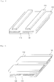
- Fig. 1 is a view illustrating an electrode stacked energy conversion device using liquid (hereinafter referred to as "energy conversion device") according to an exemplary embodiment of the present invention.
- an energy conversion device comprises: a substrate 110, a first electrode 120, an energy conversion layer 140, and a second electrode 130.
- the substrate 110 is a basic element for forming a plurality of element on the upper side thereof in order to implement the energy conversion device.
- the first electrode 120, the energy conversion layer 140, the second electrode 130, and the like can be formed directly or indirectly on the substrate 110. Forming indirectly means that the elements are not formed directly on the substrate 110, but instead, they can be formed on the upper side of the other elements that had already been formed on the substrate 110.
- the energy conversion layer 140, the second electrode 130, and the like can be formed directly on the substrate 110, or formed indirectly on the first electrode 120 that had been formed on the substrate 110, or formed possibly on the energy conversion layer 140 that had been formed on the substrate 110.
- the substrate 110 it is possible to form on the rear surface of the substrate 110 by utilizing the front and rear surfaces of the substrate 110. That is, although forming the elements on the upper surface of the substrate 110 is illustrated in the present exemplary embodiment as an example, but instead, forming respectively on the front and rear surfaces with respect to the substrate 110 is also possible depending on the cases.
- the first electrode 120 is formed on the substrate 110 as described above. In forming on the substrate 110, it is possible to form so as to cover all of the substrate 110 across the entire front surface of the substrate 110, and it is also possible to form on a portion thereof as shown in Fig. 1 .
- the energy conversion layer 140 can be formed on the first electrode 120 formed on the substrate 110 in a way that it covers the first electrode 120 as shown in Fig. 1 .
- the energy conversion layer 140 is formed to cover the first electrode 120 in order to prevent electrical short of the first electrode 120.
- the energy conversion layer 140 is composed by stacking an inorganic material layer and/or an organic material layer.
- forming of such energy conversion layer 140 can be formed by using processes such as vacuum deposition, spin coating, and spraying, and more than one separated body can be formed through the patterning process.
- the energy conversion layer 140 may comprise an organic layer 230 containing at least one material of Poly(methyl methacrylate) (PMMA), Polyethylene (PE), Polystyrene (PS), Polyvinylpyrrolidone (PVP), Poly(4-vinylpenol) (PVP), or Polyethersulfone (PES), Poly(4-methoxyphenyl acrylate) (PMPA), Poly(phenyl acrylate) (PPA), Poly(2,2,2-trifluoroethyl methacrylate) (PTFMA), cyanoethylpullulan (CYEPL), Polyvinyl chloride (PVC), Poly(parabanic acid) resin (PPA), Poly(t-butylstyrene) (PTBS), Polythienylenevinylene (PTV), Polyvinyl acetate (PVA), Poly(vinyl alcohol) (PVA), Poly(r-methylstyrene) (PAMS), Poly(vinyl alcohol)-co-pol
- polytetrafluoroethylene ethylene-tetrafluoroethylene
- FEP fluorinated ethylene propylene
- a material having a dielectric constant (K) equal to or less than 4 can be used for the organic material layer, and a material having a dielectric constant (K) greater than 5 can be used for the inorganic material layer.
- the second electrode 130 of the present exemplary embodiment is formed on the energy conversion layer 140 so that it is overlapped with the first electrode 120 along the vertical direction, and its contact state with respect to the liquid is changing depending on the movement or the state change of the liquid.
- the above described energy conversion device generates energy according to the change of the contact state of the second electrode 130 or the energy conversion layer 140 with the liquid in accordance with the movement or the state change of the liquid.
- the second electrode 130 can be formed overlapped with the first electrode 120.
- the second electrode 130 is entirely overlapped with the first electrode 120 as illustrated in Figs. 1 to 3 , they can be partially overlapped as illustrated in Fig. 4 or Fig. 5 .
- the first electrode 120 and the second electrode 130 of the energy conversion device according to the present exemplary embodiment are not formed in the same planar surface, or formed separately spaced apart with a predetermined distance along the horizontal direction, but instead, they are formed partially or entirely overlapped with each other along the vertical direction.
- the present invention since it is a structure wherein the second electrode 130 and the first electrode 120 are located respectively in the upper side and the lower side of the energy conversion layer 140 which is located between them, the present invention has a structure wherein integration is more facilitated than the energy generation device having a planar structure as shown in Fig. 6 .
- the electrode may be: an inorganic electrode comprising at least any one of ITO, IGO, chrome, aluminum, indium zinc oxide (IZO), indium gallium zinc oxide (IGZO), ZnO, ZnO 2 or TiO 2 ; or a metal electrode comprising at least any one of platinum, gold, silver, aluminum, iron or copper; or an organic electrode comprising at least any one of polyethylenedioxythiophene (PEDOT), carbon nano tube (CNT), graphene, polyacetylene, polythiophene (PT), polypyrrole, polyparaphenylene (PPV), polyanilinep), poly sulfur nitride, stainless steel, iron alloy containing more than 10% of crome, SUS 304, SUS 316, SUS 316L, Co-Cr alloy, Ti alloy, nitinol (Ni-Ti) or polyparaphenylenevinylene.
- PEDOT polyethylenedioxythiophene
- CNT carbon nano tube
- PT polyacetylene
- the energy conversion device according to the present exemplary embodiment may further comprise a hydrophobic material layer.
- the shape of the liquid according to the present exemplary embodiment is changed as the contact surface, the contact angle, or the contact area with respect to the second electrode 130 or the first electrode 120 is changed, therefore, in order to restore such deformation into its original shape, the hydrophobic material layer 150 is stacked on the electrode.
- the hydrophobic material layer 150 may comprise at least any one or the mixture of silane series material, fluoropolymer material, trichlorosilane, trimethoxysilane, pentafluorophenylpropyltrichlorosilane, (benzyloxy)alkyltrimethoxysilane (BSM-22), (benzyloxy)alkyltrichlorosilane (BTS), hexamethyldisilazane (HMDS), octadecyltrichlorosilane (OTS), octadecyltrimethoxysilane (OTMS), and divinyltetramethyldisiloxane-bis(benzocyclobutene) (BCB).
- silane series material trichlorosilane, trimethoxysilane, pentafluorophenylpropyltrichlorosilane, (benzyloxy)alkyltrimethoxysilane (BSM
- the energy conversion device according to the present exemplary embodiment may further comprise an insulating layer 160. That is, the second electrode 130 is insulated by the insulating layer 160, thereby enhancing the electrical stability of the energy conversion device implemented in accordance with the present exemplary embodiment.
- the energy conversion device may further comprise a second energy conversion layer 170 formed on the second electrode 130 and covering the second electrode 130.
- the second energy conversion layer 170 is additionally formed on the second electrode 130 together with the first energy conversion layer 140 formed on the first electrode 120.
- hydrophobic material layer 150 can be omitted when the second energy conversion layer 170 is a hydrophobic material.
- the first electrode 120 of the present exemplary embodiment can include a plurality of first electrodes spaced apart from each other with a predetermined distance from one another along a certain direction.
- the energy conversion layer 140 is stacked on the first electrode 120, and the second electrode 130 can be formed overlapped with the first electrode 120 along the vertical direction while the energy conversion layer 140 is interposed therebetween.
- a potential difference occurs between the first electrode 120 and the second electrode 130 formed on the first electrode 120, and energy can be generated through this potential difference.
- the plurality of the first electrodes and the plurality of the second electrodes are formed along the same direction; therefore, a variety of voltages can be generated according to the number of formed electrodes.
- the first electrode 120 of the present exemplary embodiment can include a plurality of first electrodes spaced apart from each other with a predetermined distance along a certain direction.
- the energy conversion layer 140 is stacked on the first electrode 120, and a second electrode 130 can be formed overlapped with the first electrode 120 along the vertical direction while the energy conversion layer 140 is interposed therebetween.
- the second electrode 130 of the present exemplary embodiment is formed along the crossing direction of the first electrode 120.
- the electrodes are arranged along the direction orthogonal to each other as shown in Fig. 5 , thus, a more variety of potential differences between the electrodes, thereby possibly generating a variety of voltages.
- Figs. 4 and 5 exemplary illustrate that each of the first electrode 120 and the second electrode 130 include a plurality of electrodes. However, they can be formed in a way that the first electrode 120 can be formed by a single electrode plate while the second electrode 130 includes a plurality of electrodes spaced apart from one another with a predetermined distance along a certain direction. Or, it is also possible that the second electrode 130 is formed by a single electrode plate while the first electrode 120 includes a plurality of electrodes spaced apart from one another with a predetermined distance along the consistent direction on the substrate.
- the substrate 110 wherein a plurality of elements is formed may possibly comprise a textile material (nylon, cotton, polyester, and the like).
- a textile material nylon, cotton, polyester, and the like.
- a material capable of forming electrode is synthesized to be used as a weft thread and a warp thread which are crossing each other in the cloth, so that energy can be generated from the liquid flow on the substrate 110 made of the cloth.
- the weft thread and the warp thread can be functioned as a first electrode 120 and a second electrode 130 respectively. Also, the weft thread and the warp thread are alternately positioned in the upper and the lower side in a cloth structure, the functions of the first electrode 120 and the second electrode 130 can be performed alternately in the aforementioned exemplary embodiment.
- the energy conversion layer 140 can be formed by the method wherein cloth is inserted during the weaving process of the weft thread and the warp thread.
- the energy conversion device is configured in a structure wherein the second electrode 130 is formed above the first electrode 120, and a hydrophobic material layer 150 is covering it. A liquid drop is flowing over the energy conversion device, and the resulting voltage generation is same as Fig. 8 .
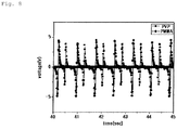
- Fig. 8 is the result of using PMMA and PVP as materials of the energy conversion layer, which enables implementation of an electrical energy generating device having a superior integration property by using the aforementioned electrode structure according to the present invention. And, miniaturization of the device is possible through the vertical electrode structure, and a much higher efficiency energy conversion device can be implemented since a variety of voltages can be generated depending on the numbers of the upper side and the lower side electrodes.
Landscapes
- Engineering & Computer Science (AREA)
- Power Engineering (AREA)
- Physical Or Chemical Processes And Apparatus (AREA)
- Battery Electrode And Active Subsutance (AREA)
- General Electrical Machinery Utilizing Piezoelectricity, Electrostriction Or Magnetostriction (AREA)
- Photovoltaic Devices (AREA)
Abstract
Description
- The present invention relates to an energy conversion device using liquid, more particularly, to an energy conversion device converting the mechanical energy generated by the flow of a liquid into an electrical energy.
- The energy conversion technologies of the prior art for converting mechanical energy into electrical energy use a principle that electrical capacitance is being created in the electrode under a dielectric material by varying the contact surface of a liquid metal which is in contact with a dielectric material in accordance with the flow of time.
- A method and a device for converting energy using a fluid of the prior art is being disclosed in the
U.S. Patent No. 7,898,096 . - In the energy conversion device of the prior art using a fluid, an electrode having a predetermined pattern is formed on the wall having the shape of a thin and long channel, and a dielectric material layer is formed above the electrode. Then, a small waterdrop-like conductive liquid and a non-conductive liquid are being injected into the channel, and the conductive liquid is depolarized by applying a voltage from an external power source to such waterdrop-like conductive liquid.
- At this state, when a physical pressure is applied to a predetermined portion (not shown) which is connected to the channel the depolarized waterdrop-like conductive liquid is moved along the channel, and during this process, the contact surface of the multiple electrodes, which is formed with a consistent pattern, with the moving multiple conductive liquid drop is continuously changing with time, and as a result, an electrical energy is generated due to the electrical capacitance change.
- However, a method and a device of the prior art for converting energy using a fluid have various problems for commercialization.
- First, since the reversible movement, wherein a drop-like liquid metal which has been moved inside the narrow and thin channel is returning back to its original position when the external force is removed, is difficult, there is a limitation in that a separate lubricating layer is required and an inoperable condition happens due to the easy occurrence of channel blocking phenomenon.
- Moreover, since the method and the device of the prior art for converting energy using a fluid adopt a narrow and thin channel structure, the two facing electrodes must be patterned in a predetermined shape on the channel wall making the device configuration complicated due to such a structure, and the size of the module generating electrical energy becomes large, and there has been many limitations in mass production or cost reduction.
- In addition, as for other problems, using a liquid metal such as mercury or galinstan is harmful to the human body and the environment, and there is a limitation in that a separate external power must be applied for depolarizing such a conductive liquid.
- Further, the method and the device of the prior art for converting energy using a fluid have problems in that the reversible movements in the channel structure must be continuously implemented, and the control is difficult since two different kinds of immiscible liquids must be used.
- An objective of the present invention is to provide a method and a device for converting energy using a liquid, especially for generating electrical energy by changing the contact surface between the liquid and the electrodes in the device.
- Another objective of the present invention is to provide an efficient method and a device for converting energy while having a simple structure and a lower failure rate through implementation of a structure wherein electrodes are being stacked using an energy conversion layer.
- For solving aforementioned technical problems, an electrode stacked energy conversion device using a liquid comprises: a substrate; a first electrode formed in the substrate; a first energy conversion layer formed in the first electrode and covering the first electrode; and a second electrode formed on the first energy conversion layer, wherein the contact state of the second electrode with respect to the liquid is being changed according to the movement or the state of the liquid.
- The electrode stacked energy conversion device using a liquid may further comprise a second energy conversion layer formed on the second electrode and covering the second electrode.
- It is preferred that the first electrode includes a plurality of first electrodes formed on the substrate and spaced apart from each other with a predetermined distance along a certain direction.
- It is preferred that the second electrode includes a plurality of second electrodes formed on the energy conversion layer and spaced apart from each other with a predetermined distance along a direction which is crossing the certain direction.
- The first energy conversion layer may comprise at least any one of an inorganic material layer, an organic material layer, and a mixed material layer of organic and inorganic materials.
- It is preferred that a hydrophobic material layer is stacked on the first energy conversion layer so that the shape of the ionic liquid or water can be restored.
- It is preferred that an insulation layer is formed between the hydrophobic material layer and the second electrode.
- An electric energy generating device having a superior integrating property can be implemented through the electrode structure according to the present invention, and miniaturization of the device becomes possible through the vertical electrode structure, and the various voltages can be generated according to the number of the upper and the lower electrodes, and therefore a high efficiency energy conversion device can be implemented.
-
-
Figs. 1 to 3 are the cross-sectional views of the electrode stacked energy conversion devices using liquid according to an exemplary embodiment of the present invention. -
Figs. 4 to 5 are the views of the electrode stacked energy conversion devices using liquid according to an exemplary embodiment of the present invention. -
Fig. 6 is a view illustrating integration of an electrode stacked energy conversion devices using liquid according to an exemplary embodiment of the present invention. -
Fig. 7 is a view of an electrode stacked energy conversion devices using liquid according to an exemplary embodiment of the present invention. -
Fig. 8 is a view illustrating an experiment example of an electrode stacked energy conversion devices using liquid according to an exemplary embodiment of the present invention. - Contents of the description below merely exemplify the principle of the invention. Therefore those of ordinary skill i n the art may implement the theory of the invention and invent various apparatuses which are included within the concept and the scope of the invention even though it is not clearly explained or illustrated in the description. Furthermore, in principle, all the conditional terms and embodiments listed in this description are clearly intended for the purpose of understanding the concept of the invention, and one should understand that this invention is not limited to such specially listed exemplary embodiments and the conditions.
- The above described objectives, features, and advantages will be more apparent through the following detailed description related to the accompanying drawings, and thus tho se of ordinary skill in the art may easily implement the technical spirit of the invention.
- A detailed description of a publicly known prior art related to the present invention will be omitted if determined that it may unnecessarily obscure the gist of the present invention. Hereinafter, a preferred exemplary embodiment according to the present invention will be described in detail with reference to the accompanying drawings.
-
Fig. 1 is a view illustrating an electrode stacked energy conversion device using liquid (hereinafter referred to as "energy conversion device") according to an exemplary embodiment of the present invention. - Referring to
Fig. 1 , an energy conversion device according to an exemplary embodiment of the present invention comprises: asubstrate 110, afirst electrode 120, anenergy conversion layer 140, and asecond electrode 130. - The
substrate 110 according to an exemplary embodiment of the present invention is a basic element for forming a plurality of element on the upper side thereof in order to implement the energy conversion device. In the present exemplary embodiment, thefirst electrode 120, theenergy conversion layer 140, thesecond electrode 130, and the like can be formed directly or indirectly on thesubstrate 110. Forming indirectly means that the elements are not formed directly on thesubstrate 110, but instead, they can be formed on the upper side of the other elements that had already been formed on thesubstrate 110. - In other words, in the exemplary embodiment of the present invention, the
energy conversion layer 140, thesecond electrode 130, and the like can be formed directly on thesubstrate 110, or formed indirectly on thefirst electrode 120 that had been formed on thesubstrate 110, or formed possibly on theenergy conversion layer 140 that had been formed on thesubstrate 110. - Also, it is possible to form on the rear surface of the
substrate 110 by utilizing the front and rear surfaces of thesubstrate 110. That is, although forming the elements on the upper surface of thesubstrate 110 is illustrated in the present exemplary embodiment as an example, but instead, forming respectively on the front and rear surfaces with respect to thesubstrate 110 is also possible depending on the cases. - In the present exemplary embodiment, the
first electrode 120 is formed on thesubstrate 110 as described above. In forming on thesubstrate 110, it is possible to form so as to cover all of thesubstrate 110 across the entire front surface of thesubstrate 110, and it is also possible to form on a portion thereof as shown inFig. 1 . - In addition, it is also possible to be formed as a single element, and it is also possible to be formed as two electrodes having a predetermined gap therebetween as shown in
Fig. 4 . Further, it is also possible that a plurality of electrodes is patterned on thesubstrate 110 according to the predetermined gap or the shape thereof. - In the present exemplary embodiment, the
energy conversion layer 140 can be formed on thefirst electrode 120 formed on thesubstrate 110 in a way that it covers thefirst electrode 120 as shown inFig. 1 . Preferably, theenergy conversion layer 140 is formed to cover thefirst electrode 120 in order to prevent electrical short of thefirst electrode 120. - In the present exemplary embodiment, the
energy conversion layer 140 is composed by stacking an inorganic material layer and/or an organic material layer. Preferably, forming of suchenergy conversion layer 140 can be formed by using processes such as vacuum deposition, spin coating, and spraying, and more than one separated body can be formed through the patterning process. - Also, the
energy conversion layer 140 may comprise an organic layer 230 containing at least one material of Poly(methyl methacrylate) (PMMA), Polyethylene (PE), Polystyrene (PS), Polyvinylpyrrolidone (PVP), Poly(4-vinylpenol) (PVP), or Polyethersulfone (PES), Poly(4-methoxyphenyl acrylate) (PMPA), Poly(phenyl acrylate) (PPA), Poly(2,2,2-trifluoroethyl methacrylate) (PTFMA), cyanoethylpullulan (CYEPL), Polyvinyl chloride (PVC), Poly(parabanic acid) resin (PPA), Poly(t-butylstyrene) (PTBS), Polythienylenevinylene (PTV), Polyvinyl acetate (PVA), Poly(vinyl alcohol) (PVA), Poly(r-methylstyrene) (PAMS), Poly(vinyl alcohol)-co-poly(vinyl acetate)-co-poly(itaconic acid) (PVAIA), Polyolefin, Polyacrylate, Parylene-C, Polyimide, octadecyltrichlorosilane (OTS), Poly(triarylamine) (PTTA), Poly-3-hexylthiophene (P3HT), cross-linked Poly-4-vinylphenol (cross-linked PVP), Poly(perfluoroalkenyl vinyl ether), Nylon-6, n-Octadecylphosphonic acid (ODPA), Polytetrafluoroethylene, PTFE), silicone, polyurethane, latex, cellulose acetate, Poly(hydroxy ethyl methacrylate) (PHEMA), Polylactide (PLA), Polyglycolide (PGA), or Poly(glycolide-co-lactide) (PGLA); and an inorganic material layer containing at least one material from silicon dioxide (SiO2), titanium dioxide (TiO2), aluminum oxide (Al2O3), tantalum pentoxide (Ta2O5), zinc oxide (ZnO), yttrium oxide (Y2O3), cerium oxide (CeO2), barium titanate (BaTiO3), barium zirconate titanate (BZT), zirconium dioxide (ZrO2), lanthanum oxide (La2O3), hafnium (HfSiO4), lanthanum aluminate (LaAlO3), silicon nitride (Si3N4), and as for perovskite materials, strontium titanate (SrTiO3), barium strontium titanate (BST), lead zirconate titanate (PZT), calcium copper titanate (CCTO), hafnium oxide (HfO2), apatite (A10(MO4)6X2), hydroxyapatite (Ca10 (PO4)6(OH)2), tricalcium phosphates (Ca3(PO4)2), Na2O-CaO-SiO2, or bioglass (CaO-SiO2-P2O5). - Further, it is also possible to use polytetrafluoroethylene, ethylene-tetrafluoroethylene, fluorinated ethylene propylene (FEP), and perfluoroalkoxy copolymer.
- Preferably, a material having a dielectric constant (K) equal to or less than 4 can be used for the organic material layer, and a material having a dielectric constant (K) greater than 5 can be used for the inorganic material layer.
- The
second electrode 130 of the present exemplary embodiment is formed on theenergy conversion layer 140 so that it is overlapped with thefirst electrode 120 along the vertical direction, and its contact state with respect to the liquid is changing depending on the movement or the state change of the liquid. - The above described energy conversion device according to the present exemplary embodiment generates energy according to the change of the contact state of the
second electrode 130 or theenergy conversion layer 140 with the liquid in accordance with the movement or the state change of the liquid. - In other words, as the liquid flows above the first or the
second electrode 130, the change in the capacitance occurs due to the resulting change of the contact state, and a potential difference is produced thereby. Thus, energy can be generated from the movement of electrons trying to compensate the aforementioned potential difference. - Thus, as shown in
Figs. 1 to 3 , thesecond electrode 130 can be formed overlapped with thefirst electrode 120. Although thesecond electrode 130 is entirely overlapped with thefirst electrode 120 as illustrated inFigs. 1 to 3 , they can be partially overlapped as illustrated inFig. 4 or Fig. 5 . - The
first electrode 120 and thesecond electrode 130 of the energy conversion device according to the present exemplary embodiment are not formed in the same planar surface, or formed separately spaced apart with a predetermined distance along the horizontal direction, but instead, they are formed partially or entirely overlapped with each other along the vertical direction. - That is, since it is a structure wherein the
second electrode 130 and thefirst electrode 120 are located respectively in the upper side and the lower side of theenergy conversion layer 140 which is located between them, the present invention has a structure wherein integration is more facilitated than the energy generation device having a planar structure as shown inFig. 6 . - In the above described description, the electrode may be: an inorganic electrode comprising at least any one of ITO, IGO, chrome, aluminum, indium zinc oxide (IZO), indium gallium zinc oxide (IGZO), ZnO, ZnO2 or TiO2; or a metal electrode comprising at least any one of platinum, gold, silver, aluminum, iron or copper; or an organic electrode comprising at least any one of polyethylenedioxythiophene (PEDOT), carbon nano tube (CNT), graphene, polyacetylene, polythiophene (PT), polypyrrole, polyparaphenylene (PPV), polyanilinep), poly sulfur nitride, stainless steel, iron alloy containing more than 10% of crome, SUS 304, SUS 316, SUS 316L, Co-Cr alloy, Ti alloy, nitinol (Ni-Ti) or polyparaphenylenevinylene.
- Further, the energy conversion device according to the present exemplary embodiment may further comprise a hydrophobic material layer. The shape of the liquid according to the present exemplary embodiment is changed as the contact surface, the contact angle, or the contact area with respect to the
second electrode 130 or thefirst electrode 120 is changed, therefore, in order to restore such deformation into its original shape, thehydrophobic material layer 150 is stacked on the electrode. - According to the present exemplary embodiment, the
hydrophobic material layer 150 may comprise at least any one or the mixture of silane series material, fluoropolymer material, trichlorosilane, trimethoxysilane, pentafluorophenylpropyltrichlorosilane, (benzyloxy)alkyltrimethoxysilane (BSM-22), (benzyloxy)alkyltrichlorosilane (BTS), hexamethyldisilazane (HMDS), octadecyltrichlorosilane (OTS), octadecyltrimethoxysilane (OTMS), and divinyltetramethyldisiloxane-bis(benzocyclobutene) (BCB). - Also, referring to
Fig. 2 , the energy conversion device according to the present exemplary embodiment may further comprise aninsulating layer 160. That is, thesecond electrode 130 is insulated by the insulatinglayer 160, thereby enhancing the electrical stability of the energy conversion device implemented in accordance with the present exemplary embodiment. - Next, referring to
Fig. 3 , the energy conversion device according to the present exemplary embodiment may further comprise a secondenergy conversion layer 170 formed on thesecond electrode 130 and covering thesecond electrode 130. - In other words, it is also possible that the second
energy conversion layer 170 is additionally formed on thesecond electrode 130 together with the firstenergy conversion layer 140 formed on thefirst electrode 120. - Also, although further forming of a
hydrophobic material layer 150 on the secondenergy conversion layer 170 is illustrated inFig. 3 , it is also possible that thehydrophobic material layer 150 can be omitted when the secondenergy conversion layer 170 is a hydrophobic material. - Hereinafter, the structure of the energy conversion device capable of generating much higher capacity energy by using the energy conversion device according to the aforementioned exemplary embodiment will be described with reference to
Fig. 4 or Fig. 5 . - Referring to
Fig. 4 , thefirst electrode 120 of the present exemplary embodiment can include a plurality of first electrodes spaced apart from each other with a predetermined distance from one another along a certain direction. - Also, the
energy conversion layer 140 is stacked on thefirst electrode 120, and thesecond electrode 130 can be formed overlapped with thefirst electrode 120 along the vertical direction while theenergy conversion layer 140 is interposed therebetween. - In the structure of the present exemplary embodiment, a potential difference occurs between the
first electrode 120 and thesecond electrode 130 formed on thefirst electrode 120, and energy can be generated through this potential difference. In the present exemplary embodiment, the plurality of the first electrodes and the plurality of the second electrodes are formed along the same direction; therefore, a variety of voltages can be generated according to the number of formed electrodes. - Next, referring to
Fig. 5 , thefirst electrode 120 of the present exemplary embodiment can include a plurality of first electrodes spaced apart from each other with a predetermined distance along a certain direction. - Also, the
energy conversion layer 140 is stacked on thefirst electrode 120, and asecond electrode 130 can be formed overlapped with thefirst electrode 120 along the vertical direction while theenergy conversion layer 140 is interposed therebetween. However, unlike theFig. 4 thesecond electrode 130 of the present exemplary embodiment is formed along the crossing direction of thefirst electrode 120. - That is, the electrodes are arranged along the direction orthogonal to each other as shown in
Fig. 5 , thus, a more variety of potential differences between the electrodes, thereby possibly generating a variety of voltages. - Further,
Figs. 4 and 5 exemplary illustrate that each of thefirst electrode 120 and thesecond electrode 130 include a plurality of electrodes. However, they can be formed in a way that thefirst electrode 120 can be formed by a single electrode plate while thesecond electrode 130 includes a plurality of electrodes spaced apart from one another with a predetermined distance along a certain direction. Or, it is also possible that thesecond electrode 130 is formed by a single electrode plate while thefirst electrode 120 includes a plurality of electrodes spaced apart from one another with a predetermined distance along the consistent direction on the substrate. - Also, in the aforementioned exemplary embodiment, the
substrate 110 wherein a plurality of elements is formed may possibly comprise a textile material (nylon, cotton, polyester, and the like). At this time, it is also possible that by applying the configuration same asFig. 5 to the weaving structure of a cloth (that is, a textile) wherein a material capable of forming electrode is synthesized to be used as a weft thread and a warp thread which are crossing each other in the cloth, so that energy can be generated from the liquid flow on thesubstrate 110 made of the cloth. - At this time, the weft thread and the warp thread can be functioned as a
first electrode 120 and asecond electrode 130 respectively. Also, the weft thread and the warp thread are alternately positioned in the upper and the lower side in a cloth structure, the functions of thefirst electrode 120 and thesecond electrode 130 can be performed alternately in the aforementioned exemplary embodiment. - Also, the
energy conversion layer 140 can be formed by the method wherein cloth is inserted during the weaving process of the weft thread and the warp thread. - The result of voltage generated through the energy conversion device according to the aforementioned present invention will be described with reference to
Figs. 7 and8 . - Referring to
Fig. 7 , the energy conversion device is configured in a structure wherein thesecond electrode 130 is formed above thefirst electrode 120, and ahydrophobic material layer 150 is covering it. A liquid drop is flowing over the energy conversion device, and the resulting voltage generation is same asFig. 8 . -
Fig. 8 is the result of using PMMA and PVP as materials of the energy conversion layer, which enables implementation of an electrical energy generating device having a superior integration property by using the aforementioned electrode structure according to the present invention. And, miniaturization of the device is possible through the vertical electrode structure, and a much higher efficiency energy conversion device can be implemented since a variety of voltages can be generated depending on the numbers of the upper side and the lower side electrodes. - Above description is merely an exemplary description of the technical spirit of the present invention, and various modifications, changes, and substitutions are possible for a person of skill in the art within the scope without deviating from the fundamental characteristics of the present invention.
- Therefore, the exemplary embodiment and the accompanying drawings disclosed in the present invention is for explanation and not for limiting the technical spirit of the present invention, and the scope of the technical spirit of the present invention is not limited by these exemplary embodiments and the accompanying drawings. The scope of protection of the present invention must be interpreted according to the following claims, and it must be interpreted in such a way that all the technical spirits within the equivalent scope of the present invention are included in the scope of the rights of the present invention.
Claims (9)
- An electrode stacked energy conversion device using a liquid comprising:a substrate;a first electrode formed in the substrate;a first energy conversion layer formed in the first electrode and covering the first electrode; anda second electrode formed on the first energy conversion layer, wherein contact state of the second electrode with respect to the liquid is being changed according to movement or state of the liquid.
- The electrode stacked energy conversion device using a liquid according to claim 1,
further comprising a second energy conversion layer formed on the second electrode and covering the second electrode. - The electrode stacked energy conversion device using a liquid according to claim 1, wherein
the first electrode is arranged and includes a plurality of first electrodes formed on the substrate and spaced apart from each other with a predetermined distance along a certain direction. - The electrode stacked energy conversion device using a liquid according to claim 3, wherein
the second electrode is arranged and includes a plurality of second electrodes formed on the energy conversion layer and spaced apart from each other with a predetermined distance along a direction which is crossing the certain direction. - The electrode stacked energy conversion device using a liquid according to claim 1, wherein
the first energy conversion layer comprises at least any one of an inorganic material layer, an organic material layer, and a mixed material layer of organic and inorganic materials. - The electrode stacked energy conversion device using a liquid according to claim 2, wherein
a hydrophobic material layer is stacked on the first energy conversion layer so that shape of ionic liquid or water is capable of being restored. - The electrode stacked energy conversion device using a liquid according to claim 6, wherein
an insulating layer is formed between the hydrophobic material layer and the second electrode. - The electrode stacked energy conversion device using a liquid according to claim 1, wherein
the first electrode is formed in a single electrode plate while the second electrode includes a plurality of electrodes formed on the energy conversion layer and spaced apart from one another with a predetermined distance along a certain direction. - The electrode stacked energy conversion device using a liquid according to claim 1, wherein
the second electrode is formed by a single electrode plate while the first electrode includes a plurality of electrodes formed on the substrate and spaced apart from one another with a predetermined distance along a certain direction.
Applications Claiming Priority (2)
| Application Number | Priority Date | Filing Date | Title |
|---|---|---|---|
| KR1020140089202A KR101988876B1 (en) | 2014-07-15 | 2014-07-15 | Layered apparatus for energy converting using liquid |
| PCT/KR2015/005838 WO2016010263A1 (en) | 2014-07-15 | 2015-06-10 | Electrode laminate structure energy conversion apparatus using liquid |
Publications (3)
| Publication Number | Publication Date |
|---|---|
| EP3171416A1 true EP3171416A1 (en) | 2017-05-24 |
| EP3171416A4 EP3171416A4 (en) | 2018-04-11 |
| EP3171416B1 EP3171416B1 (en) | 2024-08-07 |
Family
ID=55078711
Family Applications (1)
| Application Number | Title | Priority Date | Filing Date |
|---|---|---|---|
| EP15821895.8A Active EP3171416B1 (en) | 2014-07-15 | 2015-06-10 | Use of an electrode stacked energy conversion apparatus for generating electrical energy using liquid |
Country Status (4)
| Country | Link |
|---|---|
| US (1) | US10291153B2 (en) |
| EP (1) | EP3171416B1 (en) |
| KR (1) | KR101988876B1 (en) |
| WO (1) | WO2016010263A1 (en) |
Cited By (1)
| Publication number | Priority date | Publication date | Assignee | Title |
|---|---|---|---|---|
| EP4142139A1 (en) * | 2021-08-27 | 2023-03-01 | Consejo Superior de Investigaciones Científicas (CSIC) | Energy harvesting device and self-powered sensor using the same |
Families Citing this family (4)
| Publication number | Priority date | Publication date | Assignee | Title |
|---|---|---|---|---|
| KR102570652B1 (en) * | 2016-04-26 | 2023-08-23 | 한양대학교 산학협력단 | Reverse Electrowetting-on-Dielectric Energy harvesting Module |
| CN108418472B (en) * | 2018-05-11 | 2023-10-27 | 大连海事大学 | A device and method for generating electricity using liquid droplets |
| KR102585756B1 (en) * | 2018-11-12 | 2023-10-11 | 현대자동차주식회사 | Energy harvesting system based on reverse electro wetting on dielectric |
| KR102877475B1 (en) * | 2023-10-30 | 2025-10-27 | 경희대학교 산학협력단 | Droplet-based electricity generator with high dielectric constant intermediate layer and method of operation thereof |
Family Cites Families (25)
| Publication number | Priority date | Publication date | Assignee | Title |
|---|---|---|---|---|
| US6011346A (en) * | 1998-07-10 | 2000-01-04 | Halliburton Energy Services, Inc. | Apparatus and method for generating electricity from energy in a flowing stream of fluid |
| US6424079B1 (en) * | 1998-08-28 | 2002-07-23 | Ocean Power Technologies, Inc. | Energy harvesting eel |
| EP1212800B1 (en) * | 1999-07-20 | 2007-12-12 | Sri International | Electroactive polymer generators |
| AU2001297790B2 (en) * | 2000-10-25 | 2006-10-12 | Washington State University Research Foundation | Piezoelectric micro-transducers, methods of use and manufacturing methods for same |
| US20050206275A1 (en) * | 2002-01-18 | 2005-09-22 | Radziemski Leon J | Apparatus and method to generate electricity |
| KR100619710B1 (en) * | 2004-12-27 | 2006-09-08 | 엘지전자 주식회사 | Bi-Paper Panels with Improved Electrodes |
| US20070125176A1 (en) * | 2005-12-02 | 2007-06-07 | Honeywell International, Inc. | Energy harvesting device and methods |
| US8003982B2 (en) * | 2005-12-20 | 2011-08-23 | Georgia Tech Research Corporation | Stacked mechanical nanogenerator comprising piezoelectric semiconducting nanostructures and Schottky conductive contacts |
| US7859171B2 (en) * | 2006-10-10 | 2010-12-28 | Micallef Joseph A | Piezoelectric ultracapacitor |
| FR2912568B1 (en) * | 2007-02-08 | 2010-02-12 | Commissariat Energie Atomique | MECHANICAL ENERGY CONVERSION DEVICE FOR IMPACTS IN ELECTRICAL ENERGY WITH OPTIMIZED YIELD |
| WO2008147568A1 (en) * | 2007-05-24 | 2008-12-04 | Digital Biosystems | Electrowetting based digital microfluidics |
| US7898096B1 (en) * | 2007-08-22 | 2011-03-01 | Thomas Nikita Krupenkin | Method and apparatus for energy harvesting using microfluidics |
| JP5616130B2 (en) * | 2009-06-08 | 2014-10-29 | 富士フイルム株式会社 | Piezoelectric element, piezoelectric actuator including the same, liquid ejection device, and power generation device |
| US8926065B2 (en) * | 2009-08-14 | 2015-01-06 | Advanced Liquid Logic, Inc. | Droplet actuator devices and methods |
| KR101588318B1 (en) * | 2009-11-23 | 2016-01-25 | 삼성전자주식회사 | Tubular piezoelectric energy generating device and manufacturing method thereof |
| KR20110062778A (en) * | 2009-12-04 | 2011-06-10 | 삼성전기주식회사 | Inkjet head |
| KR101358291B1 (en) * | 2012-10-31 | 2014-02-12 | 서울대학교산학협력단 | Apparatus for energy harvesting using change of wetting angle and contact area of liquid |
| KR101407489B1 (en) | 2012-11-29 | 2014-06-13 | 서울대학교산학협력단 | Apparatus for energy converting using liquid |
| KR102051518B1 (en) * | 2013-01-28 | 2019-12-03 | 삼성전자주식회사 | Energy harvesting device combined with self-powered touch sensor |
| KR101411337B1 (en) * | 2013-02-15 | 2014-06-25 | 전자부품연구원 | Apparatus having a stacked structure for energy converting using liquid |
| US20160111980A1 (en) * | 2013-06-21 | 2016-04-21 | Agency For Science, Technology And Research | Energy harvesting device and method of harvesting energy |
| US9444031B2 (en) * | 2013-06-28 | 2016-09-13 | Samsung Electronics Co., Ltd. | Energy harvester using mass and mobile device including the energy harvester |
| KR20170032100A (en) * | 2015-09-14 | 2017-03-22 | 삼성전자주식회사 | Energy harvesting apparatus and electronic apparatus having the same |
| US10825614B2 (en) * | 2015-12-17 | 2020-11-03 | Samsung Electronics Co., Ltd. | Energy harvesting device using electroactive polymer nanocomposites |
| JPWO2017119497A1 (en) * | 2016-01-08 | 2018-12-27 | 正毅 千葉 | converter |
-
2014
- 2014-07-15 KR KR1020140089202A patent/KR101988876B1/en active Active
-
2015
- 2015-06-10 WO PCT/KR2015/005838 patent/WO2016010263A1/en not_active Ceased
- 2015-06-10 EP EP15821895.8A patent/EP3171416B1/en active Active
-
2017
- 2017-01-13 US US15/406,577 patent/US10291153B2/en active Active
Cited By (2)
| Publication number | Priority date | Publication date | Assignee | Title |
|---|---|---|---|---|
| EP4142139A1 (en) * | 2021-08-27 | 2023-03-01 | Consejo Superior de Investigaciones Científicas (CSIC) | Energy harvesting device and self-powered sensor using the same |
| WO2023025965A1 (en) | 2021-08-27 | 2023-03-02 | Consejo Superior De Investigaciones Cientificas (Csic) | Energy harvesting device |
Also Published As
| Publication number | Publication date |
|---|---|
| EP3171416B1 (en) | 2024-08-07 |
| US20170149358A1 (en) | 2017-05-25 |
| EP3171416A4 (en) | 2018-04-11 |
| US10291153B2 (en) | 2019-05-14 |
| KR20160008863A (en) | 2016-01-25 |
| KR101988876B1 (en) | 2019-06-13 |
| WO2016010263A1 (en) | 2016-01-21 |
Similar Documents
| Publication | Publication Date | Title |
|---|---|---|
| US10270370B2 (en) | Energy conversion substrate using liquid | |
| EP2930359B1 (en) | Energy conversion device using liquid | |
| US10291153B2 (en) | Electrode stacked energy conversion device using liquid | |
| US10050567B2 (en) | Flexible energy conversion device using liquid | |
| EP2924869B1 (en) | Energy conversion device using change of contact surface with liquid | |
| EP2838191B1 (en) | Energy conversion device using change of contact area and contact angle of liquid | |
| KR101411337B1 (en) | Apparatus having a stacked structure for energy converting using liquid | |
| CN111181443B (en) | Energy harvesting system based on reverse electrowetting on dielectrics | |
| KR101721662B1 (en) | Liquid drop measuring device | |
| KR101468642B1 (en) | Rotating-type Apparatus for energy converting using liquid | |
| KR101403017B1 (en) | Apparatus having a through hole for energy converting using liquid | |
| KR20170013669A (en) | Self powered lighting module using liquid |
Legal Events
| Date | Code | Title | Description |
|---|---|---|---|
| STAA | Information on the status of an ep patent application or granted ep patent |
Free format text: STATUS: THE INTERNATIONAL PUBLICATION HAS BEEN MADE |
|
| PUAI | Public reference made under article 153(3) epc to a published international application that has entered the european phase |
Free format text: ORIGINAL CODE: 0009012 |
|
| STAA | Information on the status of an ep patent application or granted ep patent |
Free format text: STATUS: REQUEST FOR EXAMINATION WAS MADE |
|
| 17P | Request for examination filed |
Effective date: 20170112 |
|
| AK | Designated contracting states |
Kind code of ref document: A1 Designated state(s): AL AT BE BG CH CY CZ DE DK EE ES FI FR GB GR HR HU IE IS IT LI LT LU LV MC MK MT NL NO PL PT RO RS SE SI SK SM TR |
|
| AX | Request for extension of the european patent |
Extension state: BA ME |
|
| DAV | Request for validation of the european patent (deleted) | ||
| DAX | Request for extension of the european patent (deleted) | ||
| RIN1 | Information on inventor provided before grant (corrected) |
Inventor name: KWON, SOON HYUNG |
|
| A4 | Supplementary search report drawn up and despatched |
Effective date: 20180308 |
|
| RIC1 | Information provided on ipc code assigned before grant |
Ipc: H02N 1/08 20060101AFI20180303BHEP |
|
| STAA | Information on the status of an ep patent application or granted ep patent |
Free format text: STATUS: EXAMINATION IS IN PROGRESS |
|
| 17Q | First examination report despatched |
Effective date: 20200420 |
|
| GRAP | Despatch of communication of intention to grant a patent |
Free format text: ORIGINAL CODE: EPIDOSNIGR1 |
|
| STAA | Information on the status of an ep patent application or granted ep patent |
Free format text: STATUS: GRANT OF PATENT IS INTENDED |
|
| INTG | Intention to grant announced |
Effective date: 20240226 |
|
| GRAS | Grant fee paid |
Free format text: ORIGINAL CODE: EPIDOSNIGR3 |
|
| P01 | Opt-out of the competence of the unified patent court (upc) registered |
Effective date: 20240507 |
|
| GRAA | (expected) grant |
Free format text: ORIGINAL CODE: 0009210 |
|
| STAA | Information on the status of an ep patent application or granted ep patent |
Free format text: STATUS: THE PATENT HAS BEEN GRANTED |
|
| AK | Designated contracting states |
Kind code of ref document: B1 Designated state(s): AL AT BE BG CH CY CZ DE DK EE ES FI FR GB GR HR HU IE IS IT LI LT LU LV MC MK MT NL NO PL PT RO RS SE SI SK SM TR |
|
| REG | Reference to a national code |
Ref country code: GB Ref legal event code: FG4D |
|
| REG | Reference to a national code |
Ref country code: CH Ref legal event code: EP |
|
| REG | Reference to a national code |
Ref country code: IE Ref legal event code: FG4D |
|
| REG | Reference to a national code |
Ref country code: DE Ref legal event code: R096 Ref document number: 602015089469 Country of ref document: DE |
|
| REG | Reference to a national code |
Ref country code: LT Ref legal event code: MG9D |
|
| REG | Reference to a national code |
Ref country code: NL Ref legal event code: MP Effective date: 20240807 |
|
| PG25 | Lapsed in a contracting state [announced via postgrant information from national office to epo] |
Ref country code: NO Free format text: LAPSE BECAUSE OF FAILURE TO SUBMIT A TRANSLATION OF THE DESCRIPTION OR TO PAY THE FEE WITHIN THE PRESCRIBED TIME-LIMIT Effective date: 20241107 |
|
| REG | Reference to a national code |
Ref country code: AT Ref legal event code: MK05 Ref document number: 1712033 Country of ref document: AT Kind code of ref document: T Effective date: 20240807 |
|
| PG25 | Lapsed in a contracting state [announced via postgrant information from national office to epo] |
Ref country code: FI Free format text: LAPSE BECAUSE OF FAILURE TO SUBMIT A TRANSLATION OF THE DESCRIPTION OR TO PAY THE FEE WITHIN THE PRESCRIBED TIME-LIMIT Effective date: 20240807 Ref country code: NL Free format text: LAPSE BECAUSE OF FAILURE TO SUBMIT A TRANSLATION OF THE DESCRIPTION OR TO PAY THE FEE WITHIN THE PRESCRIBED TIME-LIMIT Effective date: 20240807 Ref country code: PT Free format text: LAPSE BECAUSE OF FAILURE TO SUBMIT A TRANSLATION OF THE DESCRIPTION OR TO PAY THE FEE WITHIN THE PRESCRIBED TIME-LIMIT Effective date: 20241209 Ref country code: GR Free format text: LAPSE BECAUSE OF FAILURE TO SUBMIT A TRANSLATION OF THE DESCRIPTION OR TO PAY THE FEE WITHIN THE PRESCRIBED TIME-LIMIT Effective date: 20241108 Ref country code: PL Free format text: LAPSE BECAUSE OF FAILURE TO SUBMIT A TRANSLATION OF THE DESCRIPTION OR TO PAY THE FEE WITHIN THE PRESCRIBED TIME-LIMIT Effective date: 20240807 |
|
| PG25 | Lapsed in a contracting state [announced via postgrant information from national office to epo] |
Ref country code: BG Free format text: LAPSE BECAUSE OF FAILURE TO SUBMIT A TRANSLATION OF THE DESCRIPTION OR TO PAY THE FEE WITHIN THE PRESCRIBED TIME-LIMIT Effective date: 20240807 |
|
| PG25 | Lapsed in a contracting state [announced via postgrant information from national office to epo] |
Ref country code: LV Free format text: LAPSE BECAUSE OF FAILURE TO SUBMIT A TRANSLATION OF THE DESCRIPTION OR TO PAY THE FEE WITHIN THE PRESCRIBED TIME-LIMIT Effective date: 20240807 |
|
| PG25 | Lapsed in a contracting state [announced via postgrant information from national office to epo] |
Ref country code: IS Free format text: LAPSE BECAUSE OF FAILURE TO SUBMIT A TRANSLATION OF THE DESCRIPTION OR TO PAY THE FEE WITHIN THE PRESCRIBED TIME-LIMIT Effective date: 20241207 Ref country code: AT Free format text: LAPSE BECAUSE OF FAILURE TO SUBMIT A TRANSLATION OF THE DESCRIPTION OR TO PAY THE FEE WITHIN THE PRESCRIBED TIME-LIMIT Effective date: 20240807 |
|
| PG25 | Lapsed in a contracting state [announced via postgrant information from national office to epo] |
Ref country code: HR Free format text: LAPSE BECAUSE OF FAILURE TO SUBMIT A TRANSLATION OF THE DESCRIPTION OR TO PAY THE FEE WITHIN THE PRESCRIBED TIME-LIMIT Effective date: 20240807 |
|
| PG25 | Lapsed in a contracting state [announced via postgrant information from national office to epo] |
Ref country code: RS Free format text: LAPSE BECAUSE OF FAILURE TO SUBMIT A TRANSLATION OF THE DESCRIPTION OR TO PAY THE FEE WITHIN THE PRESCRIBED TIME-LIMIT Effective date: 20241107 Ref country code: ES Free format text: LAPSE BECAUSE OF FAILURE TO SUBMIT A TRANSLATION OF THE DESCRIPTION OR TO PAY THE FEE WITHIN THE PRESCRIBED TIME-LIMIT Effective date: 20240807 |
|
| PG25 | Lapsed in a contracting state [announced via postgrant information from national office to epo] |
Ref country code: RS Free format text: LAPSE BECAUSE OF FAILURE TO SUBMIT A TRANSLATION OF THE DESCRIPTION OR TO PAY THE FEE WITHIN THE PRESCRIBED TIME-LIMIT Effective date: 20241107 Ref country code: PT Free format text: LAPSE BECAUSE OF FAILURE TO SUBMIT A TRANSLATION OF THE DESCRIPTION OR TO PAY THE FEE WITHIN THE PRESCRIBED TIME-LIMIT Effective date: 20241209 Ref country code: PL Free format text: LAPSE BECAUSE OF FAILURE TO SUBMIT A TRANSLATION OF THE DESCRIPTION OR TO PAY THE FEE WITHIN THE PRESCRIBED TIME-LIMIT Effective date: 20240807 Ref country code: NO Free format text: LAPSE BECAUSE OF FAILURE TO SUBMIT A TRANSLATION OF THE DESCRIPTION OR TO PAY THE FEE WITHIN THE PRESCRIBED TIME-LIMIT Effective date: 20241107 Ref country code: NL Free format text: LAPSE BECAUSE OF FAILURE TO SUBMIT A TRANSLATION OF THE DESCRIPTION OR TO PAY THE FEE WITHIN THE PRESCRIBED TIME-LIMIT Effective date: 20240807 Ref country code: LV Free format text: LAPSE BECAUSE OF FAILURE TO SUBMIT A TRANSLATION OF THE DESCRIPTION OR TO PAY THE FEE WITHIN THE PRESCRIBED TIME-LIMIT Effective date: 20240807 Ref country code: IS Free format text: LAPSE BECAUSE OF FAILURE TO SUBMIT A TRANSLATION OF THE DESCRIPTION OR TO PAY THE FEE WITHIN THE PRESCRIBED TIME-LIMIT Effective date: 20241207 Ref country code: HR Free format text: LAPSE BECAUSE OF FAILURE TO SUBMIT A TRANSLATION OF THE DESCRIPTION OR TO PAY THE FEE WITHIN THE PRESCRIBED TIME-LIMIT Effective date: 20240807 Ref country code: GR Free format text: LAPSE BECAUSE OF FAILURE TO SUBMIT A TRANSLATION OF THE DESCRIPTION OR TO PAY THE FEE WITHIN THE PRESCRIBED TIME-LIMIT Effective date: 20241108 Ref country code: FI Free format text: LAPSE BECAUSE OF FAILURE TO SUBMIT A TRANSLATION OF THE DESCRIPTION OR TO PAY THE FEE WITHIN THE PRESCRIBED TIME-LIMIT Effective date: 20240807 Ref country code: ES Free format text: LAPSE BECAUSE OF FAILURE TO SUBMIT A TRANSLATION OF THE DESCRIPTION OR TO PAY THE FEE WITHIN THE PRESCRIBED TIME-LIMIT Effective date: 20240807 Ref country code: BG Free format text: LAPSE BECAUSE OF FAILURE TO SUBMIT A TRANSLATION OF THE DESCRIPTION OR TO PAY THE FEE WITHIN THE PRESCRIBED TIME-LIMIT Effective date: 20240807 Ref country code: AT Free format text: LAPSE BECAUSE OF FAILURE TO SUBMIT A TRANSLATION OF THE DESCRIPTION OR TO PAY THE FEE WITHIN THE PRESCRIBED TIME-LIMIT Effective date: 20240807 |
|
| PG25 | Lapsed in a contracting state [announced via postgrant information from national office to epo] |
Ref country code: SM Free format text: LAPSE BECAUSE OF FAILURE TO SUBMIT A TRANSLATION OF THE DESCRIPTION OR TO PAY THE FEE WITHIN THE PRESCRIBED TIME-LIMIT Effective date: 20240807 Ref country code: RO Free format text: LAPSE BECAUSE OF FAILURE TO SUBMIT A TRANSLATION OF THE DESCRIPTION OR TO PAY THE FEE WITHIN THE PRESCRIBED TIME-LIMIT Effective date: 20240807 Ref country code: DK Free format text: LAPSE BECAUSE OF FAILURE TO SUBMIT A TRANSLATION OF THE DESCRIPTION OR TO PAY THE FEE WITHIN THE PRESCRIBED TIME-LIMIT Effective date: 20240807 |
|
| PG25 | Lapsed in a contracting state [announced via postgrant information from national office to epo] |
Ref country code: EE Free format text: LAPSE BECAUSE OF FAILURE TO SUBMIT A TRANSLATION OF THE DESCRIPTION OR TO PAY THE FEE WITHIN THE PRESCRIBED TIME-LIMIT Effective date: 20240807 |
|
| PG25 | Lapsed in a contracting state [announced via postgrant information from national office to epo] |
Ref country code: CZ Free format text: LAPSE BECAUSE OF FAILURE TO SUBMIT A TRANSLATION OF THE DESCRIPTION OR TO PAY THE FEE WITHIN THE PRESCRIBED TIME-LIMIT Effective date: 20240807 |
|
| PG25 | Lapsed in a contracting state [announced via postgrant information from national office to epo] |
Ref country code: SK Free format text: LAPSE BECAUSE OF FAILURE TO SUBMIT A TRANSLATION OF THE DESCRIPTION OR TO PAY THE FEE WITHIN THE PRESCRIBED TIME-LIMIT Effective date: 20240807 |
|
| REG | Reference to a national code |
Ref country code: DE Ref legal event code: R097 Ref document number: 602015089469 Country of ref document: DE |
|
| PLBE | No opposition filed within time limit |
Free format text: ORIGINAL CODE: 0009261 |
|
| STAA | Information on the status of an ep patent application or granted ep patent |
Free format text: STATUS: NO OPPOSITION FILED WITHIN TIME LIMIT |
|
| 26N | No opposition filed |
Effective date: 20250508 |
|
| PG25 | Lapsed in a contracting state [announced via postgrant information from national office to epo] |
Ref country code: SE Free format text: LAPSE BECAUSE OF FAILURE TO SUBMIT A TRANSLATION OF THE DESCRIPTION OR TO PAY THE FEE WITHIN THE PRESCRIBED TIME-LIMIT Effective date: 20240807 |
|
| REG | Reference to a national code |
Ref country code: CH Ref legal event code: H13 Free format text: ST27 STATUS EVENT CODE: U-0-0-H10-H13 (AS PROVIDED BY THE NATIONAL OFFICE) Effective date: 20260127 |
|
| PG25 | Lapsed in a contracting state [announced via postgrant information from national office to epo] |
Ref country code: IT Free format text: LAPSE BECAUSE OF FAILURE TO SUBMIT A TRANSLATION OF THE DESCRIPTION OR TO PAY THE FEE WITHIN THE PRESCRIBED TIME-LIMIT Effective date: 20240807 |
|
| PG25 | Lapsed in a contracting state [announced via postgrant information from national office to epo] |
Ref country code: MC Free format text: LAPSE BECAUSE OF FAILURE TO SUBMIT A TRANSLATION OF THE DESCRIPTION OR TO PAY THE FEE WITHIN THE PRESCRIBED TIME-LIMIT Effective date: 20240807 |
|
| PG25 | Lapsed in a contracting state [announced via postgrant information from national office to epo] |
Ref country code: LU Free format text: LAPSE BECAUSE OF NON-PAYMENT OF DUE FEES Effective date: 20250610 |
|
| GBPC | Gb: european patent ceased through non-payment of renewal fee |
Effective date: 20250610 |
|
| REG | Reference to a national code |
Ref country code: BE Ref legal event code: MM Effective date: 20250630 |
|
| PG25 | Lapsed in a contracting state [announced via postgrant information from national office to epo] |
Ref country code: GB Free format text: LAPSE BECAUSE OF NON-PAYMENT OF DUE FEES Effective date: 20250610 |
|
| PG25 | Lapsed in a contracting state [announced via postgrant information from national office to epo] |
Ref country code: IE Free format text: LAPSE BECAUSE OF NON-PAYMENT OF DUE FEES Effective date: 20250610 |
|
| PG25 | Lapsed in a contracting state [announced via postgrant information from national office to epo] |
Ref country code: BE Free format text: LAPSE BECAUSE OF NON-PAYMENT OF DUE FEES Effective date: 20250630 |
|
| PGFP | Annual fee paid to national office [announced via postgrant information from national office to epo] |
Ref country code: FR Payment date: 20260323 Year of fee payment: 12 |
|
| PG25 | Lapsed in a contracting state [announced via postgrant information from national office to epo] |
Ref country code: CH Free format text: LAPSE BECAUSE OF NON-PAYMENT OF DUE FEES Effective date: 20250630 |
|
| PG25 | Lapsed in a contracting state [announced via postgrant information from national office to epo] |
Ref country code: LT Free format text: LAPSE BECAUSE OF FAILURE TO SUBMIT A TRANSLATION OF THE DESCRIPTION OR TO PAY THE FEE WITHIN THE PRESCRIBED TIME-LIMIT Effective date: 20240807 |
|
| PGFP | Annual fee paid to national office [announced via postgrant information from national office to epo] |
Ref country code: DE Payment date: 20260323 Year of fee payment: 12 |
|
| PG25 | Lapsed in a contracting state [announced via postgrant information from national office to epo] |
Ref country code: CY Free format text: LAPSE BECAUSE OF FAILURE TO SUBMIT A TRANSLATION OF THE DESCRIPTION OR TO PAY THE FEE WITHIN THE PRESCRIBED TIME-LIMIT Effective date: 20240807 |