EP3171391A1 - Step-and-repeat-type imprinting device and method - Google Patents
Step-and-repeat-type imprinting device and method Download PDFInfo
- Publication number
- EP3171391A1 EP3171391A1 EP15822179.6A EP15822179A EP3171391A1 EP 3171391 A1 EP3171391 A1 EP 3171391A1 EP 15822179 A EP15822179 A EP 15822179A EP 3171391 A1 EP3171391 A1 EP 3171391A1
- Authority
- EP
- European Patent Office
- Prior art keywords
- stage
- base
- flexible base
- convex
- resin layer
- Prior art date
- Legal status (The legal status is an assumption and is not a legal conclusion. Google has not performed a legal analysis and makes no representation as to the accuracy of the status listed.)
- Withdrawn
Links
Images





Classifications
-
- G—PHYSICS
- G03—PHOTOGRAPHY; CINEMATOGRAPHY; ANALOGOUS TECHNIQUES USING WAVES OTHER THAN OPTICAL WAVES; ELECTROGRAPHY; HOLOGRAPHY
- G03F—PHOTOMECHANICAL PRODUCTION OF TEXTURED OR PATTERNED SURFACES, e.g. FOR PRINTING, FOR PROCESSING OF SEMICONDUCTOR DEVICES; MATERIALS THEREFOR; ORIGINALS THEREFOR; APPARATUS SPECIALLY ADAPTED THEREFOR
- G03F7/00—Photomechanical, e.g. photolithographic, production of textured or patterned surfaces, e.g. printing surfaces; Materials therefor, e.g. comprising photoresists; Apparatus specially adapted therefor
- G03F7/0002—Lithographic processes using patterning methods other than those involving the exposure to radiation, e.g. by stamping
-
- B—PERFORMING OPERATIONS; TRANSPORTING
- B05—SPRAYING OR ATOMISING IN GENERAL; APPLYING FLUENT MATERIALS TO SURFACES, IN GENERAL
- B05D—PROCESSES FOR APPLYING FLUENT MATERIALS TO SURFACES, IN GENERAL
- B05D3/00—Pretreatment of surfaces to which liquids or other fluent materials are to be applied; After-treatment of applied coatings, e.g. intermediate treating of an applied coating preparatory to subsequent applications of liquids or other fluent materials
- B05D3/06—Pretreatment of surfaces to which liquids or other fluent materials are to be applied; After-treatment of applied coatings, e.g. intermediate treating of an applied coating preparatory to subsequent applications of liquids or other fluent materials by exposure to radiation
-
- B—PERFORMING OPERATIONS; TRANSPORTING
- B05—SPRAYING OR ATOMISING IN GENERAL; APPLYING FLUENT MATERIALS TO SURFACES, IN GENERAL
- B05D—PROCESSES FOR APPLYING FLUENT MATERIALS TO SURFACES, IN GENERAL
- B05D3/00—Pretreatment of surfaces to which liquids or other fluent materials are to be applied; After-treatment of applied coatings, e.g. intermediate treating of an applied coating preparatory to subsequent applications of liquids or other fluent materials
- B05D3/12—Pretreatment of surfaces to which liquids or other fluent materials are to be applied; After-treatment of applied coatings, e.g. intermediate treating of an applied coating preparatory to subsequent applications of liquids or other fluent materials by mechanical means
-
- B—PERFORMING OPERATIONS; TRANSPORTING
- B29—WORKING OF PLASTICS; WORKING OF SUBSTANCES IN A PLASTIC STATE IN GENERAL
- B29C—SHAPING OR JOINING OF PLASTICS; SHAPING OF MATERIAL IN A PLASTIC STATE, NOT OTHERWISE PROVIDED FOR; AFTER-TREATMENT OF THE SHAPED PRODUCTS, e.g. REPAIRING
- B29C59/00—Surface shaping of articles, e.g. embossing; Apparatus therefor
- B29C59/02—Surface shaping of articles, e.g. embossing; Apparatus therefor by mechanical means, e.g. pressing
-
- B—PERFORMING OPERATIONS; TRANSPORTING
- B29—WORKING OF PLASTICS; WORKING OF SUBSTANCES IN A PLASTIC STATE IN GENERAL
- B29C—SHAPING OR JOINING OF PLASTICS; SHAPING OF MATERIAL IN A PLASTIC STATE, NOT OTHERWISE PROVIDED FOR; AFTER-TREATMENT OF THE SHAPED PRODUCTS, e.g. REPAIRING
- B29C59/00—Surface shaping of articles, e.g. embossing; Apparatus therefor
- B29C59/02—Surface shaping of articles, e.g. embossing; Apparatus therefor by mechanical means, e.g. pressing
- B29C59/022—Surface shaping of articles, e.g. embossing; Apparatus therefor by mechanical means, e.g. pressing characterised by the disposition or the configuration, e.g. dimensions, of the embossments or the shaping tools therefor
-
- H—ELECTRICITY
- H10—SEMICONDUCTOR DEVICES; ELECTRIC SOLID-STATE DEVICES NOT OTHERWISE PROVIDED FOR
- H10P—GENERIC PROCESSES OR APPARATUS FOR THE MANUFACTURE OR TREATMENT OF DEVICES COVERED BY CLASS H10
- H10P76/00—Manufacture or treatment of masks on semiconductor bodies, e.g. by lithography or photolithography
-
- B—PERFORMING OPERATIONS; TRANSPORTING
- B29—WORKING OF PLASTICS; WORKING OF SUBSTANCES IN A PLASTIC STATE IN GENERAL
- B29C—SHAPING OR JOINING OF PLASTICS; SHAPING OF MATERIAL IN A PLASTIC STATE, NOT OTHERWISE PROVIDED FOR; AFTER-TREATMENT OF THE SHAPED PRODUCTS, e.g. REPAIRING
- B29C59/00—Surface shaping of articles, e.g. embossing; Apparatus therefor
- B29C59/02—Surface shaping of articles, e.g. embossing; Apparatus therefor by mechanical means, e.g. pressing
- B29C59/022—Surface shaping of articles, e.g. embossing; Apparatus therefor by mechanical means, e.g. pressing characterised by the disposition or the configuration, e.g. dimensions, of the embossments or the shaping tools therefor
- B29C2059/023—Microembossing
-
- B—PERFORMING OPERATIONS; TRANSPORTING
- B29—WORKING OF PLASTICS; WORKING OF SUBSTANCES IN A PLASTIC STATE IN GENERAL
- B29C—SHAPING OR JOINING OF PLASTICS; SHAPING OF MATERIAL IN A PLASTIC STATE, NOT OTHERWISE PROVIDED FOR; AFTER-TREATMENT OF THE SHAPED PRODUCTS, e.g. REPAIRING
- B29C2791/00—Shaping characteristics in general
- B29C2791/001—Shaping in several steps
-
- B—PERFORMING OPERATIONS; TRANSPORTING
- B29—WORKING OF PLASTICS; WORKING OF SUBSTANCES IN A PLASTIC STATE IN GENERAL
- B29C—SHAPING OR JOINING OF PLASTICS; SHAPING OF MATERIAL IN A PLASTIC STATE, NOT OTHERWISE PROVIDED FOR; AFTER-TREATMENT OF THE SHAPED PRODUCTS, e.g. REPAIRING
- B29C59/00—Surface shaping of articles, e.g. embossing; Apparatus therefor
- B29C59/02—Surface shaping of articles, e.g. embossing; Apparatus therefor by mechanical means, e.g. pressing
- B29C59/026—Surface shaping of articles, e.g. embossing; Apparatus therefor by mechanical means, e.g. pressing of layered or coated substantially flat surfaces
Definitions
- the present invention relates to an apparatus and a method of step-and-repeat imprinting.
- the imprinting technique is a micromachining technique in which a mold having a convex and concave pattern is pressed against a transfer material, such as a liquid resin, on a base, thereby transferring the mold pattern to the transfer material.
- a convex and concave micropattern ranges from patterns at the nanoscale, such as those at the 10 nm level, to patterns at approximately 100 ⁇ m.
- Such a technique is used in various fields, such as semiconductor materials, optical materials, recording media, micromachines, biotechnology, and environmental technology.
- Molds having a convex and concave micropattern of nano order on a surface are very expensive because it takes time to form the pattern. Such molds having a convex and concave micropattern of nano order on a surface are thus difficult to be formed in a larger size (larger area).
- PTL 1 enables imprinting in a large area by repeated imprinting using a small mold while moving the position of the mold not to overlap processing regions (step-and-repeat).
- a procedure of exposing a transfer material to light while a convex and concave pattern of a mold is vertically pressed against the transfer material for curing to form a cured resin layer having a reverse pattern formed by reversing the convex and concave pattern and then vertically removing the mold from the cured resin layer is repeated.
- the present invention has been made in view of such circumstances and is to provide a step-and-repeat imprinting apparatus that is capable of restraining imprinting failures and mold breakage.
- a step-and-repeat imprinting apparatus includes: a stage to place a stage base; a positioning mechanism configured to be relatively movable to the stage and to keep a flexible base to face the stage base; and a pressurizing mechanism to press, while deflecting the flexible base, the flexible base toward the stage base, wherein one of the stage base and the flexible base has a convex and concave pattern, and another of the stage base and the flexible base includes a transferred resin layer to have the convex and concave pattern transferred thereto, and the apparatus is so configured that the pressurizing mechanism presses, while deflecting, the flexible base toward the stage base, thereby transferring the convex and concave pattern to the transferred resin layer.
- the convex and concave pattern is transferred by pressing, while deflecting, the flexible base kept by the positioning mechanism relatively movable to the stage against the stage base placed on the stage.
- Such a configuration facilitates removal of air between the flexible base and the stage base and facilitates separation of them after transfer.
- the influence of flatness and parallelism of the upper and lower surfaces is less.
- Such a configuration facilitates an increase the size of the mold.
- the pressurizing mechanism is configured to be movable on the flexible base.
- the positioning mechanism is configured to be movable approximately vertically to a direction of movement of the pressurizing mechanism.
- the positioning mechanism configured to be movable in a direction approximately identical to a direction of movement of the pressurizing mechanism.
- the positioning mechanism performs positioning using a fixing mark provided on the stage and a movement mark provided in the positioning mechanism.
- the fixing mark is multiple squares provided on the stage.
- a step-and-repeat imprinting method includes: transferring, while facing a stage base placed on a stage to a flexible base kept relatively movable to the stage, a convex and concave pattern provided in one of the stage base and the flexible base to a transferred resin layer provided in another of the stage base and the flexible base by pressing the flexible base toward the stage base while deflecting the flexible base; and repeating to perform the transferring step by moving the flexible base.
- the flexible base is pressed toward the stage base by moving a pressurizing mechanism on the flexible base.
- the repeating includes moving the flexible base approximately vertically to a direction of movement of the pressurizing mechanism, and performing the transferring.
- the repeating includes moving the flexible base in a direction approximately identical to a direction of movement of the pressurizing mechanism, and performing the transferring.
- a step-and-repeat imprinting apparatus in the first embodiment of the present invention includes a stage 1 to place a stage base 3, a positioning mechanism 5 configured to be relatively movable to the stage 1 and to keep a flexible base 9 to face the stage base 3, and a pressurizing mechanism 7 to press, while deflecting the flexible base 9, the flexible base 9 toward the stage base 3.
- a partial region of the flexible base 9 is provided with a convex and concave pattern 10, and the stage base 3 is formed with a transferred resin layer 11 to have the convex and concave pattern 10 transferred thereto.
- the pressurizing mechanism 7 is configured to press, while deflecting, the flexible base 9 toward the stage base 3, thereby transferring the convex and concave pattern 10 to the transferred resin layer 11. Accordingly, the flexible base 9 having the convex and concave pattern 10 functions as an imprinting mold.
- the positioning mechanism 5 includes a rear end holding unit 15 to keep a rear end side of the flexible base 9 and a front end holding unit 25 to keep a front end side of the flexible base 9.
- the rear end holding unit 15 includes a longitudinal driving unit 15a configured to be movable in a longitudinal direction of the stage 1 and a transverse driving unit 15b supported by the longitudinal driving unit 15a and configured to be movable in a transverse direction of the stage 1.
- the front end holding unit 25 includes a longitudinal driving unit 25a configured to be movable in the longitudinal direction of the stage 1, a transverse driving unit 25b supported by the longitudinal driving unit 25a and configured to be movable in the transverse direction of the stage 1, and a vertical driving unit 25c supported by the transverse driving unit 25b and configured to be movable in a vertical direction of the stage 1.
- the rear end side of the flexible base 9 is two dimensionally movable over the stage 1 by being supported by the transverse driving unit 15b.
- the front end side of the flexible base 9 is three dimensionally movable over the stage 1 by being supported by the vertical driving unit 25c.
- the configuration of the positioning mechanism 5 is not limited to those described here and various configurations are applicable.
- the rear end holding unit 15 may be provided with a vertical driving unit to support the rear end side of the flexible base 9 by the vertical driving unit.
- the rear end side of the flexible base 9 also becomes three dimensionally movable over the stage 1 and thus the gap between the flexible base 9 and the stage base 3 is more readily adjusted.
- the longitudinal driving units 15a and 25a do not have to be provided.
- the pressurizing mechanism 7 is configured with a column roller 7b rotatable on the rotation shaft 7a.
- the rotation shaft 7a is supported by bearings of a support mechanism, not shown, movable in the longitudinal direction of the stage 1.
- Such a configuration causes the roller 7b to move on the flexible base 9 while rotating on the flexible base 9, thereby enabling pressing of the flexible base 9 against the stage base 3.
- the pressurizing mechanism 7 only has to press, while deflecting, the flexible base 9 toward the stage base 3, and thus the roller 7b does not have to rotate.
- the pressurizing mechanism 7 may be configured to move a blade in a plate shape instead of the roller 7b.
- the pressurizing mechanism 7 may be configured to press, while deflecting, the flexible base 9 without moving. Further, if the pressurizing mechanism 7 presses, while deflecting, the flexible base 9 using a gas, such as air, toward the stage base 3, it does not have to contact the flexible base 9 with the pressurizing mechanism 7.
- the stage base 3 is placed on the stage 1 and the transferred resin layer 11 is formed on the stage base 3.
- the flexible base 9 having the convex and concave pattern 10 is attached to the positioning mechanism 5.
- the stage base 3 may or may not be flexible and may or may not be transparent. To the stage base 3, various bases such as resin bases, quartz bases, silicone bases, and silicon bases are applicable.
- the transferred resin layer 11 is formed by applying a photocurable resin composition on the stage base 3.
- a photocurable resin composition contains a monomer and a photoinitiator and has properties to be cured by irradiation with an activation energy line.
- the activation energy line is the generic name for energy lines capable of curing a photocurable resin composition, such as UV light, visible light, and electron beams.
- the transferred resin layer 11 is generally a transparent resin layer and generally has a thickness from 50 nm to 1 mm and preferably from 500 nm to 500 ⁇ m. A thickness in this range facilitates imprinting. In the present embodiment, every time imprinting is performed, a transferred resin layer 11 is formed in a region for the next imprinting.
- the transferred resin layer 11 may be formed in the entire region for imprinting at first or the transferred resin layer 11 may be formed at once in a region equivalent to a plurality of imprinting procedures to reduce the number of the transferred resin layer 11 formation steps.
- the flexible base 9 is a base has flexibility.
- the transferred resin layer 11 is generally irradiated with activation energy lines 27 (see Figs. 2A and 2B ) through the flexible base 9, and thus the flexible base 9 is preferably transparent.
- the flexible base 9 is, for example, a resin base. Examples of an applicable resin include polyethylene terephthalate, polycarbonate, polyester, polyolefin, polyimide, polysulfone, polyether sulfone, cyclic polyolefin, polyethylene naphthalate, and the like.
- the convex and concave pattern 10 is formed on a resin layer formed by applying a thermoplastic resin, a thermosetting resin, or a photocurable resin on the flexible base 9.
- the resin to be applied is preferably a photocurable resin. Specific examples include an acrylic resin, a styrene resin, an olefin resin, a polycarbonate resin, a polyester resin, an epoxy resin, a silicone resin, and the like.
- the resin may contain a peeling component, such as a fluorine compound, a long chain alkyl compound, and wax.
- the convex and concave pattern 10 is not particularly limited, and preferably has intervals from 10 nm to 2 mm, a depth from 10 nm to 500 ⁇ m, and a transfer surface from 1.0 to 1.0 ⁇ 10 6 mm 2 , and more preferably intervals from 20 nm to 20 ⁇ m, a depth from 50 nm to 1 ⁇ m, and a transfer surface from 1.0 to 0.25 ⁇ 10 6 mm 2 .
- Such settings enable sufficient transfer of the convex and concave pattern 10 to a transfer body.
- the surface shape include moth eye patterns, lines, columns, monoliths, cones, polygonal pyramids, and microlens arrays.
- the pressurizing mechanism 7 is located in a position close to the rear end holding unit 15, and the vertical driving unit 25c of the front end holding unit 25 is in a relatively high position. In this state, the flexible base 9 is deflected. The pressurizing mechanism 7 is not positioned above the transferred resin layer 11 and the convex and concave pattern 10 is not transferred to the transferred resin layer 11.
- the pressurizing mechanism 7 is moved in a direction indicated by an arrow X in Figs. 1A and 1B and the vertical driving unit 25c is lowered to be brought into the state illustrated in Figs. 2A and 2B .
- an end of the convex and concave pattern 10 makes contact with the transferred resin layer 11 at first.
- the convex and concave pattern 10 is pressed against the transferred resin layer 11 while a contact area of the convex and concave pattern 10 and the transferred resin layer 11 gradually increases, and finally, the entire convex and concave pattern 10 is transferred to the transferred resin layer 11.
- air is well removed and high pressure press does not have to be carried out.
- the flatness and parallelism of the upper and lower surfaces of the stage 1 do not affect much.
- the transferred resin layer 11 is irradiated with the activation energy lines 27 through the flexible base 9 to cure the transferred resin layer 11.
- a cured resin layer 29 having a reverse pattern 10r formed by reversing the convex and concave pattern 10 is thus formed.
- the pressurizing mechanism 7 is transparent, as Figs. 2A and 2B , irradiation with the activation energy lines 27 can be carried out while locating the pressurizing mechanism 7 over the transferred resin layer 10. Meanwhile, as illustrated in Figs. 1A and 1B , the irradiation with the activation energy lines 27 may be carried out by putting back the pressurizing mechanism 7 in a position close to the rear end holding unit 15.
- the pressurizing mechanism 7 is put back in a position close to the rear end holding unit 15 to raise the vertical driving unit 25c, thereby peeling the convex and concave pattern 10 from the cured resin layer 29.
- the peeling gradually proceeds from an end of the convex and concave pattern 10. The force for peeling is thus relatively small and a risk of damaging the convex and concave pattern 10 and the reverse pattern 10r is reduced.
- the transverse driving units 15b and 25b are moved for one step in the transverse direction of the stage 1 to form a cured resin layer 29 having the reverse pattern 10r in the same manner.
- Figs. 4A and 4B through Figs. 5A and 5B do not illustrate the longitudinal driving unit 25a and the transverse driving unit 25b.
- a microstructure formed with the reverse pattern 10r of a desired area on the stage base 3 is formed.
- Such a microstructure is applicable to imprinting molds, stampers for microcontact printing, optical sheets (antireflective sheets, hologram sheets, lens sheets, and polarization separation sheets), water repellent sheets, hydrophilic sheets, cell culture sheets, and the like.
- step-and-repeat is not particularly limited and examples of the order include the order of A, B, C, D, E, and F in Figs. 5A and 5B , the order of A, B, C, F, E, and D, the order of A, C, B, D, F, and E, and the like.
- the flexible base 9 is provided with the convex and concave pattern 10, and the stage base 3 is provided with the transferred resin layer 11.
- the flexible base 9 is provided with the transferred resin layer 11 and the stage base 3 is provided with the convex and concave pattern 10 for step-and-repeat imprinting while the flexible base 9 is moved. Accordingly, the stage base 3 having the convex and concave pattern 10 functions as an imprinting mold.
- the imprinting apparatus in the present embodiment has the same basic configuration as that in the first embodiment, and the descriptions in common are omitted.
- a micropattern in a large area is formed in the flexible base 9 by step-and-repeat imprinting, so that the flexible base 9 has to be larger than that in the first embodiment.
- the transverse driving unit 15b and the vertical driving unit 25c, keeping the base 9, are made larger.
- the vertical driving unit 25c has a range of motion greater than that in the first embodiment to enable deflection of the flexible base 9 even when the position of the transferred resin layer 11 on the flexible base 9 is relatively apart from the vertical driving unit 25c.
- the stage base 3 having the convex and concave pattern 10 is placed on the stage 1.
- the flexible base 9 is attached to the positioning mechanism 5, and the transferred resin layer 11 is formed on the flexible base 9.
- the positioning mechanism 5 and the pressurizing mechanism 7 are moved in a position illustrated in Figs. 6A and 6B .
- the pressurizing mechanism 7 is located in a position closer to the rear end holding unit 15 than right above the transferred resin layer 11, and the vertical driving unit 25c of the front end holding unit 25 is in a relatively high position. In this state, the flexible base 9 is deflected.
- the pressurizing mechanism 7 is not positioned above the transferred resin layer 11 and the convex and concave pattern 10 is not transferred to the transferred resin layer 11.
- the pressurizing mechanism 7 is moved in a direction indicated by an arrow X in Figs. 6A and 6B and the vertical driving unit 25c is lowered to be brought into the state illustrated in Figs. 7A and 7B .
- an end of the convex and concave pattern 10 makes contact with the transferred resin layer 11 at first.
- the convex and concave pattern 10 is pressed against the transferred resin layer 11 while a contact area of the convex and concave pattern 10 and the transferred resin layer 11 gradually increases, and finally, the entire convex and concave pattern 10 is transferred to the transferred resin layer 11.
- air is well removed and high pressure press does not have to be carried out.
- the flatness and parallelism of the upper and lower surfaces of the stage 1 do not affect much.
- the transferred resin layer 11 is irradiated with the activation energy lines 27 through the flexible base 9 to cure the transferred resin layer 11.
- the cured resin layer 29 having the reverse pattern 10r formed by reversing the convex and concave pattern 10 is formed.
- the pressurizing mechanism 7 is put back in a position close to the rear end holding unit 15 to raise the vertical driving unit 25c, thereby peeling the convex and concave pattern 10 from the cured resin layer 29.
- the peeling gradually proceeds from an end of the convex and concave pattern 10. The force for peeling is thus relatively small and a risk of damaging the convex and concave pattern 10 and the reverse pattern 10r is reduced.
- the transverse driving units 15b and 25b are moved for one step in the transverse direction of the stage 1 to form a cured resin layer 29 having the reverse pattern 10r in the same manner.
- the longitudinal driving units 15a and 25a are moved for one step in the longitudinal direction of the stage 1 to form a cured resin layer 29 having the reverse pattern 10r in the same manner.
- a microstructure formed with the reverse pattern 10r of a desired area on the flexible base 9 is formed.
- the position accuracy for movement of each driving unit of the rear end holding unit 15 and the front end holding unit 25 is dependent on the accuracy of a driving mechanism, such as screw feeding, whereas there is a problem that driving mechanisms with high accuracy are very expensive.
- the present embodiment is characterized by enabling high accuracy positioning relatively inexpensively.
- the present embodiment is applicable to the first and second embodiments and the descriptions in common are not repeated. Further, Figs. 10A and 10B through Figs. 11A and 11B illustrate only the areas necessary for description of the present embodiment.
- a precision scale 41 is placed on the stage 1.
- multiple squares 43 are drawn with high accuracy of dimension.
- the stage base 3 in the first and second embodiments is placed on the precision scale 41.
- a transparent base is used as the stage base 3, and the squares 43 are observable through the stage base 3.
- the squares 43 are immobile during the positioning of the positioning mechanism 5 and function as the "fixing mark" in the scope of claims.
- the longitudinal driving unit 15a of the front end holding unit 15 has approximately both ends provided with transparent plates 31a and 31b having marks 33a and 33b.
- the marks 33a and 33b are marks that are moved during positioning of the positioning mechanism 5 and function as the "movement mark" in the scope of claims.
- the stage 1 is provided with an imaging mechanism 35.
- the imaging mechanism 35 includes a longitudinal driving unit 35a.
- the longitudinal driving unit 35a includes imaging units 37a and 37b supported by supporting units 39a and 39b.
- the imaging units 37a and 37b are configured with a microscope and the like.
- Figs. 10A and 10B illustrate an example of a state after movement.
- Figs. 12A and 12B illustrate an example of the images thus obtained.
- the mark 33a is positioned on the left from the mark 33b and the longitudinal driving unit 15a is slightly tilted to the left.
- the longitudinal driving unit 15a is moved to position the marks 33a and 33b on vertical lines 43a of the squares 43 to complete positioning of the longitudinal driving unit 15a.
- the two marks 33a and 33b are used to correct the tilt of the longitudinal driving unit 15a as well, whereas one mark may be used for positioning of the longitudinal driving unit 15a to omit the tilt correction.
- the transverse driving unit 15b may be provided with similar marks to allow positioning of the transverse driving unit 15b with high accuracy.
- the fixing mark and the movement mark are not limited in their shapes as long as they allow positioning of the positioning mechanism 5.
Landscapes
- Engineering & Computer Science (AREA)
- Mechanical Engineering (AREA)
- Physics & Mathematics (AREA)
- General Physics & Mathematics (AREA)
- Plasma & Fusion (AREA)
- Shaping Of Tube Ends By Bending Or Straightening (AREA)
- Exposure Of Semiconductors, Excluding Electron Or Ion Beam Exposure (AREA)
Abstract
Description
- The present invention relates to an apparatus and a method of step-and-repeat imprinting.
- The imprinting technique is a micromachining technique in which a mold having a convex and concave pattern is pressed against a transfer material, such as a liquid resin, on a base, thereby transferring the mold pattern to the transfer material. Such a convex and concave micropattern ranges from patterns at the nanoscale, such as those at the 10 nm level, to patterns at approximately 100 µm. Such a technique is used in various fields, such as semiconductor materials, optical materials, recording media, micromachines, biotechnology, and environmental technology.
- Molds having a convex and concave micropattern of nano order on a surface are very expensive because it takes time to form the pattern. Such molds having a convex and concave micropattern of nano order on a surface are thus difficult to be formed in a larger size (larger area).
-
PTL 1 enables imprinting in a large area by repeated imprinting using a small mold while moving the position of the mold not to overlap processing regions (step-and-repeat). - PTL 1: Japanese Patent No.
4262271 - In the method of
PTL 1, a procedure of exposing a transfer material to light while a convex and concave pattern of a mold is vertically pressed against the transfer material for curing to form a cured resin layer having a reverse pattern formed by reversing the convex and concave pattern and then vertically removing the mold from the cured resin layer is repeated. - In the method of
PTL 1, when the mold is pressed against the transfer material, air is sometimes sandwiched between them, causing the convex and concave pattern not to be appropriately transferred. High pressure press for removal of air may cause the mold or the base to break. When the mold is removed after formation of the cured resin layer, the reverse pattern formed in the cured resin layer may be damaged. Further, flatness and parallelism of the upper and lower surfaces of the stage to place the base for application of the transfer material greatly affect the transfer accuracy. These problems become severer with an increase in size of the mold. - The present invention has been made in view of such circumstances and is to provide a step-and-repeat imprinting apparatus that is capable of restraining imprinting failures and mold breakage.
- According to the present invention a step-and-repeat imprinting apparatus is provided that includes: a stage to place a stage base; a positioning mechanism configured to be relatively movable to the stage and to keep a flexible base to face the stage base; and a pressurizing mechanism to press, while deflecting the flexible base, the flexible base toward the stage base, wherein one of the stage base and the flexible base has a convex and concave pattern, and another of the stage base and the flexible base includes a transferred resin layer to have the convex and concave pattern transferred thereto, and the apparatus is so configured that the pressurizing mechanism presses, while deflecting, the flexible base toward the stage base, thereby transferring the convex and concave pattern to the transferred resin layer.
- In the present invention, the convex and concave pattern is transferred by pressing, while deflecting, the flexible base kept by the positioning mechanism relatively movable to the stage against the stage base placed on the stage. Such a configuration facilitates removal of air between the flexible base and the stage base and facilitates separation of them after transfer. Compared with the method of
PTL 1, the influence of flatness and parallelism of the upper and lower surfaces is less. Such a configuration facilitates an increase the size of the mold. - Various embodiments of the present invention are disclosed below as examples. The following embodiments may be combined with each other.
- Preferably, the pressurizing mechanism is configured to be movable on the flexible base.
- Preferably, the positioning mechanism is configured to be movable approximately vertically to a direction of movement of the pressurizing mechanism.
- Preferably, the positioning mechanism configured to be movable in a direction approximately identical to a direction of movement of the pressurizing mechanism.
- Preferably, the positioning mechanism performs positioning using a fixing mark provided on the stage and a movement mark provided in the positioning mechanism.
- Preferably, the fixing mark is multiple squares provided on the stage.
- According to another aspect of the present invention, a step-and-repeat imprinting method is provided that includes: transferring, while facing a stage base placed on a stage to a flexible base kept relatively movable to the stage, a convex and concave pattern provided in one of the stage base and the flexible base to a transferred resin layer provided in another of the stage base and the flexible base by pressing the flexible base toward the stage base while deflecting the flexible base; and repeating to perform the transferring step by moving the flexible base.
- Preferably, the flexible base is pressed toward the stage base by moving a pressurizing mechanism on the flexible base.
- Preferably, the repeating includes moving the flexible base approximately vertically to a direction of movement of the pressurizing mechanism, and performing the transferring.
- Preferably, the repeating includes moving the flexible base in a direction approximately identical to a direction of movement of the pressurizing mechanism, and performing the transferring.
-
-
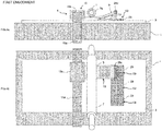
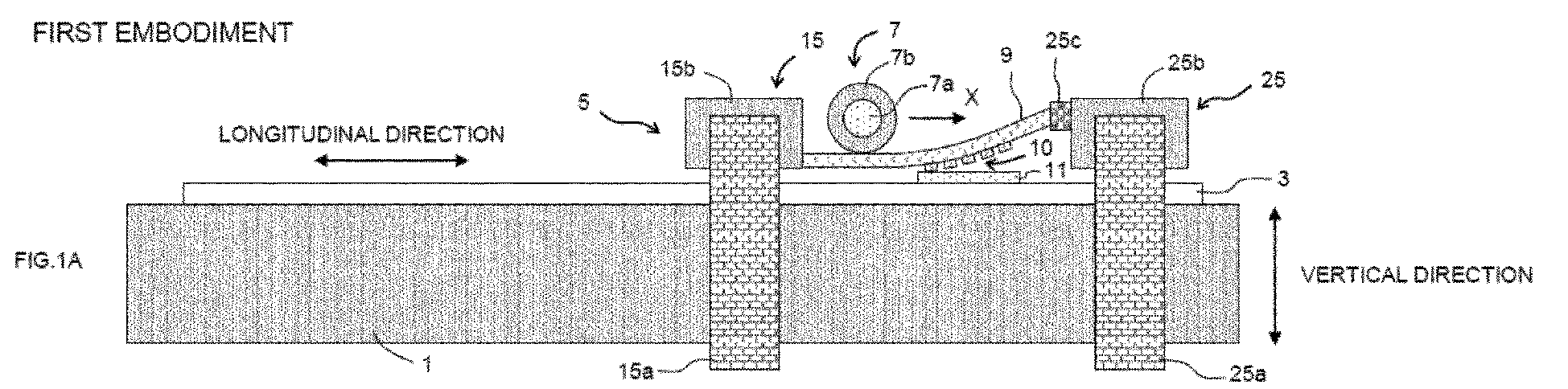
Figs. 1A and 1B illustrate a configuration of a step-and-repeat imprinting apparatus in a first embodiment of the present invention, whereFig. 1A is a front view andFig. 1B is a plan view. -
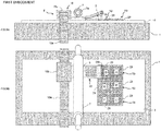
Figs. 2A and 2B are illustrative diagrams of a step-and-repeat imprinting method by the imprinting apparatus inFigs. 1A and 1B , whereFig. 2A is a front view andFig. 2B is a plan view. -
Figs. 3A and 3B are illustrative diagrams of the step-and-repeat imprinting method by the imprinting apparatus inFigs. 1A and 1B , whereFig. 3A is a front view andFig. 3B is a plan view. -
Figs. 4A and 4B are illustrative diagrams of the step-and-repeat imprinting method by the imprinting apparatus inFigs. 1A and 1B , whereFig. 4A is a front view andFig. 4B is a plan view. -
Figs. 5A and 5B are illustrative diagrams of the step-and-repeat imprinting method by the imprinting apparatus inFigs. 1A and 1B , whereFig. 5A is a front view andFig. 5B is a plan view. -
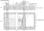
Figs. 6A and 6B illustrate a configuration of a step-and-repeat imprinting apparatus in a second embodiment of the present invention, whereFig. 6A is a front view andFig. 6B is a plan view. -
Figs. 7A and 7B are illustrative diagrams of a step-and-repeat imprinting method by the imprinting apparatus inFigs. 6A and 6B , whereFig. 7A is a front view andFig. 7B is a plan view. -
Figs. 8A and 8B are illustrative diagrams of the step-and-repeat imprinting method by the imprinting apparatus inFigs. 6A and 6B , whereFig. 8A is a front view andFig. 8B is a plan view. -
Figs. 9A and 9B are illustrative diagrams of the step-and-repeat imprinting method by the imprinting apparatus inFigs. 6A and 6B , whereFig. 9A is a front view andFig. 9B is a plan view. -
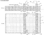
Figs. 10A and 10B illustrate a configuration of a step-and-repeat imprinting apparatus in a third embodiment of the present invention, whereFig. 10A is a front view andFig. 10B is a plan view. -
Figs. 11A and 11B are illustrative diagrams of a positioning method by the imprinting apparatus inFigs. 10A and 10B , whereFig. 11A is a front view andFig. 11B is a plan view. -
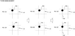
Figs. 12A toh 12F illustrate images taken byimaging units Figs. 11A and 11B , whereFig. 12A and Fig. 12B illustrate the state before correction,Fig. 12C and Fig. 12D illustrate the state after tilt correction, andFig. 12E and Fig. 12F illustrate the state after longitudinal position correction. - Preferred embodiments of the present invention are specifically described below with reference to the drawings.
- As illustrated in
Figs. 1A and 1B , a step-and-repeat imprinting apparatus in the first embodiment of the present invention includes astage 1 to place astage base 3, apositioning mechanism 5 configured to be relatively movable to thestage 1 and to keep aflexible base 9 to face thestage base 3, and apressurizing mechanism 7 to press, while deflecting theflexible base 9, theflexible base 9 toward thestage base 3. - In the present embodiment, a partial region of the
flexible base 9 is provided with a convex andconcave pattern 10, and thestage base 3 is formed with a transferredresin layer 11 to have the convex andconcave pattern 10 transferred thereto. Then, thepressurizing mechanism 7 is configured to press, while deflecting, theflexible base 9 toward thestage base 3, thereby transferring the convex andconcave pattern 10 to the transferredresin layer 11. Accordingly, theflexible base 9 having the convex andconcave pattern 10 functions as an imprinting mold. - More specifically, the
positioning mechanism 5 includes a rearend holding unit 15 to keep a rear end side of theflexible base 9 and a frontend holding unit 25 to keep a front end side of theflexible base 9. The rearend holding unit 15 includes alongitudinal driving unit 15a configured to be movable in a longitudinal direction of thestage 1 and atransverse driving unit 15b supported by thelongitudinal driving unit 15a and configured to be movable in a transverse direction of thestage 1. The frontend holding unit 25 includes alongitudinal driving unit 25a configured to be movable in the longitudinal direction of thestage 1, atransverse driving unit 25b supported by thelongitudinal driving unit 25a and configured to be movable in the transverse direction of thestage 1, and avertical driving unit 25c supported by thetransverse driving unit 25b and configured to be movable in a vertical direction of thestage 1. The rear end side of theflexible base 9 is two dimensionally movable over thestage 1 by being supported by thetransverse driving unit 15b. The front end side of theflexible base 9 is three dimensionally movable over thestage 1 by being supported by thevertical driving unit 25c. The configuration of thepositioning mechanism 5 is not limited to those described here and various configurations are applicable. For example, the rearend holding unit 15 may be provided with a vertical driving unit to support the rear end side of theflexible base 9 by the vertical driving unit. In this case, the rear end side of theflexible base 9 also becomes three dimensionally movable over thestage 1 and thus the gap between theflexible base 9 and thestage base 3 is more readily adjusted. For step-and-repeat only in the transverse direction, thelongitudinal driving units - The
pressurizing mechanism 7 is configured with acolumn roller 7b rotatable on therotation shaft 7a. Therotation shaft 7a is supported by bearings of a support mechanism, not shown, movable in the longitudinal direction of thestage 1. Such a configuration causes theroller 7b to move on theflexible base 9 while rotating on theflexible base 9, thereby enabling pressing of theflexible base 9 against thestage base 3. Thepressurizing mechanism 7 only has to press, while deflecting, theflexible base 9 toward thestage base 3, and thus theroller 7b does not have to rotate. Thepressurizing mechanism 7 may be configured to move a blade in a plate shape instead of theroller 7b. Moreover, thepressurizing mechanism 7 may be configured to press, while deflecting, theflexible base 9 without moving. Further, if thepressurizing mechanism 7 presses, while deflecting, theflexible base 9 using a gas, such as air, toward thestage base 3, it does not have to contact theflexible base 9 with thepressurizing mechanism 7. - Here, using the imprinting apparatus in the present embodiment, a method of step-and-repeat imprinting is described.
- First, as illustrated in
Figs. 1A and 1B , thestage base 3 is placed on thestage 1 and the transferredresin layer 11 is formed on thestage base 3. Theflexible base 9 having the convex andconcave pattern 10 is attached to thepositioning mechanism 5. - The
stage base 3 may or may not be flexible and may or may not be transparent. To thestage base 3, various bases such as resin bases, quartz bases, silicone bases, and silicon bases are applicable. - The transferred
resin layer 11 is formed by applying a photocurable resin composition on thestage base 3. Such a photocurable resin composition contains a monomer and a photoinitiator and has properties to be cured by irradiation with an activation energy line. "The activation energy line" is the generic name for energy lines capable of curing a photocurable resin composition, such as UV light, visible light, and electron beams. The transferredresin layer 11 is generally a transparent resin layer and generally has a thickness from 50 nm to 1 mm and preferably from 500 nm to 500 µm. A thickness in this range facilitates imprinting. In the present embodiment, every time imprinting is performed, a transferredresin layer 11 is formed in a region for the next imprinting. That is, imprinting and formation of the transferredresin layer 11 is alternately performed. The method is not limited to this embodiment, and the transferredresin layer 11 may be formed in the entire region for imprinting at first or the transferredresin layer 11 may be formed at once in a region equivalent to a plurality of imprinting procedures to reduce the number of the transferredresin layer 11 formation steps. - The
flexible base 9 is a base has flexibility. The transferredresin layer 11 is generally irradiated with activation energy lines 27 (seeFigs. 2A and 2B ) through theflexible base 9, and thus theflexible base 9 is preferably transparent. Theflexible base 9 is, for example, a resin base. Examples of an applicable resin include polyethylene terephthalate, polycarbonate, polyester, polyolefin, polyimide, polysulfone, polyether sulfone, cyclic polyolefin, polyethylene naphthalate, and the like. - The convex and
concave pattern 10 is formed on a resin layer formed by applying a thermoplastic resin, a thermosetting resin, or a photocurable resin on theflexible base 9. The resin to be applied is preferably a photocurable resin. Specific examples include an acrylic resin, a styrene resin, an olefin resin, a polycarbonate resin, a polyester resin, an epoxy resin, a silicone resin, and the like. The resin may contain a peeling component, such as a fluorine compound, a long chain alkyl compound, and wax. The convex andconcave pattern 10 is not particularly limited, and preferably has intervals from 10 nm to 2 mm, a depth from 10 nm to 500 µm, and a transfer surface from 1.0 to 1.0 × 106 mm2, and more preferably intervals from 20 nm to 20 µm, a depth from 50 nm to 1 µm, and a transfer surface from 1.0 to 0.25 × 106 mm2. Such settings enable sufficient transfer of the convex andconcave pattern 10 to a transfer body. Examples of the surface shape include moth eye patterns, lines, columns, monoliths, cones, polygonal pyramids, and microlens arrays. - Next, the
positioning mechanism 5 and thepressurizing mechanism 7 are moved to the positions illustrated inFigs. 1A and 1B . Thepressurizing mechanism 7 is located in a position close to the rearend holding unit 15, and thevertical driving unit 25c of the frontend holding unit 25 is in a relatively high position. In this state, theflexible base 9 is deflected. Thepressurizing mechanism 7 is not positioned above the transferredresin layer 11 and the convex andconcave pattern 10 is not transferred to the transferredresin layer 11. - Then, from the state in
Figs. 1A and 1B , thepressurizing mechanism 7 is moved in a direction indicated by an arrow X inFigs. 1A and 1B and thevertical driving unit 25c is lowered to be brought into the state illustrated inFigs. 2A and 2B . At this point, an end of the convex andconcave pattern 10 makes contact with the transferredresin layer 11 at first. With the lowering of thevertical driving unit 25c and the movement of thepressurizing mechanism 7, the convex andconcave pattern 10 is pressed against the transferredresin layer 11 while a contact area of the convex andconcave pattern 10 and the transferredresin layer 11 gradually increases, and finally, the entire convex andconcave pattern 10 is transferred to the transferredresin layer 11. According to such a transfer method, air is well removed and high pressure press does not have to be carried out. In addition, the flatness and parallelism of the upper and lower surfaces of thestage 1 do not affect much. - Then, as illustrated in
Figs. 2A and 2B , while the convex andconcave pattern 10 is pressed against the transferredresin layer 11, the transferredresin layer 11 is irradiated with theactivation energy lines 27 through theflexible base 9 to cure the transferredresin layer 11. As illustrated inFigs. 3B ,4A and 4B , a curedresin layer 29 having areverse pattern 10r formed by reversing the convex andconcave pattern 10 is thus formed. If thepressurizing mechanism 7 is transparent, asFigs. 2A and 2B , irradiation with theactivation energy lines 27 can be carried out while locating thepressurizing mechanism 7 over the transferredresin layer 10. Meanwhile, as illustrated inFigs. 1A and 1B , the irradiation with theactivation energy lines 27 may be carried out by putting back thepressurizing mechanism 7 in a position close to the rearend holding unit 15. - Then, if the
pressurizing mechanism 7 is over the transferredresin layer 11, thepressurizing mechanism 7 is put back in a position close to the rearend holding unit 15 to raise thevertical driving unit 25c, thereby peeling the convex andconcave pattern 10 from the curedresin layer 29. At this point, while theflexible base 9 is deflected, the peeling gradually proceeds from an end of the convex andconcave pattern 10. The force for peeling is thus relatively small and a risk of damaging the convex andconcave pattern 10 and thereverse pattern 10r is reduced. - Then, as illustrated in
Figs. 3A and 3B , thetransverse driving units stage 1 to form a curedresin layer 29 having thereverse pattern 10r in the same manner. - After completion of step-and-repeat in the transverse direction, as illustrated in
Figs. 4A and 4B throughFigs. 5A and 5B , thelongitudinal driving units stage 1 to form a curedresin layer 29 having thereverse pattern 10r in the same manner. For the convenience of the illustration,Figs. 4A and 4B throughFigs. 5A and 5B do not illustrate thelongitudinal driving unit 25a and thetransverse driving unit 25b. - By repeating the above procedure, a microstructure formed with the
reverse pattern 10r of a desired area on thestage base 3 is formed. Such a microstructure is applicable to imprinting molds, stampers for microcontact printing, optical sheets (antireflective sheets, hologram sheets, lens sheets, and polarization separation sheets), water repellent sheets, hydrophilic sheets, cell culture sheets, and the like. - The order of step-and-repeat is not particularly limited and examples of the order include the order of A, B, C, D, E, and F in
Figs. 5A and 5B , the order of A, B, C, F, E, and D, the order of A, C, B, D, F, and E, and the like. - In the first embodiment, the
flexible base 9 is provided with the convex andconcave pattern 10, and thestage base 3 is provided with the transferredresin layer 11. In the present embodiment, as illustrated inFigs. 6A and 6B , theflexible base 9 is provided with the transferredresin layer 11 and thestage base 3 is provided with the convex andconcave pattern 10 for step-and-repeat imprinting while theflexible base 9 is moved. Accordingly, thestage base 3 having the convex andconcave pattern 10 functions as an imprinting mold. - The imprinting apparatus in the present embodiment has the same basic configuration as that in the first embodiment, and the descriptions in common are omitted. In the present embodiment, a micropattern in a large area is formed in the
flexible base 9 by step-and-repeat imprinting, so that theflexible base 9 has to be larger than that in the first embodiment. In proportion to the increase in size of theflexible base 9, thetransverse driving unit 15b and thevertical driving unit 25c, keeping thebase 9, are made larger. As illustrated inFigs. 8A and 8B , thevertical driving unit 25c has a range of motion greater than that in the first embodiment to enable deflection of theflexible base 9 even when the position of the transferredresin layer 11 on theflexible base 9 is relatively apart from thevertical driving unit 25c. - Here, a method of step-and-repeat imprinting using the imprinting apparatus in the present embodiment is described.
- First, as illustrated in
Figs. 6A and 6B , thestage base 3 having the convex andconcave pattern 10 is placed on thestage 1. Theflexible base 9 is attached to thepositioning mechanism 5, and the transferredresin layer 11 is formed on theflexible base 9. - Next, the
positioning mechanism 5 and thepressurizing mechanism 7 are moved in a position illustrated inFigs. 6A and 6B . Thepressurizing mechanism 7 is located in a position closer to the rearend holding unit 15 than right above the transferredresin layer 11, and thevertical driving unit 25c of the frontend holding unit 25 is in a relatively high position. In this state, theflexible base 9 is deflected. Thepressurizing mechanism 7 is not positioned above the transferredresin layer 11 and the convex andconcave pattern 10 is not transferred to the transferredresin layer 11. - Then, from the state in
Figs. 6A and 6B , thepressurizing mechanism 7 is moved in a direction indicated by an arrow X inFigs. 6A and 6B and thevertical driving unit 25c is lowered to be brought into the state illustrated inFigs. 7A and 7B . At this point, an end of the convex andconcave pattern 10 makes contact with the transferredresin layer 11 at first. With the lowering of thevertical driving unit 25c and the movement of thepressurizing mechanism 7, the convex andconcave pattern 10 is pressed against the transferredresin layer 11 while a contact area of the convex andconcave pattern 10 and the transferredresin layer 11 gradually increases, and finally, the entire convex andconcave pattern 10 is transferred to the transferredresin layer 11. According to such a transfer method, air is well removed and high pressure press does not have to be carried out. In addition, the flatness and parallelism of the upper and lower surfaces of thestage 1 do not affect much. - Then, as illustrated in
Figs. 7A and 7B , while the convex andconcave pattern 10 is pressed against the transferredresin layer 11, the transferredresin layer 11 is irradiated with theactivation energy lines 27 through theflexible base 9 to cure the transferredresin layer 11. As illustrated inFigs. 8B ,9A and 9B , the curedresin layer 29 having thereverse pattern 10r formed by reversing the convex andconcave pattern 10 is formed. - Then, if the
pressurizing mechanism 7 is over the transferredresin layer 11, thepressurizing mechanism 7 is put back in a position close to the rearend holding unit 15 to raise thevertical driving unit 25c, thereby peeling the convex andconcave pattern 10 from the curedresin layer 29. At this point, while theflexible base 9 is deflected, the peeling gradually proceeds from an end of the convex andconcave pattern 10. The force for peeling is thus relatively small and a risk of damaging the convex andconcave pattern 10 and thereverse pattern 10r is reduced. - Then, as illustrated in
Figs. 8A and 8B , thetransverse driving units stage 1 to form a curedresin layer 29 having thereverse pattern 10r in the same manner. - After completion of step-and-repeat in the transverse direction, as illustrated in
Figs. 9A and 9B , thelongitudinal driving units stage 1 to form a curedresin layer 29 having thereverse pattern 10r in the same manner. By repeating the above procedure, a microstructure formed with thereverse pattern 10r of a desired area on theflexible base 9 is formed. - In the first and second embodiments, the position accuracy for movement of each driving unit of the rear
end holding unit 15 and the frontend holding unit 25 is dependent on the accuracy of a driving mechanism, such as screw feeding, whereas there is a problem that driving mechanisms with high accuracy are very expensive. The present embodiment is characterized by enabling high accuracy positioning relatively inexpensively. The present embodiment is applicable to the first and second embodiments and the descriptions in common are not repeated. Further,Figs. 10A and 10B throughFigs. 11A and 11B illustrate only the areas necessary for description of the present embodiment. - In the present embodiment, a
precision scale 41 is placed on thestage 1. On theprecision scale 41,multiple squares 43 are drawn with high accuracy of dimension. Thestage base 3 in the first and second embodiments is placed on theprecision scale 41. A transparent base is used as thestage base 3, and thesquares 43 are observable through thestage base 3. Thesquares 43 are immobile during the positioning of thepositioning mechanism 5 and function as the "fixing mark" in the scope of claims. - The
longitudinal driving unit 15a of the frontend holding unit 15 has approximately both ends provided withtransparent plates 31b having marks marks positioning mechanism 5 and function as the "movement mark" in the scope of claims. - The
stage 1 is provided with animaging mechanism 35. Theimaging mechanism 35 includes alongitudinal driving unit 35a. Thelongitudinal driving unit 35a includesimaging units units imaging units - Then, a method of positioning with high accuracy using the
squares 43 and themarks longitudinal driving unit 15a is described in detail while the same method is applicable to other driving units. - First, the
longitudinal driving unit 15a is moved to a desired position in the longitudinal direction of thestage 1.Figs. 10A and 10B illustrate an example of a state after movement. - Next, the
longitudinal driving unit 35a is moved to position theimaging units marks marks squares 43 are imaged from right above themarks Figs. 12A and 12B illustrate an example of the images thus obtained. In this example, themark 33a is positioned on the left from themark 33b and thelongitudinal driving unit 15a is slightly tilted to the left. - Then, as illustrated in
Figs. 12C and 12D , thelongitudinal driving unit 15a is rotated clockwise until the left and right positions of themarks - Then, as illustrated in
Figs. 12E and 12F , thelongitudinal driving unit 15a is moved to position themarks vertical lines 43a of thesquares 43 to complete positioning of thelongitudinal driving unit 15a. According to such a method, even if thelongitudinal driving unit 15a has the driving mechanism with low accuracy, use of theprecision scale 41 with high accuracy enables positioning of thelongitudinal driving unit 15a with high accuracy. In the present embodiment, the twomarks longitudinal driving unit 15a as well, whereas one mark may be used for positioning of thelongitudinal driving unit 15a to omit the tilt correction. In addition, thetransverse driving unit 15b may be provided with similar marks to allow positioning of thetransverse driving unit 15b with high accuracy. The fixing mark and the movement mark are not limited in their shapes as long as they allow positioning of thepositioning mechanism 5. - 1: Stage, 3: Stage Base, 5: A Positioning Mechanism, 7: Pressurizing Mechanism, 9: Flexible Base, 10: Convex and Concave Pattern, 10r: Reverse Pattern, 11: Transferred Resin Layer, 15: Rear End Holding Unit, 25: Front End Holding Unit, 29: Cured Resin Layer, 35: Imaging Mechanism
Claims (10)
- A step-and-repeat imprinting apparatus, comprising:a stage to place a stage base;a positioning mechanism configured to be relatively movable to the stage and to keep a flexible base to face the stage base; anda pressurizing mechanism to press, while deflecting the flexible base, the flexible base toward the stage base, whereinone of the stage base and the flexible base has a convex and concave pattern, and another of the stage base and the flexible base includes a transferred resin layer to have the convex and concave pattern transferred thereto, andthe apparatus is so configured that the pressurizing mechanism presses, while deflecting, the flexible base toward the stage base, thereby transferring the convex and concave pattern to the transferred resin layer.
- The apparatus of Claim 1, wherein the pressurizing mechanism is configured to be movable on the flexible base.
- The apparatus of Claim 2, wherein the positioning mechanism is configured to be movable approximately vertically to a direction of movement of the pressurizing mechanism.
- The apparatus of Claim 2 or 3, wherein the positioning mechanism configured to be movable in a direction approximately identical to a direction of movement of the pressurizing mechanism.
- The apparatus of any one of Claims 1 to 4, wherein the positioning mechanism performs positioning using a fixing mark provided on the stage and a movement mark provided in the positioning mechanism.
- The apparatus of Claim 5, wherein the fixing mark is multiple squares provided on the stage.
- A step-and-repeat imprinting method, comprising:transferring, while facing a stage base placed on a stage to a flexible base kept relatively movable to the stage, a convex and concave pattern provided in one of the stage base and the flexible base to a transferred resin layer provided in another of the stage base and the flexible base by pressing the flexible base toward the stage base while deflecting the flexible base; andrepeating to perform the transferring step by moving the flexible base.
- The method of Claim 7, wherein the flexible base is pressed toward the stage base by moving a pressurizing mechanism on the flexible base.
- The method of Claim 8, wherein the repeating includes moving the flexible base approximately vertically to a direction of movement of the pressurizing mechanism, and performing the transferring.
- The method of Claim 8 or 9, wherein the repeating includes moving the flexible base in a direction approximately identical to a direction of movement of the pressurizing mechanism, and performing the transferring.
Applications Claiming Priority (2)
| Application Number | Priority Date | Filing Date | Title |
|---|---|---|---|
| JP2014147211 | 2014-07-17 | ||
| PCT/JP2015/070365 WO2016010105A1 (en) | 2014-07-17 | 2015-07-16 | Step-and-repeat-type imprinting device and method |
Publications (2)
| Publication Number | Publication Date |
|---|---|
| EP3171391A1 true EP3171391A1 (en) | 2017-05-24 |
| EP3171391A4 EP3171391A4 (en) | 2017-07-05 |
Family
ID=55078591
Family Applications (1)
| Application Number | Title | Priority Date | Filing Date |
|---|---|---|---|
| EP15822179.6A Withdrawn EP3171391A4 (en) | 2014-07-17 | 2015-07-16 | Step-and-repeat-type imprinting device and method |
Country Status (7)
| Country | Link |
|---|---|
| US (1) | US20170205708A1 (en) |
| EP (1) | EP3171391A4 (en) |
| JP (1) | JPWO2016010105A1 (en) |
| KR (1) | KR20170031710A (en) |
| CN (1) | CN106663603A (en) |
| TW (1) | TW201616553A (en) |
| WO (1) | WO2016010105A1 (en) |
Cited By (1)
| Publication number | Priority date | Publication date | Assignee | Title |
|---|---|---|---|---|
| US11472212B2 (en) | 2016-09-05 | 2022-10-18 | Ev Group E. Thallner Gmbh | Device and method for embossing micro- and/or nanostructures |
Families Citing this family (4)
| Publication number | Priority date | Publication date | Assignee | Title |
|---|---|---|---|---|
| CN108475621A (en) * | 2016-07-05 | 2018-08-31 | 松下知识产权经营株式会社 | Mold, imprinting device and imprinting method |
| JP6694101B1 (en) * | 2019-08-09 | 2020-05-13 | Aiメカテック株式会社 | Fine structure transfer apparatus and fine structure transfer method |
| CN113119642B (en) * | 2021-04-13 | 2022-07-01 | 北京黎马敦太平洋包装有限公司 | Impression workstation |
| JP7656356B1 (en) | 2023-09-29 | 2025-04-03 | Aiメカテック株式会社 | Microstructure transfer device and microstructure transfer method |
Family Cites Families (28)
| Publication number | Priority date | Publication date | Assignee | Title |
|---|---|---|---|---|
| JP2001058352A (en) * | 1999-06-14 | 2001-03-06 | Dainippon Printing Co Ltd | Contact transfer method and apparatus and transfer mold |
| JP2004165220A (en) * | 2002-11-08 | 2004-06-10 | Canon Inc | Projection exposure apparatus and method, and device manufacturing method |
| JP4478424B2 (en) * | 2003-09-29 | 2010-06-09 | キヤノン株式会社 | Microfabrication apparatus and device manufacturing method |
| JP4789039B2 (en) * | 2005-06-10 | 2011-10-05 | 独立行政法人産業技術総合研究所 | Nanoimprint equipment |
| US8011916B2 (en) | 2005-09-06 | 2011-09-06 | Canon Kabushiki Kaisha | Mold, imprint apparatus, and process for producing structure |
| JP4926881B2 (en) * | 2006-09-22 | 2012-05-09 | キヤノン株式会社 | Imprint apparatus and alignment method |
| US8231372B2 (en) * | 2006-09-27 | 2012-07-31 | Toray Industries, Inc. | Intermittent film forming system and intermittent film forming method |
| US20100052216A1 (en) * | 2008-08-29 | 2010-03-04 | Yong Hyup Kim | Nano imprint lithography using an elastic roller |
| KR101880582B1 (en) * | 2008-12-05 | 2018-07-20 | 리퀴디아 테크놀로지스 인코포레이티드 | Method for producing patterned materials |
| JP5232077B2 (en) * | 2009-06-02 | 2013-07-10 | 株式会社日立ハイテクノロジーズ | Microstructure transfer device |
| JP5454160B2 (en) * | 2010-01-18 | 2014-03-26 | 富士通株式会社 | Imprint apparatus and imprint method |
| KR101421910B1 (en) * | 2010-09-01 | 2014-07-22 | 도시바 기카이 가부시키가이샤 | Transferring system and transferring method |
| JP5709558B2 (en) * | 2011-02-01 | 2015-04-30 | キヤノン株式会社 | Inspection method, imprint apparatus, and article manufacturing method |
| JP5289492B2 (en) * | 2011-03-23 | 2013-09-11 | 株式会社東芝 | Imprint method and imprint apparatus |
| JP5355614B2 (en) * | 2011-04-19 | 2013-11-27 | パナソニック株式会社 | Sheet-like device manufacturing apparatus and sheet-like device manufacturing method |
| CN104334333B (en) * | 2012-05-24 | 2017-03-01 | 旭硝子株式会社 | The manufacture method of optical component, optical component, carry the optical component of protecting film and the manufacture method of optic panel |
| JP2014004827A (en) * | 2012-05-31 | 2014-01-16 | Fujikura Ltd | Pattern forming method and mold release device |
| US9808985B2 (en) * | 2012-06-21 | 2017-11-07 | Scivax Corporation | Roller pressing device, imprinting device, and roller pressing method |
| KR20150028960A (en) * | 2012-09-06 | 2015-03-17 | 에베 그룹 에. 탈너 게엠베하 | Structure stamp, device and method for embossing |
| JP5723337B2 (en) * | 2012-09-07 | 2015-05-27 | 株式会社東芝 | Pattern forming method and pattern forming apparatus |
| JP5944800B2 (en) * | 2012-09-11 | 2016-07-05 | 東芝機械株式会社 | Transfer device |
| CN102929100B (en) * | 2012-11-22 | 2014-11-19 | 南昌欧菲光纳米科技有限公司 | A device and method for aligning roll-to-roll UV forming |
| JP6364684B2 (en) * | 2012-12-06 | 2018-08-01 | Scivax株式会社 | Roller type pressure device, imprint device, roller type pressure method |
| JP6207997B2 (en) * | 2013-01-30 | 2017-10-04 | 株式会社Screenホールディングス | Pattern forming apparatus and pattern forming method |
| JP6032492B2 (en) * | 2013-05-24 | 2016-11-30 | パナソニックIpマネジメント株式会社 | Fine pattern forming method and fine pattern forming apparatus |
| KR102219703B1 (en) * | 2014-05-07 | 2021-02-24 | 삼성전자주식회사 | Patterning method using imprint and pattern structure fabricated by the method, and imprinting system |
| EP3032573B1 (en) * | 2014-06-03 | 2018-10-10 | Scivax Corporation | Roller-type pressurizing device, imprint device, and roller-type pressurizing method |
| TWI677765B (en) * | 2017-02-28 | 2019-11-21 | 日商東芝機械股份有限公司 | Transfer method,and transfer apparatus |
-
2015
- 2015-07-15 TW TW104122859A patent/TW201616553A/en unknown
- 2015-07-16 EP EP15822179.6A patent/EP3171391A4/en not_active Withdrawn
- 2015-07-16 US US15/326,725 patent/US20170205708A1/en not_active Abandoned
- 2015-07-16 CN CN201580038910.1A patent/CN106663603A/en active Pending
- 2015-07-16 WO PCT/JP2015/070365 patent/WO2016010105A1/en not_active Ceased
- 2015-07-16 KR KR1020177003121A patent/KR20170031710A/en not_active Ceased
- 2015-07-16 JP JP2016534484A patent/JPWO2016010105A1/en active Pending
Cited By (1)
| Publication number | Priority date | Publication date | Assignee | Title |
|---|---|---|---|---|
| US11472212B2 (en) | 2016-09-05 | 2022-10-18 | Ev Group E. Thallner Gmbh | Device and method for embossing micro- and/or nanostructures |
Also Published As
| Publication number | Publication date |
|---|---|
| JPWO2016010105A1 (en) | 2017-04-27 |
| WO2016010105A1 (en) | 2016-01-21 |
| US20170205708A1 (en) | 2017-07-20 |
| EP3171391A4 (en) | 2017-07-05 |
| KR20170031710A (en) | 2017-03-21 |
| CN106663603A (en) | 2017-05-10 |
| TW201616553A (en) | 2016-05-01 |
Similar Documents
| Publication | Publication Date | Title |
|---|---|---|
| CN111201121B (en) | Double sided embossing | |
| JP5276436B2 (en) | Pattern duplication with intermediate stamp | |
| JP5232077B2 (en) | Microstructure transfer device | |
| US20170205708A1 (en) | Step-and-repeat-type imprinting device and method | |
| US7670127B2 (en) | Apparatus for pattern replication with intermediate stamp | |
| US8025829B2 (en) | Die imprint by double side force-balanced press for step-and-repeat imprint lithography | |
| US8172968B2 (en) | Method and system for contacting of a flexible sheet and a substrate | |
| CN101547748B (en) | Method and apparatus for applying a sheet to a substrate | |
| JP5912996B2 (en) | Transfer device | |
| JP2008542081A5 (en) | ||
| JP5395769B2 (en) | Template chuck, imprint apparatus, and pattern forming method | |
| JP5469941B2 (en) | Transfer apparatus and transfer method | |
| NL2003380A (en) | Imprint lithography apparatus and method. | |
| CN101171142A (en) | Method and apparatus for transferring a pattern from a stamp to a substrate | |
| JP2010269580A (en) | Imprint apparatus and article manufacturing method | |
| JP7637816B2 (en) | Method and apparatus for removing stamp | |
| CN103149796A (en) | Nano imprint lithography apparatuses and methods | |
| JP6391709B2 (en) | Method and apparatus for embossing nanostructures | |
| JP5328495B2 (en) | Imprint apparatus and article manufacturing method | |
| JP2013105755A (en) | Alignment method and method for forming recessed and projecting pattern | |
| US12292682B2 (en) | Method and device for producing micro- and/or nanostructures | |
| TW201720625A (en) | Manufacturing method of fine structure | |
| US20080258036A1 (en) | System for dimensional stability of elastomeric microdevices |
Legal Events
| Date | Code | Title | Description |
|---|---|---|---|
| STAA | Information on the status of an ep patent application or granted ep patent |
Free format text: STATUS: THE INTERNATIONAL PUBLICATION HAS BEEN MADE |
|
| PUAI | Public reference made under article 153(3) epc to a published international application that has entered the european phase |
Free format text: ORIGINAL CODE: 0009012 |
|
| STAA | Information on the status of an ep patent application or granted ep patent |
Free format text: STATUS: REQUEST FOR EXAMINATION WAS MADE |
|
| 17P | Request for examination filed |
Effective date: 20170215 |
|
| AK | Designated contracting states |
Kind code of ref document: A1 Designated state(s): AL AT BE BG CH CY CZ DE DK EE ES FI FR GB GR HR HU IE IS IT LI LT LU LV MC MK MT NL NO PL PT RO RS SE SI SK SM TR |
|
| AX | Request for extension of the european patent |
Extension state: BA ME |
|
| A4 | Supplementary search report drawn up and despatched |
Effective date: 20170601 |
|
| RIC1 | Information provided on ipc code assigned before grant |
Ipc: H01L 21/027 20060101AFI20170526BHEP Ipc: B29C 59/02 20060101ALI20170526BHEP |
|
| DAV | Request for validation of the european patent (deleted) | ||
| DAX | Request for extension of the european patent (deleted) | ||
| STAA | Information on the status of an ep patent application or granted ep patent |
Free format text: STATUS: THE APPLICATION HAS BEEN WITHDRAWN |
|
| 18W | Application withdrawn |
Effective date: 20190429 |