EP3171210A1 - Lens-driving apparatus - Google Patents
Lens-driving apparatus Download PDFInfo
- Publication number
- EP3171210A1 EP3171210A1 EP15822027.7A EP15822027A EP3171210A1 EP 3171210 A1 EP3171210 A1 EP 3171210A1 EP 15822027 A EP15822027 A EP 15822027A EP 3171210 A1 EP3171210 A1 EP 3171210A1
- Authority
- EP
- European Patent Office
- Prior art keywords
- lens
- end part
- drive signal
- holding section
- section
- Prior art date
- Legal status (The legal status is an assumption and is not a legal conclusion. Google has not performed a legal analysis and makes no representation as to the accuracy of the status listed.)
- Withdrawn
Links
- 230000007274 generation of a signal involved in cell-cell signaling Effects 0.000 claims description 11
- 230000003287 optical effect Effects 0.000 claims description 6
- XEEYBQQBJWHFJM-UHFFFAOYSA-N Iron Chemical compound [Fe] XEEYBQQBJWHFJM-UHFFFAOYSA-N 0.000 abstract description 94
- 229910052742 iron Inorganic materials 0.000 abstract description 47
- 238000010586 diagram Methods 0.000 description 10
- 230000000737 periodic effect Effects 0.000 description 8
- 238000003780 insertion Methods 0.000 description 4
- 230000037431 insertion Effects 0.000 description 4
- 238000000034 method Methods 0.000 description 4
- 238000003745 diagnosis Methods 0.000 description 2
- 238000012986 modification Methods 0.000 description 1
- 230000004048 modification Effects 0.000 description 1
- 229910001285 shape-memory alloy Inorganic materials 0.000 description 1
Images


Classifications
-
- G—PHYSICS
- G02—OPTICS
- G02B—OPTICAL ELEMENTS, SYSTEMS OR APPARATUS
- G02B7/00—Mountings, adjusting means, or light-tight connections, for optical elements
- G02B7/02—Mountings, adjusting means, or light-tight connections, for optical elements for lenses
- G02B7/04—Mountings, adjusting means, or light-tight connections, for optical elements for lenses with mechanism for focusing or varying magnification
- G02B7/09—Mountings, adjusting means, or light-tight connections, for optical elements for lenses with mechanism for focusing or varying magnification adapted for automatic focusing or varying magnification
-
- A—HUMAN NECESSITIES
- A61—MEDICAL OR VETERINARY SCIENCE; HYGIENE
- A61B—DIAGNOSIS; SURGERY; IDENTIFICATION
- A61B1/00—Instruments for performing medical examinations of the interior of cavities or tubes of the body by visual or photographical inspection, e.g. endoscopes; Illuminating arrangements therefor
- A61B1/00163—Optical arrangements
- A61B1/00188—Optical arrangements with focusing or zooming features
-
- A—HUMAN NECESSITIES
- A61—MEDICAL OR VETERINARY SCIENCE; HYGIENE
- A61B—DIAGNOSIS; SURGERY; IDENTIFICATION
- A61B1/00—Instruments for performing medical examinations of the interior of cavities or tubes of the body by visual or photographical inspection, e.g. endoscopes; Illuminating arrangements therefor
-
- G—PHYSICS
- G02—OPTICS
- G02B—OPTICAL ELEMENTS, SYSTEMS OR APPARATUS
- G02B23/00—Telescopes, e.g. binoculars; Periscopes; Instruments for viewing the inside of hollow bodies; Viewfinders; Optical aiming or sighting devices
- G02B23/24—Instruments or systems for viewing the inside of hollow bodies, e.g. fibrescopes
- G02B23/2407—Optical details
- G02B23/2423—Optical details of the distal end
- G02B23/243—Objectives for endoscopes
- G02B23/2438—Zoom objectives
-
- G—PHYSICS
- G02—OPTICS
- G02B—OPTICAL ELEMENTS, SYSTEMS OR APPARATUS
- G02B23/00—Telescopes, e.g. binoculars; Periscopes; Instruments for viewing the inside of hollow bodies; Viewfinders; Optical aiming or sighting devices
- G02B23/24—Instruments or systems for viewing the inside of hollow bodies, e.g. fibrescopes
- G02B23/2476—Non-optical details, e.g. housings, mountings, supports
-
- G—PHYSICS
- G02—OPTICS
- G02B—OPTICAL ELEMENTS, SYSTEMS OR APPARATUS
- G02B7/00—Mountings, adjusting means, or light-tight connections, for optical elements
- G02B7/02—Mountings, adjusting means, or light-tight connections, for optical elements for lenses
- G02B7/04—Mountings, adjusting means, or light-tight connections, for optical elements for lenses with mechanism for focusing or varying magnification
-
- G—PHYSICS
- G02—OPTICS
- G02B—OPTICAL ELEMENTS, SYSTEMS OR APPARATUS
- G02B7/00—Mountings, adjusting means, or light-tight connections, for optical elements
- G02B7/02—Mountings, adjusting means, or light-tight connections, for optical elements for lenses
- G02B7/04—Mountings, adjusting means, or light-tight connections, for optical elements for lenses with mechanism for focusing or varying magnification
- G02B7/08—Mountings, adjusting means, or light-tight connections, for optical elements for lenses with mechanism for focusing or varying magnification adapted to co-operate with a remote control mechanism
-
- G—PHYSICS
- G02—OPTICS
- G02B—OPTICAL ELEMENTS, SYSTEMS OR APPARATUS
- G02B7/00—Mountings, adjusting means, or light-tight connections, for optical elements
- G02B7/02—Mountings, adjusting means, or light-tight connections, for optical elements for lenses
- G02B7/04—Mountings, adjusting means, or light-tight connections, for optical elements for lenses with mechanism for focusing or varying magnification
- G02B7/10—Mountings, adjusting means, or light-tight connections, for optical elements for lenses with mechanism for focusing or varying magnification by relative axial movement of several lenses, e.g. of varifocal objective lens
- G02B7/102—Mountings, adjusting means, or light-tight connections, for optical elements for lenses with mechanism for focusing or varying magnification by relative axial movement of several lenses, e.g. of varifocal objective lens controlled by a microcomputer
Definitions
- the present invention relates to a lens driving apparatus, and in particular to a lens driving apparatus that periodically generates a drive signal causing a lens holding section to move.
- An endoscope system that includes an endoscope, processor, and the like has been conventionally widely used in a medical field, an industrial field, and other fields.
- the endoscope picks up an image of an object inside a subject, and the processor generates an observation image of the object picked up by the endoscope.
- An endoscope that includes, for example, an electromagnetic actuator at a distal end, drives a focus lens and a zoom lens with use of the electromagnetic actuator, and accordingly performs focus adjustment and zoom observation, has been used.
- Japanese Patent Application Laid-Open Publication No. 2009-204714 discloses an image pickup apparatus that causes a lens holder housing a lens, to move between a normal position and a macro position, thereby being capable of performing focus adjustment.
- the image pickup apparatus when the lens holder is displaced from the normal position to the macro position, the image pickup apparatus first applies a long pulse signal requiring a long application time period, to a coil once, and subsequently applies a short pulse signal requiring a short application time period, to the coil multiple times, thereby causing the lens holder to move toward the macro position. Thereafter, when the lens holder has moved to the macro position, the image pickup apparatus stops application of the pulse.
- the electromagnetic actuator when large impact is applied to the electromagnetic actuator while the pulse signal is not applied, the electromagnetic actuator may move unintentionally.
- the above-described image pickup apparatus may not maintain the intended focus state and the intended observation field, and may be put into unintended endoscope observation state.
- an object of the present invention is to provide a lens driving apparatus that allows for stable endoscope observation even if any impact is applied to an actuator.
- a lens driving apparatus includes: a first lens; a first lens holding section that holds the first lens to be movable between an end part and another end part; a first magnet that is provided on the end part and the other end part, and attracts and holds the first lens holding section when the first lens holding section comes into contact with one of the end part and the other end part; a first drive signal generation section that generates a drive signal bringing the first lens holding section into contact with one of the end part and the other end part; an instruction section that instructs the first drive signal generation section to move the first lens holding section to bring the first lens holding section into contact with the end part or move the first lens holding section to bring the first lens holding section into contact with the other end part; and a drive signal control section that generates a drive signal causing the first lens holding section to move in a direction instructed by the instruction section and supplies the drive signal to the first drive signal generation section, and controls the first drive signal generation section to periodically generate the drive signal causing the first lens holding section to move toward the instructed end part even
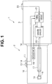
- Fig. 1 is a diagram illustrating a configuration of an endoscope apparatus configuring the lens driving apparatus according to the first embodiment.
- an endoscope apparatus 1 that is the lens driving apparatus includes an endoscope 2 and a driving unit 3 that is provided at a distal end of the endoscope 2 to drive an electromagnetic actuator 15 described later.
- the endoscope 2 includes: an elongated insertion portion 10 that is to be inserted into a subject; an operation section 11 for various kinds of operation of the endoscope 2, the operation section 11 being provided at a proximal end of the insertion portion 10; and a connector portion 12 provided at a proximal end of the operation section 11.
- the endoscope 2 is detachably connected to the driving unit 3 through the connector portion 12.
- the operation section 11 serving as an instruction section includes a Near button 13 to set a focus position at a near point and a Normal button 14 to set the focus position at a normal point.
- the endoscope 2 is mounted with the electromagnetic actuator 15 and a focus lens unit 16 that is driven by the electromagnetic actuator 15, at the distal end.
- a power supply cable 17 is connected to the electromagnetic actuator 15, and a drive current is supplied from the driving unit 3 to the electromagnetic actuator 15.
- the driving unit 3 includes: a timing generation circuit 21 that generates a drive pulse; a driver circuit 22 that generates the drive current based on the drive pulse provided from the timing generation circuit 21 and supplies the generated drive current to the electromagnetic actuator 15 through the power supply cable 17; and a setting section 23 to set various kinds of setting of the driving unit 3.
- the timing generation circuit 21 serving as a drive signal control section outputs the drive pulse to one of an A input terminal and a B input terminal of the driver circuit 22 according to an operation state of one of the Near button 13 and the Normal button 14 of the operation section 11.
- the timing generation circuit 21 may be configured of, for example, an FPGA or a microcomputer. Further, the timing generation circuit 21 does not have to be provided in the driving unit 3.
- the driver circuit 22 serving as a first drive signal generation section, is a circuit that causes the drive current to flow through the electromagnetic actuator 15 in a predetermined direction and a direction opposite to the predetermined direction, namely, in both directions.
- the driver circuit 22 is, for example, an H-bridge circuit that is configured of four switching devices (such as MOSFETs, bipolar transistors, or the like).
- the driver circuit 22 changes the direction of the drive current that is to flow through the electromagnetic actuator 15, based on whether the drive pulse provided from the timing generation circuit 21 is received by the A input terminal or the B input terminal.
- Fig. 2 is a cross-sectional diagram to explain the configurations of the electromagnetic actuator 15 and the focus lens unit 16.
- the electromagnetic actuator 15 includes: a cylindrical soft iron 31; a coil 32 wound around an outer periphery of the soft iron 31; a magnet 33 and a magnet 34 that are respectively provided on one end side (front side of the insertion portion 10) and the other end side (rear side of the insertion portion 10); and a contact part 35 and a contact part 36 with which the soft iron 31 comes into contact.
- the cylindrical soft iron 31 configures a lens holding section that so holds a focus lens 16a of the focus lens unit 16 as to be movable between the contact part 35 (one end part) and the contact part 36 (the other end part).
- the lens 16a serving as a first lens, is a focus lens that varies a focal distance of an objective optical system including the lens 16a, along with movement of the soft iron 31.
- the focus lens unit 16 includes one focus lens 16a, the number of the focus lens is not limited to one, and the focus lens unit 16 may include two or more focus lenses.
- the soft iron 31, serving as the lens holding section holds the two or more lenses.
- the magnet 33 and the magnet 34 configure a first magnet that attracts and holds the soft iron 31 when the soft iron 31 comes into contact with one of the contact part 35 and the contact part 36.
- Fig. 3 is a diagram to explain an example of the drive pulse supplied to the electromagnetic actuator 15 and a state of the lens 16a.
- an operation signal of the button is provided to the timing generation circuit 21.
- the timing generation circuit 21 When receiving the operation signal that indicates pressing of the Near button 13, the timing generation circuit 21 generates the drive pulse illustrated in Fig. 3 , and provides the generated drive pulse to the A input terminal of the driver circuit 22.
- the driver circuit 22 When receiving the drive pulse through the A input terminal, the driver circuit 22 applies the drive current to the electromagnetic actuator 15 in the predetermined direction through the power supply cable 17.
- the drive current flows through the electromagnetic actuator 15 in the predetermined direction, the soft iron 31 and the lens 16a accordingly move rightward in Fig. 2 , and then the right magnet 34 attracts and stops the soft iron 31.
- the pulse is repeatedly and periodically applied to the coil 32 even after the right magnet 34 attracts and stops the soft iron 31, for example, by the pulse at a time T0 in Fig. 3 .
- the timing generation circuit 21 generates the drive pulse that causes the soft iron 31 to move in the direction instructed by the operation section 11, and supplies the generated drive pulse to the driver circuit 22.
- the timing generation circuit 21 controls the driver circuit 22 to periodically generate the drive signal that causes the soft iron 31 to move in the direction instructed by the operation section 11 even after the soft iron 31 is attracted to the magnet 34.
- an operation signal of the button is provided to the timing generation circuit 21.
- the timing generation circuit 21 When receiving the operation signal that indicates pressing of the Normal button 14 for focusing, the timing generation circuit 21 generates the above-described periodic pulse illustrated in Fig. 3 , and provides the periodic pulse to the B input terminal of the driver circuit 22.
- the driver circuit 22 When receiving the drive pulse through the B input terminal, the driver circuit 22 applies the drive current to the electromagnetic actuator 15 in a direction opposite to the predetermined direction, through the power supply cable 17.
- the current flows through the electromagnetic actuator 15 in the direction opposite to the predetermined direction, the soft iron 31 and the lens 16a accordingly move leftward in Fig. 2 , and then the left magnet 33 attracts and stops the soft iron 31.
- the pulse is repeatedly and periodically applied to the coil 32 even after the left magnet 33 attracts and stops the soft iron 31, for example, by the pulse at the time T0 in Fig. 3 .
- Such periodic application of the pulse to the coil 32 draws back the lens 16a toward the contact part 36 by a next pulse, even if any impact is applied to the electromagnetic actuator 15 (or the predetermined position of the endoscope 2) while the soft iron 31 is in contact with the contact part 36, for example.
- the pulse is applied to the coil 32 at a time T2 when the pulse is not applied to the coil 32 and the soft iron 31 is separated from (unfixed to) the contact part 36, the pulse is applied to the coil 32 at a time T2, the soft iron 31 is accordingly drawn back toward the contact part 36, and the magnet 34 attracts (Near) and stops the soft iron 31.
- the repetition period of the pulse application is set to a short time (for example, about one second) that does not interfere with diagnosis even if the endoscope observation field is deviated for a moment. Setting the repetition period to a shorter time period suppresses deviation of the endoscope observation field.
- the repetition period may be desirably set to a time period that does not allow overheat caused by energization of the electromagnetic actuator 15, for example, about one second as mentioned above.
- the repetition period of the pulse application is not necessarily constant consistently, and the period may be varied, for example, depending on a pulse to be applied. Further, a user may set the repetition period of the pulse application with use of the setting section 23. Furthermore, the timing generation circuit 21 may vary the repetition period of the pulse application based on the endoscope ID 18 provided from the endoscope 2 that is connected to the driving unit 3.
- the focus lens unit 16 is driven with use of the electromagnetic actuator 15 in the present embodiment, the actuator is not limited to the electromagnetic actuator 15, and the focus lens unit 16 may be driven with use of, for example, a piezoelectric actuator or a shape-memory-alloy actuator.
- the endoscope apparatus 1 configuring the lens driving apparatus periodically applies the pulse to the electromagnetic actuator 15 even after the soft iron 31 is attracted to one of the magnet 33 and the magnet 34.
- the endoscope apparatus 1 even if external impact is applied to the electromagnetic actuator 15 (or the predetermined position of the endoscope 2) and the soft iron 31 is accordingly separated from the magnet 33 or 34 during the endoscope observation, the soft iron 31 is immediately attracted to the magnet 33 or 34. Therefore, the endoscope observation is not interfered.
- the lens driving apparatus of the present embodiment allows for stable endoscope observation even if any impact is applied to the actuator.
- Fig. 4 is a diagram illustrating a configuration of an endoscope apparatus configuring a lens driving apparatus according to a second embodiment. Note that components in Fig. 4 similar to the components in Fig. 1 are denoted by the same reference numerals, and description of such components is omitted.
- An endoscope apparatus 1a of the present embodiment is configured to perform zoom adjustment, in addition to the focus adjustment described in the first embodiment. As illustrated in Fig. 4 , the endoscope apparatus 1a includes an endoscope 2a and a driving unit 3a.
- the endoscope 2a further includes a Tele button 40 and a Wide button 41 for zooming in the operation section 11, as compared with the endoscope 2 of Fig. 1 .
- the endoscope 2a further includes, at a distal end, an electromagnetic actuator 42 and a zoom lens unit 43 that is driven by the electromagnetic actuator 42, as compared with the endoscope 2 of Fig. 1 .
- the electromagnetic actuator 42 is connected to a power supply cable 44, and a drive current is supplied from the driving unit 3a to the electromagnetic actuator 42.
- the driving unit 3a further includes a driver circuit 45, as compared with the driving unit 3 of Fig. 1 .
- the timing generation circuit 21 provides a drive pulse to one of a C input terminal and a D input terminal of the driver circuit 45 according to an operation state of one of the Tele button 40 and the Wide button 41 of the operation section 11.
- the driver circuit 45 is a circuit that causes the drive current to flow through the electromagnetic actuator 42 in a predetermined direction and a direction opposite to the predetermined direction, namely, in both directions, as with the driver circuit 22.
- Examples of the driver circuit 45 may include an H-bridge circuit.
- the driver circuit 45 changes the direction of the drive current that is to flow through the electromagnetic actuator 42, based on whether the drive pulse provided from the timing generation circuit 21 is received by the C input terminal or the D input terminal.
- Fig. 5 is a cross-sectional diagram to explain configurations of the electromagnetic actuator 42 and the zoom lens unit 43. Note that components in Fig. 5 similar to the components in Fig. 2 are denoted by the same reference numerals, and description of such components is omitted.
- the electromagnetic actuator 42 of the present embodiment has a configuration similar to the configuration of the electromagnetic actuator 15 of the first embodiment, and a zoom lens 43a of the zoom lens unit 43 is held by the soft iron 31.
- the cylindrical soft iron 31 configures a lens holding section that so holds the zoom lens 43a of the zoom lens unit 43 as to be movable between the contact part 35 (one end part) and the contact part 36 (the other end part).
- the lens 43a is a variable power lens that varies a magnification factor of an optical image, along with the movement of the soft iron 31. Note that, although the zoom lens unit 43 includes one zoom lens 43a, the number of the zoom lens is not limited to one, and the zoom lens unit 43 may include two or more lenses.
- a method of controlling the electromagnetic actuator 42 is now described.
- the method of controlling the electromagnetic actuator 42 is substantially similar to the method of controlling the electromagnetic actuator 15.
- an operation signal of the button is provided to the timing generation circuit 21.
- the timing generation circuit 21 When receiving the operation signal that indicates pressing of the Tele button 40, the timing generation circuit 21 generates the above-described periodic pulse illustrated in Fig. 3 , and provides the periodic pulse to the C input terminal of the driver circuit 45.
- the driver circuit 45 applies the drive current to the electromagnetic actuator 42 in the predetermined direction through the power supply cable 44.
- the current flows through the electromagnetic actuator 42 in the predetermined direction, the soft iron 31 and the lens 43a accordingly move rightward in Fig. 4 , and then the right magnet 34 attracts and stops the soft iron 31.
- the right magnet 34 attracts and stops the soft iron 31.
- the pulse is repeatedly and periodically applied to the coil 32 even after the right magnet 34 attracts and stops the soft iron 31, for example, by the pulse at a time T0 in Fig. 3 .
- the timing generation circuit 21 When receiving the operation signal that indicates pressing of the Normal button 41 for zooming, the timing generation circuit 21 generates the above-described periodic pulse illustrated in Fig. 3 , and provides the periodic pulse to the D input terminal of the driver circuit 45. When receiving the drive pulse through the D input terminal, the driver circuit 45 applies the drive current to the electromagnetic actuator 42 in the direction opposite to the predetermined direction, through the power supply cable 44.
- the current flows through the electromagnetic actuator 42 in the direction opposite to the predetermined direction, the soft iron 31 and the lens 43a accordingly move leftward in Fig. 4 , and then the left magnet 33 attracts and stops the soft iron 31.
- the pulse is repeatedly and periodically applied to the coil 32, even after the left magnet 33 attracts and stops the soft iron 31, for example, by the pulse at the time T0 in Fig. 3 .
- Such periodic application of the pulse to the coil 32 draws back the lens 43a toward the contact part 36 by a next pulse, for example, even if any impact is applied to the electromagnetic actuator 42 (or the predetermined position of the endoscope 2a) while the soft iron 31 is in contact with the contact part 36.
- the repetition period of the pulse application is set to a short time period (for example, about one second) that does not interfere with diagnosis even if the endoscope observation field is deviated for a moment, as with the first embodiment.
- the repetition period of the pulse application is not necessarily constant consistently, and the period may be varied, for example, depending on the pulse to be applied, as with the first embodiment. Further, the user may set the repetition period of the pulse application with use of the setting section 23. Furthermore, the timing generation circuit 21 may vary the repetition period of the pulse application based on the endoscope ID 18 provided from the endoscope 2a that is connected to the driving unit 3 a.
- the drive pulse to be applied to the electromagnetic actuator 42 is described with reference to Fig. 3 , namely, the drive pulse to be applied to the electromagnetic actuator 42 is described as the drive pulse same as the drive pulse to be applied to the electromagnetic actuator 15 in the first embodiment.
- the drive pulse to be applied to the electromagnetic actuator 42 may be different from the drive pulse to be applied to the electromagnetic actuator 15.
- the endoscope apparatus 1a has the configuration to perform the focus adjustment and the zoom adjustment, however, the electromagnetic actuator 15, the focus lens unit 16, the power supply cable 17, and the driver circuit 22 may be removed from the endoscope apparatus 1 a, and the endoscope apparatus 1a may have a configuration to perform only the zoom adjustment.
- the endoscope apparatus 1 a configuring the lens driving apparatus periodically applies the pulse to the electromagnetic actuator 42 even after the soft iron 31 is attracted to the magnet 33 or 34.
- the endoscope apparatus 1 even if external impact is applied to the electromagnetic actuator 42 (or the predetermined position of the endoscope 2a) and the soft iron 31 is accordingly separated from the magnet 33 or 34 during the endoscope observation, the soft iron 31 is immediately attracted to the magnet 33 or 34. Therefore, the endoscope observation is not interfered.
- the lens driving apparatus of the present embodiment allows for stable endoscope observation even if any impact is applied to the actuator, as with the first embodiment.
Landscapes
- Physics & Mathematics (AREA)
- Health & Medical Sciences (AREA)
- Life Sciences & Earth Sciences (AREA)
- Optics & Photonics (AREA)
- Surgery (AREA)
- General Physics & Mathematics (AREA)
- Heart & Thoracic Surgery (AREA)
- Molecular Biology (AREA)
- Pathology (AREA)
- Radiology & Medical Imaging (AREA)
- Veterinary Medicine (AREA)
- Engineering & Computer Science (AREA)
- Biomedical Technology (AREA)
- Biophysics (AREA)
- Nuclear Medicine, Radiotherapy & Molecular Imaging (AREA)
- Animal Behavior & Ethology (AREA)
- Medical Informatics (AREA)
- General Health & Medical Sciences (AREA)
- Public Health (AREA)
- Astronomy & Astrophysics (AREA)
- Lens Barrels (AREA)
- Instruments For Viewing The Inside Of Hollow Bodies (AREA)
- Endoscopes (AREA)
Abstract
Description
- The present invention relates to a lens driving apparatus, and in particular to a lens driving apparatus that periodically generates a drive signal causing a lens holding section to move.
- An endoscope system that includes an endoscope, processor, and the like has been conventionally widely used in a medical field, an industrial field, and other fields. The endoscope picks up an image of an object inside a subject, and the processor generates an observation image of the object picked up by the endoscope.
- An endoscope that includes, for example, an electromagnetic actuator at a distal end, drives a focus lens and a zoom lens with use of the electromagnetic actuator, and accordingly performs focus adjustment and zoom observation, has been used.
- For example, Japanese Patent Application Laid-Open Publication No.
2009-204714 - For example, when the lens holder is displaced from the normal position to the macro position, the image pickup apparatus first applies a long pulse signal requiring a long application time period, to a coil once, and subsequently applies a short pulse signal requiring a short application time period, to the coil multiple times, thereby causing the lens holder to move toward the macro position. Thereafter, when the lens holder has moved to the macro position, the image pickup apparatus stops application of the pulse.
- In the above-described image pickup apparatus, however, when large impact is applied to the electromagnetic actuator while the pulse signal is not applied, the electromagnetic actuator may move unintentionally. In this case, disadvantageously, the above-described image pickup apparatus may not maintain the intended focus state and the intended observation field, and may be put into unintended endoscope observation state.
- Therefore, an object of the present invention is to provide a lens driving apparatus that allows for stable endoscope observation even if any impact is applied to an actuator.
- A lens driving apparatus according to an aspect of the present invention includes: a first lens; a first lens holding section that holds the first lens to be movable between an end part and another end part; a first magnet that is provided on the end part and the other end part, and attracts and holds the first lens holding section when the first lens holding section comes into contact with one of the end part and the other end part; a first drive signal generation section that generates a drive signal bringing the first lens holding section into contact with one of the end part and the other end part; an instruction section that instructs the first drive signal generation section to move the first lens holding section to bring the first lens holding section into contact with the end part or move the first lens holding section to bring the first lens holding section into contact with the other end part; and a drive signal control section that generates a drive signal causing the first lens holding section to move in a direction instructed by the instruction section and supplies the drive signal to the first drive signal generation section, and controls the first drive signal generation section to periodically generate the drive signal causing the first lens holding section to move toward the instructed end part even after the first lens holding section comes into contact with the instructed end part.
-
-
Fig. 1 is a diagram illustrating a configuration of an endoscope apparatus configuring a lens driving apparatus according to a first embodiment; -
Fig. 2 is a cross-sectional diagram to explain configurations of anelectromagnetic actuator 15 and afocus lens unit 16; -
Fig. 3 is a diagram to explain an example of a driving pulse supplied to theelectromagnetic actuator 15 and a state of alens 16a; -
Fig. 4 is a diagram illustrating a configuration of an endoscope apparatus configuring a lens driving apparatus according to a second embodiment; and -
Fig. 5 is a cross-sectional diagram to explain configurations of anelectromagnetic actuator 42 and azoom lens unit 43. - Some embodiments of the present invention are described below with reference to drawings.
- First, a configuration of a lens driving apparatus according to a first embodiment is described with reference to
Fig. 1. Fig. 1 is a diagram illustrating a configuration of an endoscope apparatus configuring the lens driving apparatus according to the first embodiment. - As illustrated in
Fig. 1 , anendoscope apparatus 1 that is the lens driving apparatus includes anendoscope 2 and adriving unit 3 that is provided at a distal end of theendoscope 2 to drive anelectromagnetic actuator 15 described later. Theendoscope 2 includes: anelongated insertion portion 10 that is to be inserted into a subject; anoperation section 11 for various kinds of operation of theendoscope 2, theoperation section 11 being provided at a proximal end of theinsertion portion 10; and aconnector portion 12 provided at a proximal end of theoperation section 11. Theendoscope 2 is detachably connected to thedriving unit 3 through theconnector portion 12. Theoperation section 11 serving as an instruction section includes aNear button 13 to set a focus position at a near point and aNormal button 14 to set the focus position at a normal point. - Further, the
endoscope 2 is mounted with theelectromagnetic actuator 15 and afocus lens unit 16 that is driven by theelectromagnetic actuator 15, at the distal end. Apower supply cable 17 is connected to theelectromagnetic actuator 15, and a drive current is supplied from thedriving unit 3 to theelectromagnetic actuator 15. - The
driving unit 3 includes: atiming generation circuit 21 that generates a drive pulse; adriver circuit 22 that generates the drive current based on the drive pulse provided from thetiming generation circuit 21 and supplies the generated drive current to theelectromagnetic actuator 15 through thepower supply cable 17; and asetting section 23 to set various kinds of setting of thedriving unit 3. - The
timing generation circuit 21 serving as a drive signal control section outputs the drive pulse to one of an A input terminal and a B input terminal of thedriver circuit 22 according to an operation state of one of theNear button 13 and theNormal button 14 of theoperation section 11. Note that thetiming generation circuit 21 may be configured of, for example, an FPGA or a microcomputer. Further, thetiming generation circuit 21 does not have to be provided in thedriving unit 3. - The
driver circuit 22, serving as a first drive signal generation section, is a circuit that causes the drive current to flow through theelectromagnetic actuator 15 in a predetermined direction and a direction opposite to the predetermined direction, namely, in both directions. Thedriver circuit 22 is, for example, an H-bridge circuit that is configured of four switching devices (such as MOSFETs, bipolar transistors, or the like). Thedriver circuit 22 changes the direction of the drive current that is to flow through theelectromagnetic actuator 15, based on whether the drive pulse provided from thetiming generation circuit 21 is received by the A input terminal or the B input terminal. -
Fig. 2 is a cross-sectional diagram to explain the configurations of theelectromagnetic actuator 15 and thefocus lens unit 16. - As illustrated in
Fig. 2 , theelectromagnetic actuator 15 includes: a cylindricalsoft iron 31; acoil 32 wound around an outer periphery of thesoft iron 31; amagnet 33 and amagnet 34 that are respectively provided on one end side (front side of the insertion portion 10) and the other end side (rear side of the insertion portion 10); and acontact part 35 and acontact part 36 with which thesoft iron 31 comes into contact. - The cylindrical
soft iron 31 configures a lens holding section that so holds afocus lens 16a of thefocus lens unit 16 as to be movable between the contact part 35 (one end part) and the contact part 36 (the other end part). - The
lens 16a, serving as a first lens, is a focus lens that varies a focal distance of an objective optical system including thelens 16a, along with movement of thesoft iron 31. Note that, although thefocus lens unit 16 includes onefocus lens 16a, the number of the focus lens is not limited to one, and thefocus lens unit 16 may include two or more focus lenses. In this case, thesoft iron 31, serving as the lens holding section, holds the two or more lenses. - The
magnet 33 and themagnet 34 configure a first magnet that attracts and holds thesoft iron 31 when thesoft iron 31 comes into contact with one of thecontact part 35 and thecontact part 36. - A method of controlling the
electromagnetic actuator 15 is now described. -
Fig. 3 is a diagram to explain an example of the drive pulse supplied to theelectromagnetic actuator 15 and a state of thelens 16a. - When the
Near button 13 for focusing provided in theoperation section 11 of theendoscope 2 is pressed, an operation signal of the button is provided to thetiming generation circuit 21. When receiving the operation signal that indicates pressing of theNear button 13, thetiming generation circuit 21 generates the drive pulse illustrated inFig. 3 , and provides the generated drive pulse to the A input terminal of thedriver circuit 22. When receiving the drive pulse through the A input terminal, thedriver circuit 22 applies the drive current to theelectromagnetic actuator 15 in the predetermined direction through thepower supply cable 17. - At this time, the drive current flows through the
electromagnetic actuator 15 in the predetermined direction, thesoft iron 31 and thelens 16a accordingly move rightward inFig. 2 , and then theright magnet 34 attracts and stops thesoft iron 31. In the present embodiment, the pulse is repeatedly and periodically applied to thecoil 32 even after theright magnet 34 attracts and stops thesoft iron 31, for example, by the pulse at a time T0 inFig. 3 . - As mentioned above, the
timing generation circuit 21 generates the drive pulse that causes thesoft iron 31 to move in the direction instructed by theoperation section 11, and supplies the generated drive pulse to thedriver circuit 22. In addition, thetiming generation circuit 21 controls thedriver circuit 22 to periodically generate the drive signal that causes thesoft iron 31 to move in the direction instructed by theoperation section 11 even after thesoft iron 31 is attracted to themagnet 34. - On the other hand, when the
Normal button 14 for focusing provided in theoperation section 11 of theendoscope 2 is pressed, an operation signal of the button is provided to thetiming generation circuit 21. When receiving the operation signal that indicates pressing of theNormal button 14 for focusing, thetiming generation circuit 21 generates the above-described periodic pulse illustrated inFig. 3 , and provides the periodic pulse to the B input terminal of thedriver circuit 22. When receiving the drive pulse through the B input terminal, thedriver circuit 22 applies the drive current to theelectromagnetic actuator 15 in a direction opposite to the predetermined direction, through thepower supply cable 17. - At this time, the current flows through the
electromagnetic actuator 15 in the direction opposite to the predetermined direction, thesoft iron 31 and thelens 16a accordingly move leftward inFig. 2 , and then theleft magnet 33 attracts and stops thesoft iron 31. In the present embodiment, the pulse is repeatedly and periodically applied to thecoil 32 even after theleft magnet 33 attracts and stops thesoft iron 31, for example, by the pulse at the time T0 inFig. 3 . - Such periodic application of the pulse to the
coil 32 draws back thelens 16a toward thecontact part 36 by a next pulse, even if any impact is applied to the electromagnetic actuator 15 (or the predetermined position of the endoscope 2) while thesoft iron 31 is in contact with thecontact part 36, for example. - For example, even if any impact is applied to the
electromagnetic actuator 15 of theendoscope 2 at a time T1 inFig. 3 when the pulse is not applied to thecoil 32 and thesoft iron 31 is separated from (unfixed to) thecontact part 36, the pulse is applied to thecoil 32 at a time T2, thesoft iron 31 is accordingly drawn back toward thecontact part 36, and themagnet 34 attracts (Near) and stops thesoft iron 31. - The repetition period of the pulse application is set to a short time (for example, about one second) that does not interfere with diagnosis even if the endoscope observation field is deviated for a moment. Setting the repetition period to a shorter time period suppresses deviation of the endoscope observation field. When the repetition period is set to an excessively-short time period, however, overheat caused by energization of the
electromagnetic actuator 15 may occur. Therefore, the repetition period may be desirably set to a time period that does not allow overheat caused by energization of theelectromagnetic actuator 15, for example, about one second as mentioned above. - Note that the repetition period of the pulse application is not necessarily constant consistently, and the period may be varied, for example, depending on a pulse to be applied. Further, a user may set the repetition period of the pulse application with use of the
setting section 23. Furthermore, thetiming generation circuit 21 may vary the repetition period of the pulse application based on theendoscope ID 18 provided from theendoscope 2 that is connected to thedriving unit 3. - Moreover, although the
focus lens unit 16 is driven with use of theelectromagnetic actuator 15 in the present embodiment, the actuator is not limited to theelectromagnetic actuator 15, and thefocus lens unit 16 may be driven with use of, for example, a piezoelectric actuator or a shape-memory-alloy actuator. - As mentioned above, the
endoscope apparatus 1 configuring the lens driving apparatus periodically applies the pulse to theelectromagnetic actuator 15 even after thesoft iron 31 is attracted to one of themagnet 33 and themagnet 34. As a result, in theendoscope apparatus 1, even if external impact is applied to the electromagnetic actuator 15 (or the predetermined position of the endoscope 2) and thesoft iron 31 is accordingly separated from themagnet soft iron 31 is immediately attracted to themagnet - Accordingly, the lens driving apparatus of the present embodiment allows for stable endoscope observation even if any impact is applied to the actuator.
- Next, a second embodiment is described.
-
Fig. 4 is a diagram illustrating a configuration of an endoscope apparatus configuring a lens driving apparatus according to a second embodiment. Note that components inFig. 4 similar to the components inFig. 1 are denoted by the same reference numerals, and description of such components is omitted. - An
endoscope apparatus 1a of the present embodiment is configured to perform zoom adjustment, in addition to the focus adjustment described in the first embodiment. As illustrated inFig. 4 , theendoscope apparatus 1a includes anendoscope 2a and adriving unit 3a. - The
endoscope 2a further includes aTele button 40 and aWide button 41 for zooming in theoperation section 11, as compared with theendoscope 2 ofFig. 1 . Moreover, theendoscope 2a further includes, at a distal end, anelectromagnetic actuator 42 and azoom lens unit 43 that is driven by theelectromagnetic actuator 42, as compared with theendoscope 2 ofFig. 1 . Theelectromagnetic actuator 42 is connected to apower supply cable 44, and a drive current is supplied from the drivingunit 3a to theelectromagnetic actuator 42. - The driving
unit 3a further includes adriver circuit 45, as compared with the drivingunit 3 ofFig. 1 . Thetiming generation circuit 21 provides a drive pulse to one of a C input terminal and a D input terminal of thedriver circuit 45 according to an operation state of one of theTele button 40 and theWide button 41 of theoperation section 11. - The
driver circuit 45 is a circuit that causes the drive current to flow through theelectromagnetic actuator 42 in a predetermined direction and a direction opposite to the predetermined direction, namely, in both directions, as with thedriver circuit 22. Examples of thedriver circuit 45 may include an H-bridge circuit. Thedriver circuit 45 changes the direction of the drive current that is to flow through theelectromagnetic actuator 42, based on whether the drive pulse provided from thetiming generation circuit 21 is received by the C input terminal or the D input terminal. -
Fig. 5 is a cross-sectional diagram to explain configurations of theelectromagnetic actuator 42 and thezoom lens unit 43. Note that components inFig. 5 similar to the components inFig. 2 are denoted by the same reference numerals, and description of such components is omitted. - The
electromagnetic actuator 42 of the present embodiment has a configuration similar to the configuration of theelectromagnetic actuator 15 of the first embodiment, and azoom lens 43a of thezoom lens unit 43 is held by thesoft iron 31. The cylindricalsoft iron 31 configures a lens holding section that so holds thezoom lens 43a of thezoom lens unit 43 as to be movable between the contact part 35 (one end part) and the contact part 36 (the other end part). - The
lens 43a is a variable power lens that varies a magnification factor of an optical image, along with the movement of thesoft iron 31. Note that, although thezoom lens unit 43 includes onezoom lens 43a, the number of the zoom lens is not limited to one, and thezoom lens unit 43 may include two or more lenses. - A method of controlling the
electromagnetic actuator 42 is now described. The method of controlling theelectromagnetic actuator 42 is substantially similar to the method of controlling theelectromagnetic actuator 15. When theTele button 40 for zooming provided in theoperation section 11 of theendoscope 2a is pressed, an operation signal of the button is provided to thetiming generation circuit 21. When receiving the operation signal that indicates pressing of theTele button 40, thetiming generation circuit 21 generates the above-described periodic pulse illustrated inFig. 3 , and provides the periodic pulse to the C input terminal of thedriver circuit 45. When receiving the drive pulse through the C input terminal, thedriver circuit 45 applies the drive current to theelectromagnetic actuator 42 in the predetermined direction through thepower supply cable 44. - At this time, the current flows through the
electromagnetic actuator 42 in the predetermined direction, thesoft iron 31 and thelens 43a accordingly move rightward inFig. 4 , and then theright magnet 34 attracts and stops thesoft iron 31. In the present embodiment, theright magnet 34 attracts and stops thesoft iron 31. Also in the present embodiment, the pulse is repeatedly and periodically applied to thecoil 32 even after theright magnet 34 attracts and stops thesoft iron 31, for example, by the pulse at a time T0 inFig. 3 . - On the other hand, when the
Wide button 41 for zooming provided in theoperation section 11 of theendoscope 2a is pressed, an operation signal of the button is provided to thetiming generation circuit 21. When receiving the operation signal that indicates pressing of theNormal button 41 for zooming, thetiming generation circuit 21 generates the above-described periodic pulse illustrated inFig. 3 , and provides the periodic pulse to the D input terminal of thedriver circuit 45. When receiving the drive pulse through the D input terminal, thedriver circuit 45 applies the drive current to theelectromagnetic actuator 42 in the direction opposite to the predetermined direction, through thepower supply cable 44. - At this time, the current flows through the
electromagnetic actuator 42 in the direction opposite to the predetermined direction, thesoft iron 31 and thelens 43a accordingly move leftward inFig. 4 , and then theleft magnet 33 attracts and stops thesoft iron 31. Also in the present embodiment, the pulse is repeatedly and periodically applied to thecoil 32, even after theleft magnet 33 attracts and stops thesoft iron 31, for example, by the pulse at the time T0 inFig. 3 . - Such periodic application of the pulse to the
coil 32 draws back thelens 43a toward thecontact part 36 by a next pulse, for example, even if any impact is applied to the electromagnetic actuator 42 (or the predetermined position of theendoscope 2a) while thesoft iron 31 is in contact with thecontact part 36. The repetition period of the pulse application is set to a short time period (for example, about one second) that does not interfere with diagnosis even if the endoscope observation field is deviated for a moment, as with the first embodiment. - The repetition period of the pulse application is not necessarily constant consistently, and the period may be varied, for example, depending on the pulse to be applied, as with the first embodiment. Further, the user may set the repetition period of the pulse application with use of the
setting section 23. Furthermore, thetiming generation circuit 21 may vary the repetition period of the pulse application based on theendoscope ID 18 provided from theendoscope 2a that is connected to thedriving unit 3 a. - Moreover, in the present embodiment, the drive pulse to be applied to the
electromagnetic actuator 42 is described with reference toFig. 3 , namely, the drive pulse to be applied to theelectromagnetic actuator 42 is described as the drive pulse same as the drive pulse to be applied to theelectromagnetic actuator 15 in the first embodiment. The drive pulse to be applied to theelectromagnetic actuator 42, however, may be different from the drive pulse to be applied to theelectromagnetic actuator 15. - Further, the
endoscope apparatus 1a has the configuration to perform the focus adjustment and the zoom adjustment, however, theelectromagnetic actuator 15, thefocus lens unit 16, thepower supply cable 17, and thedriver circuit 22 may be removed from theendoscope apparatus 1 a, and theendoscope apparatus 1a may have a configuration to perform only the zoom adjustment. - As mentioned above, the
endoscope apparatus 1 a configuring the lens driving apparatus periodically applies the pulse to theelectromagnetic actuator 42 even after thesoft iron 31 is attracted to themagnet endoscope apparatus 1, even if external impact is applied to the electromagnetic actuator 42 (or the predetermined position of theendoscope 2a) and thesoft iron 31 is accordingly separated from themagnet soft iron 31 is immediately attracted to themagnet - Accordingly, the lens driving apparatus of the present embodiment allows for stable endoscope observation even if any impact is applied to the actuator, as with the first embodiment.
- The present invention is not limited to the above-described embodiments, and various modifications, alternations, and the like may be performed without departing from the scope of the present invention.
- The present application is based upon and claims the benefit of priority of the Japanese Patent Application No.
2014-146196
Claims (7)
- A lens driving apparatus, comprising:a first lens;a first lens holding section that holds the first lens to be movable between an end part and another end part;a first magnet that is provided on the end part and the other end part, and attracts and holds the first lens holding section when the first lens holding section comes into contact with one of the end part and the other end part;a first drive signal generation section that generates a drive signal, the drive signal bringing the first lens holding section into contact with one of the end part and the other end part;an instruction section that instructs the first drive signal generation section to move the first lens holding section to bring the first lens holding section into contact with the end part or move the first lens holding section to bring the first lens holding section into contact with the other end part; anda drive signal control section that generates a drive signal to supply the drive signal to the first drive signal generation section, the drive signal causing the first lens holding section to move in a direction instructed by the instruction section, and controls the first drive signal generation section to periodically generate the drive signal even after the first lens holding section comes into contact with the instructed end part, the drive signal causing the first lens holding section to move toward the instructed end part.
- The lens driving apparatus according to claim 1, wherein the first lens is a focus lens that varies a focal distance of an objective optical system including the lens, along with the movement.
- The lens driving apparatus according to claim 1, wherein the first lens is a variable power lens that varies a magnification factor of an optical image, along with the movement.
- The lens driving apparatus according to claim 1, wherein
the first lens holding section includes an outer periphery wound with a coil, and
the first drive signal generation section applies a current to the coil in a predetermined direction or a direction opposite to the predetermined direction, to bring the first lens holding section into contact with one of the end part and the other end part. - The lens driving apparatus according to claim 1, further comprising:a second lens;a second lens holding section that holds the second lens to be movable between the end part and the other end part;a second magnet that is provided on the end part and the other end part, and attracts and holds the second lens holding section when the second lens holding section comes into contact with one of the end part and the other end part; anda second drive signal generation section that generates a drive signal, the drive signal bringing the second lens holding section into contact with one of the end part and the other end part.
- The lens driving apparatus according to claim 5, wherein
the first lens is a focus lens that varies a focal distance of an objective optical system including the lens, along with the movement, and
the second lens is a variable power lens that varies a magnification factor of an optical image, along with the movement. - The lens driving apparatus according to claim 1, further comprising a setting section that optionally sets a period in which the drive signal is periodically generated.
Applications Claiming Priority (2)
| Application Number | Priority Date | Filing Date | Title |
|---|---|---|---|
| JP2014146196 | 2014-07-16 | ||
| PCT/JP2015/069002 WO2016009842A1 (en) | 2014-07-16 | 2015-07-01 | Lens-driving apparatus |
Publications (2)
| Publication Number | Publication Date |
|---|---|
| EP3171210A1 true EP3171210A1 (en) | 2017-05-24 |
| EP3171210A4 EP3171210A4 (en) | 2018-04-11 |
Family
ID=55078340
Family Applications (1)
| Application Number | Title | Priority Date | Filing Date |
|---|---|---|---|
| EP15822027.7A Withdrawn EP3171210A4 (en) | 2014-07-16 | 2015-07-01 | Lens-driving apparatus |
Country Status (5)
| Country | Link |
|---|---|
| US (1) | US20170123181A1 (en) |
| EP (1) | EP3171210A4 (en) |
| JP (1) | JP6045744B2 (en) |
| CN (1) | CN106489091B (en) |
| WO (1) | WO2016009842A1 (en) |
Families Citing this family (8)
| Publication number | Priority date | Publication date | Assignee | Title |
|---|---|---|---|---|
| JP2688670B2 (en) | 1989-08-07 | 1997-12-10 | 本田技研工業株式会社 | Air-fuel ratio feedback control method for an internal combustion engine |
| WO2020170312A1 (en) * | 2019-02-18 | 2020-08-27 | オリンパス株式会社 | Endoscope |
| EP3796082B1 (en) * | 2019-09-18 | 2023-06-14 | Axis AB | Camera device |
| CN110650274B (en) * | 2019-09-23 | 2021-08-31 | Oppo广东移动通信有限公司 | Camera module and terminal equipment |
| WO2021176655A1 (en) | 2020-03-05 | 2021-09-10 | オリンパス株式会社 | Optical unit, imaging device, endoscope, and driving method for optical unit |
| US12471766B2 (en) * | 2022-02-11 | 2025-11-18 | Olympus Medical Systems Corp. | Endoscope system and endoscope |
| WO2023166740A1 (en) * | 2022-03-04 | 2023-09-07 | オリンパスメディカルシステムズ株式会社 | Driving device, endoscope system, and driving method |
| CN115670350B (en) * | 2022-12-29 | 2023-04-18 | 微创优通医疗科技(上海)有限公司 | Imaging objective lens mechanism of endoscope, zoom lens and endoscope |
Family Cites Families (11)
| Publication number | Priority date | Publication date | Assignee | Title |
|---|---|---|---|---|
| US6371907B1 (en) * | 1996-11-18 | 2002-04-16 | Olympus Optical Co., Ltd. | Endoscope apparatus driving manipulation wires with drive motor in drum portion |
| JP2001183570A (en) * | 1999-12-24 | 2001-07-06 | Canon Inc | Lens driving device, lens barrel, and imaging device |
| JP2005148109A (en) * | 2003-11-11 | 2005-06-09 | Konica Minolta Opto Inc | Imaging device and portable terminal equipped with the imaging device |
| JP2007017471A (en) * | 2005-07-05 | 2007-01-25 | Shicoh Eng Co Ltd | Position detector for detecting position of moving body and lens driving device |
| JP4804852B2 (en) * | 2005-09-26 | 2011-11-02 | 株式会社リコー | Lens barrel, lens barrel control device, camera, and portable information terminal device |
| JP2009014912A (en) * | 2007-07-03 | 2009-01-22 | Omron Corp | In-vehicle camera with 2 focal lengths |
| JP5320696B2 (en) * | 2007-07-20 | 2013-10-23 | ソニー株式会社 | Imaging device |
| JP5371677B2 (en) * | 2009-10-09 | 2013-12-18 | オリンパスメディカルシステムズ株式会社 | Imaging device |
| US8724016B2 (en) * | 2011-04-06 | 2014-05-13 | Apple Inc. | Driver circuit for a camera voice coil motor |
| CN104272159B (en) * | 2012-02-28 | 2016-11-02 | 株式会社尼康 | Driving device, driving method and optical device |
| JP5559242B2 (en) * | 2012-05-15 | 2014-07-23 | キヤノン株式会社 | Interchangeable lens, camera and camera system |
-
2015
- 2015-07-01 WO PCT/JP2015/069002 patent/WO2016009842A1/en not_active Ceased
- 2015-07-01 CN CN201580037293.3A patent/CN106489091B/en active Active
- 2015-07-01 JP JP2016501478A patent/JP6045744B2/en active Active
- 2015-07-01 EP EP15822027.7A patent/EP3171210A4/en not_active Withdrawn
-
2017
- 2017-01-12 US US15/404,255 patent/US20170123181A1/en not_active Abandoned
Also Published As
| Publication number | Publication date |
|---|---|
| EP3171210A4 (en) | 2018-04-11 |
| US20170123181A1 (en) | 2017-05-04 |
| WO2016009842A1 (en) | 2016-01-21 |
| JP6045744B2 (en) | 2016-12-14 |
| CN106489091B (en) | 2019-02-19 |
| JPWO2016009842A1 (en) | 2017-04-27 |
| CN106489091A (en) | 2017-03-08 |
Similar Documents
| Publication | Publication Date | Title |
|---|---|---|
| EP3171210A1 (en) | Lens-driving apparatus | |
| CN109475266B (en) | Endoscope device | |
| JP5834074B2 (en) | Electromagnetic actuator for surgical instruments | |
| US8460180B1 (en) | Endoscopic lens cleaner | |
| US20170065157A1 (en) | Image pickup apparatus and endoscope | |
| US20200166740A1 (en) | Linear actuator for endoscope, optical unit for endoscope, and endoscope | |
| CN102612337A (en) | Endoscope system and method for controlling endoscope actuator | |
| EP3101460B1 (en) | Drive unit, optical unit, imaging apparatus, and endoscope | |
| US10708485B2 (en) | Image capturing apparatus, lens apparatus, and data communication process program | |
| US20210181457A1 (en) | Optical device and endoscope | |
| EP2664954A2 (en) | Interchangeable lens, interchangeable lens control method, camera and camera control method | |
| JP2017111193A (en) | Imaging device and endoscope | |
| JP5080387B2 (en) | Lens unit | |
| JP2007229155A (en) | Endoscope | |
| JP2012245045A (en) | Medical device | |
| JP2017189303A (en) | Optical apparatus and endoscope | |
| JP2016156953A (en) | Imaging apparatus and endoscope | |
| JP2007127926A (en) | Lens drive device | |
| JP2016206408A (en) | Imaging apparatus and endoscope | |
| JP2018082804A (en) | Endoscope device | |
| JPWO2018105044A1 (en) | Stereoscopic imaging apparatus and stereoscopic endoscope | |
| JPH10118007A (en) | Endoscope | |
| JP2019535398A (en) | Electromagnetic actuator for surgical instruments | |
| JP2004097292A (en) | Imaging device for endoscope | |
| JP6833615B2 (en) | Endoscope system |
Legal Events
| Date | Code | Title | Description |
|---|---|---|---|
| STAA | Information on the status of an ep patent application or granted ep patent |
Free format text: STATUS: THE INTERNATIONAL PUBLICATION HAS BEEN MADE |
|
| PUAI | Public reference made under article 153(3) epc to a published international application that has entered the european phase |
Free format text: ORIGINAL CODE: 0009012 |
|
| STAA | Information on the status of an ep patent application or granted ep patent |
Free format text: STATUS: REQUEST FOR EXAMINATION WAS MADE |
|
| 17P | Request for examination filed |
Effective date: 20170103 |
|
| AK | Designated contracting states |
Kind code of ref document: A1 Designated state(s): AL AT BE BG CH CY CZ DE DK EE ES FI FR GB GR HR HU IE IS IT LI LT LU LV MC MK MT NL NO PL PT RO RS SE SI SK SM TR |
|
| AX | Request for extension of the european patent |
Extension state: BA ME |
|
| DAV | Request for validation of the european patent (deleted) | ||
| DAX | Request for extension of the european patent (deleted) | ||
| A4 | Supplementary search report drawn up and despatched |
Effective date: 20180309 |
|
| RIC1 | Information provided on ipc code assigned before grant |
Ipc: G02B 7/08 20060101AFI20180306BHEP Ipc: G02B 7/04 20060101ALI20180306BHEP Ipc: A61B 1/00 20060101ALI20180306BHEP |
|
| GRAP | Despatch of communication of intention to grant a patent |
Free format text: ORIGINAL CODE: EPIDOSNIGR1 |
|
| STAA | Information on the status of an ep patent application or granted ep patent |
Free format text: STATUS: GRANT OF PATENT IS INTENDED |
|
| INTG | Intention to grant announced |
Effective date: 20190326 |
|
| STAA | Information on the status of an ep patent application or granted ep patent |
Free format text: STATUS: THE APPLICATION IS DEEMED TO BE WITHDRAWN |
|
| 18D | Application deemed to be withdrawn |
Effective date: 20190806 |