EP3171141A1 - Combination weighing device - Google Patents
Combination weighing device Download PDFInfo
- Publication number
- EP3171141A1 EP3171141A1 EP15822444.4A EP15822444A EP3171141A1 EP 3171141 A1 EP3171141 A1 EP 3171141A1 EP 15822444 A EP15822444 A EP 15822444A EP 3171141 A1 EP3171141 A1 EP 3171141A1
- Authority
- EP
- European Patent Office
- Prior art keywords
- edge portion
- weighed object
- distributing
- outer edge
- conveying
- Prior art date
- Legal status (The legal status is an assumption and is not a legal conclusion. Google has not performed a legal analysis and makes no representation as to the accuracy of the status listed.)
- Granted
Links
Images




Classifications
-
- G—PHYSICS
- G01—MEASURING; TESTING
- G01G—WEIGHING
- G01G19/00—Weighing apparatus or methods adapted for special purposes not provided for in the preceding groups
- G01G19/387—Weighing apparatus or methods adapted for special purposes not provided for in the preceding groups for combinatorial weighing, i.e. selecting a combination of articles whose total weight or number is closest to a desired value
- G01G19/393—Weighing apparatus or methods adapted for special purposes not provided for in the preceding groups for combinatorial weighing, i.e. selecting a combination of articles whose total weight or number is closest to a desired value using two or more weighing units
Definitions
- the present invention relates to a combination weighing apparatus.
- the patent literature 1 discloses a combination weighing apparatus.
- This combination weighing apparatus includes a distributing portion that rotates to convey a weighed object outward, a plurality of conveying portions arranged in a radial manner along a circumference of the distributing portion and convey the weighed object discharged from the distributing portion by a rotating screw, a dividing portion arranged between the conveying portions and forms an introducing portion of the weighed object in the conveying portions, a plurality of hoppers that are provided corresponding to each conveying portion and receive the weighed object that has been discharged from the conveying portion, and a plurality of weighing hoppers arranged below the plurality of hoppers.
- Patent Literature 1 Japanese Unexamined Patent Publication No. 2014-509290
- a weighed object in a configuration where a dividing portion is arranged between conveying portions, a weighed object may be stuck in the dividing portion in a state of being across two conveying portions depending on a form of the weighed object.
- an edge portion of a distributing portion side of the dividing portion is normally in a form in which the weighed object is guided to an introducing portion of the conveying portion (form in which the weighed object easily enters the introducing portion). More specifically, the edge portion of the dividing portion is in a very small form in width as the apparatus stated in the patent literature 1 or in a projecting form tapered towards the distributing portion side.
- the weighed object may be stuck between the distributing portion and the edge portion of the dividing portion.
- an area where the edge portion and the weighed object contact each other is small, and hence an area where the weighed object and the distributing portion contact each other is also small. For this reason, a force by rotation of the distributing portion may not be effectively transmitted to the weighed object and the weighed object may remain between the distributing portion and the edge portion of the dividing portion.
- the present invention is intended to provide a combination weighing apparatus that can prevent a weighed object from remaining between the distributing portion and the dividing portion.
- a combination weighing apparatus includes a distributing portion that rotates to convey a weighed object outward, a plurality of conveying portions arranged in a radial manner along an outer edge portion of the distributing portion and convey the weighed object discharged from the distributing portion, and a dividing portion arranged between the conveying portions, in which an edge portion of the outer edge portion side of the dividing portion causes the weighed object to contact the outer edge portion at a plurality of points when the weighed object is positioned between the outer edge portion and the edge portion.
- the edge portion of the outer edge portion side of the dividing portion included in the combination weighing apparatus causes the weighed object to contact the outer edge portion at the plurality of points. Due to this, when the weighed object is stuck between the outer edge portion of the distributing portion and the edge portion, an area where the weighed object and the outer edge portion of the distributing portion contact each other is larger than that in a case where they are not caused to contact each other at the plurality of points. As a result, the force by rotation of the distributing portion is effectively transmitted to the weighed object and the weighed object is pulled out from between the edge portion of the dividing portion and the outer edge portion the distributing portion. Consequently, it is difficult for the weighed object to remain between the distributing portion and the dividing portion.
- the outer edge portion side of the edge portion may be a flat surface. In this way, if the edge portion is a flat surface, the weighed object can contact the outer edge portion at a plurality of points when the weighed object is stuck between the edge portion and the outer edge portion.
- the outer edge portion side of the edge portion may be in a form where it is along the outer edge portion. In this way, if the edge portion is in a form where it is along the outer edge portion, for example, an outwardly projecting curved face, the weighed object can be caused to contact the outer edge portion at a plurality of points when the weighed object is stuck between the edge portion and the outer edge portion.
- the weighed object may have adhesiveness.
- the configuration of the edge portion that causes the weighed object to contact the outer edge portion at a plurality of points is effective particularly in a case of weighing the weighed object that has adhesiveness.
- the weighed object that has adhesiveness is meat for instance.
- the present invention can prevent the weighed object from remaining between the distributing portion and the dividing portion.
- FIG. 1 is a schematic perspective view of a combination weighing apparatus according to an embodiment.
- FIG. 2 is a schematic perspective view in a case where a guide ring of the combination weighing apparatus illustrated in FIG. 1 is omitted.
- a combination weighing apparatus 1 illustrated in FIG. 1 and FIG. 2 weighs out a weighed object M (refer to FIG. 8 ), each of which has a different mass, so that a total mass falls within an acceptable range.
- the weighed object M includes raw meat such as beef, pork, and chicken.
- the combination weighing apparatus 1 of the present embodiment can preferably weigh articles having adhesiveness in particular.
- the combination weighing apparatus 1 includes a distributing table (distributing portion) 3, a plurality of conveying portions 5, a plurality of hoppers 7, and a guide ring 9.
- the distributing table 3, the conveying portions 5, the hoppers 7, and the guide ring 9 are supported by a frame 10.
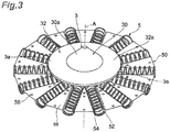
- FIG. 3 is a perspective view illustrating the distributing table and the conveying portions.
- the distributing table 3 is in a circular shape in a plan view.
- the distributing table 3 has a first distributing portion 30 and a second distributing portion 32.
- the first distributing portion 30 is in a cone shape with its center positioned at a central axis A.
- the first distributing portion 30 has a conveying face (outside face) 30a.
- the first distributing portion 30 is connected to the second distributing portion 32 on its bottom portion.
- the second distributing portion 32 is in a shape of cone that has a vertex angle larger than that of the first distributing portion 30 whose vertex portion is removed. At a position that corresponds to the removed vertex portion, the second distributing portion 32 is connected to the first distributing portion 30.
- a conveying face 32a of the second distributing portion 32 is different in inclination from the conveying face 30a of the first distributing portion 30. Due to this, an inclination of a conveying face 3a of the distributing table 3 changes at a connection portion of the first distributing portion 30 and the second distributing portion 32.
- the distributing table 3 is attached to a rotating axis 6 (refer to FIG. 4 ) supported by a supporting portion 4 (refer to FIG. 4 ).
- the distributing table 3 is detachable with respect to the rotating axis 6.
- a motor that is not illustrated here drives the rotating axis 6.
- the distributing table 3 rotates (normal and reverse rotations) around the central axis A by the motor. By rotating around the central axis A, the distributing table 3 conveys (distributes) the weighed object M fed on the distributing table 3 in a direction towards an outer edge portion 3e of the conveying face 3a of the distributing table 3.
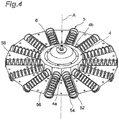
- FIG. 4 is a perspective view illustrating the conveying portion.
- the conveying portion 5 includes a trough 52 and a screw 54 arranged in the trough 52.
- the plurality of troughs 52 are formed on a trough plate 50.
- the trough plate 50 is in a circular shape in a plan view.
- An inner diameter of the trough plate 50 is substantially equal to an outer diameter of the supporting portion 4 and is smaller than an outer diameter of the distributing table 3.
- An inner circumference edge of the trough plate 50 is positioned inward than the outer edge portion 3e of the distributing table 3 when seen from the above along the central axis A.
- the trough 52 is a recessed portion (recessed shaped groove) in a semicircular column shape.
- the trough 52 is arranged in a radial manner from the center (the central axis A) of the trough plate 50.
- the trough 52 extends from the center to an outer edge of the trough plate 50.
- a connecting portion 56 that connects the troughs 52 is arranged between the troughs 52 adjacent to each other in a circumferential direction of the trough plate 50.
- the connecting portion 56 is in a triangle shape in which the inner circumference edge side is the vertex.
- the connecting portion 56 is a flat surface.
- Each of the connecting portions 56 has a plurality of (three in this case) engaging bosses 58 for engaging the guide ring 9.
- the screw 54 is arranged in each of the troughs 52.
- a motor (not illustrated) arranged inside a wall portion 4a corresponding to the trough 52 in the supporting portion 4, the screw 54 is driven and rotates.
- the conveying portion 5, which includes the trough 52 and the screw 54, is arranged in a radial manner along the outer edge portion 3e of the distributing table 3. Then the conveying portion 5 conveys the weighed object M discharged from the distributing table 3 along the trough 52 by the screw 54 that is rotating.
- An edge portion of the distributing table 3 side of the conveying portion 5 is an introducing portion 59 for the weighed object M.
- the hopper 7 is provided corresponding to each of the conveying portions 5. Then the hopper 7 receives the weighed object M that has been discharged from the conveying portion 5. More specifically, the hopper 7 includes a pool hopper 70, a weighing hopper 72, and a booster hopper 74. The pool hopper 70, the weighing hopper 72, and the booster hopper 74 are arranged in this order from an upper side toward a lower side.
- the pool hopper 70 temporarily holds the weighed object M that has been discharged from the conveying portion 5.
- the weighing hopper 72 temporarily holds the weighed object M that has been discharged from the pool hopper 70.
- the weighing hopper 72 is connected with a weighing apparatus that is not illustrated. Then this weighing apparatus weighs mass of the weighed object M.
- the booster hopper 74 temporarily holds the weighed object M that has been discharged from the weighing hopper 72.
- the set of the pool hopper 70, the weighing hopper 72, and the booster hopper 74 are arranged corresponding to each of the conveying portions 5.
- FIG. 5 is a perspective view illustrating the guide ring.
- the guide ring 9 includes a plurality of guide blocks (dividing portions) 90 arranged in a radial manner along the outer edge portion 3e of the distributing table 3.
- the guide block 90 is in a trapezoidal shape whose upper side is an edge portion 92 on the outer edge portion 3e side of the distributing table 3 in a plan view.
- a connecting portion 93 connects the guide blocks 90 adjacent to each other.
- a lower portion of the edge portion 92 of the guide block 90 is provided with a projecting portion 94 that projects inward than an edge face 92a.
- An upper face 94a of the projecting portion 94 is a flat surface.
- the guide block 90 is arranged on the connecting portion 56 of the trough plate 50.
- the engaging boss 58 of the connecting portion 56 is fitted in an engaging hole (not illustrated) provided on a bottom face of the guide block 90.
- the guide block 90 is engaged in the connecting portion 56 of the trough plate 50.
- the distributing table 3 is attached to the rotating axis 6.
- the projecting portion 94 of the guide block 90 is positioned inward than the outer edge portion 3e of the distributing table 3 when seen from the above along the central axis A. As illustrated in FIG. 6 , there is a gap formed between the edge face 92a of the edge portion 92 of the guide block 90 and the outer edge portion 3e of the distributing table 3.
- the guide block 90 Since the guide block 90 is arranged on the trough plate 50, side walls 90a of the guide blocks 90 adjacent to each other form an area that has a width corresponding to a width of the trough 52 on each of the conveying portions 5.
- the edge portion 92 of the guide block 90 forms the introducing portion (introducing opening) 59 through which the weighed object M is introduced to the conveying portions 5.
- FIG. 7 is a magnified view of the edge portion of the guide block.
- the edge face 92a of the edge portion 92 of the outer edge portion 3e side of the distributing table 3 is a flat surface, viewed from a direction along the central axis A.
- the edge face 92a is opposed to an edge face of the outer edge portion 3e of the distributing table 3.
- a width W 1 of the edge portion 92 of the guide block 90 has a length equal to or greater than 1/4 of a width W2 of the trough 52 for example.
- the width W1 of the edge portion 92 has a length equal to or greater than 1/22 of a diameter R (refer to FIG. 6 ) of the distributing table 3 for instance.
- the width W1 of the edge portion 92 may be set as appropriate in accordance with a design request desired by a designer.
- the weighed object M contacts the outer edge portion 3e at a plurality of points when the weighed object M is positioned between the outer edge portion 3e of the distributing table 3 and the edge portion 92. More specifically, as illustrated in FIG. 8 , for example, when the weighed object M is across the conveying portions 5 adjacent to each other and positioned between the outer edge portion 3e of the distributing table 3 and the edge portion 92, the weighed object M contacts the outer edge portion 3e due to an action of the edge portion 92. At this moment, the weighed object M contacts the outer edge portion 3e at a plurality of points in a section of a region R1 enclosed by the chained line in FIG. 8 .
- FIG. 9 is a view illustrating the weighed object stuck between an edge portion of a conventional guide block and the distributing table.
- an edge portion 102 of a conventional guide block 100 is in a projecting form tapered towards the distributing table 3.
- the weighed object M contacts the outer edge portion 3e of the distributing table 3 at a point P (indicated by the black circle in FIG. 9 ) in a section of a region R2 enclosed by the chained line in FIG. 9 .
- an area where the distributing table 3 and the weighed object M contact each other is smaller than that in a case where the weighed object M contacts at a plurality of points.
- a force by rotation of the distributing table 3 is not effectively transmitted to the weighed object M.
- the weighed object M remains between the distributing table 3 and the edge portion 102 of the guide block 100.
- the combination weighing apparatus 1 acts in a following manner. As specifically illustrated in FIG. 8 , due to an action of the edge face 92a formed in the edge portion 92 of the outer edge portion 3e side of the guide block 90, the weighed object M contacts the outer edge portion 3e at, for instance, a plurality of points P (four points in FIG. 8 ). More specifically, the edge portion 92 contacts at the edge face 92a the weighed object M that is across the conveying portions 5 adjacent to each other, so as to cause the weighed object M to extend between the outer edge portion 3e of the distributing table 3 and the edge portion 92 by a width of the edge face 92a.
- the outer edge portion 3e side of the edge portion 92 of the guide block 90 is a flat surface. In this way, if the edge portion 92 is a flat surface, the weighed object M contacts the outer edge portion 3e at a plurality of points when the weighed object M is stuck between the edge portion 92 and the outer edge portion 3e.
- the combination weighing apparatus 1 weighs the weighed object M such as raw meat that has adhesiveness.
- the weighed object M has adhesiveness
- an edge face 92Aa of an edge portion 92A of a guide block 90A may be in a form of being along the outer edge portion 3e of the distributing table 3 for example.
- the weighed object M extends along the edge face 92Aa by a width of the edge face 92Aa when the weighed object M is stuck between the edge portion 92A and the outer edge portion 3e. Due to this, a length where the weighed object M extends with respect to the outer edge portion 3e becomes larger than that to the edge portion 102 illustrated in FIG. 9 . As a result, the weighed object M has more contact points with the outer edge portion 3e and contacts the outer edge portion 3e at a plurality of points.
- an edge face 92Ba of an edge portion 92B of a guide block 90B may be a projecting curved face towards the distributing table 3 side for instance.
- the edge face 92Ba is a gentle curved face.
- the weighed object M extends along the edge face 92Ba by a width of the edge face 92Ba when the weighed object M is stuck between the edge portion 92B and the outer edge portion 3e. Due to this, a length where the weighed object M extends with respect to the outer edge portion 3e becomes larger than that to the edge portion 102 illustrated in FIG. 9 .
- the weighed object M has more contact points with the outer edge portion 3e and contacts the outer edge portion 3e at a plurality of points.
- an edge portion 92C of a guide block 90C may be in a polygonal shape.
- the edge portion 92C at least an edge face 92Ca opposite to the edge face of the outer edge portion 3e of the distributing table 3 is a flat surface.
- the weighed object M extends along the edge face 92Ca by a width of the edge face 92Ca when the weighed object M is stuck between the edge portion 92C and the outer edge portion 3e. Due to this, a length where the weighed object M extends with respect to the outer edge portion 3e becomes larger than that to the edge portion 102 illustrated in FIG. 9 .
- the weighed object M has more contact points with the outer edge portion 3e and contacts the outer edge portion 3e at a plurality of points.
- an edge portion 92D of a guide block 90D may be in a trapezoidal shape.
- the edge portion 92D at least an edge face 92Da opposite to the edge face of the outer edge portion 3e of the distributing table 3 is a flat surface.
- the weighed object M extends along the edge face 92Da by a width of the edge face 92Da when the weighed object M is stuck between the edge portion 92D and the outer edge portion 3e. Due to this, a length where the weighed object M extends with respect to the outer edge portion 3e becomes larger than that to the edge portion 102 illustrated in FIG. 9 .
- the weighed object M has more contact points with the outer edge portion 3e and contacts the outer edge portion 3e at a plurality of points.
- the distributing table 3 may be in a form in which the weighed object is conveyed towards the outer edge portion 3e by vibration.
- the guide blocks 90 may not be connected with each other.
- the configuration of the distributing table 3 is not limited to it.
Landscapes
- Physics & Mathematics (AREA)
- General Physics & Mathematics (AREA)
- Weight Measurement For Supplying Or Discharging Of Specified Amounts Of Material (AREA)
- Filling Or Emptying Of Bunkers, Hoppers, And Tanks (AREA)
- Feeding Of Articles To Conveyors (AREA)
- Branching, Merging, And Special Transfer Between Conveyors (AREA)
Description
- The present invention relates to a combination weighing apparatus.
- The patent literature 1 discloses a combination weighing apparatus. This combination weighing apparatus includes a distributing portion that rotates to convey a weighed object outward, a plurality of conveying portions arranged in a radial manner along a circumference of the distributing portion and convey the weighed object discharged from the distributing portion by a rotating screw, a dividing portion arranged between the conveying portions and forms an introducing portion of the weighed object in the conveying portions, a plurality of hoppers that are provided corresponding to each conveying portion and receive the weighed object that has been discharged from the conveying portion, and a plurality of weighing hoppers arranged below the plurality of hoppers.
- Patent Literature 1: Japanese Unexamined Patent Publication No.
2014-509290 - As the combination weighing apparatus described above, in a configuration where a dividing portion is arranged between conveying portions, a weighed object may be stuck in the dividing portion in a state of being across two conveying portions depending on a form of the weighed object. In order to avoid such an event, an edge portion of a distributing portion side of the dividing portion is normally in a form in which the weighed object is guided to an introducing portion of the conveying portion (form in which the weighed object easily enters the introducing portion). More specifically, the edge portion of the dividing portion is in a very small form in width as the apparatus stated in the patent literature 1 or in a projecting form tapered towards the distributing portion side.
- The weighed object may be stuck between the distributing portion and the edge portion of the dividing portion. At this moment, in a form of a conventional edge portion of the dividing portion, an area where the edge portion and the weighed object contact each other is small, and hence an area where the weighed object and the distributing portion contact each other is also small. For this reason, a force by rotation of the distributing portion may not be effectively transmitted to the weighed object and the weighed object may remain between the distributing portion and the edge portion of the dividing portion.
- The present invention is intended to provide a combination weighing apparatus that can prevent a weighed object from remaining between the distributing portion and the dividing portion.
- A combination weighing apparatus according to an aspect of the present invention includes a distributing portion that rotates to convey a weighed object outward, a plurality of conveying portions arranged in a radial manner along an outer edge portion of the distributing portion and convey the weighed object discharged from the distributing portion, and a dividing portion arranged between the conveying portions, in which an edge portion of the outer edge portion side of the dividing portion causes the weighed object to contact the outer edge portion at a plurality of points when the weighed object is positioned between the outer edge portion and the edge portion.
- The edge portion of the outer edge portion side of the dividing portion included in the combination weighing apparatus causes the weighed object to contact the outer edge portion at the plurality of points. Due to this, when the weighed object is stuck between the outer edge portion of the distributing portion and the edge portion, an area where the weighed object and the outer edge portion of the distributing portion contact each other is larger than that in a case where they are not caused to contact each other at the plurality of points. As a result, the force by rotation of the distributing portion is effectively transmitted to the weighed object and the weighed object is pulled out from between the edge portion of the dividing portion and the outer edge portion the distributing portion. Consequently, it is difficult for the weighed object to remain between the distributing portion and the dividing portion.
- In an embodiment, the outer edge portion side of the edge portion may be a flat surface. In this way, if the edge portion is a flat surface, the weighed object can contact the outer edge portion at a plurality of points when the weighed object is stuck between the edge portion and the outer edge portion.
- In an embodiment, the outer edge portion side of the edge portion may be in a form where it is along the outer edge portion. In this way, if the edge portion is in a form where it is along the outer edge portion, for example, an outwardly projecting curved face, the weighed object can be caused to contact the outer edge portion at a plurality of points when the weighed object is stuck between the edge portion and the outer edge portion.
- In an embodiment, the weighed object may have adhesiveness. In a case where the weighed object has adhesiveness, it is easy for the weighed object to get stuck in a gap between the distributing portion and the edge portion of the dividing portion. Therefore, the configuration of the edge portion that causes the weighed object to contact the outer edge portion at a plurality of points is effective particularly in a case of weighing the weighed object that has adhesiveness. It is to be noted that the weighed object that has adhesiveness is meat for instance.
- The present invention can prevent the weighed object from remaining between the distributing portion and the dividing portion.
-
-
FIG. 1 is a schematic perspective view of a combination weighing apparatus according to an embodiment. -
FIG. 2 is a schematic perspective view in a case where a guide ring of the combination weighing apparatus illustrated inFIG. 1 is omitted. -
FIG. 3 is a perspective view illustrating a distributing table and a conveying portion. -
FIG. 4 is a perspective view illustrating the conveying portion. -
FIG. 5 is a perspective view illustrating the guide ring. -
FIG. 6 is an upper view of the combination weighing apparatus illustrated inFIG. 1 . -
FIG. 7 is a magnified view of an edge portion of a guide block. -
FIG. 8 is a view illustrating a weighed object stuck between the edge portion of the guide block and the distributing table. -
FIG. 9 is a view illustrating a weighed object stuck between an edge portion of a conventional guide block and the distributing table. -
FIG. 10 is a magnified view of the edge portion of the guide block according to another embodiment. -
FIG. 11 is a magnified view of the edge portion of the guide block according to another embodiment. - A detailed description of a preferred embodiment of the present invention will now be given with reference to the drawings. It is to be noted that in the description of the drawings, identical or corresponding elements are designated by the same reference numerals and overlapping descriptions will be omitted.
-
FIG. 1 is a schematic perspective view of a combination weighing apparatus according to an embodiment. -
FIG. 2 is a schematic perspective view in a case where a guide ring of the combination weighing apparatus illustrated inFIG. 1 is omitted. - A combination weighing apparatus 1 illustrated in
FIG. 1 andFIG. 2 weighs out a weighed object M (refer toFIG. 8 ), each of which has a different mass, so that a total mass falls within an acceptable range. Here, the weighed object M includes raw meat such as beef, pork, and chicken. The combination weighing apparatus 1 of the present embodiment can preferably weigh articles having adhesiveness in particular. - As illustrated in
FIG. 1 andFIG. 2 , the combination weighing apparatus 1 includes a distributing table (distributing portion) 3, a plurality of conveyingportions 5, a plurality ofhoppers 7, and aguide ring 9. The distributing table 3, the conveyingportions 5, thehoppers 7, and theguide ring 9 are supported by aframe 10. -
FIG. 3 is a perspective view illustrating the distributing table and the conveying portions. As illustrated inFIG. 1 to FIG. 3 , the distributing table 3 is in a circular shape in a plan view. The distributing table 3 has a first distributingportion 30 and a second distributingportion 32. The first distributingportion 30 is in a cone shape with its center positioned at a central axis A. The first distributingportion 30 has a conveying face (outside face) 30a. The first distributingportion 30 is connected to the second distributingportion 32 on its bottom portion. - The second distributing
portion 32 is in a shape of cone that has a vertex angle larger than that of the first distributingportion 30 whose vertex portion is removed. At a position that corresponds to the removed vertex portion, the second distributingportion 32 is connected to the first distributingportion 30. A conveyingface 32a of the second distributingportion 32 is different in inclination from the conveyingface 30a of the first distributingportion 30. Due to this, an inclination of a conveyingface 3a of the distributing table 3 changes at a connection portion of the first distributingportion 30 and the second distributingportion 32. - The distributing table 3 is attached to a rotating axis 6 (refer to
FIG. 4 ) supported by a supporting portion 4 (refer toFIG. 4 ). The distributing table 3 is detachable with respect to the rotatingaxis 6. A motor that is not illustrated here drives therotating axis 6. The distributing table 3 rotates (normal and reverse rotations) around the central axis A by the motor. By rotating around the central axis A, the distributing table 3 conveys (distributes) the weighed object M fed on the distributing table 3 in a direction towards anouter edge portion 3e of the conveyingface 3a of the distributing table 3. -
FIG. 4 is a perspective view illustrating the conveying portion. As illustrated inFIG. 2 to FIG. 4 , the conveyingportion 5 includes atrough 52 and ascrew 54 arranged in thetrough 52. The plurality oftroughs 52 are formed on atrough plate 50. Thetrough plate 50 is in a circular shape in a plan view. An inner diameter of thetrough plate 50 is substantially equal to an outer diameter of the supportingportion 4 and is smaller than an outer diameter of the distributing table 3. An inner circumference edge of thetrough plate 50 is positioned inward than theouter edge portion 3e of the distributing table 3 when seen from the above along the central axis A. - The
trough 52 is a recessed portion (recessed shaped groove) in a semicircular column shape. Thetrough 52 is arranged in a radial manner from the center (the central axis A) of thetrough plate 50. Thetrough 52 extends from the center to an outer edge of thetrough plate 50. - Here, a connecting
portion 56 that connects thetroughs 52 is arranged between thetroughs 52 adjacent to each other in a circumferential direction of thetrough plate 50. The connectingportion 56 is in a triangle shape in which the inner circumference edge side is the vertex. In addition, the connectingportion 56 is a flat surface. Each of the connectingportions 56 has a plurality of (three in this case) engagingbosses 58 for engaging theguide ring 9. - The
screw 54 is arranged in each of thetroughs 52. By a motor (not illustrated) arranged inside awall portion 4a corresponding to thetrough 52 in the supportingportion 4, thescrew 54 is driven and rotates. The conveyingportion 5, which includes thetrough 52 and thescrew 54, is arranged in a radial manner along theouter edge portion 3e of the distributing table 3. Then the conveyingportion 5 conveys the weighed object M discharged from the distributing table 3 along thetrough 52 by thescrew 54 that is rotating. An edge portion of the distributing table 3 side of the conveyingportion 5 is an introducingportion 59 for the weighed object M. - As illustrated in
FIG. 1 andFIG. 2 , thehopper 7 is provided corresponding to each of the conveyingportions 5. Then thehopper 7 receives the weighed object M that has been discharged from the conveyingportion 5. More specifically, thehopper 7 includes apool hopper 70, a weighinghopper 72, and abooster hopper 74. Thepool hopper 70, the weighinghopper 72, and thebooster hopper 74 are arranged in this order from an upper side toward a lower side. - The
pool hopper 70 temporarily holds the weighed object M that has been discharged from the conveyingportion 5. The weighinghopper 72 temporarily holds the weighed object M that has been discharged from thepool hopper 70. The weighinghopper 72 is connected with a weighing apparatus that is not illustrated. Then this weighing apparatus weighs mass of the weighed object M. Thebooster hopper 74 temporarily holds the weighed object M that has been discharged from the weighinghopper 72. In the above, the set of thepool hopper 70, the weighinghopper 72, and thebooster hopper 74 are arranged corresponding to each of the conveyingportions 5. -
FIG. 5 is a perspective view illustrating the guide ring. As illustrated inFIG. 1 andFIG. 5 , theguide ring 9 includes a plurality of guide blocks (dividing portions) 90 arranged in a radial manner along theouter edge portion 3e of the distributing table 3. Theguide block 90 is in a trapezoidal shape whose upper side is anedge portion 92 on theouter edge portion 3e side of the distributing table 3 in a plan view. Here, a connectingportion 93 connects the guide blocks 90 adjacent to each other. A lower portion of theedge portion 92 of theguide block 90 is provided with a projecting portion 94 that projects inward than anedge face 92a. An upper face 94a of the projecting portion 94 is a flat surface. - The
guide block 90 is arranged on the connectingportion 56 of thetrough plate 50. At this time, the engagingboss 58 of the connectingportion 56 is fitted in an engaging hole (not illustrated) provided on a bottom face of theguide block 90. As a result, theguide block 90 is engaged in the connectingportion 56 of thetrough plate 50. After theguide ring 9 is arranged on thetrough plate 50, the distributing table 3 is attached to therotating axis 6. The projecting portion 94 of theguide block 90 is positioned inward than theouter edge portion 3e of the distributing table 3 when seen from the above along the central axis A. As illustrated inFIG. 6 , there is a gap formed between theedge face 92a of theedge portion 92 of theguide block 90 and theouter edge portion 3e of the distributing table 3. - Since the
guide block 90 is arranged on thetrough plate 50,side walls 90a of the guide blocks 90 adjacent to each other form an area that has a width corresponding to a width of thetrough 52 on each of the conveyingportions 5. Theedge portion 92 of theguide block 90 forms the introducing portion (introducing opening) 59 through which the weighed object M is introduced to the conveyingportions 5. With this configuration, the weighed object M that is conveyed by the distributing table 3 is guided to the conveyingportions 5 by theguide block 90 and thus introduced into the conveyingportions 5. -
FIG. 7 is a magnified view of the edge portion of the guide block. As illustrated inFIG. 7 , in theguide block 90, theedge face 92a of theedge portion 92 of theouter edge portion 3e side of the distributing table 3 is a flat surface, viewed from a direction along the central axis A. Theedge face 92a is opposed to an edge face of theouter edge portion 3e of the distributing table 3. A width W1 of theedge portion 92 of theguide block 90 has a length equal to or greater than 1/4 of a width W2 of thetrough 52 for example. Alternatively, the width W1 of theedge portion 92 has a length equal to or greater than 1/22 of a diameter R (refer toFIG. 6 ) of the distributing table 3 for instance. In short, the width W1 of theedge portion 92 may be set as appropriate in accordance with a design request desired by a designer. - In a case where the configuration described above is provided, the weighed object M contacts the
outer edge portion 3e at a plurality of points when the weighed object M is positioned between theouter edge portion 3e of the distributing table 3 and theedge portion 92. More specifically, as illustrated inFIG. 8 , for example, when the weighed object M is across the conveyingportions 5 adjacent to each other and positioned between theouter edge portion 3e of the distributing table 3 and theedge portion 92, the weighed object M contacts theouter edge portion 3e due to an action of theedge portion 92. At this moment, the weighed object M contacts theouter edge portion 3e at a plurality of points in a section of a region R1 enclosed by the chained line inFIG. 8 . -
FIG. 9 is a view illustrating the weighed object stuck between an edge portion of a conventional guide block and the distributing table. As illustrated inFIG. 9 , anedge portion 102 of aconventional guide block 100 is in a projecting form tapered towards the distributing table 3. In a case where this configuration is provided, when the weighed object M is positioned between theouter edge portion 3e of the distributing table 3 and theedge portion 102, the weighed object M contacts theouter edge portion 3e of the distributing table 3 at a point P (indicated by the black circle inFIG. 9 ) in a section of a region R2 enclosed by the chained line inFIG. 9 . For this reason, an area where the distributing table 3 and the weighed object M contact each other is smaller than that in a case where the weighed object M contacts at a plurality of points. As a result, a force by rotation of the distributing table 3 is not effectively transmitted to the weighed object M. Thus, the weighed object M remains between the distributing table 3 and theedge portion 102 of theguide block 100. - On the other hand, the combination weighing apparatus 1 acts in a following manner. As specifically illustrated in
FIG. 8 , due to an action of theedge face 92a formed in theedge portion 92 of theouter edge portion 3e side of theguide block 90, the weighed object M contacts theouter edge portion 3e at, for instance, a plurality of points P (four points inFIG. 8 ). More specifically, theedge portion 92 contacts at theedge face 92a the weighed object M that is across the conveyingportions 5 adjacent to each other, so as to cause the weighed object M to extend between theouter edge portion 3e of the distributing table 3 and theedge portion 92 by a width of theedge face 92a. Due to this, compared with the conventional configuration described above, an area where the weighed object M and theouter edge portion 3e of the distributing table 3 contact each other is larger. Consequently, a force by rotation of the distributing table 3 is effectively transmitted to the weighed object M. As a result, it becomes easy for the weighed object M to be pulled out from between theedge portion 92 of theguide block 90 and theouter edge portion 3e of the distributing table 3. Hence, it can be made difficult for the weighed object M to remain between the distributing table 3 and theguide block 90. - In the present embodiment, the
outer edge portion 3e side of theedge portion 92 of theguide block 90 is a flat surface. In this way, if theedge portion 92 is a flat surface, the weighed object M contacts theouter edge portion 3e at a plurality of points when the weighed object M is stuck between theedge portion 92 and theouter edge portion 3e. - In the present embodiment, the combination weighing apparatus 1 weighs the weighed object M such as raw meat that has adhesiveness. In a case where the weighed object M has adhesiveness, it is easy for the weighed object M to get stuck in a gap between the distributing table 3 and the
edge portion 92 of theguide block 90. Therefore, the configuration of theedge portion 92 of theguide block 90 that causes the weighed object M to contact theouter edge portion 3e at a plurality of points is effective particularly in a case of weighing the weighed object M that has adhesiveness. - The present invention is not limited to the embodiment described above. While in the embodiment described above, the description has been made with an example of the form in which the
edge face 92a of theedge portion 92 of theguide block 90 is a flat surface, the configuration of theedge portion 92 is not limited to it. As illustrated inFIG.10(a) , an edge face 92Aa of anedge portion 92A of aguide block 90A may be in a form of being along theouter edge portion 3e of the distributing table 3 for example. For instance, given that the edge face 92Aa is an outwardly projecting curved face, the weighed object M extends along the edge face 92Aa by a width of the edge face 92Aa when the weighed object M is stuck between theedge portion 92A and theouter edge portion 3e. Due to this, a length where the weighed object M extends with respect to theouter edge portion 3e becomes larger than that to theedge portion 102 illustrated inFIG. 9 . As a result, the weighed object M has more contact points with theouter edge portion 3e and contacts theouter edge portion 3e at a plurality of points. - As illustrated in
FIG. 10(b) , an edge face 92Ba of anedge portion 92B of aguide block 90B may be a projecting curved face towards the distributing table 3 side for instance. The edge face 92Ba is a gentle curved face. In this way, given that the edge face 92Ba is a gentle curved face, the weighed object M extends along the edge face 92Ba by a width of the edge face 92Ba when the weighed object M is stuck between theedge portion 92B and theouter edge portion 3e. Due to this, a length where the weighed object M extends with respect to theouter edge portion 3e becomes larger than that to theedge portion 102 illustrated inFIG. 9 . As a result, the weighed object M has more contact points with theouter edge portion 3e and contacts theouter edge portion 3e at a plurality of points. - As illustrated in
FIG. 11(a) , anedge portion 92C of a guide block 90C may be in a polygonal shape. In theedge portion 92C, at least an edge face 92Ca opposite to the edge face of theouter edge portion 3e of the distributing table 3 is a flat surface. In this way, given that theedge portion 92C is in a polygonal shape, the weighed object M extends along the edge face 92Ca by a width of the edge face 92Ca when the weighed object M is stuck between theedge portion 92C and theouter edge portion 3e. Due to this, a length where the weighed object M extends with respect to theouter edge portion 3e becomes larger than that to theedge portion 102 illustrated inFIG. 9 . As a result, the weighed object M has more contact points with theouter edge portion 3e and contacts theouter edge portion 3e at a plurality of points. - As illustrated in FIG. new), an
edge portion 92D of aguide block 90D may be in a trapezoidal shape. In theedge portion 92D, at least an edge face 92Da opposite to the edge face of theouter edge portion 3e of the distributing table 3 is a flat surface. In this way, given that theedge portion 92D is in a trapezoidal shape, the weighed object M extends along the edge face 92Da by a width of the edge face 92Da when the weighed object M is stuck between theedge portion 92D and theouter edge portion 3e. Due to this, a length where the weighed object M extends with respect to theouter edge portion 3e becomes larger than that to theedge portion 102 illustrated inFIG. 9 . As a result, the weighed object M has more contact points with theouter edge portion 3e and contacts theouter edge portion 3e at a plurality of points. - In the above described embodiment, the description has been made with an example of the form in which the distributing table 3 rotates about the central axis A so that the weighed object is conveyed towards the
outer edge portion 3e. However, the distributing table 3 may be in a form in which the weighed object is conveyed towards theouter edge portion 3e by vibration. - In the above described embodiment, the description has been made with an example of the form in which the weighed object M is conveyed by the
screw 54 in the conveyingportion 5. However, a conveying method in the conveyingportion 5 maybe another method. - In the above described embodiment, the description has been made with an example of the form in which the guide blocks 90 are connected with each other by the connecting
portion 93 in theguide ring 9. However, the guide blocks 90 may not be connected with each other. - While in the above described embodiment, the description has been made with an example of the form in which the distributing table 3 includes the first distributing
portion 30 and the second distributingportion 32, the configuration of the distributing table 3 is not limited to it. - [ooh.5] 1: combination weighing apparatus, 3: distributing table (distributing portion), 3e: outer edge portion, 5: conveying portion, 9: guide ring (dividing portion), 92, 92A, 92B, 92C, 92D: edge portion, M: weighed object
Claims (4)
- A combination weighing apparatus, comprising: a distributing portion that rotates to convey a weighed object outward, a plurality of conveying portions arranged in a radial manner along an outer edge portion of the distributing portion and convey the weighed object discharged from the distributing portion, and a dividing portion arranged between the conveying portions, wherein an edge portion of the outer edge portion side of the dividing portion causes the weighed object to contact the outer edge portion at a plurality of points when the weighed object is positioned between the outer edge portion and the edge portion.
- The combination weighing apparatus according to claim 1, wherein the outer edge portion side of the edge portion is a flat surface.
- The combination weighing apparatus according to claim 1, wherein the outer edge portion side of the edge portion is in a form of being along the outer edge portion.
- The combination weighing apparatus according to any one of claims 1 to 3, wherein the weighed object has adhesiveness.
Applications Claiming Priority (2)
| Application Number | Priority Date | Filing Date | Title |
|---|---|---|---|
| JP2014148053A JP6377982B2 (en) | 2014-07-18 | 2014-07-18 | Combination weighing device |
| PCT/JP2015/069513 WO2016009896A1 (en) | 2014-07-18 | 2015-07-07 | Combination weighing device |
Publications (3)
| Publication Number | Publication Date |
|---|---|
| EP3171141A1 true EP3171141A1 (en) | 2017-05-24 |
| EP3171141A4 EP3171141A4 (en) | 2018-03-14 |
| EP3171141B1 EP3171141B1 (en) | 2020-05-27 |
Family
ID=55078392
Family Applications (1)
| Application Number | Title | Priority Date | Filing Date |
|---|---|---|---|
| EP15822444.4A Active EP3171141B1 (en) | 2014-07-18 | 2015-07-07 | Combination weighing device |
Country Status (4)
| Country | Link |
|---|---|
| EP (1) | EP3171141B1 (en) |
| JP (1) | JP6377982B2 (en) |
| DK (1) | DK3171141T3 (en) |
| WO (1) | WO2016009896A1 (en) |
Family Cites Families (3)
| Publication number | Priority date | Publication date | Assignee | Title |
|---|---|---|---|---|
| JP2011209156A (en) * | 2010-03-30 | 2011-10-20 | Ishida Co Ltd | Combination weighing device |
| EP2484593A1 (en) * | 2011-02-04 | 2012-08-08 | Cabinplant International A/S | An apparatus for conveying and selectively discharging products |
| US20130186696A1 (en) * | 2012-01-25 | 2013-07-25 | Marel A/S | Combination weigher |
-
2014
- 2014-07-18 JP JP2014148053A patent/JP6377982B2/en active Active
-
2015
- 2015-07-07 EP EP15822444.4A patent/EP3171141B1/en active Active
- 2015-07-07 DK DK15822444.4T patent/DK3171141T3/en active
- 2015-07-07 WO PCT/JP2015/069513 patent/WO2016009896A1/en not_active Ceased
Also Published As
| Publication number | Publication date |
|---|---|
| DK3171141T3 (en) | 2020-08-10 |
| JP6377982B2 (en) | 2018-08-22 |
| WO2016009896A1 (en) | 2016-01-21 |
| JP2016024039A (en) | 2016-02-08 |
| EP3171141A4 (en) | 2018-03-14 |
| EP3171141B1 (en) | 2020-05-27 |
Similar Documents
| Publication | Publication Date | Title |
|---|---|---|
| EP3112825B1 (en) | Combination weighing apparatus | |
| WO2017051350A3 (en) | Machine to manufacture cartridges for electronic cigarettes and plant for the production of packages containing said cartridges for electronic cigarettes | |
| CN108889639B (en) | Flexible vibration disk | |
| EP3171140B1 (en) | Combination weighing device | |
| US4596327A (en) | Distributive feeding device for combination weighing machine | |
| EP3171141B1 (en) | Combination weighing device | |
| CN204872761U (en) | High -speed thumb wheel location feed arrangement | |
| CN107708865B (en) | Broken shell with swivel lock | |
| CN105644841B (en) | A kind of blanking device of mounted box robot | |
| GB1104548A (en) | Agitating apparatus | |
| US20160068346A1 (en) | Apparatus and method for transferring eggs | |
| JP6183722B2 (en) | Tangled parts separator | |
| US20240280398A1 (en) | Weighing apparatus | |
| JPWO2016199870A1 (en) | Combination weighing device | |
| US20220313601A1 (en) | Apparatus and method for forming nicotine gum | |
| JP2014145742A (en) | Combination weighing apparatus and method for using the same | |
| EP3385684B1 (en) | Combination weighing apparatus | |
| JP2015215271A (en) | Weighing device | |
| JP5855308B1 (en) | Combination weighing device | |
| CN104544504A (en) | Pepper sorting machine | |
| KR101754808B1 (en) | box supporter having function of the fork | |
| CN204953294U (en) | High temperature resistant pouring material screening machine | |
| EP1935259B1 (en) | Device for peeling vegetables or fruit | |
| CN107031876A (en) | A kind of distributing conveying mechanism of tablet packaging machine | |
| JP2016102798A (en) | Combination weighing apparatus |
Legal Events
| Date | Code | Title | Description |
|---|---|---|---|
| STAA | Information on the status of an ep patent application or granted ep patent |
Free format text: STATUS: THE INTERNATIONAL PUBLICATION HAS BEEN MADE |
|
| PUAI | Public reference made under article 153(3) epc to a published international application that has entered the european phase |
Free format text: ORIGINAL CODE: 0009012 |
|
| STAA | Information on the status of an ep patent application or granted ep patent |
Free format text: STATUS: REQUEST FOR EXAMINATION WAS MADE |
|
| 17P | Request for examination filed |
Effective date: 20170126 |
|
| AK | Designated contracting states |
Kind code of ref document: A1 Designated state(s): AL AT BE BG CH CY CZ DE DK EE ES FI FR GB GR HR HU IE IS IT LI LT LU LV MC MK MT NL NO PL PT RO RS SE SI SK SM TR |
|
| AX | Request for extension of the european patent |
Extension state: BA ME |
|
| DAV | Request for validation of the european patent (deleted) | ||
| DAX | Request for extension of the european patent (deleted) | ||
| A4 | Supplementary search report drawn up and despatched |
Effective date: 20180208 |
|
| RIC1 | Information provided on ipc code assigned before grant |
Ipc: G01G 19/387 20060101AFI20180202BHEP Ipc: G01G 19/393 20060101ALI20180202BHEP |
|
| STAA | Information on the status of an ep patent application or granted ep patent |
Free format text: STATUS: EXAMINATION IS IN PROGRESS |
|
| 17Q | First examination report despatched |
Effective date: 20190716 |
|
| GRAP | Despatch of communication of intention to grant a patent |
Free format text: ORIGINAL CODE: EPIDOSNIGR1 |
|
| STAA | Information on the status of an ep patent application or granted ep patent |
Free format text: STATUS: GRANT OF PATENT IS INTENDED |
|
| INTG | Intention to grant announced |
Effective date: 20191212 |
|
| GRAS | Grant fee paid |
Free format text: ORIGINAL CODE: EPIDOSNIGR3 |
|
| GRAA | (expected) grant |
Free format text: ORIGINAL CODE: 0009210 |
|
| STAA | Information on the status of an ep patent application or granted ep patent |
Free format text: STATUS: THE PATENT HAS BEEN GRANTED |
|
| AK | Designated contracting states |
Kind code of ref document: B1 Designated state(s): AL AT BE BG CH CY CZ DE DK EE ES FI FR GB GR HR HU IE IS IT LI LT LU LV MC MK MT NL NO PL PT RO RS SE SI SK SM TR |
|
| REG | Reference to a national code |
Ref country code: GB Ref legal event code: FG4D |
|
| REG | Reference to a national code |
Ref country code: CH Ref legal event code: EP |
|
| REG | Reference to a national code |
Ref country code: AT Ref legal event code: REF Ref document number: 1275018 Country of ref document: AT Kind code of ref document: T Effective date: 20200615 |
|
| REG | Reference to a national code |
Ref country code: DE Ref legal event code: R096 Ref document number: 602015053498 Country of ref document: DE |
|
| REG | Reference to a national code |
Ref country code: DK Ref legal event code: T3 Effective date: 20200803 |
|
| REG | Reference to a national code |
Ref country code: NL Ref legal event code: FP |
|
| REG | Reference to a national code |
Ref country code: LT Ref legal event code: MG4D |
|
| PG25 | Lapsed in a contracting state [announced via postgrant information from national office to epo] |
Ref country code: LT Free format text: LAPSE BECAUSE OF FAILURE TO SUBMIT A TRANSLATION OF THE DESCRIPTION OR TO PAY THE FEE WITHIN THE PRESCRIBED TIME-LIMIT Effective date: 20200527 Ref country code: NO Free format text: LAPSE BECAUSE OF FAILURE TO SUBMIT A TRANSLATION OF THE DESCRIPTION OR TO PAY THE FEE WITHIN THE PRESCRIBED TIME-LIMIT Effective date: 20200827 Ref country code: FI Free format text: LAPSE BECAUSE OF FAILURE TO SUBMIT A TRANSLATION OF THE DESCRIPTION OR TO PAY THE FEE WITHIN THE PRESCRIBED TIME-LIMIT Effective date: 20200527 Ref country code: GR Free format text: LAPSE BECAUSE OF FAILURE TO SUBMIT A TRANSLATION OF THE DESCRIPTION OR TO PAY THE FEE WITHIN THE PRESCRIBED TIME-LIMIT Effective date: 20200828 Ref country code: SE Free format text: LAPSE BECAUSE OF FAILURE TO SUBMIT A TRANSLATION OF THE DESCRIPTION OR TO PAY THE FEE WITHIN THE PRESCRIBED TIME-LIMIT Effective date: 20200527 Ref country code: PT Free format text: LAPSE BECAUSE OF FAILURE TO SUBMIT A TRANSLATION OF THE DESCRIPTION OR TO PAY THE FEE WITHIN THE PRESCRIBED TIME-LIMIT Effective date: 20200928 Ref country code: IS Free format text: LAPSE BECAUSE OF FAILURE TO SUBMIT A TRANSLATION OF THE DESCRIPTION OR TO PAY THE FEE WITHIN THE PRESCRIBED TIME-LIMIT Effective date: 20200927 |
|
| PG25 | Lapsed in a contracting state [announced via postgrant information from national office to epo] |
Ref country code: LV Free format text: LAPSE BECAUSE OF FAILURE TO SUBMIT A TRANSLATION OF THE DESCRIPTION OR TO PAY THE FEE WITHIN THE PRESCRIBED TIME-LIMIT Effective date: 20200527 Ref country code: HR Free format text: LAPSE BECAUSE OF FAILURE TO SUBMIT A TRANSLATION OF THE DESCRIPTION OR TO PAY THE FEE WITHIN THE PRESCRIBED TIME-LIMIT Effective date: 20200527 Ref country code: RS Free format text: LAPSE BECAUSE OF FAILURE TO SUBMIT A TRANSLATION OF THE DESCRIPTION OR TO PAY THE FEE WITHIN THE PRESCRIBED TIME-LIMIT Effective date: 20200527 Ref country code: BG Free format text: LAPSE BECAUSE OF FAILURE TO SUBMIT A TRANSLATION OF THE DESCRIPTION OR TO PAY THE FEE WITHIN THE PRESCRIBED TIME-LIMIT Effective date: 20200827 |
|
| REG | Reference to a national code |
Ref country code: AT Ref legal event code: MK05 Ref document number: 1275018 Country of ref document: AT Kind code of ref document: T Effective date: 20200527 |
|
| PG25 | Lapsed in a contracting state [announced via postgrant information from national office to epo] |
Ref country code: AL Free format text: LAPSE BECAUSE OF FAILURE TO SUBMIT A TRANSLATION OF THE DESCRIPTION OR TO PAY THE FEE WITHIN THE PRESCRIBED TIME-LIMIT Effective date: 20200527 |
|
| PG25 | Lapsed in a contracting state [announced via postgrant information from national office to epo] |
Ref country code: CZ Free format text: LAPSE BECAUSE OF FAILURE TO SUBMIT A TRANSLATION OF THE DESCRIPTION OR TO PAY THE FEE WITHIN THE PRESCRIBED TIME-LIMIT Effective date: 20200527 Ref country code: ES Free format text: LAPSE BECAUSE OF FAILURE TO SUBMIT A TRANSLATION OF THE DESCRIPTION OR TO PAY THE FEE WITHIN THE PRESCRIBED TIME-LIMIT Effective date: 20200527 Ref country code: IT Free format text: LAPSE BECAUSE OF FAILURE TO SUBMIT A TRANSLATION OF THE DESCRIPTION OR TO PAY THE FEE WITHIN THE PRESCRIBED TIME-LIMIT Effective date: 20200527 Ref country code: SM Free format text: LAPSE BECAUSE OF FAILURE TO SUBMIT A TRANSLATION OF THE DESCRIPTION OR TO PAY THE FEE WITHIN THE PRESCRIBED TIME-LIMIT Effective date: 20200527 Ref country code: EE Free format text: LAPSE BECAUSE OF FAILURE TO SUBMIT A TRANSLATION OF THE DESCRIPTION OR TO PAY THE FEE WITHIN THE PRESCRIBED TIME-LIMIT Effective date: 20200527 Ref country code: AT Free format text: LAPSE BECAUSE OF FAILURE TO SUBMIT A TRANSLATION OF THE DESCRIPTION OR TO PAY THE FEE WITHIN THE PRESCRIBED TIME-LIMIT Effective date: 20200527 Ref country code: RO Free format text: LAPSE BECAUSE OF FAILURE TO SUBMIT A TRANSLATION OF THE DESCRIPTION OR TO PAY THE FEE WITHIN THE PRESCRIBED TIME-LIMIT Effective date: 20200527 |
|
| PG25 | Lapsed in a contracting state [announced via postgrant information from national office to epo] |
Ref country code: MC Free format text: LAPSE BECAUSE OF FAILURE TO SUBMIT A TRANSLATION OF THE DESCRIPTION OR TO PAY THE FEE WITHIN THE PRESCRIBED TIME-LIMIT Effective date: 20200527 Ref country code: SK Free format text: LAPSE BECAUSE OF FAILURE TO SUBMIT A TRANSLATION OF THE DESCRIPTION OR TO PAY THE FEE WITHIN THE PRESCRIBED TIME-LIMIT Effective date: 20200527 Ref country code: PL Free format text: LAPSE BECAUSE OF FAILURE TO SUBMIT A TRANSLATION OF THE DESCRIPTION OR TO PAY THE FEE WITHIN THE PRESCRIBED TIME-LIMIT Effective date: 20200527 |
|
| REG | Reference to a national code |
Ref country code: CH Ref legal event code: PL |
|
| REG | Reference to a national code |
Ref country code: DE Ref legal event code: R097 Ref document number: 602015053498 Country of ref document: DE |
|
| PLBE | No opposition filed within time limit |
Free format text: ORIGINAL CODE: 0009261 |
|
| STAA | Information on the status of an ep patent application or granted ep patent |
Free format text: STATUS: NO OPPOSITION FILED WITHIN TIME LIMIT |
|
| REG | Reference to a national code |
Ref country code: BE Ref legal event code: MM Effective date: 20200731 |
|
| PG25 | Lapsed in a contracting state [announced via postgrant information from national office to epo] |
Ref country code: IE Free format text: LAPSE BECAUSE OF NON-PAYMENT OF DUE FEES Effective date: 20200707 Ref country code: CH Free format text: LAPSE BECAUSE OF NON-PAYMENT OF DUE FEES Effective date: 20200731 Ref country code: LU Free format text: LAPSE BECAUSE OF NON-PAYMENT OF DUE FEES Effective date: 20200707 Ref country code: LI Free format text: LAPSE BECAUSE OF NON-PAYMENT OF DUE FEES Effective date: 20200731 |
|
| 26N | No opposition filed |
Effective date: 20210302 |
|
| PG25 | Lapsed in a contracting state [announced via postgrant information from national office to epo] |
Ref country code: SI Free format text: LAPSE BECAUSE OF FAILURE TO SUBMIT A TRANSLATION OF THE DESCRIPTION OR TO PAY THE FEE WITHIN THE PRESCRIBED TIME-LIMIT Effective date: 20200527 Ref country code: BE Free format text: LAPSE BECAUSE OF NON-PAYMENT OF DUE FEES Effective date: 20200731 |
|
| PGFP | Annual fee paid to national office [announced via postgrant information from national office to epo] |
Ref country code: NL Payment date: 20210721 Year of fee payment: 7 |
|
| PGFP | Annual fee paid to national office [announced via postgrant information from national office to epo] |
Ref country code: FR Payment date: 20210729 Year of fee payment: 7 |
|
| PG25 | Lapsed in a contracting state [announced via postgrant information from national office to epo] |
Ref country code: TR Free format text: LAPSE BECAUSE OF FAILURE TO SUBMIT A TRANSLATION OF THE DESCRIPTION OR TO PAY THE FEE WITHIN THE PRESCRIBED TIME-LIMIT Effective date: 20200527 Ref country code: MT Free format text: LAPSE BECAUSE OF FAILURE TO SUBMIT A TRANSLATION OF THE DESCRIPTION OR TO PAY THE FEE WITHIN THE PRESCRIBED TIME-LIMIT Effective date: 20200527 Ref country code: CY Free format text: LAPSE BECAUSE OF FAILURE TO SUBMIT A TRANSLATION OF THE DESCRIPTION OR TO PAY THE FEE WITHIN THE PRESCRIBED TIME-LIMIT Effective date: 20200527 |
|
| PG25 | Lapsed in a contracting state [announced via postgrant information from national office to epo] |
Ref country code: MK Free format text: LAPSE BECAUSE OF FAILURE TO SUBMIT A TRANSLATION OF THE DESCRIPTION OR TO PAY THE FEE WITHIN THE PRESCRIBED TIME-LIMIT Effective date: 20200527 |
|
| PGFP | Annual fee paid to national office [announced via postgrant information from national office to epo] |
Ref country code: GB Payment date: 20220721 Year of fee payment: 8 |
|
| REG | Reference to a national code |
Ref country code: NL Ref legal event code: MM Effective date: 20220801 |
|
| PG25 | Lapsed in a contracting state [announced via postgrant information from national office to epo] |
Ref country code: FR Free format text: LAPSE BECAUSE OF NON-PAYMENT OF DUE FEES Effective date: 20220731 |
|
| PG25 | Lapsed in a contracting state [announced via postgrant information from national office to epo] |
Ref country code: NL Free format text: LAPSE BECAUSE OF NON-PAYMENT OF DUE FEES Effective date: 20220801 |
|
| PGFP | Annual fee paid to national office [announced via postgrant information from national office to epo] |
Ref country code: DE Payment date: 20230719 Year of fee payment: 9 |
|
| GBPC | Gb: european patent ceased through non-payment of renewal fee |
Effective date: 20230707 |
|
| PG25 | Lapsed in a contracting state [announced via postgrant information from national office to epo] |
Ref country code: GB Free format text: LAPSE BECAUSE OF NON-PAYMENT OF DUE FEES Effective date: 20230707 |
|
| REG | Reference to a national code |
Ref country code: DE Ref legal event code: R119 Ref document number: 602015053498 Country of ref document: DE |
|
| PG25 | Lapsed in a contracting state [announced via postgrant information from national office to epo] |
Ref country code: DE Free format text: LAPSE BECAUSE OF NON-PAYMENT OF DUE FEES Effective date: 20250201 |
|
| PGFP | Annual fee paid to national office [announced via postgrant information from national office to epo] |
Ref country code: DK Payment date: 20250723 Year of fee payment: 11 |