EP3171057A1 - Sealing device - Google Patents
Sealing device Download PDFInfo
- Publication number
- EP3171057A1 EP3171057A1 EP15821724.0A EP15821724A EP3171057A1 EP 3171057 A1 EP3171057 A1 EP 3171057A1 EP 15821724 A EP15821724 A EP 15821724A EP 3171057 A1 EP3171057 A1 EP 3171057A1
- Authority
- EP
- European Patent Office
- Prior art keywords
- main body
- case main
- sealing
- circumferential surface
- sealing member
- Prior art date
- Legal status (The legal status is an assumption and is not a legal conclusion. Google has not performed a legal analysis and makes no representation as to the accuracy of the status listed.)
- Withdrawn
Links
Images

Classifications
-
- F—MECHANICAL ENGINEERING; LIGHTING; HEATING; WEAPONS; BLASTING
- F16—ENGINEERING ELEMENTS AND UNITS; GENERAL MEASURES FOR PRODUCING AND MAINTAINING EFFECTIVE FUNCTIONING OF MACHINES OR INSTALLATIONS; THERMAL INSULATION IN GENERAL
- F16J—PISTONS; CYLINDERS; SEALINGS
- F16J15/00—Sealings
- F16J15/16—Sealings between relatively-moving surfaces
- F16J15/32—Sealings between relatively-moving surfaces with elastic sealings, e.g. O-rings
- F16J15/3204—Sealings between relatively-moving surfaces with elastic sealings, e.g. O-rings with at least one lip
- F16J15/3232—Sealings between relatively-moving surfaces with elastic sealings, e.g. O-rings with at least one lip having two or more lips
-
- F—MECHANICAL ENGINEERING; LIGHTING; HEATING; WEAPONS; BLASTING
- F16—ENGINEERING ELEMENTS AND UNITS; GENERAL MEASURES FOR PRODUCING AND MAINTAINING EFFECTIVE FUNCTIONING OF MACHINES OR INSTALLATIONS; THERMAL INSULATION IN GENERAL
- F16J—PISTONS; CYLINDERS; SEALINGS
- F16J15/00—Sealings
- F16J15/16—Sealings between relatively-moving surfaces
- F16J15/32—Sealings between relatively-moving surfaces with elastic sealings, e.g. O-rings
- F16J15/3204—Sealings between relatively-moving surfaces with elastic sealings, e.g. O-rings with at least one lip
- F16J15/3216—Sealings between relatively-moving surfaces with elastic sealings, e.g. O-rings with at least one lip supported in a direction parallel to the surfaces
-
- F—MECHANICAL ENGINEERING; LIGHTING; HEATING; WEAPONS; BLASTING
- F16—ENGINEERING ELEMENTS AND UNITS; GENERAL MEASURES FOR PRODUCING AND MAINTAINING EFFECTIVE FUNCTIONING OF MACHINES OR INSTALLATIONS; THERMAL INSULATION IN GENERAL
- F16J—PISTONS; CYLINDERS; SEALINGS
- F16J15/00—Sealings
- F16J15/16—Sealings between relatively-moving surfaces
- F16J15/32—Sealings between relatively-moving surfaces with elastic sealings, e.g. O-rings
- F16J15/3204—Sealings between relatively-moving surfaces with elastic sealings, e.g. O-rings with at least one lip
- F16J15/322—Sealings between relatively-moving surfaces with elastic sealings, e.g. O-rings with at least one lip supported in a direction perpendicular to the surfaces
-
- F—MECHANICAL ENGINEERING; LIGHTING; HEATING; WEAPONS; BLASTING
- F16—ENGINEERING ELEMENTS AND UNITS; GENERAL MEASURES FOR PRODUCING AND MAINTAINING EFFECTIVE FUNCTIONING OF MACHINES OR INSTALLATIONS; THERMAL INSULATION IN GENERAL
- F16J—PISTONS; CYLINDERS; SEALINGS
- F16J15/00—Sealings
- F16J15/16—Sealings between relatively-moving surfaces
- F16J15/32—Sealings between relatively-moving surfaces with elastic sealings, e.g. O-rings
- F16J15/3204—Sealings between relatively-moving surfaces with elastic sealings, e.g. O-rings with at least one lip
- F16J15/3228—Sealings between relatively-moving surfaces with elastic sealings, e.g. O-rings with at least one lip formed by deforming a flat ring
-
- F—MECHANICAL ENGINEERING; LIGHTING; HEATING; WEAPONS; BLASTING
- F16—ENGINEERING ELEMENTS AND UNITS; GENERAL MEASURES FOR PRODUCING AND MAINTAINING EFFECTIVE FUNCTIONING OF MACHINES OR INSTALLATIONS; THERMAL INSULATION IN GENERAL
- F16J—PISTONS; CYLINDERS; SEALINGS
- F16J15/00—Sealings
- F16J15/16—Sealings between relatively-moving surfaces
- F16J15/32—Sealings between relatively-moving surfaces with elastic sealings, e.g. O-rings
- F16J15/3248—Sealings between relatively-moving surfaces with elastic sealings, e.g. O-rings provided with casings or supports
- F16J15/3252—Sealings between relatively-moving surfaces with elastic sealings, e.g. O-rings provided with casings or supports with rigid casings or supports
- F16J15/3256—Sealings between relatively-moving surfaces with elastic sealings, e.g. O-rings provided with casings or supports with rigid casings or supports comprising two casing or support elements, one attached to each surface, e.g. cartridge or cassette seals
-
- F—MECHANICAL ENGINEERING; LIGHTING; HEATING; WEAPONS; BLASTING
- F16—ENGINEERING ELEMENTS AND UNITS; GENERAL MEASURES FOR PRODUCING AND MAINTAINING EFFECTIVE FUNCTIONING OF MACHINES OR INSTALLATIONS; THERMAL INSULATION IN GENERAL
- F16J—PISTONS; CYLINDERS; SEALINGS
- F16J15/00—Sealings
- F16J15/16—Sealings between relatively-moving surfaces
- F16J15/32—Sealings between relatively-moving surfaces with elastic sealings, e.g. O-rings
- F16J15/3268—Mounting of sealing rings
Definitions
- the present invention relates to a sealing device that seals an annular gap between a housing and a shaft.
- FIG. 7 is a schematic cross-sectional view of the sealing device according to the conventional example.
- the illustrated sealing device 700 serves the function of sealing an annular gap between a shaft hole provided in a housing (not shown) and a rotating shaft (not shown) inserted through this shaft hole.
- a resin sealing member 720 and an elastic sealing member 730 made of rubber or the like are fixed to a cartridge case 710 so that they can be handled as one component.
- the cartridge case 710 includes a cylindrical case main body 711 fitted to an inner circumferential surface of the shaft hole, an outward flange 712 extending radially outward from one end portion of the case main body 711 on a sealed fluid side, and an inward flange 713 extending radially inward from an end portion of the case main body 711 opposite from the sealed fluid side.
- the resin sealing member 720 is firmly secured by being held in between a pair of first and second metal supporting members 740 and 750 that are fixedly fitted to each other.
- the elastic sealing member 730 includes an outer peripheral sealing portion 731 that seals an annular gap between the outer circumferential surface of the second supporting member 750 and the inner circumferential surface of the case main body 711, and a sealing lip portion 732 slidable on the outer circumferential surface of the rotating shaft.
- an adapter 760 is press-fitted. Accordingly, the resin sealing member 720 and elastic sealing member 730 are fixedly set in position in the axial direction.
- the distal end of the inward flange 713 is press-joined so that the resin sealing member 720 and elastic sealing member 730 are fixedly set in position in the radial direction (see press-joined portion 714 in the drawing).
- the adapter 760 is press-fitted, as mentioned above. Generally, it is difficult to achieve precise positioning of press-fitted members because of the high sliding resistance during the press-fitting.
- the resin sealing member 720 is firmly secured by the first supporting member 740 and second supporting member 750, and the outer circumferential side of the second supporting member 750 is elastically pressed by the outer peripheral sealing portion 731 of the elastic sealing member 730.
- the resin sealing member 720 is therefore maintained in a stable attitude. Accordingly, the resin sealing member 720 fully exhibits its function.
- the sealing function on the outer circumferential side is also fully exhibited, since the annular gap between the outer circumferential surface of the second supporting member 750 and the inner circumferential surface of the case main body 711 is sealed by the outer peripheral sealing portion 731 of the elastic sealing member 730.
- the illustrated sealing device 700 fully exhibits its function as a sealing device even if the positioning precision of the adapter 760 is low.
- the shortcoming of this sealing device 700 is that the number of parts is large as it requires several components. Generally, with an increase in the number of parts, not only the cost increases, but also measurement errors tend to be large, so that stricter dimension control is necessary.
- Another shortcoming is that it is difficult to reduce the radial size because of the configuration in which the annular gap between the outer circumferential surface of the second supporting member 750 and the inner circumferential surface of the case main body 711 is sealed by the outer peripheral sealing portion 731 of the elastic sealing member 730. It may therefore be impractical to adopt the configuration of the above-described sealing device 700 if the annular gap between the housing and the shaft is small.
- Patent Literature 1 Japanese Patent No. 5037682
- An object of the present invention is to provide a sealing device that can stably exhibit the sealing function and enables a reduction in the number of components as well as in the radial size.
- the present invention adopts the following means to achieve the object noted above.
- a sealing device of the present invention is a sealing device for sealing an annular gap between a shaft hole provided in a housing and a shaft inserted through the shaft hole, the sealing device comprising:
- an outer diameter of the cylindrical portion in the metal fixing member is set to be equal to or smaller than the inner diameter of the case main body, and a configuration is adopted in which the cylindrical portion and case main body are secured by welding. Accordingly, in comparison to the case where the fixing member is secured by press-fitting, the fixing member can be positioned more precisely. Therefore, a separate component dedicated for fixing the resin sealing member in position as was conventionally practiced (such as the first supporting member 740 and second supporting member 750 made of metal in the conventional example described above) is not required. Accordingly, the number of components can be reduced. Moreover, since the fixing member can be positioned more precisely, the attitude of the resin sealing member can be made stable. Thus the sealing function can be exhibited in a stable manner.
- an annular space may be formed between an outer wall surface of a portion connecting the cylindrical portion and the second supporting portion of the fixing member, and the elastic member.
- the elastic member may include:
- the elastic member can provide a sealing between the inner circumferential surface of the case main body and the outer circumferential surface of the shaft. Also, as described above, since the positioning precision of the fixing member can be improved, the elastic member can be positioned more precisely, so that the attitude of the elastic member is made stable. Also, the body portion of the elastic member can make close contact with the inner circumferential surface of the case main body more precisely. Accordingly, the sealing function on the outer circumferential side is fully achieved without the need to dispose part of an elastic component (such as the outer peripheral sealing portion 731 of the elastic sealing member 730 in the conventional example described above) on the outer side of the outer circumferential surface of the resin sealing member.
- an elastic component such as the outer peripheral sealing portion 731 of the elastic sealing member 730 in the conventional example described above
- the fixing member may be fixed to the case main body at a position where a repulsive force from the elastic member applied on the second supporting portion is within a predetermined range.
- the resin sealing member and elastic member can be fixed in position precisely.
- the sealing device can stably exhibit the sealing function and enables a reduction in the number of components as well as in the radial size.
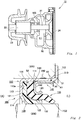
- Fig. 1 is a schematic cross-sectional view of a car water pump 10.
- the water pump 10 includes a rotating shaft 21 and a housing 30 with a shaft hole for the rotating shaft 21 to pass through.
- a bearing 22 is attached to the rotating shaft 21 for smooth rotation of the rotating shaft 21.
- a pulley 23 is attached to one end side of the rotating shaft 21, to which a rotary drive force is imparted via a belt or the like (not shown), while an impeller 24 is attached to another end side to pump cooling water (LLC) under pressure.
- LLC pump cooling water
- the sealing device 100 according to the present example is disposed in an annular gap between the rotating shaft 21 and the housing 30 in order to prevent this cooling water from leaking to the outside (i.e., the opposite side (A) to the sealed fluid side (L)).
- the sealed fluid is cooling water.
- the sealing device according to the present invention may be applied to other purposes.
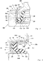
- the sealing device 100 according to Example 1 of the present invention will be described with reference to Fig. 2 and Fig. 3 .
- the sealing device 100 according to the present example serves the function of sealing an annular gap between a shaft hole provided in a housing 300 and a shaft 200 inserted through this shaft hole.
- the housing 300 corresponds to the above-mentioned housing 30, and the shaft 200 corresponds to the above-mentioned rotating shaft 21.
- the sealing device 100 is configured such that a resin sealing member 120 and an elastic sealing member 130, which is an elastic member (made of an elastic material such as rubber), are fixed to a cartridge case 110 so that they can be handled as one component.
- This sealing device 100 is made up of these three parts, a metal fixing member 140 for fixing the resin sealing member 120 and the elastic sealing member 130 to the cartridge case 110, and an outer peripheral sealing member 150 provided on the outer circumference of the cartridge case 110.
- the cartridge case 110 includes a cylindrical case main body 111, an outward flange 112 provided on the sealed fluid side (L) of the case main body 111, and a first supporting portion 113 provided on the opposite side (A) to the sealed fluid side (L) of the case main body 111, these being in one piece.
- the case main body 111 is fixed to the inner circumferential surface of the shaft hole formed in the housing 300 by being fitted therewith.
- the outer peripheral sealing member 150 which is an elastic coating, is provided on the outer circumference of this case main body 111.
- the outer peripheral sealing member 150 ensures prevention of water leakage through between the sealing device 100 and the shaft hole in the housing 300.
- part of the outer peripheral sealing member 150 is scraped off.
- the outward flange 112 is formed to extend radially outward from one end portion of the case main body 111 on the sealed fluid side (L).
- the cartridge case 110 is fitted to the shaft hole in the housing 300 until this outward flange 112 abuts on an end face of the housing 300, whereby the cartridge case 110 is set in position.
- the first supporting portion 113 is formed to extend radially inward from one end portion of the case main body 111 on the opposite side (A) to the sealed fluid side (L). A distal end portion of this first supporting portion 113 is formed to incline toward the direction of the sealed fluid (L) so as to form a back-up portion 114 that supports the resin sealing member 120.
- the first supporting portion 113 further includes a plurality of circumferentially spaced protrusions 113a. These protrusions 113a are formed so as to bite into the resin sealing member 120. Accordingly, the possibility of the resin sealing member 120 coming off of the cartridge case 110 is reduced.
- the resin sealing member 120 includes a body portion 121, and a sealing portion 122 extending from a radially inner side of the body portion 121 toward the direction of the sealed fluid (L), these being in one piece.
- the resin sealing member 120 is provided adjacent to the first supporting portion 113 on the sealed fluid side (L).
- the body portion 121 makes close contact with the first supporting portion 113, while the inner circumferential surface of the sealing portion 122 makes close contact with the outer circumferential surface of the shaft 200 so as to be slidable thereon.
- a portion between the body portion 121 and the sealing portion 122 that is bent in a curve is supported by the back-up portion 114.
- the resin sealing member 120 is a disc-like member with a hole in the center before being assembled to the cartridge case 110 (when not subjected to external forces). Having said that, the inner circumferential end portion of the resin sealing member 120, which will be the sealing portion 122, should preferably be bent in advance to some extent toward the direction of the sealed fluid (L) in order to facilitate insertion of the shaft 200.
- the elastic sealing member 130 includes an annular body portion 131, a cylindrical portion 132 extending from a radially inner side of the body portion 131 toward the direction of the sealed fluid (L), and a sealing lip portion 133 inclined radially inward from the end portion of the cylindrical portion 132, these being in one piece.
- the elastic sealing member 130 is provided adjacent to the resin sealing member 120 on the sealed fluid side (L).
- the body portion 131 makes close contact with the body portion 121 of the resin sealing member 120 on the sealed fluid side (L), while the inner circumferential surface of the cylindrical portion 132 at least partially makes close contact with the outer circumferential surface of the sealing portion 122 of the resin sealing member 120.
- the sealing lip portion 133 makes close contact with the outer circumferential surface of the shaft 200 so as to be slidable thereon at a point further closer to the sealed fluid (L) than the distal end of the sealing portion 122 of the resin sealing member 120.
- the body portion 131 is provided between the body portion 121 of the resin sealing member 120 and a second supporting portion 142 of the fixing member 140 to be described later, and formed such that its outer circumferential surface makes close contact with the inner circumferential surface of the case main body 111.
- the metal fixing member 140 is made up of a cylindrical portion 141, the second supporting portion 142 extending radially inward from an end portion on the opposite side (A) to the sealed fluid side (L) of the cylindrical portion 141, and a tapered portion 143 extending from the distal end of the second supporting portion 142 toward the direction of the sealed fluid (L) so as to increase in diameter.
- the cylindrical portion 141 is fixed to the inner circumferential surface of the case main body 111.
- the outer diameter of the cylindrical portion 141 is set to be equal to or smaller than the inner diameter of the case main body 111, and the cylindrical portion 141 and the case main body 111 are secured by welding.
- the cylindrical portion 141 may be welded at an end portion on the sealed fluid side (L) as indicated by arrow X1 in Fig. 2 , or at an interface between the inner circumferential surface of the case main body 111 and the outer circumferential surface of the cylindrical portion 141 as indicated by arrow X2 in Fig. 2 .
- the welding point should preferably be near the end portion of the cylindrical portion 141 on the sealed fluid side (L) so that the heat generated during the welding is conducted less to the elastic sealing member 130.
- the portion bent in a curve that connects the second supporting portion 142 and the tapered portion 143 provides a support for the outer circumferential surface of the cylindrical portion 132 of the elastic sealing member 130.
- the sealing lip portion 133 is prevented from separating from the outer circumferential surface of the shaft 200.
- the tip of the tapered portion 143 is separated from the outer circumferential surface of the cylindrical portion 132 of the elastic sealing member 130 so that it is unlikely to damage the cylindrical portion 132.
- the resin sealing member 120 and the elastic sealing member 130 are fixed by being held in between the first supporting portion 113 of the cartridge case 110 and the second supporting portion 142 of the fixing member 140.
- An annular space S2 is formed between an outer wall surface of the portion 144 connecting the cylindrical portion 141 and the second supporting portion 142 of the fixing member 140, and the elastic sealing member 130.
- a receiving jig 500 that provides a base, a pressing member 600, and a laser light source 650 are used.
- the receiving jig 500 includes a base portion 510 and a cylindrical portion 520.
- the cartridge case 110 to which the resin sealing member 120, elastic sealing member 130, and fixing member 140 have already been mounted, is assembled to this receiving jig 500. Since the outer diameter of the cylindrical portion 141 of the fixing member 140 is set to be equal to or smaller than the inner diameter of the case main body 111, the fixing member 140 can be mounted to the cartridge case 110 with hardly any pressure.
- the cylindrical portion 520 of the receiving jig 500 has an inner diameter slightly larger than the outer diameter of the case main body 111. Therefore, hardly any pressure is required when fitting the cartridge case 110 into the receiving jig 500.
- the second supporting portion 142 of the fixing member 140 is pressed toward the base portion 510 of the receiving jig 500 by the tip of a cylindrical pressing portion 610 provided on the pressing member 600.
- a laser beam L is emitted from the laser light source 650 to weld the cylindrical portion 141 and the case main body 111 securely together.
- the outer diameter of the cylindrical portion 141 of the fixing member 140 is set to be equal to or smaller than the inner diameter of the case main body 111, there is hardly any friction between the cylindrical portion 141 and the case main body 111.
- the pressure applied by the pressing member 600 on the second supporting portion 142 of the fixing member 140 is equal to the repulsive force from the elastic sealing member 130 applied on the second supporting portion 142.
- the fixing member 140 is fixed to the case main body 111 at a position where the repulsive force from the elastic sealing member 130 applied on the second supporting portion 142 is within a predetermined range.
- a load sensor may be provided to one of the receiving jig 500 and the pressing member 600, so that the movement of the pressing member 600 is stopped when the load detected by this load sensor falls within a predetermined range, to carry out the welding.
- the sealing device 100 With the laser light source 650 alone being fixed, the sealing device 100 may be rotated together with the receiving jig 500 and the pressing member 600 while the laser beam L is emitted, so that the sealing device can be welded all around. While the welding is performed with a laser beam L in the present example, various other known techniques (such as TIG welding) may be adopted for the welding. The welding may be performed all around as described above, or at several circumferentially spaced points.
- the outer diameter of the cylindrical portion 141 of the metal fixing member 140 is set to be equal to or smaller than the inner diameter of the case main body 111.
- a configuration is adopted in which the cylindrical portion 141 and the case main body 111 are secured by welding. Accordingly, in comparison to the case where the fixing member 140 is press-fitted, the positioning precision of the fixing member 140 can be improved. Therefore, a separate component dedicated for fixing the resin sealing member 120 in position as was conventionally practiced (such as the first supporting member 740 and second supporting member 750 made of metal in the conventional example described above) is not required. Accordingly, the number of components can be reduced.
- the fixing member 140 Since the fixing member 140 has the cylindrical portion 141, and this cylindrical portion 141 is secured to the case main body 111, the fixing member 140 is prevented from tilting in the axial direction relative to the case main body 111. Thus, the attitude of the fixing member 140 can be maintained stably. Assuming that the fixing member 140 has no cylindrical portion 141, the second supporting portion 142 could be fixedly welded to the case main body 111 at the outer peripheral edge thereof. In this case, however, there would be a concern that the second supporting portion 142 would tilt such that its radially inner side is oriented toward the direction of the sealed fluid (L), which would cause the attitudes of the resin sealing member 120 and elastic sealing member 130 unstable.
- L sealed fluid
- the attitude of the resin sealing member 120 can be made stable, so that the device can exhibit its sealing function in a stable manner. Also, there is no need to dispose part of an elastic component (such as the outer peripheral sealing portion 731 of the elastic sealing member 730 in the conventional example described above) on the outer side of the outer circumferential surface of the resin sealing member 120, so that the sealing device 100 can be reduced in the radial size.
- an elastic component such as the outer peripheral sealing portion 731 of the elastic sealing member 730 in the conventional example described above
- the annular space S2 is formed between an outer wall surface of the portion 144 connecting the cylindrical portion 141 and the second supporting portion 142 of the fixing member 140, and the elastic sealing member 130. Therefore, the heat generated during the welding is prevented from being conducted to the elastic sealing member 130.
- the elastic sealing member 130 can be positioned more precisely, so that the attitude of the elastic sealing member 130 is made stable. Also, the body portion 131 of the elastic sealing member 130 can make close contact with the inner circumferential surface of the case main body 111 more precisely. Accordingly, the sealing function on the outer circumferential side is fully achieved without the need to dispose part of an elastic component (such as the outer peripheral sealing portion 731 of the elastic sealing member 730 in the conventional example described above) on the outer side of the outer circumferential surface of the resin sealing member 120.
- an elastic component such as the outer peripheral sealing portion 731 of the elastic sealing member 730 in the conventional example described above
- the fixing member 140 is fixed to the case main body 111 in a position where the repulsive force from the elastic sealing member 130 applied on the second supporting portion 142 is within a predetermined range. Accordingly, the resin sealing member 120 and elastic sealing member 130 can be fixed in position precisely.
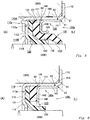
- Fig. 4 shows Example 2 of the present invention.
- a fixing member with a different structure from that of Example 1 will be illustrated.
- Other features in the configuration and effect are the same as those of Example 1, and therefore the same constituent elements are given the same reference numerals and the descriptions thereof are omitted.
- the fixing member 140 according to Example 1 described above is provided with the tapered portion 143 extending from the distal end of the second supporting portion 142 toward the direction of the sealed fluid (L) so as to increase in diameter.
- This tapered portion 143 is provided in order to prevent the sealing lip portion 133 from separating from the outer circumferential surface of the shaft 200, as mentioned above.
- the metal fixing member 140a according to the present example therefore, is formed only by a cylindrical portion 141 and a second supporting portion 142 extending radially inward from an end portion of the cylindrical portion 141 on an opposite side (A) to the sealed fluid side (L).
- the fixing member 140a according to the present example is not provided with the tapered portion 143 as in the fixing member 140 shown in Example 1.
- Fig. 5 shows Example 3 of the present invention. While a configuration of the cartridge case made from one component was illustrated in the previously described Example 1, a configuration of the cartridge case made from two components will be illustrated in the present example. Other features in the configuration and effect are the same as those of Example 1, and therefore the same constituent elements are given the same reference numerals and the descriptions thereof are omitted.
- the cartridge case 110a is formed by a first cartridge case 110A and a second cartridge case 110B fixedly attached to this first cartridge case 110A by press-fitting.
- the first cartridge case 110A includes a cylindrical case main body 111, and an outward flange 112 provided on the sealed fluid side (L) of the case main body 111, these being in one piece.
- the second cartridge case 110B includes a first supporting portion 113 provided on the opposite side (A) to the sealed fluid side (L) of the case main body 111.
- the distal end portion of this first supporting portion 113 is formed to incline toward the direction of the sealed fluid (L) so as to form a back-up portion 114 that supports the resin sealing member 120.
- the roles and functions of the case main body 111, outward flange 112, first supporting portion 113, and back-up portion 114 are as have been described in Example 1.
- Fig. 6 shows Example 4 of the present invention. While one configuration in which the elastic member is an elastic sealing member was illustrated in the previously described Example 1, a configuration in which the elastic member does not have the sealing function will be illustrated in the present example. Other features in the configuration and effect are the same as those of Example 1, and therefore the same constituent elements are given the same reference numerals and the descriptions thereof are omitted.
- the elastic member 160 according to the present example is formed only by a cylindrical portion. Namely, it is formed only by a portion corresponding to the body portion 131 of the elastic sealing member 130 shown in the previously described Examples. Since the elastic member 160 according to the present example does not include a sealing lip portion, it employs the fixing member 140a illustrated in Example 2.
- the back-up portion 114 may not necessarily be provided depending on the environment of use, such as when there is no need to support the resin sealing member 120.
Landscapes
- Engineering & Computer Science (AREA)
- General Engineering & Computer Science (AREA)
- Mechanical Engineering (AREA)
- Sealing Devices (AREA)
- Sealing With Elastic Sealing Lips (AREA)
- Gasket Seals (AREA)
Abstract
Description
- The present invention relates to a sealing device that seals an annular gap between a housing and a shaft.
- Sealing devices are used in car water pumps for preventing water leakage (see Patent Literature 1). A sealing device according to a conventional example will be described with reference to
Fig. 7. Fig. 7 is a schematic cross-sectional view of the sealing device according to the conventional example. The illustratedsealing device 700 serves the function of sealing an annular gap between a shaft hole provided in a housing (not shown) and a rotating shaft (not shown) inserted through this shaft hole. - In the
sealing device 700 according to this conventional example, aresin sealing member 720 and anelastic sealing member 730 made of rubber or the like are fixed to acartridge case 710 so that they can be handled as one component. Thecartridge case 710 includes a cylindrical casemain body 711 fitted to an inner circumferential surface of the shaft hole, anoutward flange 712 extending radially outward from one end portion of the casemain body 711 on a sealed fluid side, and aninward flange 713 extending radially inward from an end portion of the casemain body 711 opposite from the sealed fluid side. Theresin sealing member 720 is firmly secured by being held in between a pair of first and secondmetal supporting members elastic sealing member 730 includes an outerperipheral sealing portion 731 that seals an annular gap between the outer circumferential surface of the second supportingmember 750 and the inner circumferential surface of the casemain body 711, and asealing lip portion 732 slidable on the outer circumferential surface of the rotating shaft. - With the
resin sealing member 720 fixed by the first supportingmember 740 and second supportingmember 750, and theelastic sealing member 730 being mounted on the inner circumferential side of the casemain body 711, anadapter 760 is press-fitted. Accordingly, theresin sealing member 720 andelastic sealing member 730 are fixedly set in position in the axial direction. The distal end of theinward flange 713 is press-joined so that theresin sealing member 720 andelastic sealing member 730 are fixedly set in position in the radial direction (see press-joinedportion 714 in the drawing). - The
adapter 760 is press-fitted, as mentioned above. Generally, it is difficult to achieve precise positioning of press-fitted members because of the high sliding resistance during the press-fitting. In the case with thesealing device 700 according to the conventional example shown inFig. 7 , however, theresin sealing member 720 is firmly secured by the first supportingmember 740 and second supportingmember 750, and the outer circumferential side of the second supportingmember 750 is elastically pressed by the outerperipheral sealing portion 731 of theelastic sealing member 730. Theresin sealing member 720 is therefore maintained in a stable attitude. Accordingly, theresin sealing member 720 fully exhibits its function. The sealing function on the outer circumferential side is also fully exhibited, since the annular gap between the outer circumferential surface of the second supportingmember 750 and the inner circumferential surface of the casemain body 711 is sealed by the outerperipheral sealing portion 731 of theelastic sealing member 730. - As described, the illustrated
sealing device 700 fully exhibits its function as a sealing device even if the positioning precision of theadapter 760 is low. The shortcoming of thissealing device 700, however, is that the number of parts is large as it requires several components. Generally, with an increase in the number of parts, not only the cost increases, but also measurement errors tend to be large, so that stricter dimension control is necessary. Another shortcoming is that it is difficult to reduce the radial size because of the configuration in which the annular gap between the outer circumferential surface of the second supportingmember 750 and the inner circumferential surface of the casemain body 711 is sealed by the outerperipheral sealing portion 731 of theelastic sealing member 730. It may therefore be impractical to adopt the configuration of the above-describedsealing device 700 if the annular gap between the housing and the shaft is small. - Patent Literature 1: Japanese Patent No.
5037682 - An object of the present invention is to provide a sealing device that can stably exhibit the sealing function and enables a reduction in the number of components as well as in the radial size.
- The present invention adopts the following means to achieve the object noted above.
- Specifically, a sealing device of the present invention is a sealing device for sealing an annular gap between a shaft hole provided in a housing and a shaft inserted through the shaft hole,
the sealing device comprising: - a metal cartridge case including a cylindrical case main body fitted to an inner circumferential surface of the shaft hole, and a first supporting portion extending radially inward from an end portion of the case main body on an opposite side to a sealed fluid side;
- a resin sealing member provided adjacent to the first supporting portion on the sealed fluid side and having a sealing portion that is slidable on an outer circumferential surface of the shaft;
- an elastic member provided adjacent to the resin sealing member on the sealed fluid side; and
- a metal fixing member including a cylindrical portion fixed to an inner circumferential surface of the case main body, and a second supporting portion extending radially inward from an end portion of the cylindrical portion on the opposite side to the sealed fluid side,
- wherein an outer diameter of the cylindrical portion is set to be equal to or smaller than an inner diameter of the case main body, and the cylindrical portion and the case main body are being secured by welding, and
- the resin sealing member and the elastic member are fixed by being held in between the first supporting portion and the second supporting portion.
- In the present invention, an outer diameter of the cylindrical portion in the metal fixing member is set to be equal to or smaller than the inner diameter of the case main body, and a configuration is adopted in which the cylindrical portion and case main body are secured by welding. Accordingly, in comparison to the case where the fixing member is secured by press-fitting, the fixing member can be positioned more precisely. Therefore, a separate component dedicated for fixing the resin sealing member in position as was conventionally practiced (such as the first supporting
member 740 and second supportingmember 750 made of metal in the conventional example described above) is not required. Accordingly, the number of components can be reduced. Moreover, since the fixing member can be positioned more precisely, the attitude of the resin sealing member can be made stable. Thus the sealing function can be exhibited in a stable manner. Also, there is no need to dispose part of an elastic component (such as the outerperipheral sealing portion 731 of theelastic sealing member 730 in the conventional example described above) on the outer side of the outer circumferential surface of the resin sealing member, so that the sealing device can be reduced in the radial size. - Preferably, an annular space may be formed between an outer wall surface of a portion connecting the cylindrical portion and the second supporting portion of the fixing member, and the elastic member.
- Accordingly, the heat generated during the welding is prevented from being conducted to the elastic member.
- Preferably, the elastic member may include:
- an annular body portion provided between the resin sealing member and the second supporting portion and having an outer circumferential surface that is in close contact with the inner circumferential surface of the case main body; and
- a sealing lip portion provided integrally with the body portion and being slidable on the outer circumferential surface of the shaft.
- Accordingly, the elastic member can provide a sealing between the inner circumferential surface of the case main body and the outer circumferential surface of the shaft. Also, as described above, since the positioning precision of the fixing member can be improved, the elastic member can be positioned more precisely, so that the attitude of the elastic member is made stable. Also, the body portion of the elastic member can make close contact with the inner circumferential surface of the case main body more precisely. Accordingly, the sealing function on the outer circumferential side is fully achieved without the need to dispose part of an elastic component (such as the outer
peripheral sealing portion 731 of theelastic sealing member 730 in the conventional example described above) on the outer side of the outer circumferential surface of the resin sealing member. - Preferably, the fixing member may be fixed to the case main body at a position where a repulsive force from the elastic member applied on the second supporting portion is within a predetermined range.
- Accordingly, the resin sealing member and elastic member can be fixed in position precisely.
- Various configurations described above may be adopted in as many combinations as possible.
- As described above, according to the present invention, the sealing device can stably exhibit the sealing function and enables a reduction in the number of components as well as in the radial size.
-
-
Fig. 1 is a schematic cross-sectional view of a water pump. -
Fig. 2 is a schematic cross-sectional view of a sealing device according to Example 1 of the present invention. -
Fig. 3 is a diagram for explaining how the sealing device according to Example 1 of the present invention is assembled. -
Fig. 4 is a schematic cross-sectional view of a sealing device according to Example 2 of the present invention. -
Fig. 5 is a schematic cross-sectional view of a sealing device according to Example 3 of the present invention. -
Fig. 6 is a schematic cross-sectional view of a sealing device according to Example 4 of the present invention. -
Fig. 7 is a schematic cross-sectional view of a sealing device according to a conventional example. - Hereinafter, modes for implementing the present invention will be exemplarily described in detail based on examples thereof with reference to the drawings. However, the dimensions, materials, shapes, relative arrangements and so on of constituent parts described in the examples are not intended to limit the scope of the present invention to these alone in particular unless specifically described.
- Application examples of the
sealing device 100 according to an example of the present invention will be described with reference toFig. 1. Fig. 1 is a schematic cross-sectional view of acar water pump 10. Thewater pump 10 includes arotating shaft 21 and ahousing 30 with a shaft hole for therotating shaft 21 to pass through. Abearing 22 is attached to therotating shaft 21 for smooth rotation of therotating shaft 21. Apulley 23 is attached to one end side of therotating shaft 21, to which a rotary drive force is imparted via a belt or the like (not shown), while animpeller 24 is attached to another end side to pump cooling water (LLC) under pressure. Thesealing device 100 according to the present example is disposed in an annular gap between therotating shaft 21 and thehousing 30 in order to prevent this cooling water from leaking to the outside (i.e., the opposite side (A) to the sealed fluid side (L)). Namely, in the present example, the sealed fluid is cooling water. Note that the sealing device according to the present invention may be applied to other purposes. - The
sealing device 100 according to Example 1 of the present invention will be described with reference toFig. 2 andFig. 3 . Thesealing device 100 according to the present example serves the function of sealing an annular gap between a shaft hole provided in ahousing 300 and ashaft 200 inserted through this shaft hole. When thesealing device 100 is applied to thecar water pump 10 described above, thehousing 300 corresponds to the above-mentionedhousing 30, and theshaft 200 corresponds to the above-mentionedrotating shaft 21. - The
sealing device 100 according to the present example will be described with reference particularly toFig. 2 . Thesealing device 100 is configured such that aresin sealing member 120 and anelastic sealing member 130, which is an elastic member (made of an elastic material such as rubber), are fixed to acartridge case 110 so that they can be handled as one component. Thissealing device 100 is made up of these three parts, ametal fixing member 140 for fixing theresin sealing member 120 and theelastic sealing member 130 to thecartridge case 110, and an outer peripheral sealingmember 150 provided on the outer circumference of thecartridge case 110. - The
cartridge case 110 includes a cylindrical casemain body 111, anoutward flange 112 provided on the sealed fluid side (L) of the casemain body 111, and a first supportingportion 113 provided on the opposite side (A) to the sealed fluid side (L) of the casemain body 111, these being in one piece. - The case
main body 111 is fixed to the inner circumferential surface of the shaft hole formed in thehousing 300 by being fitted therewith. The outer peripheral sealingmember 150, which is an elastic coating, is provided on the outer circumference of this casemain body 111. The outer peripheral sealingmember 150 ensures prevention of water leakage through between the sealingdevice 100 and the shaft hole in thehousing 300. In the process of fixedly fitting the casemain body 111 to the shaft hole formed in thehousing 300, part of the outer peripheral sealingmember 150 is scraped off. However, there is an annular space S1 formed by achamfer 310 near the open edge of the shaft hole in thehousing 300. Therefore, shavings of the outer peripheral sealingmember 150 being scraped off are accumulated in this annular space S1. Accordingly, the possibility of shavings entering into the sealed fluid (L) is reduced. - The
outward flange 112 is formed to extend radially outward from one end portion of the casemain body 111 on the sealed fluid side (L). Thecartridge case 110 is fitted to the shaft hole in thehousing 300 until thisoutward flange 112 abuts on an end face of thehousing 300, whereby thecartridge case 110 is set in position. - The first supporting
portion 113 is formed to extend radially inward from one end portion of the casemain body 111 on the opposite side (A) to the sealed fluid side (L). A distal end portion of this first supportingportion 113 is formed to incline toward the direction of the sealed fluid (L) so as to form a back-upportion 114 that supports theresin sealing member 120. The first supportingportion 113 further includes a plurality of circumferentially spacedprotrusions 113a. Theseprotrusions 113a are formed so as to bite into theresin sealing member 120. Accordingly, the possibility of theresin sealing member 120 coming off of thecartridge case 110 is reduced. - The
resin sealing member 120 includes abody portion 121, and a sealingportion 122 extending from a radially inner side of thebody portion 121 toward the direction of the sealed fluid (L), these being in one piece. Theresin sealing member 120 is provided adjacent to the first supportingportion 113 on the sealed fluid side (L). Thebody portion 121 makes close contact with the first supportingportion 113, while the inner circumferential surface of the sealingportion 122 makes close contact with the outer circumferential surface of theshaft 200 so as to be slidable thereon. A portion between thebody portion 121 and the sealingportion 122 that is bent in a curve is supported by the back-upportion 114. Theresin sealing member 120 is a disc-like member with a hole in the center before being assembled to the cartridge case 110 (when not subjected to external forces). Having said that, the inner circumferential end portion of theresin sealing member 120, which will be the sealingportion 122, should preferably be bent in advance to some extent toward the direction of the sealed fluid (L) in order to facilitate insertion of theshaft 200. - The
elastic sealing member 130 includes anannular body portion 131, acylindrical portion 132 extending from a radially inner side of thebody portion 131 toward the direction of the sealed fluid (L), and a sealinglip portion 133 inclined radially inward from the end portion of thecylindrical portion 132, these being in one piece. Theelastic sealing member 130 is provided adjacent to theresin sealing member 120 on the sealed fluid side (L). Thebody portion 131 makes close contact with thebody portion 121 of theresin sealing member 120 on the sealed fluid side (L), while the inner circumferential surface of thecylindrical portion 132 at least partially makes close contact with the outer circumferential surface of the sealingportion 122 of theresin sealing member 120. The sealinglip portion 133 makes close contact with the outer circumferential surface of theshaft 200 so as to be slidable thereon at a point further closer to the sealed fluid (L) than the distal end of the sealingportion 122 of theresin sealing member 120. Thebody portion 131 is provided between thebody portion 121 of theresin sealing member 120 and a second supportingportion 142 of the fixingmember 140 to be described later, and formed such that its outer circumferential surface makes close contact with the inner circumferential surface of the casemain body 111. - The
metal fixing member 140 is made up of acylindrical portion 141, the second supportingportion 142 extending radially inward from an end portion on the opposite side (A) to the sealed fluid side (L) of thecylindrical portion 141, and atapered portion 143 extending from the distal end of the second supportingportion 142 toward the direction of the sealed fluid (L) so as to increase in diameter. Thecylindrical portion 141 is fixed to the inner circumferential surface of the casemain body 111. The outer diameter of thecylindrical portion 141 is set to be equal to or smaller than the inner diameter of the casemain body 111, and thecylindrical portion 141 and the casemain body 111 are secured by welding. Thecylindrical portion 141 may be welded at an end portion on the sealed fluid side (L) as indicated by arrow X1 inFig. 2 , or at an interface between the inner circumferential surface of the casemain body 111 and the outer circumferential surface of thecylindrical portion 141 as indicated by arrow X2 inFig. 2 . In the case with the latter, however, the welding point should preferably be near the end portion of thecylindrical portion 141 on the sealed fluid side (L) so that the heat generated during the welding is conducted less to theelastic sealing member 130. The portion bent in a curve that connects the second supportingportion 142 and the taperedportion 143 provides a support for the outer circumferential surface of thecylindrical portion 132 of theelastic sealing member 130. Accordingly, the sealinglip portion 133 is prevented from separating from the outer circumferential surface of theshaft 200. The tip of the taperedportion 143 is separated from the outer circumferential surface of thecylindrical portion 132 of theelastic sealing member 130 so that it is unlikely to damage thecylindrical portion 132. - The
resin sealing member 120 and theelastic sealing member 130 are fixed by being held in between the first supportingportion 113 of thecartridge case 110 and the second supportingportion 142 of the fixingmember 140. An annular space S2 is formed between an outer wall surface of theportion 144 connecting thecylindrical portion 141 and the second supportingportion 142 of the fixingmember 140, and theelastic sealing member 130. - An assembling procedure of the
sealing device 100 according to the present example will be described with reference particularly toFig. 3 . In the present example, when assembling thesealing device 100, a receivingjig 500 that provides a base, a pressingmember 600, and alaser light source 650 are used. The receivingjig 500 includes abase portion 510 and acylindrical portion 520. First, thecartridge case 110, to which theresin sealing member 120, elastic sealingmember 130, and fixingmember 140 have already been mounted, is assembled to this receivingjig 500. Since the outer diameter of thecylindrical portion 141 of the fixingmember 140 is set to be equal to or smaller than the inner diameter of the casemain body 111, the fixingmember 140 can be mounted to thecartridge case 110 with hardly any pressure. Thecylindrical portion 520 of the receivingjig 500 has an inner diameter slightly larger than the outer diameter of the casemain body 111. Therefore, hardly any pressure is required when fitting thecartridge case 110 into the receivingjig 500. - Next, the second supporting
portion 142 of the fixingmember 140 is pressed toward thebase portion 510 of the receivingjig 500 by the tip of a cylindricalpressing portion 610 provided on thepressing member 600. With thepressing member 600 kept in position where a pressure within a predetermined range is being loaded, a laser beam L is emitted from thelaser light source 650 to weld thecylindrical portion 141 and the casemain body 111 securely together. As mentioned above, since the outer diameter of thecylindrical portion 141 of the fixingmember 140 is set to be equal to or smaller than the inner diameter of the casemain body 111, there is hardly any friction between thecylindrical portion 141 and the casemain body 111. Accordingly, the pressure applied by the pressingmember 600 on the second supportingportion 142 of the fixingmember 140 is equal to the repulsive force from theelastic sealing member 130 applied on the second supportingportion 142. Thus, through the welding described above, the fixingmember 140 is fixed to the casemain body 111 at a position where the repulsive force from theelastic sealing member 130 applied on the second supportingportion 142 is within a predetermined range. - Preferably, a load sensor may be provided to one of the receiving
jig 500 and thepressing member 600, so that the movement of thepressing member 600 is stopped when the load detected by this load sensor falls within a predetermined range, to carry out the welding. With thelaser light source 650 alone being fixed, thesealing device 100 may be rotated together with the receivingjig 500 and thepressing member 600 while the laser beam L is emitted, so that the sealing device can be welded all around. While the welding is performed with a laser beam L in the present example, various other known techniques (such as TIG welding) may be adopted for the welding. The welding may be performed all around as described above, or at several circumferentially spaced points. - As described above, in the
sealing device 100 according to the present example, the outer diameter of thecylindrical portion 141 of themetal fixing member 140 is set to be equal to or smaller than the inner diameter of the casemain body 111. In addition, a configuration is adopted in which thecylindrical portion 141 and the casemain body 111 are secured by welding. Accordingly, in comparison to the case where the fixingmember 140 is press-fitted, the positioning precision of the fixingmember 140 can be improved. Therefore, a separate component dedicated for fixing theresin sealing member 120 in position as was conventionally practiced (such as the first supportingmember 740 and second supportingmember 750 made of metal in the conventional example described above) is not required. Accordingly, the number of components can be reduced. Since the fixingmember 140 has thecylindrical portion 141, and thiscylindrical portion 141 is secured to the casemain body 111, the fixingmember 140 is prevented from tilting in the axial direction relative to the casemain body 111. Thus, the attitude of the fixingmember 140 can be maintained stably. Assuming that the fixingmember 140 has nocylindrical portion 141, the second supportingportion 142 could be fixedly welded to the casemain body 111 at the outer peripheral edge thereof. In this case, however, there would be a concern that the second supportingportion 142 would tilt such that its radially inner side is oriented toward the direction of the sealed fluid (L), which would cause the attitudes of theresin sealing member 120 andelastic sealing member 130 unstable. - Since the positioning precision of the fixing
member 140 can be improved, the attitude of theresin sealing member 120 can be made stable, so that the device can exhibit its sealing function in a stable manner. Also, there is no need to dispose part of an elastic component (such as the outer peripheral sealingportion 731 of theelastic sealing member 730 in the conventional example described above) on the outer side of the outer circumferential surface of theresin sealing member 120, so that thesealing device 100 can be reduced in the radial size. - The annular space S2 is formed between an outer wall surface of the
portion 144 connecting thecylindrical portion 141 and the second supportingportion 142 of the fixingmember 140, and theelastic sealing member 130. Therefore, the heat generated during the welding is prevented from being conducted to theelastic sealing member 130. - Furthermore, since the positioning precision of the fixing
member 140 can be improved as described above, theelastic sealing member 130 can be positioned more precisely, so that the attitude of theelastic sealing member 130 is made stable. Also, thebody portion 131 of theelastic sealing member 130 can make close contact with the inner circumferential surface of the casemain body 111 more precisely. Accordingly, the sealing function on the outer circumferential side is fully achieved without the need to dispose part of an elastic component (such as the outer peripheral sealingportion 731 of theelastic sealing member 730 in the conventional example described above) on the outer side of the outer circumferential surface of theresin sealing member 120. - In addition, the fixing
member 140 is fixed to the casemain body 111 in a position where the repulsive force from theelastic sealing member 130 applied on the second supportingportion 142 is within a predetermined range. Accordingly, theresin sealing member 120 andelastic sealing member 130 can be fixed in position precisely. -
Fig. 4 shows Example 2 of the present invention. In the present example, a fixing member with a different structure from that of Example 1 will be illustrated. Other features in the configuration and effect are the same as those of Example 1, and therefore the same constituent elements are given the same reference numerals and the descriptions thereof are omitted. - The fixing
member 140 according to Example 1 described above is provided with the taperedportion 143 extending from the distal end of the second supportingportion 142 toward the direction of the sealed fluid (L) so as to increase in diameter. Thistapered portion 143 is provided in order to prevent the sealinglip portion 133 from separating from the outer circumferential surface of theshaft 200, as mentioned above. Depending on the environment of use, however, there may not be a possibility that the sealinglip portion 133 separates from the outer circumferential surface of theshaft 200. Themetal fixing member 140a according to the present example, therefore, is formed only by acylindrical portion 141 and a second supportingportion 142 extending radially inward from an end portion of thecylindrical portion 141 on an opposite side (A) to the sealed fluid side (L). Thus the fixingmember 140a according to the present example is not provided with the taperedportion 143 as in the fixingmember 140 shown in Example 1. - Other features in the configuration of the fixing
member 140a are the same as those of Example 1 described above, and therefore the descriptions thereof are omitted. It goes without saying that the same effects as those of thesealing device 100 according to Example 1 are achieved by thesealing device 100a according to the present example, too. -
Fig. 5 shows Example 3 of the present invention. While a configuration of the cartridge case made from one component was illustrated in the previously described Example 1, a configuration of the cartridge case made from two components will be illustrated in the present example. Other features in the configuration and effect are the same as those of Example 1, and therefore the same constituent elements are given the same reference numerals and the descriptions thereof are omitted. - The
cartridge case 110a according to the present example is formed by afirst cartridge case 110A and asecond cartridge case 110B fixedly attached to thisfirst cartridge case 110A by press-fitting. Thefirst cartridge case 110A includes a cylindrical casemain body 111, and anoutward flange 112 provided on the sealed fluid side (L) of the casemain body 111, these being in one piece. Thesecond cartridge case 110B includes a first supportingportion 113 provided on the opposite side (A) to the sealed fluid side (L) of the casemain body 111. Similarly to Example 1, the distal end portion of this first supportingportion 113 is formed to incline toward the direction of the sealed fluid (L) so as to form a back-upportion 114 that supports theresin sealing member 120. The roles and functions of the casemain body 111,outward flange 112, first supportingportion 113, and back-upportion 114 are as have been described in Example 1. - Configurations other than those of the
cartridge case 110a are the same as those of Example 1 described above, and therefore the descriptions thereof are omitted. It goes without saying that the same effects as those of thesealing device 100 according to Example 1 are achieved by thesealing device 100b according to the present example. The fixingmember 140a illustrated in the previously described Example 2 may be adopted in thesealing device 100b according to the present example, as well. -
Fig. 6 shows Example 4 of the present invention. While one configuration in which the elastic member is an elastic sealing member was illustrated in the previously described Example 1, a configuration in which the elastic member does not have the sealing function will be illustrated in the present example. Other features in the configuration and effect are the same as those of Example 1, and therefore the same constituent elements are given the same reference numerals and the descriptions thereof are omitted. - The
elastic member 160 according to the present example is formed only by a cylindrical portion. Namely, it is formed only by a portion corresponding to thebody portion 131 of theelastic sealing member 130 shown in the previously described Examples. Since theelastic member 160 according to the present example does not include a sealing lip portion, it employs the fixingmember 140a illustrated in Example 2. - Configurations other than those of the
elastic member 160 are the same as those of Example 1 described above, and therefore the descriptions thereof are omitted. It goes without saying that the same effects as those of thesealing device 100 according to Example 1 are achieved by thesealing device 100c according to the present example, as well, except for the effects relating to theelastic sealing member 130. - While a configuration was illustrated in various examples described above in which the first supporting
portion 113 of thecartridge case portion 114, the back-upportion 114 may not necessarily be provided depending on the environment of use, such as when there is no need to support theresin sealing member 120. -
- 10:
- Water pump
- 21:
- Rotating shaft
- 22:
- Bearing
- 23:
- Pulley
- 24:
- Impeller
- 30:
- Housing
- 100, 100a, 100b, 100c:
- Sealing device
- 110, 110a:
- Cartridge case
- 110A:
- First cartridge case
- 110B:
- Second cartridge case
- 111:
- Case main body
- 112:
- Outward flange
- 113:
- First supporting portion
- 113a:
- Protrusion
- 114:
- Back-up portion
- 120:
- Resin sealing member
- 121:
- Body portion
- 122:
- Sealing portion
- 130:
- Elastic sealing member
- 131:
- Body portion
- 132:
- Cylindrical portion
- 133:
- Sealing lip portion
- 140,
- 140a: Fixing member
- 141:
- Cylindrical portion
- 142:
- Supporting portion
- 143:
- Tapered portion
- 150:
- Outer peripheral sealing member
- 160:
- Elastic member
- 200:
- Shaft
- 300:
- Housing
- 500:
- Receiving jig
- 510:
- Base portion
- 520:
- Cylindrical portion
- 600:
- Pressing member
- 610:
- Pressing portion
- 650:
- Laser light source
- L:
- Laser beam
- S1, S2:
- Annular space
Claims (4)
- A sealing device for sealing an annular gap between a shaft hole provided in a housing and a shaft inserted through the shaft hole, the sealing device comprising:a metal cartridge case including a cylindrical case main body fitted to an inner circumferential surface of the shaft hole, and a first supporting portion extending radially inward from an end portion of the case main body on an opposite side to a sealed fluid side;a resin sealing member provided adjacent to the first supporting portion on the sealed fluid side and having a sealing portion that is slidable on an outer circumferential surface of the shaft;an elastic member provided adjacent to the resin sealing member on the sealed fluid side; anda metal fixing member including a cylindrical portion fixed to an inner circumferential surface of the case main body, and a second supporting portion extending radially inward from an end portion of the cylindrical portion on the opposite side to the sealed fluid side,wherein an outer diameter of the cylindrical portion is set to be equal to or smaller than an inner diameter of the case main body, and the cylindrical portion and the case main body are being secured by welding, andthe resin sealing member and the elastic member are fixed by being held in between the first supporting portion and the second supporting portion.
- The sealing device according to claim 1, wherein an annular space is formed between an outer wall surface of a portion connecting the cylindrical portion and the second supporting portion of the fixing member, and the elastic member.
- The sealing device according to claim 1 or 2, wherein the elastic member includes:an annular body portion provided between the resin sealing member and the second supporting portion and having an outer circumferential surface that is in close contact with the inner circumferential surface of the case main body; anda sealing lip portion provided integrally with the body portion and being slidable on the outer circumferential surface of the shaft.
- The sealing device according to claim 1, 2, or 3, wherein the fixing member is fixed to the case main body at a position where a repulsive force from the elastic member applied on the second supporting portion is within a predetermined range.
Applications Claiming Priority (2)
| Application Number | Priority Date | Filing Date | Title |
|---|---|---|---|
| JP2014146540 | 2014-07-17 | ||
| PCT/JP2015/068299 WO2016009803A1 (en) | 2014-07-17 | 2015-06-25 | Sealing device |
Publications (2)
| Publication Number | Publication Date |
|---|---|
| EP3171057A1 true EP3171057A1 (en) | 2017-05-24 |
| EP3171057A4 EP3171057A4 (en) | 2018-04-11 |
Family
ID=55078303
Family Applications (1)
| Application Number | Title | Priority Date | Filing Date |
|---|---|---|---|
| EP15821724.0A Withdrawn EP3171057A4 (en) | 2014-07-17 | 2015-06-25 | Sealing device |
Country Status (5)
| Country | Link |
|---|---|
| US (1) | US10260633B2 (en) |
| EP (1) | EP3171057A4 (en) |
| JP (1) | JP6496922B2 (en) |
| CN (1) | CN106662251B (en) |
| WO (1) | WO2016009803A1 (en) |
Families Citing this family (9)
| Publication number | Priority date | Publication date | Assignee | Title |
|---|---|---|---|---|
| US20120153573A1 (en) * | 2010-12-20 | 2012-06-21 | Alfred Robert Wade | Fluid Seal Assembly |
| WO2016108591A1 (en) * | 2014-12-29 | 2016-07-07 | 씰링크 주식회사 | Sealing device for drive shaft |
| JP7062072B2 (en) * | 2018-08-28 | 2022-05-02 | Nok株式会社 | Sealed structure in resin cover |
| WO2020250613A1 (en) * | 2019-06-11 | 2020-12-17 | Nok株式会社 | Sealing device |
| DE102019006053B4 (en) * | 2019-08-28 | 2026-05-21 | Vr Automotive Dichtungssysteme Gmbh | Radial shaft seal |
| JP7400622B2 (en) * | 2020-05-15 | 2023-12-19 | 株式会社デンソー | Valve device and method for manufacturing the valve device |
| JP7310778B2 (en) * | 2020-10-16 | 2023-07-19 | 株式会社デンソー | valve device |
| JP2023149987A (en) * | 2022-03-31 | 2023-10-16 | 株式会社バルカー | dust seal ring |
| DE102022206783B4 (en) * | 2022-07-04 | 2026-04-30 | Volkswagen Aktiengesellschaft | Insertion element for inserting and positioning a shaft element, system with the insertion element, a method for assembling the system, and a method for replacing a component in the system |
Family Cites Families (13)
| Publication number | Priority date | Publication date | Assignee | Title |
|---|---|---|---|---|
| GB449634A (en) | 1935-03-29 | 1936-07-01 | Super Oil Seal Mfg Co England | Improvements in packing devices for shaft bearings |
| FR2087867A5 (en) | 1970-03-26 | 1971-12-31 | Johns Manville | |
| JPS62183168U (en) | 1986-05-13 | 1987-11-20 | ||
| US5921555A (en) * | 1997-04-10 | 1999-07-13 | Freudenberg-Nok General Partnership | Uni-directional seal for use on a shaft |
| JP2001317635A (en) * | 2000-05-02 | 2001-11-16 | Toyota Industries Corp | Lip type seal |
| US20090206555A1 (en) | 2006-07-07 | 2009-08-20 | Eagle Industry Co., Ltd. | Shaft seal apparatus |
| JP4875597B2 (en) * | 2007-11-28 | 2012-02-15 | イーグル工業株式会社 | Lip type seal |
| US8256772B2 (en) | 2008-11-27 | 2012-09-04 | Eagle Industry Co., Ltd. | Lip type seal |
| JP2010138986A (en) * | 2008-12-11 | 2010-06-24 | Panasonic Corp | Shaft sealing device |
| US8851480B2 (en) * | 2009-09-09 | 2014-10-07 | Eagle Industry Co., Ltd. | Lip type seal |
| US20130228978A1 (en) | 2011-03-31 | 2013-09-05 | Eagle Industry Co., Ltd. | Sealing device and sealing structure |
| JP5212670B2 (en) * | 2011-07-08 | 2013-06-19 | Nok株式会社 | Sealing device for water pump |
| JP6208665B2 (en) * | 2012-08-23 | 2017-10-04 | イーグル工業株式会社 | Sealing device |
-
2015
- 2015-06-25 EP EP15821724.0A patent/EP3171057A4/en not_active Withdrawn
- 2015-06-25 JP JP2016534346A patent/JP6496922B2/en active Active
- 2015-06-25 US US15/325,867 patent/US10260633B2/en not_active Expired - Fee Related
- 2015-06-25 WO PCT/JP2015/068299 patent/WO2016009803A1/en not_active Ceased
- 2015-06-25 CN CN201580033693.7A patent/CN106662251B/en not_active Expired - Fee Related
Also Published As
| Publication number | Publication date |
|---|---|
| CN106662251B (en) | 2019-04-12 |
| CN106662251A (en) | 2017-05-10 |
| JPWO2016009803A1 (en) | 2017-06-15 |
| EP3171057A4 (en) | 2018-04-11 |
| JP6496922B2 (en) | 2019-04-10 |
| WO2016009803A1 (en) | 2016-01-21 |
| US20170175898A1 (en) | 2017-06-22 |
| US10260633B2 (en) | 2019-04-16 |
Similar Documents
| Publication | Publication Date | Title |
|---|---|---|
| US10260633B2 (en) | Sealing device | |
| JP6208665B2 (en) | Sealing device | |
| US9856984B2 (en) | Sealing device | |
| EP3070378B1 (en) | Divided mechanical seal | |
| EP3184864A1 (en) | Sealing structure | |
| EP3222891B1 (en) | Sealing structure | |
| EP3244100A1 (en) | Sealing device | |
| US10738891B2 (en) | Seal assembly for a rotating member | |
| US9194498B2 (en) | Sealing device | |
| US9644745B2 (en) | Mechanical seal | |
| EP3376078A1 (en) | Mechanical seal | |
| EP2693089A1 (en) | Sealing device and sealing structure | |
| US8328201B2 (en) | Pumping seal assembly with angled spring | |
| EP2865927A1 (en) | Sealing device | |
| JP7046928B2 (en) | mechanical seal | |
| CN106030134A (en) | Bearing rings of rolling bearings | |
| US9297457B2 (en) | Sealing device | |
| US9175774B2 (en) | Radial shaft seal, radial shaft seal assembly and method of installation | |
| EP4357645A1 (en) | Sealing device |
Legal Events
| Date | Code | Title | Description |
|---|---|---|---|
| STAA | Information on the status of an ep patent application or granted ep patent |
Free format text: STATUS: THE INTERNATIONAL PUBLICATION HAS BEEN MADE |
|
| PUAI | Public reference made under article 153(3) epc to a published international application that has entered the european phase |
Free format text: ORIGINAL CODE: 0009012 |
|
| STAA | Information on the status of an ep patent application or granted ep patent |
Free format text: STATUS: REQUEST FOR EXAMINATION WAS MADE |
|
| 17P | Request for examination filed |
Effective date: 20170104 |
|
| AK | Designated contracting states |
Kind code of ref document: A1 Designated state(s): AL AT BE BG CH CY CZ DE DK EE ES FI FR GB GR HR HU IE IS IT LI LT LU LV MC MK MT NL NO PL PT RO RS SE SI SK SM TR |
|
| AX | Request for extension of the european patent |
Extension state: BA ME |
|
| DAV | Request for validation of the european patent (deleted) | ||
| DAX | Request for extension of the european patent (deleted) | ||
| A4 | Supplementary search report drawn up and despatched |
Effective date: 20180308 |
|
| RIC1 | Information provided on ipc code assigned before grant |
Ipc: F16J 15/3228 20160101ALI20180303BHEP Ipc: F16J 15/3232 20160101AFI20180303BHEP Ipc: F16J 15/3268 20160101ALI20180303BHEP Ipc: F16J 15/322 20160101ALI20180303BHEP |
|
| STAA | Information on the status of an ep patent application or granted ep patent |
Free format text: STATUS: EXAMINATION IS IN PROGRESS |
|
| 17Q | First examination report despatched |
Effective date: 20200107 |
|
| STAA | Information on the status of an ep patent application or granted ep patent |
Free format text: STATUS: THE APPLICATION HAS BEEN WITHDRAWN |
|
| 18W | Application withdrawn |
Effective date: 20200206 |